kessler电主轴说明书
- 格式:pdf
- 大小:3.02 MB
- 文档页数:55
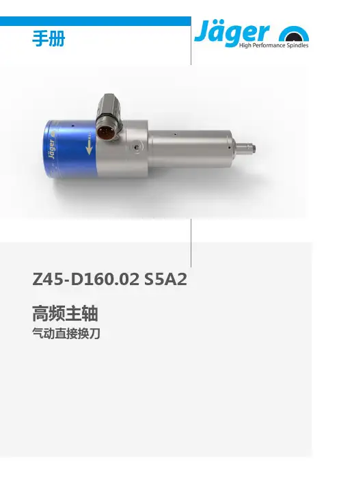
手册Z45-D160.02 S5A2高频主轴气动直接换刀电主轴的标记系列号额定转速因为本公司的电主轴始终保持最新技术研发水平,所以我们保留更改和与本说明书中的实施方案相比的技术改进和不同内容。
本手册文字说明经过极为认真地编写。
但是错误和疏漏在所难免,对于因此而引起的后果,Alfred Jäger GmbH概不承担法律责任及任何其它责任。
未经 Alfred Jäger GmbH 明确的书面同意,不得翻译和复制(即使是节选)。
目录:原厂手册的翻译文本1初步信息 5 1.1手册用途 (5)1.2符号说明 (5)2运输和包装 6 2.1电主轴的供货范围 (6)2.1.1维修工具 (6)2.1.2可选配件 (6)2.1.3随产品附带的技术资料 (7)2.2电主轴的包装 (7)3按规程使用 8 3.1允许的加工类型 (8)3.2允许材料 (8)4安全注意事项 9 4.1工作要具备安全意识 (10)4.2电主轴的停止运转 (11)4.3安装维修 (11)4.4改装维修 (11)4.5不正确的操作方法 (11)5技术说明 12 5.1电主轴的接口 (12)5.2电气连接 (12)5.3冷却 (13)5.3.1通过电主轴托架冷却 (13)5.4密封空气 (13)5.5气动刀具更换 (13)6技术参数 14 6.1尺寸 (15)6.2技术数据页 (KL2006 , 交流电机) (16)6.2.1功率图 (17)6.3电路图 (18)6.4电机保护 PTC 100° C (19)6.5转速传感器(数字磁敏电阻) (20)6.6ESD 保护 (20)6.7空气传播听觉范围内的声音 (21)7操作地点 228安装 23 8.1安装电主轴 (23)8.2介质引线直径 (23)8.3压缩空气 (24)8.3.1气体纯度等级 (ISO 8573-1) (24)8.3.2调节密封空气 (24)8.3.3调节值 (25)9调试 26 9.1进料示意图 (26)9.2每天启动 (27)9.3停止信息 (27)9.4存放之后启动 (27)10刀具更换 28 10.1顺时针旋转 (28)10.2气动直接换刀 (28)10.2.1更换夹头 (29)10.3刀具更换站(可选附件) (30)10.3.1气动直接换刀 (30)10.3.2安装更换站 (30)10.3.3维修 (30)11高速加工刀具 31 11.1折断的刀具 (31)12维修 32 12.1球轴承 (32)12.2每日清洁 (32)12.2.1开始工作前 (32)12.2.2每次刀具更换时 (32)12.2.3每次更换夹具时 (32)12.3存放时 (33)12.4月维修 (33)12.5在长期存放条件下 (33)12.6最长存放期限 (33)13拆除 34 13.1废物处理及环境保护 (34)14服务和维修 35 14.1特约维修站 (35)14.2工作故障 (36)15安装声明 39目录:初步信息1初步信息高速电主轴(电主轴)是适用于高速加工的高质量精密刀具。
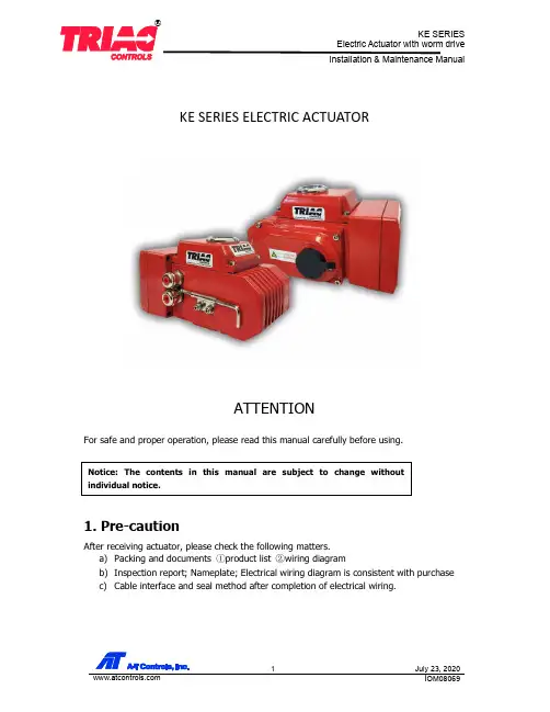
KE SERIES ELECTRIC ACTUATORATTENTIONFor safe and proper operation, please read this manual carefully before using.1. Pre-cautionAfter receiving actuator, please check the following matters.a) Packing and documents ①product list ②wiring diagramb) Inspection report; Nameplate; Electrical wiring diagram is consistent with purchase c) Cable interface and seal method after completion of electrical wiring.2. Part NameSight glass coverMotorSight glassbodyTerminal boardwormworm gearOutput shaftbearingGear box cover Transmission gear Motor endcap Rotor spindleIndicator dial3. Performance features3.1 HousingAluminum alloy housing. Anodized and polyester powder coated for strong corrosion resistance. Protection class IP67.3.2 MotorSmall size squirrel-cage motor with large torque and low inertia. Insulation class F and built-in overheat protection switch to prevent the motor from overheating.3.3 Manual operationSafe and reliable handle design for easy manual operation. Power must be "OFF" before manual operation. Clip on side of actuator housing to hold the handle when it is not being used.3.4 IndicatorIndicator installed on the central axis to show valve position. The convex lens design makes it easier to observe without water collecting on the surface of the indicator.3.5 HeaterHeater is used to control the temperature and avoid internal moisture condensation caused by temperature or weather changes. Keep electric elements dry.3.6 SealStandard product protection grade is IP67.3.7 Limit switchElectronic open/close position limit switch controlled by easy to adjust cam with accurate and convenient position setting. Set screw prevents unintended movement of cam.3.8 Self-lockingThe high precision worm and gear mechanism has high efficiency and can output large torque. Its self-locking function prevents reverse travel. Transmission part is stable and reliable, no need for additional grease.3.9 Cover boltCaptive cover bolts stay attached to cover when removed.3.10 InstallationMounting base is according to ISO5211 / DIN3337. Can be installed in both vertical and horizontal installation.3.11 CircuitControl circuit conforms to single or three-phase power supply standard. Circuit layout is simple and with compact terminals. Can effectively satisfy a variety of additional functional requirements.3.12 Mechanical StopMechanical open/close travel stop screw is easily adjustable, safe and reliably secured by locking nut/washer.4. SizingKE Series electric actuator output torque ranges from 440 in-lbs to 3500 in-lbs and can fit a variety of valves (ball valve, butterfly valve, etc.) and damper baffle, etc.1)Above table is for reference only.2)Sizing should be done after carefully reviewing the valve, temperature,characteristics of fluid, etc.3)For applications under abnormal conditions such as high and low temperature,seawater, severe corrosion and high vibration, please consult with factory beforeselecting actuator.4)Decisions by user ignoring our recommendation, we are not responsible for it.5. Mounting and adjusting1.Installation1)This product is not explosion-proof. Do not use it in an environment with flammable orcorrosive gas.2)Consult factory in advance if installing in area where actuator may be submerged.3)Allow space for wiring, maintenance and for manual operation of actuator.4)Use a protection cover to avoid rain and/or direct sunlight.5)Typical installation direction; indicator window to the top.2.Ambient temperature - Medium temperature1)When the environment temperature is below freezing, add desiccant heater inside theactuator.2)When fluid temperature is below freezing, the bracket connected with the valve shallspecial process.3. Assembly with valve Assembly procedure1) Be sure that power is off before making manual operation.2) Confirm that valve can turn smoothly by hand, then position it at full close. 3) Bolt bracket to valve if needed.4) Mount actuator to the bracket. Keep bolts loose.5) Position the actuator at 0° (close). Join the output shaft and the valve stem withcouplings.6) Tighten the bolts.7) Check with the attached crank handle if the valve will turn.Actuator mounting base is in accordance with ISO5211 standard. If the valve also conforms to the standard, direct mount may be possible. If valve does not conform to standard, an assembly bracket is needed.4. Adjustment1) Adjustment of Stroke limitTurn valve to the full closed position. Loosen set screw on cam and rotate cam to engage the limit switch. Tighten set screw to secure cam in place.KE-440/880KE-1700/35002) Adjustment of mechanical stopLoosen nuts on mechanical stops and back out stop limit set screws several turns. Moveactuator to the full-closed position. Tighten set screw on right until it stops. Reverse the set screw two full rotations then tighten the nut. Set the full-open position the same way.CLS ACLS OLS AOLSCLS ACLSOLS AOLSSTOPSTOP BOLT LOCK NUT3) Adjustment of potentiometerPotentiometer provides feedback signal in the actuators using three terminals. ② wiper arm of potentiometer. ① terminal which resistance between wiper arm decreases as actuator is open. ③ terminal which resistance between wiper arm decreases as actuator is closed. (Note: The resistance should not pass over 0Ω as this will cause position measurement error). Rotate valve to the full open position. Measure resistance between ② and ① . Rotate the potentiometer gear to adjust the resistance to between 35 Ω and 60 Ω.5. Test Operation A. Manual OperationRemove power off before making manual operation. Insert the manual handle into the hexagonal hole underneath the rubber cap.Note: Continuing to turn the actuator once the full open or full closed mechanical stop is reached will result in damage to other parts. Avoid using excessive force when turning with manual handle. B. Power OperationBefore making power operation:* Confirm that the indication on the position meter and the valve opening match each other. * Confirm that the circuits are properly wired, also that the unit operates in correct direction with external switches.1)Check the wiring diagram, power supply, input/output signal correctly. 2)Don’t change the internal wiring3)Please check the rotating direction if the power supply is three-phase3.1)Make sure the actuator is in the on/off position, turn on the power and input theopen signal3.2)If the actuator runs to the open direction, it means the wiring is correct. 3.3)If not, switch 2 of the phase wires.4)Actuator must not continuously operate for more than 15 minutesPOTENTIOMETERPOTENTIOMETER GEARSHAFT GEARLOCK NUT6. Maintenance & LubricationMajor parts are lubricated with long life Molybdenum base grease before shipment. Lubrication is in principle not required.When re-starting operation after a long period of rest, confirm the following. * Cut power off, confirm by manual operation that valve moves smoothly.* Open body cover and check that there is no condensation inside the unit, or that there are no problem with wiring.Note: After checking, secure the cover to prevent water ingress.7. Other1) The actuator or the brochure shows the reference wiring diagram.2) Please refer to the specification of Actuator module parts for modulating instructions.6. Trouble ShootingA-T Controls product, when properly selected, is designed to perform its intended function safely during its useful life. However, the purchaser or user of A-T Controls products should be aware that A-T Controls products might be used in numerous applications under a wide variety of industrial service conditions. Although A-T Controls can provide general guidelines, it cannot providespecific data and warnings for all possible applications. The purchaser / user must therefore assume the ultimate responsibility for the proper sizing and selection, installation, operation, and maintenance of A-T Controls products. The user should read and understand the installation operation maintenance (IOM) instructions included with the product, and train its employees and contractors in the safe use of A-T Controls products in connection with the specific application.While the information and specifications contained in this literature are believed to be accurate, they are supplied for informative purposes only. Because A-T Controls is continually improving and upgrading its product design, the specifications, dimensions and information contained in this literature are subject to change without notice. Should any question arise concerning these specifications, the purchaser/user should contact A-T Controls.For product specifications go to / A-T Controls, Inc. • 9955 International Boulevard, Cincinnati, OH 45246 • Phone: (513) 530-5175 • 。

YG62-60L使用说明书目录一、产品概述 (1)▷产品简介 (1)▷产品用途 (1)二、主轴外形图 (2)三、技术参数表 (3)四、电机特性曲线 (4)五、主轴安装说明 (5)▷测温传感器及其阻温特性对照表 (6)▷循环冷却系统说明 (8)▷换刀装置的控制 (8)▷空气密封及主轴吹尘的控制 (8)▷压缩空气气体质量要求 (9)▷跑合程序说明 (9)▷主轴驱动要求 (9)▷主轴安装要求 (10)六、使用注意事项 (11)▷主轴装机过程注意事项 (11)▷启动注意事项 (11)▷维护和保养注意事项 (12)一、产品概述▷产品简介1.本主轴为电机内装式主轴, 内置三相交流异步感应电机, 有变频器进行无级变速控制。
由于本主轴具有结构紧凑、重量轻、惯性小、振动小、噪声低等特点因此能够实现高转速, 高精度及高运转稳定性。
2.本主轴轴承采用油脂润滑陶瓷复合球轴承, 可在轴承的使用寿命周期内实现终生润滑3.本主轴使用强制冷却的方式对电机、前后轴承进行冷却。
冷却液流经主轴机体合理布置的循环水道带走主轴高速旋转产生的热量, 达到热平衡, 使电主轴的温度恒定在一定值内。
外置的冷却装置: 保持冷却液的温度恒定。
4.本主轴内置PTC130测温传感器( 其技术参数详见本说明书其它章节) , 如需进行对电机做温度保护时能够读取。
5.刀具加紧方式: 本主轴内置自动换刀装置, 刀柄形式为直接换刀, 标配为ф6, 可选配ф4, ф3.175.▷产品用途本产品为基础主轴, 主要用于雕铣机或加工中心进行有色金属、黑色金属、玻璃、石墨等材料的加工。
二、主轴外形图三、技术参数表20 电机绕组耐压试验1500V/min四、电机特性曲线▷功率、扭矩-转速曲线▷电压-频率曲线五、主轴安装说明▷测温传感器技术参数1.传感器类型: PTC(正温度系数), 常温阻值R25≤255Ω2.开关特性: 温控点Tk=130℃,Tk-5≤1650Ω,Tk+5≧4200Ω偏差△T=±5℃, Tk重复性△T=±0.5℃4.热动作时间: ≤2S5.最大工作电压30V(DC),绝缘强度2.5KW6.最高允许存放温度180℃, 最低允许存放温度-25℃▷循环冷却系统说明◆水冷要求: 推荐使用蒸馏水, 同时推荐使用费诺克斯( Femox) 保护剂F1(使用配比1:200).冷却液的温度建议为24℃-28℃, 当不能达到时, 应该与环境温度基本一致, 进水管、回水管温差不超过5℃◆一般在冷却系统的回水管中设置流量开关, 以便控制冷却液的流量, 确保主轴冷却液的正常供给。
电主轴使用说明电主轴是一种高速高刚度精密的电动机,其由精密滚动轴承支承,油脂润滑,外循环水冷却,雕刻(铣)主轴一般为立式使用,使用的方法正确与否将直接影响雕刻和雕铣质量,以及主轴的工作寿命。
1、避免撞击强烈撞击,特别是主轴端部及前端盖部位绝不许撞击,否则会损坏精密轴承及主轴精度,造成主轴回转精度的丧失。
2、正确安装和夹紧安装前应确认主轴电机状态正常,主要指外观无损伤,主轴转动轻匀。
用500V摇表查定子之对地绝缘电阻在100мΩ以上。
主轴电机套筒外径与夹持座孔间的配合公差必须保证主轴电机之套筒能顺利滑入座孔,在任何情况下都不能使用锤子或其他工具来使主轴定位,夹紧力不宜过大,否则会造成精密轴承的钢球滚道变形,使主轴精度及寿命受到影响。
夹持后要检查主轴前端锥孔定心面的跳动应不大于0.005MM,主轴回转轻匀。
3、筒夹(ER型)压帽和刀具的安装刀具的安装必须保证回转精度,否则会产生剧烈振动,影响雕刻(铣)质量和效率及轴承寿命。
必须十分小心的地擦净筒夹,压帽和刀具以及主轴前端之锥孔,装拆刀具应避免用力过猛。
组装后要查看刀具根部跳动﹤0.015MM若超差要通过反复放松和拧紧并调整变换刀具柄接触面来纠正,若无改善要检查各接触面是否处于正常状态,切忌乱敲打。
4、启动前必须1)确认主轴套筒所须的循环冷却水已开通,冷却水的温度一般不要超过35°c,但也不宜过低,不宜直接接用自来水,因水温过低会造成主轴电机内部热空气遇冷而形成凝水影响绝缘和轴承生锈,冷却水流量一般可在3-5L/MIN,冷却水应干净无杂屑以防堵塞通道。
冷却水箱中水量约50L—100L,建议水泵用AB-25或AB-50。
进出水口不能相距太近,必须使水在箱内有一冷却过程,力求使进出口水温差能达到2—3°c,要避免造成热水循环而达不到冷却效果。
2)确认电源电压,频率与主轴匹配关系正确,按主轴名牌数据或产品检测报告中提供的电压与频率对应关系设置变频器的U/F 曲线,主轴插头座的1号芯接地,2.3.4号芯接变频器的U V W。
电主轴使用说明范文1.介绍电主轴的作用和原理电主轴是一种用电能来驱动的主要加工工具,它可以实现高速、高精度和高效率的加工。
电主轴通过电机驱动,将电能转化成机械能,然后通过主轴本身的转动带动刀具进行加工。
电主轴通常由电机、轴承、主轴、冷却系统和刀具夹持系统等组成。
电主轴主要用于数控机床、工业机械制造等领域。
2.电主轴的安装和调试在安装电主轴之前,需要确保工作环境的清洁和干燥,防止灰尘和水分对其影响。
首先,将电主轴安装在机床上的主轴孔中,并使用螺栓和键进行固定。
然后,根据实际需要连接电源和电控系统。
在进行调试前,确保主轴和电机的运动部件是灵活的,没有阻塞或过紧。
调试时,根据电主轴的说明书进行相应的参数设置,如转速、转矩、加速度等。
调试完成后,检查电主轴是否能够正常运行,无异常振动和噪音。
3.电主轴的操作在使用电主轴之前,需要对其进行预热和冷却处理。
预热可以提高电主轴的工作效率和使用寿命,一般要求预热时间在5-10分钟。
冷却操作主要是为了降低电主轴的温度,避免过热造成损坏。
冷却方式可以根据具体工作要求选择,如空气冷却、水冷却和油冷却等。
在操作过程中,需要根据加工要求设置电主轴的运行参数,如转速、进给速度、铣削深度等。
同时,还需要根据具体工件材料选择合适的刀具和切削液,以达到最佳的加工效果。
4.电主轴的维护保养定期维护保养可以提高电主轴的使用寿命和稳定性。
首先,保持电主轴的工作环境清洁,防止灰尘和异物进入。
其次,定期检查电主轴的运动部件,如轴承是否磨损、润滑油是否充足等。
如果发现异常情况,需要及时进行维修或更换部件。
同时,根据使用频率和工作时间,定期更换润滑油和切削液,以保持电主轴的正常运行。
此外,还要注意避免过载和冲击,避免长时间高温运行,以避免电主轴受损。
5.电主轴的故障排除总结电主轴的使用需要注意安装和调试、操作规范、维护保养和故障排除等问题。
正确的操作和维护,可以保证电主轴的正常运行,并提高工作效率和加工质量。
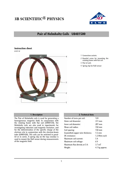
3B SCIENTIFIC ® PHYSICSPair of Helmholtz Coils U8481500Instruction sheet01/07 SP1 Connection sockets2 Knurled screw for mounting the rotating frame with flat coil3 Pair of coils4 Spring clip for Hall sensor1. DescriptionThe Pair of Helmholtz coils is used for generating a homogeneous magnetic field. In conjunction with the rotating frame with flat coil (U8481510), the Helmholtz coils are also used in experiments for investigating induction and magnetic levitation. and for the determination of the specific charge of the electron e/m in conjunction with the electron-beam tube (U8481420). The coils can be switched in paral-lel or in series. A spring clip on the top crossbar is used to mount the Hall sensor during measurements of the magnetic field.2. Technical dataNumber of turns per coil: 124 Outer coil diameter: 311 mm Inner coil diameter: 287 mm Mean coil radius: 150 mm Coil spacing: 150 mm Enamelled copper wire thickness: 1.5 mmDC resistance: 1.2 Ohm each Maximum coil current: 5 A Maximum coil voltage: 6 V Maximum flux density at 5 A: 3.7 mTWeight: 4.1 kg approx.3. Theoretical basesThe special arrangement of the coils is attributed to the physicist Hermann von Helmholtz. Two narrow coils with a large radius R are set up parallel to one another and on the same axis so that they are also separated by a distance R . The magnetic field of each individual coil is non-uniform. Upon superimposition of the two fields, a region with a magnetic field that is largely uniform is created between the two coils. Given the Helmholtz arrangement of the pair of coils and coil current I , the following holds true for the magnetic flux density B of the magnetic field:R n I B ⋅⋅µ⋅=02354where n = number of turns in each coil, R = mean coil radius and µ0 = magnetic field constant. For the Helmholtz pair of coils, we get: I .B ⋅⋅=−4104337 in Tesla (I in A).Fig. 1 Coils in Helmholtz arrangement4. Sample experimentsIn order to perform the experiments,the following equipment is also required:1 AC/DC power supply 0-20 V, 5 A U85211312 Escola 10 multimeter U8531160 1 Rotating frame with flat coil U84815104.1 Voltage induction in a magnetic field• Position the Helmholtz coils on the table top andconnect them in series to the DC power supply via an ammeter.• Screw the supports of the rotating frame with theflat coil to the crossbar of the Helmholtz coils, so that the flat coil can rotate in the middle of the uniform field produced by the Helmholtz coils. • Connect a voltmeter with a central zero pointdirectly across the coil.• Set the power supply current for the coils toabout 1.5 A.• Use the hand crank and observe the deflection ofthe voltmeter.• Change the speed of rotation so that a largerdeflection is obtained. The rotation speed needs to be low.In order to achieve a constant speed of rotation, use of a slowly rotating motor (e.g. 12 V DC motor U8552330) is recommended for driving the rotating frame.A precise voltage trace can also be observed and measured using an oscilloscope.4.2. Determinatio n o f the earth’s magnetic fieldfrom the induction voltageUsing the same experiment set-up, it is also possible to measure the earth’s magnetic field.• Align the Helmholtz coils in such a way that themagnetic field of the coils is parallel to the Earth’s field.• Rotate the flat coil and observe the voltage.• Increase current to the Helmholtz coils until thevoltage induced at the outputs of the flat coil is zero (so that the earth’s magnetic field and the field of the Helmholtz coils cancel out).• When the induced current is 0, then the mag-netic field in the coils is of the same magnitude as the Earth’s magnetic field.Elwe Didactic GmbH • Steinfelsstr. 6 • 08248 Klingenthal • Germany • VA0-12 V0-30 V++--Fig. 2 Experiment set-up with flat coil and driving motor。

OPERATION & MAINTENANCEINSTRUCTIONSLS 1010ELECTRIC HOISTMODEL NO: CH2500B, CH4000BPART NO: 7630386, 7630391INTRODUCTIONThank you for purchasing this CLARKE Electric Hoist.Before attempting to use this product, please read this manual thoroughly and follow the instructions carefully. In doing so you will ensure the safety of yourself and that of others around you, and you can look forward to your purchase giving you long and satisfactory service.GUARANTEEThis product is guaranteed against faulty manufacture for a period of 12 months from the date of purchase. Please keep your receipt which will be required as proof of purchase.This guarantee is invalid if the product is found to have been abused or tampered with in any way, or not used for the purpose for which it was intended.Faulty goods should be returned to their place of purchase, no product can be returned to us without prior permission.This guarantee does not effect your statutory rights.CONTENTSIntroduction (2)Guarantee (2)Contents (3)General safety rules (4)Electrical connections (5)Unpacking and assembly (6)Installation (6)Operation (7)Maintenance (8)Troubleshooting (9)Parts and servicing (9)Specifications (10)Exploded diagram & parts list (11)Declaration of conformity (13)Notes (14)GENERAL SAFETY RULESThere is a serious risk of personal injury if you do not follow all instructions laid down in this guide.1.This hoist is designed to be used by an able bodied, competent adult whohas read and understood these instructions.2.This hoist is designed for indoor, non-industrial use.3.Keep children, animals and bystanders away from the work area.4.Never use this hoist if you are ill, feeling tired, or under the influence ofalcohol or drugs.5.Before use, always inspect the machine and its mountings to ensure theyare in good condition. If any damaged or broken parts are found, the hoist should be removed from service and the parts renewed or repaired before further use.6.Before operating it isimportant to ensurethat the steel cableis correctly woundaround the drum7.Wear practical, protective clothing, gloves, footwear and a protectivehard hat. Avoid loose garments and jewellery that could catch in moving parts, tie back long hair8.Protect the machine from extreme weather conditions, i.e. frost and/orhigh temperatures.9.The machine is equipped with a thermal cut-out. If the load exceeds thecapacity of the machine this will cause the motor to overheat and the thermal cutout to activate, Let the hoist cool down before using it again.10.Make sure the load is balanced, stable and that personnel stand clear ofthe raised load.11.Contact your CLARKE dealer or the CLARKE Interational ServiceDepartment for any spare parts relating to this product.12.Ensure that the switches are kept in good condition.e this hoist for vertical lifts only. The hoist must only be fixed to a horizontalbeam/box section able to take the combined weight of the load and the hoist.ELECTRICAL CONNECTIONSConnect the mains lead to a standard, 230 Volt (50Hz) electrical supply through an approved 13 amp BS 1363 plug, or a suitably fused isolator switch.IMPORTANT: The wires in the mains lead are coloured in accordance with the following code:Green & Yellow -Earth Blue -Neutral Brown-LiveAs the colours of the flexible lead of this appliance may not correspond with the coloured markings identifying terminals in your plug proceed as follows:•Connect GREEN & YELLOW cord to terminal marked with a letter “E” or Earth symbol “” or coloured GREEN or GREEN & YELLOW.•Connect BROWN cord to terminal marked with a letter “L” or coloured RED.•Connect BLUE cord to terminal marked with a letter “N” or coloured BLACK.If this appliance is fitted with a plug which is moulded onto the electric cable (i.e. non-rewireable) please note:1.The plug must be thrown away if it is cut from the electric cable. There is a danger ofelectric shock if it is subsequently inserted into a socket outlet.2.Never use the plug without the fuse cover fitted.3.When replacing a detachable fuse carrier, ensure the correct replacement is used(as indicated by marking or colour code).4.Replacement fuse covers can be obtained from your local dealer or most electricalstockists.FUSE RATINGThe fuse in the plug must be replaced with one of the same rating (13 amps) and this replacement must be ASTA approved to BS1362.We strongly recommend that this machine is connected to the mains supply via a Residual Current Device (RCD)If in any doubt, consult a qualified electrician. DO NOT attempt any repairs yourself.WARNING: THIS APPLIANCE MUST BE EARTHEDUNPACKING AND ASSEMBLYUnpack your hoist and make sure that the following items are present. Should there be any damage caused during transit contact your Clarke dealer immediately.• 1 x Hoist Assembly• 1 x Hook / Pulley Assembly• 2 x Mounting Brackets• 1 x Fixings pack• 1 x Instruction manual (this book)INSTALLATIONThe hoist is provided with specially designed brackets allowing it to be attached to box sections or rectangular beams.Beam dimensions must be carefullycalculated and all mountings mustbe of adequate size and capable ofsustaining the maximum load of thehoist, plus the weight of the hoist andmountings.If there is any uncertainty. You shouldconsult a qualified engineer.OPERATIONEMERGENCY STOPRAISELOWERHOIST CONTROLUP/DOWN BUTTONS1.Press the Raise button to raise thehoist or the Lower button to lower the hoist as shown on the right.2.To stop motion release the button.EMERGENCY STOP BUTTONPress the emergency stop button to stop the hoist in an emergency.The emergency stop button can be reset by turning it clockwise until it ‘pops’ out.USING YOUR HOISTBefore use, check to ensure the emergency stop switch and the raise/lower buttons are in good condition.1.Play out the cable.•Keep the cable under tension so that the coils on the drum remain neatly in place. 2.Attach the hook to the load, the hook should be placed -•Directly above the centre of gravity of the load, and in line with the winch.•Ensure that nothing prevents a clean lift.CAUTION: MAKE SURE THE HOIST STOPS COMPLETELY BEFORE REVERSING DIRECTION.WARNING: ENSURE THAT LIFTING OPERATIONS ARE PLANNED, SUPERVISED AND CARRIED OUT IN A SAFE MANNER BY PEOPLE WHO ARE COMPETENT.•When lowering a load, the load will not stop immediately when the lower button is released, It may continue for a few more millimeters whilst the brake takes effect.HOIST CAPACITYWhen the hoist is used in its basicconfiguration as shown on the right,the rated lifting capacity is 125 Kg(200 Kg for the CH4000B)It is possible to double the capacityto 250 Kg (400 Kg for the CH4000B).To do this:1.Loop the cable around the pulleysupplied.2.Attach the hook to the hoistcasing as shown.MAINTENANCE•Fully unwind the cable and check its general condition, for fraying, corrosion etc.•Check the security and condition of the mountings and brackets.•Check the tightness of all bolts and screws.NOTE: When in constant use, the hoist should be inspected more frequently - at least monthly.TROUBLESHOOTINGPROBLEM CAUSE SOLUTIONWhen operating the switch the motor does not run.The cable or extension is notplugged in correctlyPlug in the power cable correctlyThe thermal cut out hasactivatedAllow the hoist to cool down Power failure Check plug fuseMotor hums but will not hoist The motor has overheated Allow it to cool downThe load exceeds the hoistcapacityReduce the loadBrake has become stuckduring storage.Press hoist button quickly a fewtimes to free brakeBrake does not operate, and load slips Brake is worn out Renew brake, Discontinue use andcontact your CLARKE dealer foradviceCable twisted frayed or kinked Incorrectly wound on drum.Replace cable. Cable stored unwound or inpoor conditions.Replace cable.If this does not solve your problem, please contact the Clarke service department. See belowPARTS AND SERVICINGFor Parts & Servicing, please contact your nearest dealer, or CLARKE International, on one of the following numbers.PARTS&SERVICETEL************PARTS&SERVICEFAX************or e-mail as follows:PARTS:*****************************SERVICE:*******************************SPECIFICATIONSCH2500CH4000 Load Capacity (Single Cable)125 kg200 kgLifting Speed (Single Cable)10 m/min10 m/minLifting Height (Single Cable)12 m12 mLoad Capacity (Double Cable)250 kg400 kgLifting Speed (Double Cable) 5 m/min 5 m/minLifting Height (Double Cable) 6 m 6 mCable Length12 m12 mCable Diameter 3 mm 3.8 mmDuty Cycle S3 20% - 10min S3 20% - 10min Electrical Supply230V @ 50Hz230V @ 50HzPower Rating540 W950 WPart Number76303867630391No Description1Hexagon Bolt2Spring Washer3Flat Washer4Fixing Ring5Support Frame6Support Panel7Locating Shaft8Gear Shaft9Flat Washer10Gear (A)11Gear (B)12X-Head Bolt13Switch14Paper Washer15Limit Switch Plate 16Flat Washer17Spring Washer18Nut19Cover20X-Head Bolt21Washer (1)22Washer (2)23Limit Pin24Driven Gear25Primary Gear26Pound Pin27Drum Shaft28Flat Key29Flat Key30Elastic Collar31Bearing32Screw 33Gear Case34Spring Washer35Flat Washer362nd Gear Wheel37Cushion Board38Front Cover39Bearing40Stator41Stator Shell42Rotor43Tripping Spring44Brake Disc45After Closure46Fan Blade47Fan Cover48Spring Washer49Flat Washer50Hexagon Bolt51Junction Box52Terminal53Cover54Holding Fixture55Holding Fixture56Safety Switch57Breaker Contactor58Locating Pin59Spring Tab60Cable61Socket62Holding Fixture63Handle Switch-Down64Condenser65Handle Switch -Up66Rise & Fall Switch673-Prong Plug68Hook Locknut69Hook Washer70Hexagon Bolt71Hexagon Bolt72Pulley73Splint74Pulley75Locknut761st Gearwheel77Flat Key78Gear Shaft79Bearing80Screw81Limiter82Hook83Rope Thimble84Wire Rope85Block86Aluminium Tube87Rope Drum88Wedge89BushingWhen ordering anyspare parts, pleasespecify eitherRKCH2500 or RKCH4000as required.No Description No DescriptionDECLARATION OF CONFORMITY。
在本产品使用说明书中,我们将尽力叙述各种与该产品使用相关的事项。
限于篇幅限制及产品具体使用等原因,不可能对产品中所有不必做和/或不能做的操作进行详细的叙述。
因此,本产品中没有特别指明的事项均视为“不可能”或“不允许”进行的操作。
本产品使用说明书的版权,归广州数控设备有限公司所有,任何单位与个人进行出版或复印均属于非法行为,广州数控设备有限公司将保留追究其法律责任的权利。
1DCY系列车床电主轴 使用说明书II前 言尊敬的客户:对您惠顾选用广州数控设备有限公司DCY系列车床电主轴(以下简称电主轴)产品,本公司深感荣幸与感谢!为了保证产品安全、正常与有效地运行,请您务必在安装、使用产品前仔细阅读本产品使用说明书。
安 全 警 告操作不当将引起意外事故,必须要具有相应资格的人员才能使用、操作本产品。
DCY 系列车床电主轴 使用说明书III安全警告及注意事项1 在正常气候条件下,用1000V 兆欧表(或绝缘电阻测试仪)测量内藏电机绕组对电主轴外壳的绝缘电阻,其值应不小于20 MΩ。
2 电主轴从零速至最高速空载运行应无异常噪声和振动时,方可接入负载运行。
3 只有具备相应资格的人员,才能加工、装配、维护电主轴。
4 在运输、贮存、装配时,务必注意保护电主轴不受外力冲击。
5 用户对产品的任何改动本公司将不承担任何责任,产品的保修单将因此作废。
所有规格和设计如有变化,本公司恕不另行通知。
连接及操作不当,将引起意外事故!请使用操作之前务必仔细阅读本使用说明书。
DCY系列车床电主轴 使用说明书IV安 全 责 任制造者的安全责任——制造者应对所提供的产品及随行供应的附件在设计和结构上已消除和/或控制的危险负责。
——制造者应对所提供的产品及随行供应的附件的安全负责。
——制造者应对提供给使用者的使用信息和建议负责。
使用者的安全责任——使用者应通过产品安全操作的学习和培训,并熟悉和掌握安全操作的内容。
——使用者应对自己增加、变换或修改原产品、附件后的安全及造成的危险负责。
主轴电机购买技巧买主轴电机的时候要看好以下几点:1、电主轴特性有恒转矩和恒功率两种,恒功率的贵些,雕刻机主轴采用恒转矩比较合适;2、种类有风冷和水冷,风冷主要是早期几百瓦的小功率主轴,现在雕刻机上基本上都是使用的水冷式电主轴,功率大噪音小;3、润滑方式有油雾和油脂,24000转以上的高转速电主轴采用油雾,由专门油路供油,安装使用复杂;雕刻机大多采用油脂润滑,转速可在6000-24000转左右变频调速;4、支撑方式有2轴承、3轴承和4轴承,3、4轴承适合雕刻钢材等重载荷1.5kW以上主轴采用较多,一般软金属采用2轴承轴承够用;5、主轴芯架有铝合金和不锈钢焊接形式,目前大多的主轴芯架采用的是铝合金,重量轻,但是体积大,现在有一些新产品采用不锈钢焊接芯架,同功率下可以缩小主轴尺寸,如通常1.5kW主轴的体积为Φ80×215mm左右,不锈钢焊接芯架主轴新产品可以做到Φ65×210mm左右,更适合雕刻机使用,不过价格贵一二百元钱;6、选择变频器功率要比主轴功率大些,这样能充分发挥主轴的输出功率,1.2kW主轴配1.5kW变频器,1.5kW主轴配2.2kW变频器。
主轴电机常见故障及排除方法主轴电机的维修注意事项1、主轴电机运行中发现声音或振动异常,应停机检查轴承,是否损坏,必要时更换新轴承,运行中发出异常气味,或停机切断电源,用兆母表插电机定子电阻,如电阻为0示为烧坏,应更换定子线圈。
2、主轴电机定期更换润滑脂,油脂为特种高速锂基润滑脂。
3、主轴电机轴承为精密工件,拆装时作用力不能直接作用轴承的滚珠上,外圈上,即在主轴上拆装轴承时,力应作用在轴承内圈上,以免降低轴承精度影响寿命。
4、清洗轴承时先93#标号浸15分钟后,用毛刷刷洗衣,每次应用清洁的清洗三次以上,严禁在未清洗干净时转动,待凉干后加入高速锂基润滑脂,油脂填充量约占轴承空间的20%-50%。
5、装配轴承时,角接触轴承应保证和拆卸时的配置一致(注意:轴承内圈或外圈端面的一边是宽边,别一边是窄边,切勿装错,否则会造成内外圈分离,主轴径向跳动磊,轴承易失损坏。

Technical DataOriginal InstructionsEasy and Compact Motor Starting SolutionsBulletins 140MP, 100-K, and 193-KOverviewBulletin 140MP Motor Protection Circuit Breakers (MPCBs) or Motor ProtectiveSwitching Devices (MPSDs) provide magnetic short circuit and thermal overloadprotection up to 32 A. They are tested in combination with Allen-Bradley® Bulletin100-K contactors to create two-component motor starters.Our easy and compact motor starting solutions are designed to ensure the smoothoperation of your motors, thereby enhancing the overall productivity of yoursystems. They offer a high degree of flexibility, allowing for precise adjustments tomatch the specific requirements of your motors. This precision, coupled with therobust protection features, helps prevent motor damage and extends the lifespan ofyour equipment.These devices are UL Listed as Manual Motor Controllers (with optional approvals forSuitable as Motor Disconnect and Suitable for use in Group Installation). Groupmotor installations eliminate the need for individual branch short circuit protectivedevices for each motor circuit, reducing panel space, installation and wiring time,and costs. There is only one Branch Circuit Protective Device (BCPD) for the “Group”.Features and Benefits Ratings•Protection and Control Functions:•UL group motor and IEC Type 1 and Type 2 ratings -Overload protection•CE, cULus, CCC, KC, EAC certifications-High short-circuit protection•Devices meet MPSD requirements per IEC 60947-4-1-Disconnect function•Devices meet circuit breaker standards per IEC 60947-2 -Phase loss protection•Rated up to 690V AC•Adjustable current setting for overload protection•Temperature compensation from -25…+55 °C (-13…+131 °F)•Suitable for three-phase and single- phase application•Suitable for use outside North America•Easy to install, snap-on mounting of accessories and modules•Provides disconnecting means for motor branch circuit •Modular Accessories•Offers short-circuit protection (magnetic protection)•Ideal for industrial or commercial application where space isat a premium•Provides overload protection (thermal protection)•Allows manual switching (motor control means)•Less panel depth requirements than standard IEC contactors•Budget-friendly motor starting solutiontwo-component starterbimetallic overload relayEasy and Compact Motor Starting Solutions Technical DataQuick Motor Starter SelectionThe two-component motor starter is a simple setup that includes a motor protection circuit breaker with a built-in thermal overload relay and a motor contactor. This combination provides protection and control for the motor. This is the most compact and most popular motor starting configuration.The three-component motor starter offers a more flexible solution. It consists of a motor circuit protector or fuses, a motor contactor, and a motor thermal overload relay. This configuration provides enhanced protection options in the separate thermal motor overload relay. When building a three-component motor starter, you can use either fuses or a motor circuit protector without thermal overload, such as the 140MT motor circuit protector.The following tables list a popular subset of these devices. More main device features, sizes, and accessory options are available. See publications 140-TD005, 100-TD013, and 193-TD010 at rok.auto/literature.Step 1: Choose Circuit Breaker and Optional Connection ModuleStep 2: Configure ContactorAfter you select your contactor in the preceding table, complete your contactor cat. no. by using the codes below for coil voltage and auxiliary contact configuration.Example: for a 24V DC contactor with integrated diode and 1 N.O. contact, Cat. No. 100-K09⊗✪ becomes Cat. No. 100-K09DJ10Step 3 (Optional): Select Motor Overload RelayRated Operating Current[A]Thermal Trip AdjustmentRange [A]MPCB(1) Cat. No.Optional ConnectingModule Cat. No.Contactor Cat.No.0.160.1…0.16140MP-A3E-A16140MP-A-PEK12100-K05⊗✪0.250.16…0.25140MP-A3E-A250.400.25…0.40140MP-A3E-A400.630.40…0.63140MP-A3E-A6310.63…1.0140MP-A3E-B101.6 1.0…1.6140MP-A3E-B162.5 1.6…2.5140MP-A3E-B254 2.5…4.0140MP-A3E-B406.3 4.0…6.3140MP-A3E-B63100-K09⊗✪10 6.3…10.0140MP-A3E-C10100-K12⊗✪128.0…12.0140MP-A3E-C121610.0…16.0140MP-A3E-C16(1)140MP devices have built in Trip Class 10 protection, and do not require a separate motor overload relay unless you change the motor protective device to fuses or a circuit breaker withoutthermal overload protection.140MP-A-PEK12100-K140MP⊗ Coil Voltage Code(1)(1)Additional coil voltages are available. See publication 100-TD013.✪Auxiliary ContactsCode Description Code DescriptionD120V AC, 60 Hz and 110V AC, 50 Hz10 1 N.O.B480V AC,60Hz011N.C.KJ24V AC, 50/60 HzKF230V AC, 50/60 HzDJ24V DC with integrated diodeThermal TripAdjustment Range[A]Overload RelayCat. No.For Use WithContactor0.1…0.16193-KA16100-K05…-K120.16…0.25193-KA250.25…0.40193-KA400.35…0.50193-KA500.55…0.80193-KA800.75…1.0193-KB100.90…1.3193-KB131.1…1.6193-KB161.4…2.0193-KB201.8…2.5193-KB252.3…3.2193-KB322.9…4.0193-KB403.5…4.8193-KB484.5…6.3193-KB635.5…7.5193-KB757.2…10.0193-KC109.0…12.5193-KC122Rockwell Automation Publication 140MP-TD002A-EN-P - August 2024Rockwell Automation Publication 140MP-TD002A-EN-P - August 20243Easy and Compact Motor Starting Solutions Technical DataAccessoriesApproximate DimensionsDimensions are shown in millimeters (inches). Dimensions are not intended for manufacturing purposes.100-K Miniature Contactor with 193-K Overload RelayCat. No. 140MP-A3E… ≤16 AAdditional ResourcesThese documents contain additional information concerning related products from Rockwell Automation. You can view or download publications at rok.auto/literature .Popular Accessories for 140MP MPCBsDescriptionCat. No.Front-mounted Auxiliary Contact •1 N.O.-1.N.C.•No additional space required 140MP-A-AFA11Front-mounted Auxiliary Contact•1N.O.•No additional space required140MP-A-AFA10Compact Bus Bars•UL: 600V, 60 A; IEC: 690V, 65 A •45 mm (1.77 in.) spacing •For use with front-mounted auxiliary contact •2 x 3 connections 140MP-A-W452Bus Bar Feeder Terminal (Flat)•Supply of compact bus bars •Increases terminal capacity 140MP-A-WTNEnclosure•Up to three padlocks in OFF position•Protection Class: IP65; UL/CSA Type 12•Red/yellow handle140MP-A-ENY65Popular Accessories for 100-K ContactorsDescriptionCat. No.Front-mounted Auxiliary Contacts •2 N.O.-2 N.C.•4-pole version•Mirror Contact performance per IEC 60947-4-1100-KFC22Front-mounted Auxiliary Contacts •1 N.O.-1 N.C.•2-pole version•Mirror Contact performance per IEC 60947-4-1100-KFC11Power Wiring Kit•For Reversing and Star/Delta combinations. Star-point bridge not included.•Min. interruption time 50 ms 100-KPRDC Diode Suppressor •12…250V DC •Plug-in type•Limits surge voltage on coil drop-off100-KFSD250Mechanical Interlock•For interlocking of two adjacent contactors•No added width to contactor assembly•Front mount plug-in type •Optional auxiliary contactblocks and suppressor modules mount onto the interlock100-KMCHResourceDescriptionIEC Contactor Specifications, publication 100-TD013Provides product selection and specifications for IEC contactors.Motor Protection Circuit Breaker and Motor Circuit Protector Specifications, publication 140-TD005Provides product selection and specifications for Bulletin 140MP/MT motor protection circuit breakers and motor circuit protectors.Bimetallic Overload Relay Specifications,publication 193-TD010Provides product selection and specifications for 193-K and 193-T1 bimetallic overload relays.Product Certifications website, rok.auto/certificationsProvides declarations of conformity,certificates, and other certification details.Publication 140MP-TD002A-EN-P - August 2024Copyright © 2024 Rockwell Automation, Inc. All rights reserved. Printed in the U.S.A.Rockwell Automation SupportUse these resources to access support information.Documentation FeedbackYour comments help us serve your documentation needs better. If you have any suggestions on how to improve our content, complete the form at rok.auto/docfeedback .Technical Support CenterFind help with how-to videos, FAQs, chat, user forums, Knowledgebase, and product notification updates.rok.auto/support Local Technical Support Phone Numbers Locate the telephone number for your country.rok.auto/phonesupport Technical Documentation CenterQuickly access and download technical specifications, installation instructions, and user manuals.rok.auto/techdocs Literature LibraryFind installation instructions, manuals, brochures, and technical data publications.rok.auto/literature Product Compatibility and Download Center (PCDC)Download firmware, associated files (such as AOP, EDS, and DTM), and access product release notes.rok.auto/pcdcRockwell Automation maintains current product environmental compliance information on its website at rok.auto/pec .Allen-Bradley, expanding human possibility, and Rockwell Automation are trademarks of Rockwell Automation, Inc.Trademarks not belonging to Rockwell Automation are property of their respective companies.Rockwell Otomasyon Ticaret A.Ş. Kar Plaza İş Merkezi E Blok Kat:6 34752, İçerenköy, İstanbul, Tel: +90 (216) 5698400 EEE Yönetmeliğine Uygundur。
凯利K S L 系列无刷无霍尔电机控制器用户手册适用的产品型号:K S L2L241004100K S L 24241150K S L 24200K S L 24300K S L 36100K S L 36150KSL36200KSL36300KSL48100KSL48150KSL48200KSL48300KSL48400BKSL48500B KSL72100KSL72150KSL72200KSL72300KSL72400BKSL72500B KSL96150KSL96250版本1.22013年4月目录第一章概述 (2)第二章主要特性和规格 (3)2.1基本功能 (3)2.2特性 (3)2.3规格 (4)2.4型号 (4)第三章安装和使用 (5)3.1安装控制器 (5)3.2连线 (6)3.3连接计算机串口 (10)3.4安装时检查 (10)3.5开始使用 (11)第四章维护 (16)4.1清洗 (16)4.2配置 (16)表1:LED错误代码 (17)联系我们: (19)1第一章概述本手册主要介绍凯利公司KSL系列控制器产品的特性,安装使用方法以及维护等方面的知识。
用户在使用凯利控制器之前,请详细阅读本手册,这会帮助您正确的安装和使用凯利控制器。
如果在使用过程中遇到任何问题,请从本文档最后一页查询联系方式与我们联系。
KSL无传感器无刷直流电机驱动控制器由凯利科技投资有限公司自主开发完成,特别适用于风机、水泵、空调压缩机、冰箱压缩机等直流无刷电机和驱动控制的应用场合。
凯利系列控制器采用大功率MOSFET高频设计,效率可达99%。
强大智能的微处理器为凯利系列控制器提供了全面精确的控制。
用户还可以通过我们提供的连接线连接计算机与控制器,自己配置控制器、引导测试并且可以简单快速的获得诊断信息。
2第二章主要特性和规格2.1基本功能(1)扩展的故障检测和保护。
可通过LED闪烁代码来识别故障。
(2)电池电压实时监控。
电主轴使用说明电主轴是一种高速高刚度精密的电动机,其由精密滚动轴承支承,油脂润滑,外循环水冷却,雕刻(铣)主轴一般为立式使用,使用的方法正确与否将直接影响雕刻和雕铣质量,以及主轴的工作寿命。
1、避免撞击强烈撞击,特别是主轴端部及前端盖部位绝不许撞击,否则会损坏精密轴承及主轴精度,造成主轴回转精度的丧失。
2、正确安装和夹紧安装前应确认主轴电机状态正常,主要指外观无损伤,主轴转动轻匀。
用500V摇表查定子之对地绝缘电阻在100мΩ以上。
主轴电机套筒外径与夹持座孔间的配合公差必须保证主轴电机之套筒能顺利滑入座孔,在任何情况下都不能使用锤子或其他工具来使主轴定位,夹紧力不宜过大,否则会造成精密轴承的钢球滚道变形,使主轴精度及寿命受到影响。
夹持后要检查主轴前端锥孔定心面的跳动应不大于0.005MM,主轴回转轻匀。
3、筒夹(ER型)压帽和刀具的安装刀具的安装必须保证回转精度,否则会产生剧烈振动,影响雕刻(铣)质量和效率及轴承寿命。
必须十分小心的地擦净筒夹,压帽和刀具以及主轴前端之锥孔,装拆刀具应避免用力过猛。
组装后要查看刀具根部跳动﹤0.015MM若超差要通过反复放松和拧紧并调整变换刀具柄接触面来纠正,若无改善要检查各接触面是否处于正常状态,切忌乱敲打。
4、启动前必须1)确认主轴套筒所须的循环冷却水已开通,冷却水的温度一般不要超过35°c,但也不宜过低,不宜直接接用自来水,因水温过低会造成主轴电机内部热空气遇冷而形成凝水影响绝缘和轴承生锈,冷却水流量一般可在3-5L/MIN,冷却水应干净无杂屑以防堵塞通道。
冷却水箱中水量约50L—100L,建议水泵用A B-25或AB-50。
进出水口不能相距太近,必须使水在箱内有一冷却过程,力求使进出口水温差能达到2—3°c,要避免造成热水循环而达不到冷却效果。
Capacity 1000 Lbs 1000 LbsTransmission JacksE-mail:***************Operating Instructions & Parts ManualModel Number KTI-63503KTI-63504(Air/ Manual)ONE YEAR LIMITED WARRANTYFor a period of one (1) year from date of purchase, KTI will repair or replace, at its option, without charge, any of its products which fails due to a defect in material or workmanship under normal usage. This limited warranty is a consumer's exclusive remedy.Performance of any obligation under this warranty may be obtained by returning the warranted product, freight prepaid, to K-Tool International 31111 Wixom Rd. Wixom, MI 48393, phone (248)669-5000.Except where such limitations and exclusions are specifically prohibited by applicable law, (1) THE CONSUMER'S SOLE AND EXCLUSIVE REMEDY SHALL BE THE REPAIR OR REPLACEMENT OF DEFECTIVE PRODUCTS AS DESCRIBED ABOVE. (2) KTI SHALL NOT BE LIABLE FOR ANY CONSEQUENTIAL OR INCIDENTAL DAMAGE OR LOSS WHATSOEVER. (3) ANY IMPLIED WARRANTIES, INCLUDING WITHOUT LIMITATION THE IMPLIED WARRANTIES OF MERCHANTABILITY AND FITNESS FOR A PARTICULAR PURPOSE, SHALL BE LIMITED TO ONE YEAR, OTHERWISE THE REPAIR, REPLACEMENT OR REFUND AS PROVIDED UNDER THIS EXPRESS LIMITED WARRANTY IS THE EXCLUSIVE REMEDY OF THE CONSUMER, AND IS PROVIDED IN LIEU OF ALL OTHER WARRANTIES, EXPRESS OR IMPLIED. (4) ANY MODIFICATION, ALTERATION, ABUSE, UNAUTHORIZED SERVICE OR ORNAMENTAL DESIGN VOIDS THIS WARRANTY AND IS NOT COVERED BY THIS WARRANTY.Some states do not allow limitations on how long an implied warranty lasts, so the above limitation may not apply to you. Some states do not allow the exclusion or limitation of incidental or consequential damages, so the above limitation or exclusion may not apply to you. This warranty gives you specific legal rights, and you may also have other rights which vary from state to state.K-Tool InternationalSave these instructions. For your safety, read, understand, and follow the information provided with and on this jack. The owner and operator of this equipment shall have an understanding of this jack and safe operating procedures before attempting to use. The owner and operator shall be aware that use and repair of this product may require special skills and knowledge. Instructions and safety information shall be conveyed in the operator's native language before use of this jack is authorized. If any doubt exists as to the safe and proper use of this jack, remove from service immediately. Inspect before each use. Do not use if broken, bent, cracked or damaged parts are noted. Any jack that appears damaged in any way, or operates abnormally shall be removed from service immediately. If the jack has been or suspected to have been subjected to a shock load (a load dropped suddenly, unexpectedly upon it), immediately discontinue use until jack has been checked by an KTI authorized service center. It is recommended that an annual inspection be done by qualified personnel. Labels and Owner's Manuals are available from manufacturer (see Replacement Parts section).PRODUCT DESCRIPTIONKTI Transmission Jacks are designed to be used as an aid in the removal and installation of vehicle component parts and assemblies, specifically transmissions. Model Nos. KTI-63503, KTI-63504 and KTI-63505 are for use under an overhead lift or in a garage pit. The air actuated function is an added feature of Model No. KTI-63504. Model No. KTI-63511 is for use under portable lift equipment, where vehicle must be supported by appropriately rated jack stands. With ModelKTI-63504,***************************************************************************** dependable, trouble free operation an air dryer and oiler is recommended.SPECIFICATIONSProduct appearance may differ slightly from this publication due to improvements in manufacturing, designand materials. However, performance characteristics will not be adversely affected.ASSEMBLY (KTI-63503, KTI-63504)Refer to figure 1:1. Three major parts should be included in package:(a) Hydraulic unit with pumping mechanism ( air motorequipped for model 63504),(b) saddle unit, and(c) 2 pieces of base half with hex socket bolts andwashers.2. Attach either one of the two base halves to the baseof the hydraulic unit, then secure using allen head bolts and washers provided. Then apply the same procedure to the other base frame. Use torque wrench to tighten to 30 lb.ft. Do not overtighten.3. Position the saddle unit above the ram piston, placethe saddle socket onto the ram piston. Secure using the set screw .Note: Before initial use, turn vent screw counterclockwise carefully, but no more than 1 full turn.ASSEMBLY (KTI-63505)Refer to figure 2:1. Three major parts should be included in package:(a) Hydraulic unit with pumping mechanism,(b) saddle unit, and(c) 2 pieces of base half with hex socket bolts andwashers.2. Attach either one of the two base halves to the baseof the hydraulic unit, then secure using allen head bolts and washers provided. Then apply the same procedure to the other base frame. Use torque wrench to tighten to 30 lb.ft. Do not overtighten.3. Attach the brackets to reservoir, then attach one endof the suppor bar to base half and the other end to the bracket. Secure with bolts and nuts provided. Repeat for all other three support bars.4. Slice the position handle to reservoir from top, thensecure with bolts and nuts provided.5. Position the saddle unit above the ram piston, placethe saddle socket onto the ram piston. Secure using the set screw.6. Remove oil filler screw. This will allow any pressurizedair to escape.7. Ensure oil level is just below the rim of the oil fillerscrew hole. Reinstall the oil filler screw.broken or cracked components are noted. Ensure that casters move freely. Check for and tighten any loose assemblies.2. Verify that the product and the application are compatible.3. With ram fully retracted, locate and remove the oil filler plug/screw. This will help release any pressurized air which may be trapped within the reservoir. Ensure the oil level is just below the oil filler plug/screw hole.Reinstall the oil filler plug/screw.For KTI-63511 only: Ensure the oil level is ~3/16"above the inner cylinder as seen from the oil filler plug hole.4. Before initial use, turn vent screw counterclockwise carefully, but no more than 1 full turn.5. KTI-63504 only: Pour a teaspoon of good quality, air tool lubricant into the air supply inlet of the lift control valve (See Fig 1). Connect to air supply and operate for 3 seconds to evenly distribute lubricant.Note: Air actuated product is fitted to accept the popular 1/4"npt air nipple. When installing air nipple, ensure that thread sealing compound enter the air supply inlet orifice.• Leer, comprender, y seguir las instrucciónes antes de utilizar el aparato.• El manual de instrucciónes y la información de seguridad deben estar comunicado en lengua del operador antes del uso.• No seguir estas indicaciónes puede causar daños personales o materiales.! ADVERTENCIAREPLACEMENT PARTSAvailable Parts: Please refer to the Parts drawings on page 8 thru 11 when ordering parts. Not all components of the jack are replacement items, but are illustrated as a convenient reference of location and position in the assembly sequence. When ordering parts, give Model No. and the description. To order parts contact KTI at (248)669-5000orE-mail:***************.MAINTENANCEImportant: Use only a good grade hydraulic jack oil. Avoid mixing different types of fluid and never use brake fluid,turbine oil, transmission fluid, motor oil or glycerin. Im-proper fluid can cause failure of the jack and the potential for sudden and immediate loss of load. Fill with good quality jack oil. We recommend Mobil DTE 13M or equivalent.Adding oilFor Models KTI-63503, KTI-63504 & KTI-63505:1. With saddle fully lowered, and jack in its upright, level position. Remove oil filler screw.2. Fill with oil until just below the rim of the oil filler screw hole. Reinstall the oil filler screw.For Model KTI-63511:1. With saddle fully lowered, remove oil filler plug.2. Fill to ~3/16" above the inner cylinder as seen from the Changing oilFor best performance and longest life, replace the complete fluid supply at least once per year.Note: Dispose of hydraulic fluid in accordance with local regulations.For Models KTI-63503, KTI-63504 & KTI-63505:1. With saddle fully lowered, remove the oil filler screw.2. Lay the jack on its side and drain the fluid into a suitable container.3. Fill with oil until just below the rim of the oil filler screw hole. Reinstall the oil filler screw.For Model KTI-63511:1. With saddle fully lowered, remove oil filler plug.2. Lay the jack on its side and drain the fluid into a suitable container.3. Fill to ~3/16" above the inner cylinder as seen from the oil filler plug hole. Reinstall oil filler plug.Lubrication1. A periodic coating of light lubricating oil to pivot points,axles and hinges will help to prevent rust and assure that wheels, casters and pump assemblies move freely.2. When used on a daily basis, air pump models should be internally lubricated before each use. Use only good quality air tool lubricant. If no inline oiler is used,pour a teaspoon of air tool oil into the inlet of the air control valve. Simply operate the jack using the air feature in order to fully distribute the oil.CleaningPeriodically check the ram for signs of rust or corrosion.Clean as needed and wipe with an oily cloth.Note: Never use sandpaper or abrasive material on these surfaces !StorageWhen not in use, store the jack with ram fully retracted and air supply disconnected.OPERATIONRaise saddleFor Models KTI-63503, KTI-63504 & KTI-63505:Caution! For Model KTI-63504, do not operate the jack by pumping the lift pedal and pressing the air pump pedal at the same time.a. Pump foot pedal or press air pump pedal until saddle reaches desired position.b. Follow vehicle manufacturers recommended procedures for removing the load as outlined in vehicle service manual or repair guide.c. Secure load with provided restraints. Ensure load's center of gravity is centered on the saddle and load is stable before moving jack.For Model KTI-63511:Locate and close release valve by turning knob clockwise firmly, then pump the pump handle until the load is contacted.Lower saddleCaution! Be sure all tools and personnel are clear before lowering load.For Models KTI-63503, KTI-63504 & KTI-63505:Slowly, gently apply downward pressure to the release valve pedal.For Model KTI-63511:Slowly, gently turn the release valve knob counterclockwise, NEVER MORE THAN 1/2 FULL TURN until the load is completely lowered.Note: Dynamic shock loads are created by quickly opening and closing the release valve as the load is being lowered,The resulting overload may cause hydraulic system failure.MAINTENANCE (continued)TROUBLESHOOTINGReplacement parts for Model KTI-63503Item Part#Description Qty1324-4-1900-208Screw Assembly22G36-6-1804-102Vent Screw Assembly13G36-3-1900-100Lift Pedal14G36-6-1809-102Release Valve Pedal15G36-3-5000-104Caster w/o Brake26G36-3-5001-106Caster w/ Brake27G36-3-2300-101Tilt Screw Assembly18G36-3-2301-103Tilt Screw Assembly19G36-3-0513-108Accessory Kit210G36-4-4200-10308Saddle Assembly (chain not included)1Item Part#Description Qty 1324-4-1900-208Screw Assembly2 2G36-6-1804-102Vent Screw Assembly1 3G36-3-1900-100Lift Pedal1 4G36-6-1809-102Release Valve/ Air Pump Pedal2 5G36-3-5000-104Caster w/o Brake2 6G36-3-5001-106Caster w/ Brake2 7G36-3-2300-101Tilt Screw Assembly1 8G36-3-2301-103Tilt Screw Assembly1Item Part#Description Qty 1324-4-1900-208Screw Assembly2 2G37-3-1320-109Bracket2 3G37-3-1806-105Handle1 4G36-3-1900-100Lift Pedal1 5G36-6-1809-102Release Valve Pedal1 6G37-6-1319-102Support Bar4 7G37-3-3300-103Base Half2 8651-1-0127-100Bolt4 9G37-4-5200-105Caster w/o Brake2 10G37-4-5201-107Caster w/ Brake2Replacement parts for Model 63511Item Part#Description Qty1505-9-0092-207Oil Filler Plug12G52-1-1000-100Hydraulic Unit13G36-6-7000-102Chain24G52-3-4204-103Saddle Assembly15G52-6-4207-107Angle Bar26G52-6-4402-105Tilt Screw17G52-6-4401-103Tilt Screw131111 Wixom Rd., Wixom, MI 48393 E-mail:***************(248) 669-5000。
使用说明书S系列主轴控制器V3.0版四川埃姆克伺服科技有限公司注意事项对本产品进行安装、接线、操作时,请遵守以下安全规定,否则可能造成设备损坏和人身伤害。
◆安装!受损和缺少零部件的控制器,请勿安装,否则会导致设备损坏和人员受伤。
◆接线◆运行◆维护与检查注意事项目录C o n t e n t s产品特点 1产品体系 2接线说明 3参数说明 8操作面板说明10监视参数介绍 11主轴功能详解 12试运转 17外形尺寸 18故障对策 20产品特点产品特点 1高性能控制功能全面精确:稳定的速度控制、精确的位置控制、优良的转矩控制。
安全&可靠产品符合国际标准,通过CE 认证。
设置多重保护电路,全面保护设备安全。
远程通讯功能(选配)产品具有远程通讯功能,只需连接一个SIM 卡模块,就可通过手机网络远程操作控制器。
强大的扩展能力(选配)控制器内可配置各种扩展模块,如数字端子扩展模块、模拟端子扩展模块、编码器反馈分频输出、485总线(ModBus RTU )、CANopen 、GSM/GPRS 模块、数码管显示模块、双位置环模块等接口,还可以根据用户的具体应用场合定制功能模块,方便与如PLC 、触摸屏、文本显示器等各种控制设备连接。
性能参数输 入 电 源输入电压 三相交流:380/400V输入频率 50Hz/60Hz 允许电压波动 +10%,-15%允许频率波动 ±5% 控 制 特 性控制方式 矢量控制速度控制范围0.01~500Hz , 如4极电机最高转速15000rpm速度控制精度 ±0.1% 加减速时间 0.05~3000Hz/s转矩控制特性 基频以下200%额定转矩输出;精度±5%位置控制精度 ±1脉冲制动方式 能耗制动,内置制动单元过载能力 两倍过载I/O 接 口数字量输入 10点,NPN 型、PNP 型可选 数字量输出4点,NPN 型、PNP 型 继电器输出 2个,DC30V/1A 或AC250V/1A模拟量输入 两路,A0:±10V ;A1 : 0~+10V 或4~20mA 可选 外部脉冲输入 一个,高速光耦,ABZ 相脉冲、方向+脉冲、CW 脉冲可选电机编码器输入 一个,RS422电平标准、旋变接口可选 电机编码器输出 一个,RS422电平标准,输出频率范围0~1MHz 扩展接口可内置或外置多种功能模块,如RS485(Modbus RTU)保护 功能 过电压保护、低电压保护、过电流保护、电机过热保护 功率模块过热保护、过载保护、输出短路保护、编码器异常保护工 作 环 境安装场所要求 避免阳光直射,无灰尘,无腐蚀、可燃性气体工作环境温度 -10℃~+45℃ 工作环境湿度 5~90%,不允许凝露工作海拔高度 0~3000米,1000米以上须降额使用 允许振动范围20Hz 以下:1G ;20~50Hz :0.2G适配电机功率(kW) 额定输出电流(A)额定输出容量(KVA)最小制动电阻接线说明4 IO 端子接线说明主回路端子说明端子名称 R ,S ,T B1,B2 B1/P , N U ,V ,W 用途三相交流电源输入连接制动电阻直流母线正负极连接电机接地注:1. 主回路接线电缆,应根据控制器功率选择合适截面的电缆线;2. 接地端子E 务必可靠接地,否则有触电的危险;3. 主回路的配线应该和控制回路的配线分开布线,否则会干扰控制信号;4. 禁止将交流电源输入接到输出端子U 、V 、W 上,否则会损坏控制器;5. B1/P 和N 端子只在15GKw 以上(含15GKw )控制器引出。
Assembly InstructionsGrinding spindleModel E13811BArticle number 000.633.533Serial number ______________Date of delivery ______________Original Assembly Instructions - GermanAll other languages are a translation of the original.Franz Kessler GmbHFranz-Kessler-Strasse 2 • 88 422 Bad BuchauTelephone: +49 (0)7582 / 809-0 • Fax: +49 (0)7582 / 809-170e-mail: franz-kessler@franz-kessler.de • web: http://www.franz-kessler.deOI 000.654.990_EN Created: 10/2010ContentsDeclaration of incorporation (5)1. About these assembly instructions (6)Scope of delivery (6)2. For your safety (7)General (7)Designated use (7)Non-authorised usage (7)Product identification (7)Important operating instructions (7)Operator's responsibility (8)Qualified technical staff (9)Work on the electrical system (9)Work on the hydraulic system (9)Personal protective equipment (9)Information about warning notices (10)Warning symbols (10)Warning levels (10)Damage to property (11)Other symbols used (11)Safety instructions (12)Danger due to electrical voltage (12)Danger due to hydraulic fluid (12)Danger due to compressed air (13)Danger of environmental pollution (13)3. Transport (14)4. Storage (15)5. Assembly (16)General informations (16)Installation position (16)Standard assembly information (16)Sequence for assembly (16)Electrical system: (17)Connection with plug (17)Possible plug connections (18)Frequency converter (20)Torque motor drive (21)Operating mode (21)Connection sensor system (22)Temperature sensor for motor coil (22)Motor shut-down temperature (22)Cooling connection (24)Motor cooling (24)Manufacturers of chemical additives for cooling water (26)Pneumatic connection (if applicable) (27)Compressed air (27)Bearings (if applicable) (28)Oil-air lubrication (if applicable) (28)Connection process oil-air lubrication system (30)Connection process spindle to oil separator (30)Lubricant recommendation (30)6. Commissioning (33)Carrying out commissioning (33)Start-up cycle (34)7. During operation (35)Ensuring cooling agent flow rate (if applicable) (35)Checks to be made during operation: (35)Tool and tool holder (if applicable) (35)Important operating instructions (36)Protecting bearings from external influences (36)Clamp with spring-return mechanism (36)Spindles with hollow clamping cylinders (37)Spindles with grease-lubricated bearings (37)8. Maintenance (38)Maintenance plan (39)Bearing maintenance (41)Service life greased bearings (41)9. Replacing parts (42)Replacing pulse transmitter (42)Replacing bearings (42)Replacing rotary union (42)Tool clamping system (42)Replacing clamping set (42)Wear and spare parts list (42)10. Decommissioning (44)Sequence for decommissioning (45)Disassembly (46)Disposal (46)11. Connections (47)12. Troubleshooting (48)13. Service and Support (49)KESSLER China (49)KESSLER USA (49)Declaration of incorporationfor partly completed machinery pursuant to the Machinery Directive 2006/42/EC, Annex II BWe the manufacturer:Franz Kessler GmbH, Franz-Kessler-Strasse 2, 88422 Bad Buchau (Germany),hereby declare that for the following product:Grinding spindleType: E13811BMaterial number 000.633.533• the following essential health and safety requirements in accordance with Annex I of the Machinery Directive have been applied and are complied with:1.1.2, 1.1.3, 1.1.5, 1.3.2, 1.3.4, 1.3.9, 1.5.1, 1.5.2, 1.5.3, 1.5.4, 1.5.5, 1.5.6, 1.5.8, 1.5.9,1.5.10, 1.5.11, 1.7.1, 1.7.2, 1.7.3, appendix VI.• The relevant technical documentation described in Annex VII B has been prepared.• In response to a reasoned request by national authorities the relevant technical documentation can be provided in writing.• The following person is authorised to compile the relevant technical documentation: Franz Kessler GmbH, Franz-Kessler-Strasse 2, 88422 Bad Buchau• The product further conforms to the requirements of the following EC directives:• Low Voltage Directive 2006/95/EC• Further, we declare that the following harmonized standards pursuant to the Low Voltage Directive have been applied.• EN 60034-1, Rating and performance• EN 60034-5, Degrees of protection• EN 60034-6, Methods of cooling• EN 60034-9, Noise limits• EN 60204-1, Safety of machinery• The partly completed machinery mentioned above may not be commissioned independently, but only after being installed in a predetermined machine or plant. Commissioning of the partly completed machinery is prohibited until the machine or plant in which the partly completed machinery is installed meets the requirements of the Machinery Directive 2006/42/EG.1. About these assembly instructionsThe copyright on these assembly instructions remains with Franz Kessler GmbH. They may not be copied, distributed or made accessible to others either in part or in full without permission.At the time of publication the information provided in these assembly instructions complied with technical standards. Subject to change without notice. We reserve the right to make alterations without notice.The original assembly instructions are provided in German. All other languages are a translation of the original.Contents of these assembly instructionsThese assembly instructions contain information on the conditions which must be met so that the partly completed machinery can be installed correctly without impairment to safety and health. Abbreviations used for connections refer to the dimension sheet in the appendix to these instructions. The abbreviations consist of letters and numbers, e.g. H21.The dimension sheet can be supplied as a PDF file and printed out larger at any time for better legibility. The PDF file can be requested from the Department for Technical Documentation. Technical specifications can be found in the technical data sheet or in the dimension sheet in the appendix to these assembly instructions.Scope of deliveryThe scope of delivery includes the following:• Spindle 000.633.533• Assembly instructions MA 000.654.989_DE (German)• Assembly instructions MA 000.654.990_EN (English)• Assembly instructions MA 000.660.807_RO (Romanian)• Technical data sheet• Dimension sheet• Parameter list2. For your safetyGeneralThe spindle is a high-speed, high-frequency electro spindle for grinding/milling. The high-frequency spindle is provided with a threaded tool mount.The spindle operates at a maximum speed of 120.000 rpm. The spindle is driven by a high-frequency three-phase AC motor.The spindle is designed in such a way that it can be operated safely and with a high degree of reliability after correct installation of electrical power, coolant, cooling lubricant, hydraulic system, pneumatic system and sensor system as well as correct programming of the motor control. The condition for this is that all technical parameters defined in these assembly instructions are observed at all times while taking the specified tolerances into account.The contents of these assembly instructions were compiled to the best of our knowledge und belief. However, it is possible that not all information which may be required for safe operation or which must be observed by the operator is available. If you have any questions, please contact our technical sales department.Designated useThe spindle is specially adapted for installation in machining centres. The spindle is exclusively designed to hold tools, to place them in a defined position and to them there during machining.Do not make changes to the spindle or its components. Dangers may arise from alterations or non-authorised use for which the existing protective equipment is not sufficient. This can lead to damage to property, serious injury or death.Non-authorised usageThe spindle is not authorised for:• operation in environments where there is danger of explosion,• operation under water,• operation outdoors.Any use other than the designated use is improper use and is not permitted.Product identificationThe identification data and technical characteristics are engraved on type plate of the spindle.Important operating instructions• In these assembly instructions the spindle will also be referred to as a unit.• Gross weight of the spindle: approx. 7 kg.• Maximum speed: 120,000 rpm.• A temperature monitoring device must always be connected.Operator's responsibilityRead these assembly instructions before assembly and commissioning, and follow the warning and safety instructions carefully. In addition to these instructions, the instructions attached to the unit must also be observed.Knowledge of these assembly instructions is essential for avoiding accidents and ensuring fault-free operation. Failure to observe the warning and safety instructions can result in injury or danger to life. Failure to observe important information is likely to lead to inferior production quality, frequent operational faults and damage to the unit, for which we as the manufacturer cannot accept liability.The operator must ensure:• that the unit is only assembled and used according to the designated use;• that all relevant laws, directives and rules for safety, prevention of accidents andenvironmental protection are observed;• that the necessary constructive safety and protection devices and appropriate warning notices are fitted;• that work is only carried out by sufficiently qualified and instructed technical staff;• that the assembly instructions and associated documentation are available to personnel whowork on the machine, and that they have been read and understood;• that the necessary personal protective equipment according to employment protection laws is provided and used;• that no constructional changes are made;• that stated maintenance intervals and tasks are observed.Qualified technical staffWork on the unit must be carried out strictly by qualified technical staff. The staff must have read and understood these assembly instructions.Qualified technical staff are staff who are familiar with the installation, assembly, commissioning and operation of the product and have the required qualifications such as:• qualified training, experience and appropriate instruction;• knowledge of observation of relevant standards, regulations, accident prevention regulations and operational conditions;• the ability to recognise and avoid possible dangers;• adequate safety and protective equipment;• first-aid training.Work on the electrical systemWork on the electrical system may only be carried out by qualified electricians or by trained technical staff under control and supervision of an electrician in accordance with electrotechnical rules.Work on the hydraulic systemWork on the hydraulic system may only be carried out by technical staff with additional skills and experience with hydraulic systems.Personal protective equipmentPersonal protective equipment in accordance with employment protection laws must be provided and used when working on the unit.Minimum requirements for protective equipment:• Protective clothing• Safety shoes• Protective gloves• Protective gogglesInformation about warning noticesTo emphasise safety relevant procedures in these assembly instructions the following warning notices apply. Warning notices consist of a signal word and a warning sign. If appropriate, prohibiting signs are used.Warning symbolsFollowing is a list of warning symbols used. They warn about the risk of injury. To avoid injury ordeath comply with all measures which are marked with a warning symbol.This warning symbol warns about the risk of injury.This warning symbol warns about the risk of injury from electric shock.This warning symbol warns about the risk of injury from hydraulic fluid and coolant.This warning symbol warns about the risk of injury from compressed air.This warning symbol warns about the risk of injury from suspended loads.This warning symbol warns about the risk of injury from crushing or becoming trapped.Warning levelsThe warning notices are graded by the seriousness of the danger. DANGER!Warns about dangers which will lead to irreversible injuries or death. Non-compliance with the warning notice will result in irreversible injuries or death!WARNING! Warns about dangers which can lead to serious injuries or death. Non-compliance with the warning notice can result in serious injuries ordeath.CAUTION!Warns about dangers which can lead to injuries. Non-compliance withthe warning notice can result in injuries.Damage to propertyNOTICE! Warns about possible damage to property. Non-compliance with thenotices can result in damage to property.Other symbols usedA prohibiting sign denotes a prohibited action, e.g. Entry for personswith pacemakers prohibited.Safety instructionsObserve the following safety instructions in order to avoid danger to persons or the environment.Danger due to electrical voltageAcute danger of injury or to life from electric shock! Electric shock can result in the following: cardiac arrest, respiratory arrest, neural damage, burns and consequential injury such as broken bones. Before working on the unit: (1) disconnect from mains,(2) ensure that power cannot be switched on again, (3) check that no electrical current is flowing, (4) earth and short-circuit,(5) shield, cover or otherwise isolate (adjacent) parts or components which are electrically live. In addition:connect the protective earth conductor; earth the housing;on assembly: first connect the earthing cable, then the power supply; on disassembly: first disconnect the power supply, then the earthing cable; ensure correct fit of plug connections;ensure that there is no strain on cables during transport, assembly and operation; work may only be carried out by a qualified electrician;when working on the electrical system ensure that a second technical person is present who can switch of the power supply in an emergency;only run the unit when the terminal box, switch cabinet etc. are shut.Danger due to hydraulic fluidDanger to health and the environment due to hydraulic fluid. Hydraulic fluid can become up to 80 °C hot and be under high pressure.Contact with hydraulic fluid can cause allergic reactions, skin and eye irritation, injuries and scalding.Hydraulic fluid can cause environmental damage.Before working on the hydraulic system, ensure that the power supply is switched off, and that the unit is free of electrical current.Before working on the hydraulic system, ensure that the system is free of pressure. To reduce pressure safely, slowly turn out the vent screw (approx. 1/2 revolution). Avoid lengthy skin contact with hydraulic fluid. Wear protective clothing, protective gloves and protective goggles.Use suitable collection devices for leaking hydraulic fluid. Dispose of hydraulic fluid in an environmentally compatible manner.Danger due to compressed airDanger of injury due to escaping compressed air or whirling tubing. Escaping compressed air can cause skin and eye injuries.An escaping air jet can cause swarf and other particles to be whirled through the air which can result in eye injuries.Loose pressurised tubing can whirl about and result in injuries.Before working on the pneumatic system ensure that the power supply is switched off, and that the pneumatic system is free of pressure. Use personal protective equipment.Danger to health and the environment due to cooling agents. Contact with cooling agents can cause allergic reactions, skin, eye and respiratoryirritation.Cooling agents can cause environmental damage.Before working on the cooling system ensure that the power supply is switched off, and that the cooling system is free of pressure.Avoid lengthy skin contact with cooling agents. Wear protective clothing, protective gloves and protective goggles.Use suitable collection devices for leaking cooling agents. Dispose of cooling agents in an environmentally compatible manner.Danger of environmental pollutionDanger to the environment from operating fluids! Operating fluids such as lubricating grease, hydraulic fluid, cooling agent, cleaning fluid etc. must not be allowed to enter the ground, the water supply or the sewer system. The smallest amount of these fluids can cause damage to health or the environment. Use suitable containers for collection, storage, transport and disposal so that no danger for persons or the environment can arise.3. TransportTransport may only be carried out by qualified technical staff or a specialised company.4. StorageNOTICE! NOTICE! Risk of damage from incorrect storage!• Incorrect storage can result in corrosion of the unit or damage to the bearings.Observe the following instructions for storage time, environmental conditions and protection against bearing damage.Storage timeThe maximum storage time is 18 months.Make a note of the date put into storage and the unit's identification.Additional rust protection measures are required for storage times over 7 days.Environmental conditionsThe temperature of the unit may not exceed 45 °C during storage.The storage area must have as constant a temperature as possible, between 4 °C and 45 °C. The storage area must be dry and free of dust and dirt. Storage outdoors is not permitted.To prevent condensation, the temperature must not fall below the dewpoint.Protection against bearing damageExposure of the unit to shock or vibrations can result in bearing damage in the form of standstill marks.• Vibrations of max. 0.1 mm/s are permitted for a storage time of up to 6 months.• Vibrations of max. 0.08 mm/s are permitted for a storage time of up to a maximum of 18 months.• If necessary store the unit on a base which isolates against vibration.Long storage times can result in standstill corrosion in the bearings.• The unit must be spun by technical staff every 1-2 months.5. AssemblyThe assembly section contains important information on the connections and the specifications for the required media.Work on the unit must be carried out strictly by qualified technical staff.Electrical system:Work on the electrical system may only be carried out strictly by an electrician.Ensure that a second qualified person is available to disconnect the power supply in the event of an emergency.Possible plug connectionsThis is a selection of possible connections. Please see the drawing, the dimension sheet and/or data sheet for further information.See the dimension sheet in the appendix to these instructions for other plug connections.Type A socketES converter J53terminal connection boardES Regler main terminal connection boardJ - Earth K - U L - V M - W A 12 ( ) - B 24 ( ) - C 11 ( ) - D 23 ( ) - E 25 ( ) - N 14 - U 15 - V 10 ( ) - W 2 - X14-In = electro spindle nominal current (A)( ) If the pins 19 and 20 on the J53 terminal connection board are connected to one another – see ES handbook.Type B socketES converter J53terminal connection boardES converter main terminal connection boardA - EarthB - U R - V ‘Q - WC 2 - F 14 - E 12 ( ) - G 25 ( ) - H 14 - K 15 - L 23 ( ) - M 24 ( ) - N - - P11 ( )-In = electro spindle nominal current (A)( ) If the pins 19 and 20 on the J53 terminal connection board are connected to one another – see ES handbook.Type "Schalt-bau" connec-tionES converter J53 terminalconnection boardES converter main terminal connection board1 - Earth2 - U3 - V4 - W 512 ( ) - 624 ( ) - 7 11 ( ) - 8 23 ( ) - 9 - - 10 25 ( ) - 11 14 - 12 15 - 13 2 - 14 10 ( ) - 1514-In = electro spindle nominal current (A)( ) If the pins 19 and 20 on the J53 terminal connection board are connected to one another – see ES handbook.Type Klingel socketES converter J53terminal connection boardES converter main terminal connection boardearth connection -Earth 1 (output) - U 2 (output) - V 3 (output) - W 4-5-6 (output)- - 1-2-3-4-5-6 (signal)--7 (signal) 10 ( ) -8 (signal) 14 -9 (signal) 14 -10 (signal) 15 -11 (signal) 12 ( ) - 12 (signal) 24 ( ) - 13 (signal) 11 ( ) - 14 (signal) 23 ( ) - 15 (signal) 23 ( ) - 16 (signal)2 ( ) -In = electro spindle nominal current (A) ( ) If the pins 19 and 20 on the J53 terminal connection board are connected to one another – see ES handbook.Frequency converterA frequency converter is not supplied with the spindle.Select a converter which is compatible with the maximum current, voltage and frequency as indicated on the type plate attached to the spindle.Torque motor driveNOTICE! Damage to the torque motor due to excessive voltage loads ispossible.Avoid damage to the torquemotor. Observe the followinginstructions:Electrical system oscillations may occur in the case of drive configurations with controlled feeds, for which direct drives such as torque motors are used. System oscillations can lead to excessive voltage load. Voltage loads must not exceed 2000V peak to peak with a build-up time of 10 kV/µs.Cable length, number of axes and motor size are influencing factors.When operating with a frequency changer with controlled feed, use an HFD* reactor with damping resistor to reduce system oscillations.For example: For example: A Siemens HFD-package consisting of an HFD reactor, a resistor anda wideband line filter.*HFD: High-frequency damping.Operating modeThe motor for the spindle drive is optimised according to DIN EN 60034-1.Torque at S1 (continuous operation)This is a permissible torque which must not be effectively exceeded for load cycles.Torque at S6 (continuous operation with intermittent load)Operation made up of a series of identical loads, each of which consists of operation time with constant load and idle time (without stopping the motor).Current changes have not been taken into account for a temperature change. This type of operation is defined by the duration of the load operation (or the percentage of intermittence) and the total duration of a cycle. The information given in this manual and, in particular, in this section, refers to a percentage of intermittence of 60% and a total duration of the work cycle of 10 minutes.For further information see the drawing and/or data sheet.Torque max.The maximum torque may not be applied for more than 1 second.Torque at standstillAt standstill, different loads occur in the individual phases. These may differ by a factor of up to √2. For this reason, the standstill torque must not exceed max. 0.7x torque at S1.Connection sensor systemThe unit has sensors which influence the control. Only correct connection of these sensors ensures fault-free operation.Work on the electrical system may only be carried out strictly by an electrician.Ensure that a second qualified person is available to disconnect the power supply in the event of an emergency.Hydraulic connectionWork on the hydraulic system must be carried out strictly by qualified technical staff with special knowledge and experience with hydraulic systems.Cooling connectionWork on the cooling system must be carried out strictly by qualified technical staff with special knowledge and experience with hydraulic systems.• Solids filter < 100 µm• do not use non-ferrous metal that contains copper in combination with glycol in the cooling circuit• do not use galvanised components in the cooling circuitThe following information can be found in the dimension sheet and data sheet in the appendix to these instructions:• Connection diameter • Flow volume • Pressure• Coolant temperature on inlet:Fig. Cooling diagramProtective measures for the cooling systemThe coolant must consist of an emulsion of water and an anti-rust additive.When installing a closed water cooling circuit, add an anti-corrosion agent with a maximum ratio according to the manufacturer's specifications. Use an anti-freeze agent when temperatures in the operating room fall below freezing point. Ensure that installation and preparation of the cooling water also prevents the following under extreme conditions:• deposits,• corrosion,• freezing of the water.After filling, bleed the cooling circuit.Before commissioning check that the signals for the motor temperature are functioning correctly. Ensure that sufficient coolant flow is available in accordance with specifications.Cooling INCooling OUTManufacturers of chemical additives for cooling waterCompany Address ContactHoughton Lubricor GmbH Werkstrasse 26D-52076 AachenTel.: +49 (0)24 08 - 1 40 60Fuchs Mineralölwerke GmbH Friesheimerstrasse 15D-68169 MannheimTel.: +49 (0)6 21 - 3 70 10Cincinnati Cimcool, Cimcool Division Cincinnati Milacron b.v. Tullastrasse 45D-79108 FreiburgTel.: +49 (0)6 21 - 3 70 10Hebro Chemi GmbH Postfach 30 02 42D -41192Tel.: +49 (0)21 66 - 6 09 90Important conditions for cooling water:• pH: 7 … 8.5• Hardness: 3 … 8 °dH (5 … 15 °f)• Degree of filtration: 25 µmPneumatic connection (if applicable)Work on the pneumatic system must be carried out strictly by qualified technical staff.Bearings (if applicable)Work on the bearings must be carried out strictly by qualified Kessler staff.CAUTION!Danger to health and the environment due to lubricant. • Lubricant can cause damage to health and the environment. Use personal protective equipment. Use collection devices for leaking lubricants.Dispose of lubricants in an environmentally compatible manner.The design of the bearings and lubrication is adapted to the operating requirements. Most high-frequency spindles are equipped with oil-air lubricated bearings. The oil-air lubricant circulatesthrough the spindle in two different circuits in order to lubricate the front and the rear bearings. The number and type of bearings can be found in the drawing and/or data sheet.NOTICE! NOTICE!Bearing failure possible!• Bearing failure can occur after expiration of the service life, or when maintenance instructions are not complied with. Observe maintenance instructionsOil-air lubrication (if applicable)The motor spindle is equipped with spindle bearings, which must be lubricated with oil-air due to the high speeds and the low thermal load to be achieved.Each spindle bearing must be lubricated separately. This means that each bearing must be connected separately to the appropriate dispensing unit (see diagram). Do not connect more than one bearing to each lubrication line.The connection spindle - lubrication unit is made with plastic pipelines. The connection lines (DIN 73378: 1996-02/ NFE standard 49100 - oil durability of lines used) must be at least one metre long and have helical coils with five windings each on the spindle input (diameter approx. 50 mm. The helical coil axis must be horizontal. The helical coils ensure that the bearings are supplied with oil within a short time when restarted. For design reasons, the helical coils for the rear bearing may already be installed in the motor spindle.Connections and lines must be air-tight and water-tight! The smallest of leakages can cause spindle failure due to damaged bearings. Teflon sealing tape must not be used to seal the screw connections. All connections must be flexible!The connections are made by the customer. It must be ensured that the pipelines are cut off at an angle and the transition to the internal motor pipeline is without a gap.。