西克(SICK)LECTOR620操作手册_中文版
- 格式:pdf
- 大小:1.98 MB
- 文档页数:14


![[计算机硬件及网络]620i手持终端简明使用指南V24](https://uimg.taocdn.com/43e2cac93968011ca20091ca.webp)

IDM1xx_2xx配对设置及Profinet通讯手册类型:调试指导版本:V1.0 日期:2017-5-26目录1.手持读码器类型 (3)2.硬件连接 (3)3.手持枪的供电及状态说明 (4)3.1.手持枪供电 (4)3.2.手持枪指示灯状态及含义 (4)4.手持枪设置连接模式 (6)4.1.无线蓝牙手持枪支持的PICO、PAIR模式 (6)4.2.PAIR模式 (6)4.3.DPM功能激活 (7)5.手持抢参数设置 (7)6.CDF600-2200设置 (9)6.1.硬件设置 (9)6.2.软件设置 (10)7.PLC通讯设置 (10)7.1.下载GSDML文件 (10)7.2.添加GSD文件 (12)7.3.设备组态并设置CDF600-220x (13)7.4.通讯字符握手说明 (14)7.5.通讯字符握手设置 (15)1. 手持读码器类型本操作手册针对以下产品中除IDM142 WIFI、IDM162 WIFI型外其他所有接口为RS232型手持式条码阅读器。
2. 硬件连接我公司Profinet网关有两种型号,本文中以常用型号CDF600-2200为例,设备连接方式如下图所示:3. 手持枪的供电及状态说明3.1. 手持枪供电3.2. 手持枪指示灯状态及含义4. 手持枪设置连接模式4.1. 无线蓝牙手持枪支持的PAIR 、PICO模式PAIR模式表示手持枪主体和底座为一对一连接,为最通用模式;PICO模式为手持枪主体和底座为一对多连接。
一个蓝牙底座最多支持7个手持枪主体。
4.2. PAIR模式4.3. DPM功能激活(可选)5. 手持抢参数设置按照以下表格从上往下扫描:顺序内容条形码1 恢复出厂默认设置2 设置为RS232通讯模式3 进入设置模式设置波特率为96004设置STX/ETX为前后缀56 设置数据位格式为:n,8,1.7 删除CR结束符8 结束设置如果有条件,建议先把手持枪底座与电脑通过RS232进行通讯连接,打开串口监控工具,查看数据格式是否已经设置成功。

TOC620C电子版说明书MODELTOC-620C操作说明书2020年4月北京中环大地环境科技■前言感谢您使用本公司生产的在线TOC ,离线TC ,离线TOC(选装)自动分析仪器「TOC-620C 」。
「TOC-620C 」是一种在线或者离线测量水中的碳含量,从而快速,准确地自动测量水质污染状况的分析仪器。
开始使用仪器之前,请第一阅读本操作手册,在把握了仪器知识,安全信息和注意事项的基础上,正确使用仪器。
■本公司的期望● 假如贵公司有本操作说明书的电子版,本公司不能保证其内容的正确性。
● 严禁关于仪器内部安装的软件进行读出,修改,写入,监视,排错等操作。
● 严禁未经承诺复制,转载本操作说明书或其中的任何部分。
● 本公司可能在未经事先通知的情形下,对本操作说明书的内容进行变更。
● 请务必把本操作说明书交给使用仪器的人员。
● 爱护,排除故障时需用到本操作说明书。
请随时带在周围。
● 关于操作说明书的内容,本公司尽力做到完整和正确。
万一显现错误或者遗漏,请尽快告知本公司。
● 关于客户运用的结果,本公司不能负担全部责任,敬请谅解。
● 废弃仪器以及消耗品时,请托付专门的废弃物处理公司按照「废弃物处理以及清扫的相关法律法规」来进行处理。
■关于警告标示● 与本仪器有关的所有警告标签都表示了潜在的危险内容。
请在充分明白得警告标签的内容后再操作仪器。
● 请不要剥除,弄破警告标签。
也不要在警告标签前面放置物品,造成标签无法被看到。
● 假如标签颜色褪掉无法看清或者剥落,请尽快更换新的标签。
关于有潜在危险的部位不做任何警示,放置不管的做法是专门危险的。
● 注意高温部位(电炉) 接触到以后会有烫伤的危险。
运行中绝对不能触摸仪器内的高温部位。
爱护作业必须在切断电源、确认温度差不多下降后才能够进行。
● 注意高电压(除湿器电源・开关电源) 高压触电后有死亡或者重伤的危险。
运行当中,绝对不能触摸仪器内部的高电压部分。

CLV 条码阅读器使用指南目录1.条码阅读器的安装步骤----------------------------- (1)2.条码阅读器扫描频率设定方法----------------------- (4)3.CVL Setup软件使用说明--------------------------- (5)4.附录1:CLV44X动态聚焦功能使用方法--------------- (23)5.附录2:SICK CAN-SCANNER-NETWORK介绍------------- (29)一、条码阅读器的安装步骤1.条码阅读器的对准条码阅读器安装的第一步首先需要将条码阅读器的激光与被阅读的条码对准,这样才能保证阅读效果。
上图所示为三种不同类型的扫描器的对准方法。
(1)单线式条码阅读器,首先使条码阅读器的光线垂直于条码方向,同时条码阅读器将激光的中心位置对准条码。
(2)多线式条码阅读器,首先使条码阅读器的光线平行于条码方向,同时调整条码阅读器使激光对准条码的中心位置。
(3)对于摆动镜式阅读器,首先使条码阅读器的光线平行于条码方向,同时调整条码阅读器以保证所有的条码都位于激光的阅读区域内。
2.安装距离和角度扫描器的安装距离是指从扫描器的窗口到条码表面的距离。
下图所示为阅读距离的测量方法,每种型号的条码阅读器的阅读距离都不同,因此安装过程中阅读距离的确定需要查阅相关型号的技术参数。
为了避免条码表面对激光直接的反射,条码阅读器一般不采取垂直于条码表面的安装方式,扫描器的安装角度有如下要求。
图中所示为不同类型条码阅读器的安装角度,单线式和多线式阅读器安装时出射光线和条码表面保持105度的倾角。
对于摆动镜式的阅读器安装时取阅读器的侧面和摆角的平分线为105度夹角。
3.光电开关的安装方法通常状况下条码阅读器都采用光电开关来提供触发信号源,因此光电开关的正确安装也非常重要。
下图所示为光电开关的安装方法。
如图所示,我们设定条码边缘到货箱边缘的距离为a,光电开关到条码阅读器的距离为b。
1.在使用前,请仔细检查分析系统和相关器件。
同时,请仔细熟悉系统和相关资料。
2.通电之前请仔细检查系统的安装。
3.正式使用之前,请仔细熟悉相关信息。
4.系统在应用过程中请及时进行相关的检查、维护。
分析系统技术手册目录说明:带√表示在技术手册中存在。
设计员:(签字)部门经理:(签字)年月分析系统安装操作使用说明书西克麦哈克(北京)仪器有限公司目录一.用途及安装使用条件二.结构及工作原理三.主要技术数据四.成套性五.安装六.启动与调校七.使用与维护八.运输与保管九.制造厂的保证一.用途及安装使用条件1.系统的用途本系统是针对于含有大量的水和尘的工艺样气进行气体分析而设计的。
在系统中完成了对工艺样气的取样点处高温状态过滤、保温传送、室温缓冲粗脱水过滤、压缩机冷凝脱水、压缩机精脱水及缓冲过滤过程。
在这其过程中,完成了对尘的过滤和对大批量水的冷凝排放过程。
系统中的S710气体分析仪器监测工艺样气中的一氧化碳的浓度,并能够以4~20mA DC(已经隔离)的形式向控制室的二次仪表输出。
本系统可以跟据自动监测工艺样气的一氧化碳浓度含量,提供两个相应组分的报警(可设置)。
当相应组分的测量浓度超过其设定值时,系统将提出报警信号(无源开关量),当相应组分的测量值低于设定值时,报警信号将消失。
本系统自动完成对工艺样气的高温状态下过滤、保温传送、冷凝脱水、过滤和分析的过程。
同时,自动完成预处理过程中产生的冷凝水排放和取样探头的反吹过程。
同时,具有手动的工艺样气的取样、取样探头反吹、冷凝水排放功能。
2.系统的安装使用条件✧系统供电电源:电压AC 220V±10% 频率50Hz±1%✧取样探头供电电源:电压AC 220V±10% 频率50Hz±1%✧取样探头请安装在具有代表性的工艺管道。
✧为了减少测量的滞后时间,本分析系统应尽量安装在测量点附近,样气流路不适宜过长,气流阻力尽量减小。
✧本系统需要排水,现场应具备良好的排水条件,严禁室内排放。
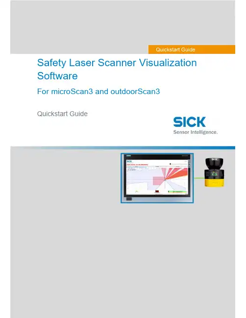
Safety Laser Scanner Visualization SoftwareFor microScan3 and outdoorScan3Quickstart GuideQuickstart GuideInhalt1. Display scanner data in 7 steps (3)Step 1 – Connect Scanner (3)Step 1.1 – Power Supply (3)Step 1.2 – Ethernet Cable (3)Step 2 – Set up Ethernet Connection (4)Step 2.1 – Read out IP address using Safety Designer (4)Step 2.2 – Read out IP address on display of safety laser scanner (4)Step 3 – Download Software (4)Step 4 – Preparing SLS Visualization Software (5)Step 4.1 –Edit “executable” file to correct IP address (5)Step 4.2 – Replace IP address (5)Step 4.3 – Save file (6)Step 5 – Preparing the computer for the network connection. (7)Step 6 – Open the SLS Visualization Software (9)Step 7 – SLS Visualization Software is displayed (9)2. Using the SLS Visualization Software on WinCC – Overview (10)WinCC Professional (TIA Portal) (10)WinCC Advanced (TIA Portal) (11)Quickstart Guide – Safety Laser Scanner Visualization Software This document describes the steps to run the SLS Visualization Software for microScan3 and outdoorScan3.Pre-requisites:Windows PC (Win XP and up).o Note 1: The SLS Visualization Software does not run on Windows CE.W indows CE has reached End of Life Support in 2018; therefore SICK cannotprovide the SLS Visualization Software for Windows CE.o Note 2: Many SIEMENS HMI's using TIA Portal are based on Windows / WinCC → therefore many SIEMENS HMI's are supported.Supported devicesAll microScan3 devices - except all microScan3 Core I/O versionsOnly outdoorScan3 Pro EtherNet IP1. Display scanner data in 7 stepsStep 1 – Connect ScannerFirst, connect the safety laser scanner to the HMI or computer on which the SLS Visualization Software is used.Step 1.1 – Power SupplyConnect scanner to power supply with 24V. Find appropriate cables on .As an example, the following cable can be used for power connection for microScan3 ProPROFINET:Step 1.2 – Ethernet CableConnect safety laser scanner to HMI or computer using an Ethernet cable. Find appropriate cables on . As an example following cable can be used for microScan3 Pro PROFINET :Step 2 – Set up Ethernet ConnectionThe next step is to set up the Ethernet Connection. In order to do this the IP address of the safety laser scanner needs to be known. There are two simple ways to read it out.Step 2.1 – Read out IP address using Safety DesignerOpen Safety Designer, connect to device (e.g. by using USB cable) and see address on pageaddressing.Step 2.2 – Read out IP address on display of safety laser scannerUse the Buttons on the Safety Laser Scanner. (Device Info Network IP address)Step 3 – Download SoftwareClick link to download the SLS Visualization Software:- SICK Internal: Download here:https:///pages/viewpageattachments.action?pageId=393349683&preview=/393349683/393349693/microScan3-VISU-Diagnostics_V1-0.rar- SICK External: receive Secureshare Link by your SICK Contact.When the download is finished open the ZIP file as follows:Unpack ZIP file to afolder of choiceStep 4 – Preparing SLS Visualization SoftwareWhen the file is unzipped, following files should be included:Step 4.1 –Edit “executable” file to correct IP addressThe IP address that is programmed must be edited before starting the THE SLS VISUALIZATION SOFTWARE.Step 4.2 – Replace IP addressA window will open in which the specified IP address must be exchanged by the address of the safety laserscanner. If you do not have this IP address then go back to “Step 2”.Right click on the file "Execute_192_168_1_5.bat " allows editing of the file.Replace the pre-programmed IP address with the actual IP address of the scanner.Step 4.3 – Save fileOnce the IP address is set correctly safe the executable with its new name. The name should include the actual IP addressStep 5 – Preparing the computer for the network connection.Using Windows computers the connection may have to set in the Control panel. See steps below.Open Network andSharing Center.Go to …Ethernet“Go to “Properties”Go to …Internetprotocol, Version 4 (TCP/IPv4)“Enter the IP address andsubnet mask. Subnet mask is the same asthe scanner.Note that this is the IP address ofthe HMI VISU, not of thescanner. Thus: Same subnet, nutdifferent IP address, however insame range. Confirm …OK“.Step 6 – Open the SLS Visualization SoftwareOpen the bat file.Step 7 – SLS Visualization Software is displayedOpen the bat file that was created previously with the actual IP address in itThe VISU tool will open and should automatically connect to the safety laser scanner.2. Using the SLS Visualization Software on WinCC – OverviewWinCC (TIA Portal) is available in different variants WinCC Basic, WinCC Comfort, WinCC Advanced and WinCC Professional. In addition, there are the two runtime systems WinCC Runtime Advanced and WinCC Runtime Professional. The difference between the variants lies primarily in the configurable devices.WinCC Professional (TIA Portal)With WinCC Professional the THE SOFTWARE DIAG tool can be opened with an exe file via a c script. To do this the following code must be written into the script.WinCC Advanced (TIA Portal)To start the HMI VISU DIAG tool the following software is needed on WinCC Advanced: The tool can then be implemented into the WinCC advanced software.The tool can now be displayed via WinCC Advanced.The …diag2“-Button, will start the defined eventHere you can choose at which event an actionshould be executed. Under …Program name“ youhave to link the tool you want to open.。
LECTOR620中文操作手册安装距离和角度扫描器的安装距离是指从扫描器的窗口到条码表面的距离。
每种条码的阅读距离都不同,因此安装过程中阅读距离的确定需要查阅相关型号的技术参数。
例如,对于0.5mm分辨率的条码,其最大的视野范围是175mm×112mm(如右图),对应最大视野范围的安装高度为260mm为了避免条码表面对红光直接的反射,条码阅读器一般不采取垂直于条码表面的安装方式,应倾斜20°安装软件操作步骤(1)首先打开SOPAS 软件,一般安装SOPAS后会出现两个软件图标,一个是SOPAS,一个是SOPAS Single Device,两个是同一个软件,不同的是界面排版不同,推荐使用SOPAS Single Device界面版本(2)进入以下画面,会自动搜寻出两个设备,两个所不同是端口号,一个是以太网主口2112,一个是以太网辅口2111,推荐选择2112(3)若搜寻设备的结果如下图则说明扫描枪IP地址与电脑IP地址不一致,可修改电脑IP或扫描枪IP,注意修改时要保证扫描枪和电脑IP地址前三段一致,最后一段不同,同时保证子网掩码相同(4)修改扫描枪IP地址时,可选自动获取或者使用固定IP,推荐使用固定IP地址用于调试和通讯(5)出现选择画面,勾选尾缀为2112的扫描枪,点击继续,即可进入软件主界面。
(6)进入主界面,现处于运行模式Operation ,界面如下图:(7)调试时切换到编辑模式,点击Edit ,此时读码器连续拍照,光源一致闪烁,显示实时图像,右侧有8电脑IP 地址扫描枪IP 地址个参数栏,常用的参数栏如下:(8)第一项参数Camera & Illumination 相机和光源设定:调试要点:图像一定要清晰,根据实际情况调节曝光时间,增益和对比度获取稳定的阅读效果(9)第二项参数Codes 条码设定:本产品可同时阅读一维条码,二维PDF417码,二维码,根据所要读取的条码种类勾选相应的码制1. 相机和光源设定2. 条码种类设定3. 触发设定4. 通讯接口和信号输出设定5. 输出格式设定(10)以上图像和条码设定也可通过自学习方式完成,点击Auto Setup自动设定,如下:(11)点击后显示如下画面,首先调整Reading Distance阅读距离使图像聚焦清晰,调整Shutter time曝光时间使图像变亮,在条码的位置拖动鼠标画一个区域覆盖条码,点击继续进入自学习过程(12)学习成功后如下画面,点击继续;若自学习不成功则会显示Fail,此时可进入软件手动调整参数(13)显示如下实时阅读画面,点击结束完成自学习(14)第三项Trigger & Digital Input触发和输入信号设定,本产品触发读码器方式有很多种,常用是Sensor/Input 1,由外部接入开关量信号触发读码器开始阅读,结束阅读也有多种方式并且可以组合使用,满足任意条件均可结束阅读(15)第四项Interface & Digital Output 通讯接口和信号输出设定,常用通讯方式是串口RS232和以太网(16)串口通讯设置:点开Serial Host ,通常情况下无需修改参数,默认参数即可,但要注意波特率Baud rate 要和上位机一样触发开始串口 输出信号(17)以太网通讯设置:点开Ethernet Host,a.当需要设扫描枪为服务器端时则选择Server模式,上位机需要输入扫描枪的IP地址和端口号,其中端口号可根据需要修改,默认为2112;b.当需要设定扫描枪为客户端时则选择Client模式,此时需要输入上位机的IP地址和端口号,其中端口号可根据需要修改,默认为2112(18)扫描枪支持两路输出,以设定Output/Result 1输出信号为例,可设定成功读取Good Read或者读不到No Read时输出信号,输出电压默认为24V PNP型,也可通过反转功能变成0V有效,NPN型(19)第五项Data Processing 数据处理设定,扫描枪输出的数据格式可根据需要灵活编辑,点击Data Processing 中的Output Format1选项,默认输出格式如下图即“如果成功读取则输出条码内容,否则输出NoRead ”,可以在此处编辑,例如在条码后加入回车换行(20)数据输出格式也可通过设置向导Wizard 完成,点击Wizard 选择好所要的格式后点击继续(21)设定所需要读的码的最多和最少数量,点击继续码可在条码之间加分隔符Code Separator,如空格,斜杠等,设置完成后点击结束(23)设定完成后切换为运行模式Operation ,点击Operation 即可(24)点击参数下载和永久保存,将参数保存在扫描器中:(25)本软件自带数据接收终端,显示所读取到的数据,可用于调试串口和以太网通讯是否正常,点击数据终端Terminal ,以以太网通讯为例操作如下:若是串口则选择用户自定义连接。
User manual: Information systemThis document describes the usage of SICK’s information system / reporting system in Pool4Tool. This system provides KPIs and reports which can be used by both SICK and its suppliers.User manual: Information system (1)1.Introduction (2)2.Accessing the information system (3)2.1.For SICK employees (3)2.2.For suppliers (3)3.Functions in the information system (4)3.1.navigation (4)3.2.Report types (4)3.2.1.Charts (4)3.2.2.Data table (5)3.3.Select data (setting filters) (5)3.4.Printing data (7)3.5.Exporting data (Excel) (8)1. IntroductionThe information system provides KPIs to measure and control the procurement processes of SICK.2.1. For SICK employeesYou can find the information system in Pool4Tool under CRM / SRM and then information system. https:///login.php2.2. For suppliersSuppliers can find the information system at the bottom of the menu-box on the left side of the entry page at the SICK supplier portal. https:///portal/sick/login.php3.1. navigationTo open a specific report, please select it in the menu-box.3.2. Report typesTwo types of reports can be found in the information system.3.2.1. ChartsCharts can be identified by the blue symbol (e. g. turnover development) – data will be displayed in graphical format (bar chart, line chart…)3.2.2. Data tableReports of this type display data in a table format and can provide more detailed information than charts. This data can be downloaded to Excel in order to perform further analysis (see chapter 3.4).3.3. Select data (setting filters)For each report a filter is available. This filter allows you to adapt the displayed data to your current requirements (e. g. turnover of supplier X, delivery performance of material group Y…). As long as no filter is defined, all available data will be displayed.By default, the filter is invisible in order to provide more space for the reporting data. In order to show the filter, please click on the plus symbol in the filter box (see red square in previous picture).Now it is possible to define a combination of filter criterias. Use the button “Display” to activate your filter. The following filter types are available:•Single selection (e. g. Division): Select one value in a list•Multiple selection (e. g. Warengruppe): Select one or several values in a list (use Ctrl + MouseClick or Shift + MouseClick).•Free filter (e.g. Lieferantennummer): Any value can be entere as filter criteria. To define more than one value, a semicolon can be used. Use …53052;53011“ to display all which contains either 53052 or 53011 (or both).•Date filter (e.g. Rechnungsdatum): A period of time can be selected. The green icons help you to select a valid date.Some hints:•All filters are used as so called LIKE-filters (asterix search): If you search for supplier name …test“, suppliers like “abctest” oder “testabc” will be found.•Use the reset button to delete all defined filter criterias.•To reset only on filter criteria, please delete its value or select --- in the provided list.•Filter criteria will be saved if you change from one report to another (as long as the filter field is also available in the other report).As soon as you click on “Display”, the filter will be closed and the displayed data will be adapted to the defined filter. You can see the filter criterias in the blue box above the data.3.4. Printing dataYou can use the function “Print” of your web browser.Alternatively, you can right click on a certain chart to convert it to an image or to print it directly.3.5. Exporting data (Excel)Reports of the type “data table” provide an Excel icon on the top right corner. Click on it to download the table to Excel.。
OLS20轨迹导引传感器所说明的产品OLS20制造商SICK AGErwin-Sick-Str.179183 Waldkirch, Germany德国法律信息本文档受版权保护。
其中涉及到的一切权利归西克公司所有。
只允许在版权法的范围内复制本文档的全部或部分内容。
未经西克公司的明确书面许可,不允许对文档进行修改、删减或翻译。
本文档所提及的商标为其各自所有者的资产。
© 西克公司版权所有。
原始文档本文档为西克股份公司的原始文档。
2操作指南 | OLS208024411.1IY1/2023/04/24 | SICK如有更改,恕不另行通知内容内容1关于本文档的 (5)1.1更多信息 (5)1.2符号和文档约定 (5)2安全信息 (6)2.1规定用途 (6)2.2违规使用 (6)2.3关于 UL 认证的提示 (6)2.4责任范围 (6)2.5对专业人员和操作人员的要求 (7)2.6危险提示与作业安全 (7)2.7维修 (7)3产品说明 (8)3.1产品识别 (8)3.2产品特点 (9)4运输和仓储 (10)4.1运输 (10)4.2运输检查 (10)4.3储存环境 (10)5装配 (11)5.1安装准备 (11)5.2安装传感器 (11)6电气安装 (14)6.1安全性 (14)6.2接口的引脚分配 (15)6.3连接工作电压 (16)6.4CAN 接口 (16)7调试 (17)7.1调试步骤概览 (17)7.2首次运行传感器 (17)7.3使用 CANopen 调试的第一步 (17)7.4使用 Modbus RTU 调试的第一步 (20)8操作 (22)8.1通过 CANopen 操作 (22)8.2通过 Modbus RTU 操作 (27)8.3有关操作的一般提示 (30)9维护 (31)9.1清洁 (31)8024411.1IY1/2023/04/24 | SICK操作指南 | OLS203如有更改,恕不另行通知内容9.2维护 (31)9.3维修 (31)10停机 (32)10.1停用 (32)11故障排除 (33)11.1可能的错误指示 (33)12技术数据 (34)12.1光学元件/特性 (34)12.2供电 (34)12.3接口 (34)12.4输出 (34)12.5环境条件 (35)12.6设计结构 (35)13附件 (36)14许可证 (37)15附件 (38)15.1合规性和证书 (38)4操作指南 | OLS208024411.1IY1/2023/04/24 | SICK如有更改,恕不另行通知1关于本文档的1.1更多信息如需查看产品页面的更多信息,请访问 SICK Product ID:/{P/N}/{S/N}。
ER 12Dual pushbuttonDescribed productER 12ManufacturerSICK AGErwin-Sick-Str. 179183 WaldkirchGermanyLegal informationThis work is protected by copyright. Any rights derived from the copyright shall bereserved for SICK AG. Reproduction of this document or parts of this document isonly permissible within the limits of the legal determination of Copyright Law. Any modi‐fication, abridgment or translation of this document is prohibited without the expresswritten permission of SICK AG.The trademarks stated in this document are the property of their respective owner.© SICK AG. All rights reserved.Original documentThis document is an original document of SICK AG.2O P E R A T I N G I N S T R U C T I O N S | ER 128027704/1HJA/2022-10-24 | SICKSubject to change without noticeCONTENTSContents1About this document (4)2On safety (5)2.1Application (5)3Product description (6)3.1Items supplied (6)3.2Function (6)4Mounting (7)5Connection (8)6Tests before the initial commissioning (9)7Periodic technical inspections (10)8What to do in case of a malfunction (11)9Uninstalling (12)10Disposal (13)11Conformities and certificates (14)11.1EU declaration of conformity (14)11.2UK declaration of conformity (14)12Technical data (15)12.1Data sheet (15)12.2Dimensional drawings (15)13Ordering information (16)8027704/1HJA/2022-10-24 | SICK O P E R A T I N G I N S T R U C T I O N S | ER 123 Subject to change without notice1 ABOUT THIS DOCUMENT1About this documentThese operating instructions are original operating instructions.4O P E R A T I N G I N S T R U C T I O N S | ER 128027704/1HJA/2022-10-24 | SICKSubject to change without noticeON SAFETY 2 2On safetyRead these operating instructions carefully and keep them in a safe place.The operating instructions are to be provided to the person who is installing the dualpushbutton.DANGERb Always note and follow the warnings below!•Before starting the installation, electrically isolate system and device!•The dual pushbutton is not allowed to be bypassed, removed or rendered ineffec‐tive in any other manner!•Incorrect installation or tampering can result in damage to the machine andworkpiece!•The reset and override functions are not allowed to be used as a replacement forprotective measures or other safety functions, instead they should be designed asadditional protective measures.•The reset and override functions are not allowed to degrade the effectiveness ofprotective devices or other devices with safety functions.•Based on a risk analysis, the designer must ensure that the dual pushbutton —depending on the application — achieves the required level of safety (SIL, SILCL orPL) in combination with the control system.2.1ApplicationThe national/international rules and regulations apply to the installation, commission‐ing, use and periodic technical inspections of the dual pushbutton, in particular:•EMC directive•safety regulations•work safety regulations and safety rulesManufacturers and operators of the machine on which the dual pushbutton is used areresponsible for obtaining and observing all applicable safety regulations and rules.Correct use includes observance of the applicable requirements on installation andoperation, in particular:•EN 60947-5-1•EN ISO 138491Correct use also includes the regular monitoring of the dual pushbutton by specialistpersonnel.The product may be used in safety functions.8027704/1HJA/2022-10-24 | SICK O P E R A T I N G I N S T R U C T I O N S | ER 125 Subject to change without notice3Product descriptionThe dual pushbutton consists of a compact housing with a plug connector M12 and twoilluminated pushbuttons. Labeled inserts as well as covers are included in the scope ofdelivery. The designer can choose the button assignment as necessary to suit the placeof use. A hazard-free application must be ensured with the aid of a risk assessment.On the usage of the device as a reset pushbutton or override pushbutton, the followingis to be noted:Reset prevents the unexpected starting of the machine, above all in applications inwhich there are persons in the hazardous area but their presence in the hazardousarea is not detected by the protective device.Override is a manual triggering of muting after an error in the muting conditions. Bybriefly pressing the override pushbutton the protective device (muting) is overridden,the system moved clear or the error-free state established.3.1Items supplied•dual pushbutton •retaining clip • 6 covers (blue, black, green, yellow, 2× transparent)•8 labeled inserts (START, RESET, ON, LOCK, UNLOCK, RESET/OVERRIDE, OVER‐RIDE, TEACH)NOTE Only press on cover after mounting!Other mounting material (screws, dowels, sliding nut) not included.3.2FunctionPress and release the pushbuttons.3 PRODUCT DESCRIPTION6O P E R A T I N G I N S T R U C T I O N S | ER 128027704/1HJA/2022-10-24 | SICKSubject to change without notice4MountingDANGER Select a suitable installation location:b Mount the dual pushbutton such that it can be reached easily!b Mount the dual pushbutton in such a way that the hazardous area is completely visible when the dual pushbutton is used.In practice it is recommended to mount the dual pushbutton vertically (connecting cable downward).How to mount the dual pushbutton:1.Mounting on profile rail: Insert sliding nut in profile (sliding nut not included).Or:Wall mounting: Drill two mounting holes in the mounting plate.2.Fasten retaining clip.3.Fit housing to the side of the retaining spring, pull against spring pressure and press on. The dual pushbutton engages.4.Optional: Fit labeled inserts in the required covers.5.Press covers onto the pushbuttons to engage them. On the usage of labeledinserts, pay attention to legible alignment.6.Connect connecting cable to the connection plug. Pay attention to the permissible electrical and mechanical data (see "Technical data", page 15).MOUNTING 48027704/1HJA/2022-10-24 | SICKO P E R A T I N G I N S T R U C T I O N S | ER 127Subject to change without notice5 CONNECTION5ConnectionTable 1: Pin assignment ER12-SD5E88O P E R A T I N G I N S T R U C T I O N S | ER 128027704/1HJA/2022-10-24 | SICKSubject to change without noticeTESTS BEFORE THE INITIAL COMMISSIONING 6 6Tests before the initial commissioningMechanical functional check•Are there any signs of damage to the exterior of the dual pushbutton?•Is the housing securely engaged on the retaining clip?•Is the connecting cable securely fastened?Electrical functional check:1.Stop machine.2.Ensure there is no person in the hazardous area.3.Actuate dual pushbutton.4.Check whether the dual pushbutton performs correctly the intended functions.WARNINGOn the usage of the reset function, it must only be possible to restart the machine afterthe actuation of the dual pushbutton!8027704/1HJA/2022-10-24 | SICK O P E R A T I N G I N S T R U C T I O N S | ER 129 Subject to change without notice7 PERIODIC TECHNICAL INSPECTIONS7Periodic technical inspectionsMake regular checks to ensure correct, long-term function. The inspection interval isto be defined by the machine designer based on the risk assessment. However, it isrecommended the responsible safety officer triggers the dual pushbutton at least oncea year for test purposes and to check for correct function:•mechanical and electrical function check as per chapter 6•no tampering or damage apparent•no loose connections10O P E R A T I N G I N S T R U C T I O N S | ER 128027704/1HJA/2022-10-24 | SICKSubject to change without noticeWHAT TO DO IN CASE OF A MALFUNCTION 8 8What to do in case of a malfunctionDANGERIn case of mechanical overload or the action of external forces, the dual pushbuttonmay be damaged and its function degraded.b Remove the cause.b In this case undertake a function check as per chapter 6.b Replace the device, if necessary.8027704/1HJA/2022-10-24 | SICK O P E R A T I N G I N S T R U C T I O N S | ER 1211 Subject to change without notice9 UNINSTALLING9UninstallingWARNINGElectrically isolate the system and device prior to uninstalling!b Disconnect connecting cable from the plug connector.b Using a screwdriver pull up the slide (Mounting, Step 2).b Release housing from retaining clip.12O P E R A T I N G I N S T R U C T I O N S | ER 128027704/1HJA/2022-10-24 | SICKSubject to change without noticeDISPOSAL 10 10DisposalApproachb Always dispose of unusable devices in accordance with national waste disposalregulations.Complementary informationSICK will be glad to help you dispose of these devices on request.8027704/1HJA/2022-10-24 | SICK O P E R A T I N G I N S T R U C T I O N S | ER 1213 Subject to change without notice11 CONFORMITIES AND CERTIFICATES11Conformities and certificatesYou can obtain declarations of conformity, certificates, and the current operatinginstructions for the product at . To do so, enter the product part numberin the search field (part number: see the entry in the “P/N” or “Ident. no.” field on thetype label).11.1EU declaration of conformityExcerptThe undersigned, representing the manufacturer, herewith declares that the product isin conformity with the provisions of the following EU directive(s) (including all applicableamendments), and that the standards and/or technical specifications stated in the EUdeclaration of conformity have been used as a basis for this.•ROHS DIRECTIVE 2011/65/EU•LV DIRECTIVE 2014/35/EU11.2UK declaration of conformityExcerptThe undersigned, representing the following manufacturer herewith declares that thisdeclaration of conformity is issued under the sole responsibility of the manufacturer.The product of this declaration is in conformity with the provisions of the followingrelevant UK Statutory Instruments (including all applicable amendments), and therespective standards and/or technical specifications have been used as a basis.•Restriction of the Use of Certain Hazardous Substances in Electrical and Elec‐tronic Equipment Regulations 2012•Electrical Equipment (Safety) Regulations 201614O P E R A T I N G I N S T R U C T I O N S | ER 128027704/1HJA/2022-10-24 | SICKSubject to change without notice12Technical data12.1Data sheetTable 2: Technical data dual pushbutton ER12-SD5E8Enclosure rating IP65 (EN 60529)Protection classIII (EN 61 140)Ambient operating temperature –25 … +70 °C Storage temperature –25 … +80 °CSwitching elements 2 normally open contacts (EN 6094751)B 10D value1 × 106 switching operations (EN ISO 138491)MTTF D (Mean time to failure)27.945 (at switching frequency C = 1/d, EN ISO 13849-1)Electrical/mechanical service life (at +20 °C) 1 × 10⁶ switching operations Max. bounce time <10 ms Rated current I e 5 mA … 100 mA Rated voltage U e5 V … 30 V Power consumption, max.250 mWHousing material PBT (polybutylene terephthalate)Contact materialAgNiIllumination connection dual pushbutton Supply voltage 30 V AC/DC Power consumption14 mA (at 24 V)12.2Dimensional drawingsFigure 1: Dimensional drawing dual pushbutton ER12-SD5E8 (mm)TECHNICAL DATA 128027704/1HJA/2022-10-24 | SICK O P E R A T I N G I N S T R U C T I O N S | ER 1215Subject to change without notice13 ORDERING INFORMATION13Ordering informationTable 3: Part numbers and type codes dual pushbutton ER12-SD5E816O P E R A T I N G I N S T R U C T I O N S | ER 128027704/1HJA/2022-10-24 | SICKSubject to change without noticeORDERING INFORMATION 138027704/1HJA/2022-10-24 | SICK O P E R A T I N G I N S T R U C T I O N S | ER 1217 Subject to change without notice13 ORDERING INFORMATION18O P E R A T I N G I N S T R U C T I O N S | ER 128027704/1HJA/2022-10-24 | SICKSubject to change without noticeORDERING INFORMATION 138027704/1HJA/2022-10-24 | SICK O P E R A T I N G I N S T R U C T I O N S | ER 1219 Subject to change without noticeDetailed addresses and further locations at AustraliaPhone +61 (3) 9457 0600 1800 33 48 02 – tollfree E-Mail **************.au AustriaPhone +43 (0) 2236 62288-0 ********************Belgium/LuxembourgPhone +32 (0) 2 466 55 66 ******************BrazilPhone +55 11 3215-4900 ************************.br CanadaPhone +1 905.771.1444 ************************Czech RepublicPhone +420 234 719 500 ******************ChilePhone +56 (2) 2274 7430 E-Mail **************ChinaPhone +86 20 2882 3600 E-Mail *******************.cn DenmarkPhone +45 45 82 64 00 ******************FinlandPhone +358-9-25 15 800 ******************FrancePhone +33 1 64 62 35 00 ******************GermanyGreecePhone +30 210 6825100 E-Mail ***************.gr Hong KongPhone +852 2153 6300 E-Mail ************.hkHungaryPhone +36 1 371 2680 *************************IndiaPhone +91-22-6119 8900 *************************IsraelPhone +972 97110 11***************************ItalyPhone +39 02 27 43 41 ******************JapanPhone +81 3 5309 2112 *********************MalaysiaPhone +603-8080 7425 *************************MexicoPhone +52 (472) 748 9451 *********************NetherlandsPhone +31 (0) 30 229 25 44 ******************New ZealandPhone +64 9 415 0459 0800 222 278 – tollfree E-Mail *************.nz NorwayPhone +47 67 81 50 00 ******************PolandPhone +48 22 539 41 00 ******************RomaniaPhone +40 356-17 11 20 E-Mail **************RussiaPhone +7 495 283 09 90 ******************SingaporePhone +65 6744 3732 ************************SlovakiaPhone +421 482 901 201 *********************SloveniaPhone +386 591 78849 ********************South AfricaPhone +27 10 060 0550****************************.za South KoreaPhone +82 2 786 6321/4 ************************SpainPhone +34 93 480 31 00 ******************SwedenPhone +46 10 110 10 00 ******************SwitzerlandPhone +41 41 619 29 39 *********************TaiwanPhone +886-2-2375-6288 ********************.tw ThailandPhone +66 2 645 0009 ************************TurkeyPhone +90 (216) 528 50 00 *******************.tr +44 (0)17278 31121************.uk +1 800.325.7425 *************+65 6744 3732******************United Arab EmiratesPhone +971 (0) 4 88 65 878E-Mail ***************United KingdomPhone E-Mail USAPhone E-Mail VietnamPhone E-Mail Phone +49 (0) 2 11 53 010E-Mail ************SICK AG | Waldkirch | Germany | 8027704/1H J A /2022-10-24/e n。
i n d u s t r Y o V e r V i e WCourier, express, parCel and postal appliCations eFFiCientlY solVed/VMs6x00_7x00 /VMs4x00_5x00/ruler3000g /tdC /tiM3xx8019595/2021-09-27 ∙ G I C L A /I T L ∙ P r e U S m o d e n 51siCK aG | Waldkirch | Germany | siCK at a GlanCe siCK is a leading manufacturer of intelligent sensors and sensor solutions for industrial applications. With more than 10,400 employees and over 50 subsidiaries and equity investments as well as numerous agen-cies worldwide, siCK is always close to its customers. a unique range of products and services creates the perfect basis for controlling processes securely and efficiently, protecting individuals from accidents, and preventing damage to the environment.siCK has extensive experience in various industries and understands their processes and requirements. With intelligent sensors, siCK delivers exactly what the customers need. in application centers in europe, Asia, and North America, system solutions are tested and optimized in accordance with customer specifica -tions. all this makes siCK a reliable supplier and development partner.Comprehensive services round out the offering: siCK lifetime services provide support throughout the machine life cycle and ensure safety and productivity.That is “Sensor Intelligence.”Worldwide presence:australia, austria, Belgium, Brazil, Canada, Chile, China, Czech republic, denmark, Finland, France, Germany, Great Britain, Hungary, Hong Kong, india, israel, italy, Japan, Malaysia, Mexico, netherlands,new Zealand, norway, poland, romania, russia, singapore, slovakia, slovenia, south africa, south Korea, spain, sweden, switzerland, taiwan, thailand, turkey, united arab emirates, usa, Vietnam.detailed addresses and further locations - 。
LECTOR620中文操作手册
安装距离和角度
扫描器的安装距离是指从扫描器的窗口到条码表面的距离。
每种条码的阅读距离都不同,因此安装过程中阅读距离的确定需要查阅相关型号的技术参数。
例如,对于0.5mm分辨率的条码,其最大的视野范围是175mm×112mm(如右图),对应最大视野范围的安装高度为260mm
为了避免条码表面对红光直接的反射,条码阅读器一般不采取垂直于条码表面的安装方式,应倾斜20°安装
软件操作步骤
(1)首先打开SOPAS 软件,一般安装SOPAS后会出现两个软件图标,一个是SOPAS,一个是SOPAS Single Device,两个是同一个软件,不同的是界面排版不同,推荐使用SOPAS Single Device界面版本
(2)进入以下画面,会自动搜寻出两个设备,两个所不同是端口号,一个是以太网主口2112,一个是以太网辅口2111,推荐选择2112
(3)若搜寻设备的结果如下图则说明扫描枪IP地址与电脑IP地址不一致,可修改电脑IP或扫描枪IP,注意修改时要保证扫描枪和电脑IP地址前三段一致,最后一段不同,同时保证子网掩码相同
(4)修改扫描枪IP地址时,可选自动获取或者使用固定IP,推荐使用固定IP地址用于调试和通讯
(5)出现选择画面,勾选尾缀为2112的扫描枪,点击继续,即可进入软件主界面。
(6)进入主界面,现处于运行模式Operation ,界面如下图:
(7)调试时切换到编辑模式,点击Edit ,此时读码器连续拍照,光源一致闪烁,显示实时图像,右侧有8
电脑IP 地址
扫描枪IP 地址
个参数栏,常用的参数栏如下:
(8)第一项参数Camera & Illumination 相机和光源设定:
调试要点:图像一定要清晰,根据实际情况调节曝光时间,增益和对比度获取稳定的阅读效果
(9)第二项参数Codes 条码设定:本产品可同时阅读一维条码,二维PDF417码,二维码,根据所要读取的条码种类勾选相应的码制
1. 相机和光源设定
2. 条码种类设定
3. 触发设定
4. 通讯接口和信号输出设定
5. 输出格式设定
(10)以上图像和条码设定也可通过自学习方式完成,点击Auto Setup自动设定,如下:
(11)点击后显示如下画面,首先调整Reading Distance阅读距离使图像聚焦清晰,调整Shutter time曝光时间使图像变亮,在条码的位置拖动鼠标画一个区域覆盖条码,点击继续进入自学习过程
(12)学习成功后如下画面,点击继续;若自学习不成功则会显示Fail,此时可进入软件手动调整参数
(13)显示如下实时阅读画面,点击结束完成自学习
(14)第三项Trigger & Digital Input触发和输入信号设定,本产品触发读码器方式有很多种,常用是Sensor/Input 1,由外部接入开关量信号触发读码器开始阅读,结束阅读也有多种方式并且可以组合使用,满足任意条件均可结束阅读
(15)第四项Interface & Digital Output 通讯接口和信号输出设定,常用通讯方式是串口
RS232和以太网
(16)串口通讯设置:
点开Serial Host ,通常情况下无需修改参数,默认参数即可,但要注意波特率Baud rate 要和上位机一样
触发开始
串口 输出信号
(17)以太网通讯设置:点开Ethernet Host,
a.当需要设扫描枪为服务器端时则选择Server模式,上位机需要输入扫描枪的IP地址和端口号,其中端口号可根据需要修改,默认为2112;
b.当需要设定扫描枪为客户端时则选择Client模式,此时需要输入上位机的IP地址和端口号,其中端口号可根据需要修改,默认为2112
(18)扫描枪支持两路输出,以设定Output/Result 1输出信号为例,可设定成功读取Good Read或者读不到No Read时输出信号,输出电压默认为24V PNP型,也可通过反转功能变成0V有效,NPN型
(19)第五项Data Processing 数据处理设定,扫描枪输出的数据格式可根据需要灵活编辑,点击Data Processing 中的Output Format1选项,默认输出格式如下图即“如果成功读取则输出条码内容,否则输出NoRead ”,可以在此处编辑,例如在条码后加入回车换行
(20)数据输出格式也可通过设置向导Wizard 完成,点击Wizard 选择好所要的格式后点击继续
(21)设定所需要读的码的最多和最少数量,点击继续
码可在条码之间加分隔符Code Separator,如空格,斜杠等,设置完成后点击结束
(23)设定完成后切换为运行模式Operation ,点击Operation 即可
(24)点击参数下载和永久保存,将参数保存在扫描器中:
(25)本软件自带数据接收终端,显示所读取到的数据,可用于调试串口和以太网通讯是否正常,点击数据终端Terminal ,以以太网通讯为例操作如下:
若是串口则选择用户自定义连接。