遥控窗帘说明书
- 格式:doc
- 大小:184.00 KB
- 文档页数:14
智能窗帘使用说明书欢迎使用智能窗帘,本说明书将为您详细介绍智能窗帘的组装、安装以及使用方法。
一、产品组装1. 打开包装,将智能窗帘的各个零部件按照配件清单逐一检查,确保所有配件完整。
2. 将窗帘轨道的轨道头与轨道尾按照指示对准,插入并扣紧。
3. 将窗帘布料通过窗帘轨道的滑块穿过,确保布料平整无皱褶。
4. 调整窗帘布料的长度适合窗户大小,使用剪刀剪掉多余的部分。
二、安装方法1. 在窗户顶部选择一个适当的位置,用尺子量取标准长度,标记出安装点。
2. 使用螺丝刀将窗帘轨道固定在预先标记的位置上,确保安装牢固。
3. 将窗帘电机与窗帘轨道的连接件组装在一起,并确保连接紧密。
4. 将窗帘电机接通电源,并在智能窗帘配套手机应用程序中进行配对。
三、使用方法1. 下载并打开智能窗帘配套手机应用程序,注册并登录您的账户。
2. 将手机连接到智能窗帘的Wi-Fi信号,确保手机与智能窗帘成功连接。
3. 在应用程序上选择相应的窗帘,您可以通过拖动手势控制窗帘的开合。
4. 应用程序中还提供了定时功能,您可以设置特定时间让窗帘自动开启或关闭。
5. 智能窗帘还支持语音控制,您可以通过语音指令告诉智能助理打开或关闭窗帘。
四、注意事项1. 在安装窗帘时,请确保窗户框架结构牢固且平整,以免影响窗帘的正常使用。
2. 请勿将智能窗帘暴露在潮湿的环境中,以免损坏电子元件。
3. 在搬动窗边等操作过程中,请避免过度幅度的操作,以免拉伸窗帘轨道导致损坏。
4. 如果智能窗帘长时间不使用,请关闭电源以节省能源并延长电池寿命。
五、售后服务如您在使用智能窗帘的过程中遇到任何问题,请随时联系我们的售后服务团队。
我们将竭诚为您提供解决方案和技术支持。
感谢您选择使用智能窗帘,我们相信它将为您带来舒适和便利的居家体验。
如需更多帮助,请参阅产品附带的详细说明书或联系我们的客服部门。
祝您生活愉快!。

电动窗帘遥控器操作手册一、操作前准备在开始操作电动窗帘遥控器之前,请确保以下准备工作已完成:1.检查电动窗帘遥控器电池电量是否充足,若电池电量不足,请及时更换新电池。
2.确认电动窗帘电源已连接并通电,窗帘电源开关处于打开状态。
3.确保电动窗帘安装位置通畅,窗帘布料无阻碍。
二、基本操作1.打开窗帘按下遥控器上的“上升”按钮,窗帘将缓慢升起,当窗帘到达所需位置时,松开按钮,窗帘将停止运动。
2.关闭窗帘按下遥控器上的“下降”按钮,窗帘将缓慢下降,当窗帘完全关闭时,松开按钮,窗帘停止运动。
3.停止窗帘运动在窗帘运动过程中,按下遥控器上的“停止”按钮,窗帘将立即停止运动。
三、高级操作1.定时控制功能遥控器上通常具有定时控制功能,可设置窗帘的升降时间。
操作方法如下:1.1按下遥控器上的“定时”按钮,进入定时设置模式。
1.2通过遥控器上的“上升”和“下降”按钮,设置窗帘升降的时间。
1.3按下“确定”按钮,保存设置。
2.遥控距离扩展如果您发现遥控器的信号范围有限,您可以尝试以下操作来扩展遥控距离:2.1重新装入或更换遥控器电池。
2.2避免与其他电子设备(如手机、无线路由器等)的电磁干扰。
2.3更换电动窗帘遥控器天线。
2.4增加遥控器继电器或信号放大器来增强信号。
3.一键操作功能一些电动窗帘遥控器具备一键操作功能,可实现多个窗帘的同步控制。
具体方法如下:3.1首先选择要控制的窗帘编号。
3.2按下遥控器上的“一键”按钮。
3.3所有选定的窗帘将同步执行相同的操作。
四、注意事项在操作电动窗帘遥控器时,请注意以下事项,以确保安全有效的使用:1.遥控器应放置在儿童无法触及的位置。
2.请勿将遥控器置于高温、潮湿或阳光直射的环境中。
3.请勿将遥控器撕开或强行拆卸。
4.遥控器使用过程中,如发现异常情况(如遥控距离明显减弱等),应及时联系专业维修人员进行检修。
五、维护与保养如果您希望您的电动窗帘遥控器保持良好的工作状态,请遵循以下维护与保养准则:1.定期清洁遥控器表面,使用柔软的干布擦拭。
鸿雁电动窗帘操作说明1. 引言鸿雁电动窗帘是一种现代化、智能化的窗帘产品,通过电动装置实现窗帘的开合。
本操作说明将详细介绍鸿雁电动窗帘的使用方法,包括控制器的使用、遥控器的操作以及与智能家居系统的连接。
2. 控制器的使用鸿雁电动窗帘的控制器是窗帘系统的核心部件,用于手动控制窗帘的开合。
控制器通常安装在墙壁上,方便用户随时控制窗帘。
2.1 控制器的外观控制器外观简洁大方,采用触摸屏设计,屏幕显示窗帘的状态和操作界面。
控制器配有几个常用的功能按钮,如开、关、停等。
2.2 控制器的操作•开启窗帘:按下控制器上的“开”按钮,窗帘将开始向开启方向运动,直到完全开启。
•关闭窗帘:按下控制器上的“关”按钮,窗帘将开始向关闭方向运动,直到完全关闭。
•停止窗帘:按下控制器上的“停”按钮,窗帘将停止运动,并保持当前位置。
3. 遥控器的操作除了使用控制器,用户还可以使用遥控器对鸿雁电动窗帘进行操作。
遥控器具有更大的灵活性和便携性,用户可以随时随地控制窗帘。
3.1 遥控器的外观遥控器小巧轻便,便于携带。
遥控器上配有开、关、停等按钮,以及数字键和模式选择键。
3.2 遥控器的操作•开启窗帘:按下遥控器上的“开”按钮,窗帘将开始向开启方向运动,直到完全开启。
•关闭窗帘:按下遥控器上的“关”按钮,窗帘将开始向关闭方向运动,直到完全关闭。
•停止窗帘:按下遥控器上的“停”按钮,窗帘将停止运动,并保持当前位置。
•预设位置:遥控器上的数字键可以设置窗帘的预设位置,用户可以通过按下数字键设置窗帘的特定位置,方便日常使用。
•模式选择:遥控器上的模式选择键可以切换窗帘的工作模式,如手动模式、自动模式、定时模式等。
4. 与智能家居系统的连接鸿雁电动窗帘还支持与智能家居系统的连接,通过智能家居系统,用户可以通过手机或语音控制窗帘的开合。
4.1 连接方式•Wi-Fi连接:通过将窗帘控制器与家庭Wi-Fi网络连接,用户可以使用手机APP控制窗帘的开合。
ZBCurtainZigbee Smart Curtain Motor产品介绍安装设备前,请务必先扫码观看设备安装教程指示灯配对按钮开关键(滑动) Type-C接口(R)设备不支持罗马杆及弯曲窗帘轨道。
确保窗帘轨道顶部空间大于2mm,且轨道宽度小于40mm,否则无法安装C型夹。
功能特点SONOFF ZBCurtain是一款Zigbee智能窗帘电机,可以将家中窗帘智能化,具有远程控制、本地遥控、语音控制、手拉启停等功能,您可以按照百分比精准打开或关闭窗帘,也可以通过智能场景、定时器使窗帘更加自动化。
远程控制场景联动手拉启/停智能定时/延时分享控制本地遥控语音控制安装窗帘电机1.打开卷盘,取出链子2.先把主机扣在左侧C型夹上,并向下扣紧如链子长度不够,可将绑好的链子拆出来使用。
4.将副机扣在右侧C型夹上, 并向下扣紧5.按住夹子(R)按钮同时向下拉紧链子安装窗帘夹子装夹子前,先关上窗帘。
请前往应用商店、Google Play Store或Apple App Store搜索"易微联"进行下载。
2.添加 SONOFF Zigbee网关2.单开窗帘确保网关版本为:ZBBridge-P V1.1.0及以上,ZBBridge V1.6.0及以上4.有效距离验证3.将窗帘电机添加至Zigbee网关打开eWeLink App,选择要连接的网关,点击 "添加" 子设备。
然后将窗帘电机开机,开机后LED指示灯呈 “绿色慢闪”状态,此时设备进入配对模式,等待设备添加,添加成功后设备LED指示灯会常亮3秒。
30秒内没配对成功,窗帘电机将退出配对模式,如需再次进入,请长按窗帘电机配对按键5秒直到LED指示灯呈“绿色慢闪”状态即可。
在选定的设备安装位置,短按设备的配对按键,设备指示灯双闪,表明该设备和Zigbee网络下的设备(路由设备或网关)处于有效通讯距离。
设置开关窗行程点1. 开窗行程点设置同时按住遥控器“开窗+暂停”按键,待窗帘移动至开窗时需要停下的位置松开按键即可。
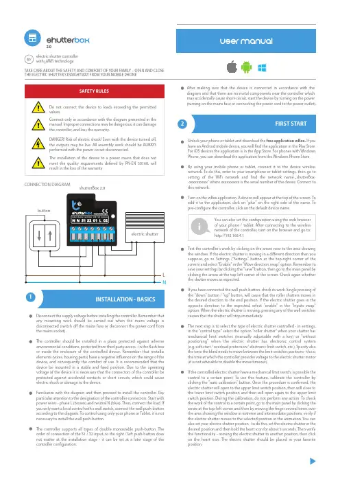
Test the controller’s work by clicking on the arrow near to the area showing the window. If the electric shutter is moving in a di erent direction than you suppose, go to Settings ("Settings" button at the top-right corner of the screen) and select "Enable" in the "Move direction swap" option. Remember to save your settings by clicking the "save" button, then go to the main panel by clicking the arrow at the top-left corner of the screen. Check again whether the shutter moves as expected.If you have connected the wall push-button, check its work. Single pressing of the "down" button / "up" button, will cause that the roller shutters moves in the desired direction to the end position. If the electric shutter goes in the opposite direction to the expected, select "enable" in the "Inputs swap" option. When the electric shutter is moving, pressing any of the wall switches causes that the shutter will stop immediately.The next step is to select the type of electric shutter controlled - in settings, in the "control type" select the option "roller shutter" when your shutter has mechanical limit switches (manually adjustable with a key) or "withoutpositioning" when the electric shutter has electronic control system (e.g. soft-start / overload protection / electronic limit switch, etc.). Specify also the time the blind needs to move between the limit switches positions - this is the time at which the controller provides voltage to the electric shutter motor (it is not advisable to disable the move timeout).If the controlled electric shutter have a mechanical limit switch, is possible the control to a certain point. To use this feature, calibrate the controller by clicking the "auto calibration" button. Once the procedure is con rmed, the electric shutter will open to the upper limit switch position, then will close to the lower limit switch position and then will open again to the upper limit switch position. During the calibration, do not perform any action. To check the work of the control to a certain point, go to the main panel by clicking the arrow at the top-left corner and then by moving the nger several times over the area showing the window in extreme and intermediate positions, verify if the electric shutter moves to the selected position in the animation. You can also set your electric shutter position - to do this, set the electric shutter in the desired position and then hold the heart icon for about 5 seconds. Then verify the functionality - moving the electric shutter to another position, then click on the heart icon. The electric shutter should be placed in your favorite position.TAKE CARE ABOUT THE SAFETY AND COMFORT OF YOUR FAMILY – OPEN AND CLOSE THE ELECTRIC SHUTTER STRAIGHTWAY FROM YOUR MOBILE PHONEDisconnect the supply voltage before installing the controller. Remember that any mounting work should be carried out when the mains voltage is disconnected (switch o the mains fuse or disconnect the power cord from the mains socket).The controller should be installed in a place protected against adverse environmental conditions, protected from third party access - in the ush box or inside the enclosure of the controlled device. Remember that metallic elements (wires, housing parts) have a negative in uence on the range of the device, and consequently the comfort of use. It is recommended that the device be mounted in a stable and xed position. Due to the operating voltage of the device it is necessary that the connectors of the controller be protected against accidental contacts or short circuits, which could cause electric shock or damage to the device.Familiarize with the diagram and then proceed to install the controller. Pay particular attention to the designation of the controller connectors. Start with power wires - phase L (brown) and neutral N (blue). Then, connect the load. If you only want a local control with a wall switch, connect the wall push-button according to the diagram. To control using only your phone or Tablet, it is not necessary to install the wall push-button.The controller supports all types of double monostable push-button. The order of connection of the S1 / S2 input, to the right / left push-button does not matter at the installation stage - it can be set at a later stage of the controller con guration.Unlock your phone or tablet and download the free application wBox. If you have an Android mobile device, you will nd the application in the Play Store. For iOS devices the application is in the App Store. For phones with Windows Phone, you can download the application from the Windows Phone Store.By using your mobile phone or tablet, connect it to the device wireless network. To do this, enter to your smartphone or tablet settings, then go to setting of the WiFi network and nd the network name …shutterBox--xxxxxxxxxx” where xxxxxxxxxx is the serial number of the device. Connect to this network.Turn on the wBox application. A device will appear at the top of the screen. To add it to the application, click on "plus" on the right side of the name. To pre-con gure the controller, click on the default device name.2FIRST STARTAfter making sure that the device is connected in accordance with the diagram and that there are no metal components near the controller which may accidentally cause short-circuit, start the device by turning on the power (turning on the mains fuse or connecting the power cord to the power outlet).electric shutter controller with μWiFi technology2.0CONNECTION DIAGRAMshutterBox 2.03Once you turn on the controller for the rst time, you can proceed to its further con guration. Being connected to the WiFi network emitted by the device, in the control panel of the wBox application select the device, then go to “settings” (button at the top-right corner of the screen).You can change the name of the device that is displayed in the wBox application. In addition, you can change the name and password of its generated WiFi network. Remember that changing the network name or Array password will disconnect the device immediately after you click the "save"button, so re-connect to the device using the newly assigned network name and password.You can add the controller to your home WiFi network to control it through this home network or from anywhere in the World. To do this, in the "Connect"settings section, select a network name from the list and press "Connect". If is required, enter the WiFi network password. During the connection of the controller to your home network, the phone / tablet may disconnected from the network. In this case, you will need to reconnect your phone / tablet to the controller network.Please remember that in order to control the device outside the local WiFi network, from anyplace in the World by using the wBox application, the option "Remote access enabled" in the controller settings must be set to "yes".Once you've nished con guring the WiFi network, you can disconnect you phone/tablet from the controller network and connect your mobile device directly to your home WiFi network. The control from the wBox application will work the same way as when the phone / tablet is connected to the controller network. If the user leaves the local network, for example, leaving home or using the mobile data, the wBox application will signal this state as "remote mode". In this case, the devices can be controlled, but for securityreasons settings are not available.。
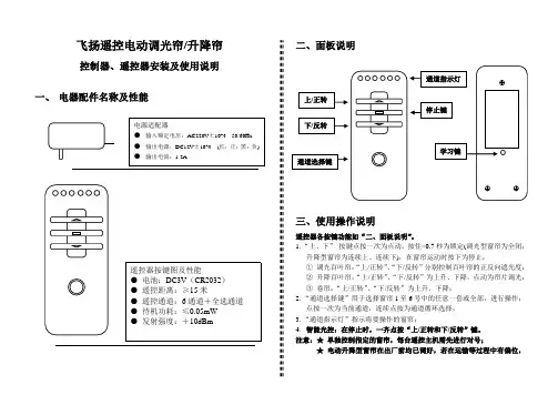
飞扬遥控电动调光帘/升降帘控制器、遥控器安装及使用说明一、 电器配件名称及性能二、面板说明三、使用操作说明遥控器各按键功能如“二、面板说明”。
1.“上、下” 按键点按一次为点动,按住>0.7秒为锁定(调光型窗帘为全闭;升降型窗帘为连续上、连续下),在窗帘运动时按下为停止; ① 调光百叶帘:“上/正转”、“下/反转”分别控制百叶帘的正反向遮光度; ② 升降百叶帘:“上/正转”、“下/反转”为上升、下降,点动为帘片调光; ③ 卷帘:“上/正转”、“下/反转”为上升、下降; 2.“通道选择键”用于选择窗帘1至6号中的任意一套或全部,进行操作;点按一次为当前通道,连续点按为通道循环选择; 3.“通道指示灯”指示将要操作的窗帘;4.智能光控:在停止时,一齐点按“上/正转和下/反转”键。
注意:★ 单独控制指定的窗帘,每台遥控主机需先进行对号;★电动升降型窗帘在出厂前均已调好,若在运输等过程中有偏位,则需重新设置上下行程操作;四、学习操作说明A.通道学习:①、关掉主机电源,8秒后打开主机源;②、在20秒内(不可进行运行操作)按下主机的“学习”键;③、在20秒内(不可进行运行操作)按下遥控器“学习键”,此时窗帘动一下,表示进入学习状态,否则操作失败,从第①步重新操作;④、按动通道选择键到将要学习的通道,然后按“停止键”,窗帘动一下,成功学习此通道,否则再次按“停止键”;⑤、可重复第④步学习多通道或摇控器;⑥、按遥控器“学习键”退出。
B.清除已学习的摇控通道:①、进入学习状态(不做任何操作);②、接着长按遥控器“学习键”,清除成功窗帘动一下,否则操作失败,从第①步重新操作。
C.“锁定”行程学习:①、进入学习状态。
点按通道键到要设置的窗帘通道;②、同时按下摇控器上的“通道选择键和停止键”(可先按住通道选择键然后再按下停止键)窗帘动一下,表示进入学习行程状态,否则再次按下“通道选择键和停止键”;③、上位设置:用上键、下键、停止键将窗帘调至上位合适位置,同时按下遥控器“通道选择键和停止键”确认;④、下位设置:用上键、下键、停止键将窗帘调至下位合适位置,同时按下遥控器“通道选择键和停止键”确认退出。
单极无线数码遥控窗帘使用说明书一、产品概述:随着人们生活水平的不断提高,科学技术的不断进步,遥控窗帘取代传统式开关将成为现代人追逐的潮流。
本公司研制的无线数码遥控窗帘控制器,突破了传统开关方式,并体验了高科技给生活、工作带来的方便和无限乐趣。
二.产品特点:1、采用无线数字识别技术,每个开关各自独立密码,不会相互干扰。
2、兼容常规手动操作功能,无线射频遥控,无方向性,可穿越墙壁。
3、依据国际标准86外型设计。
4、适用电动窗帘控制器,无需另接外围器件。
5、开关与遥控器之间采用智能分键录码技术,且每个开关系统可实现开、关、停及情景功能的设置,可增配多个遥控器或增装多个开关。
6、遥控窗帘内置用户可换保险管,具有短路过载保护功能。
三、主要技术指标:1、工作电压:AC220V±10%50/60Hz。
2、输出电压:AC220V±10%50/60Hz。
3、额定功率:800W。
4、接收频率:303.825MHz(或可选)。
5、遥控距离:室内不小于20米,室外不小于50米。
6、接线方式:单极(即火线和零线)。
7、环境温度:–20℃~+50℃。
四、安装方法:安装前必须先切断电源,按开关上的标签纸所示接线。
并把电线整理好,防止碰线短路造成开关损坏。
五、遥控码录入开关的方法:遥控窗帘出厂时,没有记录任何遥控码,只能手动控制,要进行遥控操作必须按照如下方法录入遥控码:遥控前进停止后退设置1、先用手控将窗帘电机走到中间,再按住墙壁开关前进触摸区直到电机动一次,松手,然后按遥控器上前进键,控制器收到信号后电机亮动一次,说明前进学习成功,按遥控器上的该键只能控制前进和停止。
2、先用手控将窗帘电机走到中间,再按住墙壁开关后退触摸区直到电机动一次,松手,然后按遥控器上后退键,控制器收到信号后电机亮动一次,说明后退学习成功,按遥控器上的该键只能控制后退和停止。
自动前进停止后退设置先用手控将窗帘电机走到起始短,按住墙壁开关后退或前进触摸区放开再迅速按住墙壁开关后退或前进触摸区直到电机动走到头,松手,按一下墙壁开关后退或前进触摸区走到头自动停止。
“迪瑞杯”第五届吉林省大学生机械创新设计大赛“幸福生活——今天和明天”全自动窗帘设计说明书参赛者:QCR WZC ZLG RJX SSD指导教师:ZZY CWL二〇一二年四月前言如今伴随着信息时代的到来,人们的生活水平日益提高,方便、快捷、自动、智能成为时代的主题,在现代家庭生活环境中,居家环境早已不仅仅局限在物理空间上,人们更为关注的是一个安全、方便、舒适的环境,自动化的电子产品自然成为人们追求的目标。
窗是人心灵的眼睛,窗帘则是眼睛上的睫毛,窗帘在防止强光射入,帮助人们合理的安排时间,美化室内环境,保证个人隐私,增强居家环境方面有重要作用。
随着人们生活节奏的加快,窗帘的自动化随之产生。
本产品是在学习机械原理及设计和电工学等知识,通过实践,观察,思考的基础上设计而成的,且人性化的思想理念也体现了科学技术在人们生活中的作用。
通过几个月的努力,使我们深刻感受到了电学,力学,加工工艺,理论知识与实践相结合在机械设计中的重要性。
加强和拓展这些方面的知识对机械学子们是很有必要的。
由于我们能力、经验以及一些方面的知识有限,许多地方未能深入的研究,如有误漏之处,敬请评委老师批评指正。
编者目录薄窗帘一、薄窗帘传动示意图 (1)二、工作原理 (1)三、执行机构选定 (2)四、电动机的选择 (3)五、轴的设计计算 (5)六、轴承的校核 (7)七、轴承端盖与轴承支座 (8)八、螺栓及连接件的选择与校核 (9)九、薄窗帘电路图 (10)十、电学原件引脚的功能及使用方法 (10)十一、程序流程图 (14)十二、ATmega16单片机程序 (14)厚窗帘一、厚窗帘传动示意图 (20)二、工作原理 (21)三、执行机构选定 (21)四、电动机的选择 (23)五、轴承的选择与校核 (25)六、厚窗帘电路图 (26)七、程序流程图 (26)八、电学原件引脚的功能及使用方法 (28)九、AT89C2051程序 (29)主要创新点 (32)推广应用价值 (32)设计小结 (33)参考文献 (34)薄窗帘薄窗帘属于智能窗帘,能够根据光照的强度,调节窗帘的自动升降。
湄洲湾职业技术学院遥控窗帘说明书系别:自动化工程系 年级: 10级 专业:电气自动化技术姓名:小张学号: 1001020230 导师姓名:赵职称: 讲师2013年5月27日目录1.前言 (1)2.系统设计技术参数要求 (2)3.系统设计 (3)3.1 系统设计总体框图 (3)3.2 各模块原理说明 (3)3.3 系统总原理图 (4)3.4 系统印刷电路板的制作图 (4)3.5 系统的操作说明 (4)3.6 系统操作注意事项 (5)参考文献 (6)致谢语 (7)附录 (8)附录1 总原理图 (8)附录2 印刷电路图 (9)附录3 元件清单 (10)附录4.源程序 (11)1.前言随着社会经济的高速增长,人民生活水平的不断提高,人们对家庭生活舒适性的需求越来越强烈,窗帘作为每个家庭的家居必须用品,自然也需要满足人们更舒适性的需求。
窗帘其基本的作用无非是保护业主的个人隐私以及遮阳挡尘等功能,但传统的窗帘您必须手动去拉动,每天早开晚关也是挺麻烦的,特别是别墅或复式房的大窗帘,比较重,而且长,需要很大的力量才能开关窗帘,很不方便;于是遥控电动窗帘在最近几年得到迅速发展,并广泛应用于智能大厦、高级公寓、酒店和别墅等领域,只要遥控器轻按一下,窗帘就自动开合(百叶窗可以自动旋转),非常方便。
在本次设计中,我们主要研究的是利用单片机的无线遥控电路的设计。
2.系统设计技术参数要求1.遥控可以控制窗帘的开和关。
2.当开关状态时有指示灯显示开关状态。
3.有行程开关起到限位作用。
4.有继电器输出,可以控制任何电压的电机负载,实用性强。
3.系统设计3.1 系统设计总体框图3.2 各模块原理说明1.电源模块:给电源提供5v的电源。
2.STC89C52 芯片:STC89C52是整个系统的核心部件,在单芯片上,拥有灵巧的8 位CPU 和在系统可编程Flash,其中内部由CPU来运行、控制。
有四个并行I\O口(32 位),分别是P0、P1、P2和P3,POM用来存放程序,通过RAM来存放中间结果。
电动窗帘使用说明书使用说明书尊敬的用户:感谢您购买我们的电动窗帘产品。
为了让您更好地了解和使用这款产品,我们特别为您准备了以下使用说明。
在使用之前,请先认真阅读本说明书,以确保您正确而安全地操作和享受我们的产品。
一、产品概述电动窗帘是一款便捷、智能的窗帘控制设备。
通过内置的电动机和遥控器,您可以轻松实现窗帘的开闭、停止和定时控制功能。
本产品采用了先进的无线通信技术和电机控制技术,具有操作简单、安全可靠等特点,适用于家庭、办公室、酒店等各种场所。
二、安装步骤1. 打开包装,取出电动窗帘主体和遥控器。
2. 找到适合安装的位置,用螺丝固定电动窗帘主体于窗帘轨道上。
确保安装牢固。
3. 将窗帘卷入窗帘轨道,并将窗帘绳穿过主体上的字母标记孔。
4. 使用遥控器添加设备并设置连接。
详细操作方法请参考遥控器说明书。
5. 安装完成后,检查窗帘是否畅顺移动,确保安装无误。
三、基本操作1. 开启窗帘按遥控器上的“开”键,窗帘将自动向上升起,开启窗户。
可以根据需要按住该键,窗帘会自动停止升起。
2. 关闭窗帘按遥控器上的“关”键,窗帘将自动向下关闭,覆盖窗户。
同样可以按住该键,窗帘会自动停止关闭。
3. 窗帘暂停在窗帘运动过程中,按下遥控器上的“停”键,窗帘会立即停止运动。
4. 定时功能本产品还支持定时功能,您可以在遥控器上设置定时开启或关闭窗帘的时间,实现自动控制。
四、注意事项1. 请勿将手指或其他物体放入窗帘轨道,以免造成伤害。
2. 请勿使用湿手操作遥控器,避免触电的危险。
3. 本产品只适用于干燥的室内环境,请避免使用在潮湿或有水汽的地方。
4. 当窗帘卷严重不平整或运动不畅时,请及时检查和维修。
5. 请勿私自拆解、修理本产品,如需维修,请联系专业人员或售后服务。
五、售后服务对于我们的产品,我们提供一年的质保期,质保期内如有质量问题,我们将提供维修和更换服务。
如需售后服务,请拨打我们的服务热线或发送邮件至我们的售后邮箱。
六、结束语谢谢您的选择和信任,我们将始终致力于为您提供优质的产品和满意的服务。
窗帘遥控器使用说明书欢迎使用窗帘遥控器!本说明书将为您详细介绍该遥控器的功能和使用方法,以便您能够轻松便捷地控制窗帘的开闭和调节。
在开始使用前,请确保已经正确安装窗帘遥控器并已连接电源。
一、功能介绍窗帘遥控器具备以下主要功能:1. 开关功能:通过遥控器上的开关按钮,您可以控制窗帘的开启和关闭。
2. 位置调节:使用遥控器上的调节按钮,您可以将窗帘定位到所需的位置,以便对光线的控制和私密性的保护。
3. 多组窗帘控制:该遥控器支持同时控制多组窗帘,方便您一键操作多个窗帘。
二、使用方法1. 开关窗帘:按遥控器上的开关按钮,可以实现窗帘的开启和关闭功能。
一次按下按钮,窗帘会从当前位置启动至完全打开或关闭。
如需过程中停止窗帘的开闭,请再次按下开关按钮即可。
2. 位置调节:使用遥控器上的调节按钮,您可以将窗帘定位到所需的位置。
按住“上升”按钮,窗帘将缓慢上升,松开按钮后窗帘将停止在当前位置。
同样地,按住“下降”按钮,窗帘将缓慢下降,松开按钮后窗帘停止在当前位置。
如需微调位置,请短按调节按钮,窗帘将以较小步长上升或下降。
3. 多组窗帘控制:若您的房间有多组窗帘需要控制,在遥控器上会有对应的编号按钮,编号从1开始递增。
按下对应编号按钮即可实现控制对应窗帘的功能。
三、注意事项1. 请将遥控器放置在易于触及的位置,避免摔落或遗失。
2. 遥控器内部配备了电池,请定期检查电池电量,并及时更换。
电池更换时,请确保使用与原电池相同型号以及正确安装极性。
四、故障排除1. 若遥控器操作无响应,请检查电池电量是否耗尽,如是,请更换新电池。
2. 若无法控制窗帘位置,请确保窗帘电源已连接,并且电机正常工作。
如有异常,请联系售后服务人员进行维修。
请按照上述使用说明正确使用窗帘遥控器。
如有其他问题或需要进一步的帮助,请联系我们的客户服务热线,我们将竭诚为您解答。
谢谢!。
“迪瑞杯”第五届吉林省大学生机械创新设计大赛“幸福生活——今天和明天”全自动窗帘设计说明书参赛者:QCR WZC ZLG RJX SSD指导教师: ZZY CWL二〇一二年四月前言如今伴随着信息时代的到来,人们的生活水平日益提高,方便、快捷、自动、智能成为时代的主题,在现代家庭生活环境中,居家环境早已不仅仅局限在物理空间上,人们更为关注的是一个安全、方便、舒适的环境,自动化的电子产品自然成为人们追求的目标。
窗是人心灵的眼睛,窗帘则是眼睛上的睫毛,窗帘在防止强光射入,帮助人们合理的安排时间,美化室内环境,保证个人隐私,增强居家环境方面有重要作用。
随着人们生活节奏的加快,窗帘的自动化随之产生。
本产品是在学习机械原理及设计和电工学等知识,通过实践,观察,思考的基础上设计而成的,且人性化的思想理念也体现了科学技术在人们生活中的作用。
通过几个月的努力,使我们深刻感受到了电学,力学,加工工艺,理论知识与实践相结合在机械设计中的重要性。
加强和拓展这些方面的知识对机械学子们是很有必要的。
由于我们能力、经验以及一些方面的知识有限,许多地方未能深入的研究,如有误漏之处,敬请评委老师批评指正。
编者目录薄窗帘一、薄窗帘传动示意图 (1)二、工作原理 (1)三、执行机构选定 (2)四、电动机的选择 (3)五、轴的设计计算 (5)六、轴承的校核..................................................................................... . (7)七、轴承端盖与轴承支座 (8)八、螺栓及连接件的选择与校核 (9)九、薄窗帘电路图 (10)十、电学原件引脚的功能及使用方法 (10)十一、程序流程图 (14)十二、ATmega16单片机程序 (14)厚窗帘一、厚窗帘传动示意图 (2)二、工作原理 (21)三、执行机构选定 (21)四、电动机的选择………………………………………………………………….……… (23)五、轴承的选择与校核 (2)5六、厚窗帘电路图 (26)七、程序流程图 (26)八、电学原件引脚的功能及使用方法 (28)九、AT89C2051程序 (29)主要创新点 (32)推广应用价值 (32)设计小结………………………………………………………………………… (33)参考文献 (34)薄窗帘薄窗帘属于智能窗帘,能够根据光照的强度,调节窗帘的自动升降。
电动窗帘遥控操作说明随着科技的不断发展,电动窗帘逐渐走进了我们的生活,为我们带来了更加便捷和舒适的体验。
电动窗帘的遥控操作简单易懂,下面就为您详细介绍一下。
一、遥控器按键功能我们先来看一下遥控器上的各个按键及其功能。
1、“开”键:按下此键,电动窗帘会自动打开,直至完全展开。
2、“关”键:当您按下这个按键时,电动窗帘会缓缓关闭,直到完全闭合。
3、“暂停”键:在窗帘打开或关闭的过程中,如果您想要暂时停止窗帘的动作,就可以按下“暂停”键。
再次按下“开”或“关”键,窗帘会继续之前的动作。
4、“调速”键:部分遥控器上会设有调速按键,您可以通过它来调整窗帘打开或关闭的速度,一般分为快速、中速和慢速三个档位,以满足您不同的需求。
二、遥控器使用前的准备在开始使用遥控器操作电动窗帘之前,您需要做一些准备工作。
1、安装电池:首先,打开遥控器的电池仓盖,按照正负极的指示正确安装电池。
通常使用的是普通的干电池,如五号或七号电池。
2、对码:新安装的电动窗帘或者更换电池后,可能需要进行遥控器与窗帘电机的对码操作。
对码的方法因品牌和型号而异,但一般来说,您需要同时按下遥控器上的特定按键(如“开”和“关”键)和电机上的对码按钮,直到电机发出“嘀”的一声,表示对码成功。
三、日常操作步骤接下来,让我们一起了解一下电动窗帘的日常操作步骤。
1、打开窗帘:当您想要打开窗帘时,只需轻轻按下遥控器上的“开”键。
窗帘会按照您预先设定的速度平稳地展开。
在窗帘打开的过程中,如果您觉得阳光太强或者想要改变窗帘的打开程度,可以按下“暂停”键,然后根据需要再次按下“开”键继续打开,或者按下“关”键调整窗帘的位置。
2、关闭窗帘:当夜幕降临或者您需要隐私空间时,按下遥控器上的“关”键,电动窗帘会自动闭合。
同样,如果在关闭过程中您想要停止或者调整窗帘的位置,使用“暂停”键即可。
3、调整窗帘位置:如果您只是想微调窗帘的位置,比如让窗帘打开一半或者只关闭一部分,可以在窗帘运动过程中适时按下“暂停”键,以达到您满意的效果。
Zigbee Blinds Actuator MiniArt. no.: 57008000Operating instructions1Safety instructionsTo avoid possible damage, read and follow the following instructions:Installation only by persons with appropriate knowledge and experience in the followingareas:– 5 safety regulations and standards for the installation of electrical systems–Selection of suitable tools, measuring devices, installation materials and, if necessary, personal protective equipment–Installation of the installation material–Connection of devices to the building installation under consideration of local connection conditionsImproper installation endangers your own life and the lives of users of the electrical system and there is a risk of serious damage to property, e.g. through fire. You are at risk of personal liabil-ity for personal injury and damage to property.Contact an electrical contractor!Risk of injury. Use the device only for controlling Venetian blind and roller shutter motors or awnings. Do not use it to switch other loads.For parallel connection of several motors to an output it is essential to observe the correspond-ing instructions of the manufacturers, and to use a cut-off relay if necessary. The motors may be destroyed.Use only venetian blind motors with mechanical or electronic limit switches. Check the limit switches for correct adjustment. Observe the specifications of the motor manufacturers. Device can be damaged.Read the instructions in full, observe them and keep them for future reference.2Device componentsFigure 1(1)Venetian blind actuator(2)Button Prog.(3)LED(4)Terminals3Intended use–Zigbee actuator for controlling electrically driven Venetian blinds, shutters and awnings–Zigbee transmitter to operate Zigbee-compliant Venetian blind drives–Operation of Zigbee-compliant transmitters or connected Venetian blind push-buttons–Mounting in appliance box according to DIN 49073 with a suitable cover4Product characteristics–Zigbee Certified Product–Positioning of the blind/shutter and slat–Switchable output with Prog. button–Blind/shutter running time and slat change-over time can be saved–Input to connect a Venetian blind push-button–Parameterising via app–Updating via app5OperationOperation with connected Venetian blind push-buttonMoving the blind/shutter■Press top or bottom button for longer than one second.The blind/shutter moves in the desired direction to the end position or stops when the but-ton is pressed again.Adjusting the slats■Press top or bottom button for less than 1 second.Transmitter functionAdditional Zigbee devices for controlling blinds/shutters can be connected to the actuator. This function is set with the NEXENTRO Config app. The devices are then operated in the same way as the actuator when a push-button is pressed.Radio operationThe operation is done with Zigbee transmitters or Zigbee gateways that comply with Zigbee Standard 3.0. The scope of functions and the type of operation depends on the transmitter or gateway used.6Fitting and electrical connectionTo ensure good transmission quality, keep a sufficient distance from any possible sources of in-terference, e.g. metallic surfaces, baby monitors, microwave ovens, WiFi routers and wireless headphones.DANGER!Electrical shock when live parts are touched.Electrical shocks can be fatal.Before carrying out work on the device or load, disengage all the corresponding cir-cuit breakers, secure against being switched on again and check that there is novoltage!Recommendation: Use an appliance box with an installation depth of 60 mm.Figure 2: Connection diagram(5)Venetian blind push-buttonFigure 3: Clampable conductor cross-section■Make the connection according to the connection diagram (Figure 2). In doing so, note the clampable conductor cross-section (Figure 3).■Insert the actuator in the appliance box in such a way that the Prog. button and status LED are visible.The load can be switched by briefly pressing the Prog. button.Press the Prog button for less than 1 second: Blind moves in the bottom end position dir-ection.Press the Prog button for longer than 1 second: Blind moves in the upper end position dir-ection.■Mount a suitable cover or Venetian blind push-button.■Perform commissioning.7Commissioning with appThe requirement for commissioning via app is a mobile end device (smartphone, tablet) with Bluetooth interface, running the Android or iOS operating system. The app guides you step by step through the commissioning process.Prerequisite for scenes and positioning movements is that the moving times of the con-nected blind/shutter in the actuator are saved.■Download and install the NEXENTRO Config app from the iTunes App Store (iOS) or Google Play Store (Android).App functions–Joining an existing network–Setting up your own network–Assigning device names–Setting device parameters: Blind/shutter running time, slat adjusting time, pause time for direction change–Reverse function of inputs and outputs–Connecting the actuator with Zigbee transmitters, actuators or gateways–Indication of the position and of the slat angle–Indication of device information: Device type, software version–Performing a software update–Resetting to default setting–Operating the actuator for test purposesRegistering new devices in the NEXENTRO Config appNEXENTRO devices must be registered for commissioning in the NEXENTRO Config App. To do this, the new unit must be put into pairing mode, which is active for approx. 1 minute after mains voltage recovery.■Re-energise the NEXENTRO device and start the search in the NEXENTRO Config App.■Add the new device to the list of registered devices.■Assigning device names (optional).With a registered device, connecting to a terminal is possible at any time.Adding the NEXENTRO actuator to a Zigbee network with gatewayTo connect the NEXENTRO actuator to other Zigbee devices, the NEXENTRO actuator must be added to the network.With certain gateways, adding to a network is done via the Touchlink function, see http://www.nexentro.de/help.■Start the search mode for new devices in the app of the gateway to open the network for further Zigbee devices. The function call depends on the gateway, e.g. "Search devices".■Select function Join Network in the NEXENTRO Config App.The actuator joins the Zigbee network and is displayed in the app of the gateway.The NEXENTRO Config App shows all available devices that can be controlled via thesensor function of the actuator.■Select the devices.Create a Zigbee network with the NEXENTRO actuator (without gateway)A Zigbee network can be created with a NEXENTRO actuator and other NEXENTRO devices can be added to the network. Adding additional Zigbee devices is always done via the NEXEN-TRO device with which the Zigbee network was created.■Select function Create Network in the NEXENTRO Config App.■For NEXENTRO devices to join the network, select Join Network.The NEXENTRO actuator has created a Zigbee network. The device search starts and searches for devices to join the network.All available Zigbee devices are shown.■Select the devices.Adding the NEXENTRO actuator to a Zigbee network of NEXENTRO devicesThe NEXENTRO actuator can be added to a network created with another NEXENTRO device via the function Create Network.■Carry out the device search in the NEXENTRO Config App for the NEXENTRO device with which the Zigbee network was created.■Switch to the NEXENTRO actuator to be added to the Zigbee network.■Select the Join Network function.The actuator joins the Zigbee network.All available devices that can be controlled via the sensor function of the actuator areshown.■Select the devices.Joining a Zigbee network with a NEXENTRO actuator via TouchlinkRequirement: The distance between the Zigbee transmitter and the NEXENTRO actuator is 10 to 20 cm.■Select function Touchlink in the NEXENTRO Config App.The NEXENTRO actuator is ready to join the Zigbee network.■Trigger Touchlink on the Zigbee transmitter.The actuator joins the Zigbee network and is connected to the transmitter.The NEXENTRO Config App shows all available devices that can be controlled via the sensor function of the actuator.■Select the devices.8Commissioning without appA simplified commissioning can also be carried out without the app.Prerequisite: The actuator is in the default setting or the assignment to a Zigbee network has been deleted.■Open the network of the gateway, see gateway app.■Switch on mains voltage.The actuator searches for the gateway's Zigbee network for 1 minute.The blind/shutter is activated briefly in both running directions, the actuator has found the network and joined it. The actuator is displayed in the app of the gateway.■If the actuator is operated without a gateway, connect the actuator to a transmitter via Touchlink within 5 minutes after switching on the mains voltage.A more detailed configuration can only be carried out with the NEXENTRO Config App.DANGER!Mortal danger of electric shock.The following work must be carried out under mains voltage and therefore may onlybe carried out by an electrician!Only use insulated tools for the work! Cover up live parts in the working environ-ment.Saving blind/shutter running timePrerequisite for scenes and positioning movements is that the moving times of the con-nected blind/shutter in the actuator are saved.■Press the Prog. button for longer than 1 second; release the button when the blind/shutter starts moving.Blind/shutter moves in the upper end position direction.■As soon as the upper end position is reached, press the Prog. button for longer than4 seconds; release the button when the blind/shutter starts moving.The blind/shutter moves in the bottom end position direction. The LED flashes green.■When the bottom end position is reached, press the Prog. button again.The LED flashes red.■With shutters: Press the Prog. button for less than 1 second.The running time is saved and the blind/shutter moves to the upper end position.■With Venetian blinds: Press the Prog button for longer than 1 second and keep it pressed until the slats have been fully changed over, then release the button.The running time and change-over time is saved and the blind/shutter moves to the upper end position.9Reset deviceDeleting assignment to a Zigbee network■Switch off the supply supply to the device three times in quick succession and switch it on again. The pause between switching operations must be less than two seconds.The actuator confirms the deletion of the network assignment by briefly activating theblind/shutter in both running directions.Resetting the device to the factory settingThe device deletes the assignment to a network, all connections to Zigbee devices and the parameters saved on the device. Alternatively, the device can also be reset with the NEXEN-TRO Config app.DANGER!Mortal danger of electric shock.The following work must be carried out under mains voltage and therefore may onlybe carried out by an electrician!Only use insulated tools for the work! Cover up live parts in the working environ-ment.Precondition: Load is switched off.■Press the Prog button (2) for longer than 20 seconds.The blind/shutter moves in the upper end position direction.After approx. 20 seconds, the LED flashes rapidly alternately red and green.■Within 10 seconds, release the button and press it again briefly.The LED flashes more slowly alternately red and green, the device is reset to the default settings and is restarted.After resetting the device to the default setting, the device has to be removed from theNEXENTRO Config App. For iOS devices, the device also has to be removed from the list of paired Bluetooth devices (Settings/Bluetooth). Otherwise, re-pairing will not be pos-sible.10Technical dataRated voltage AC 230 / 240 V ~ Mains frequency50 / 60 Hz Standby power max. 0.2 W Running time 1 ... 120 s Ambient temperature-5 ... +45 °C Storage/transport temperature-25 ... +70 °C Dimensions L×W×H approx. 48 x 51 x 20 mmConnected loadMotors700 WCommunication protocol Zigbee 3.0 (router) Radio frequency 2.400 ... 2,483 GHz Transmission capacity 1 mW BluetoothRadio frequency 2.402 ... 2.480 GHz Transmission capacity max. 2.5 mW, Class 2 Transmitting range typ. 10 m 11Declaration of conformityInsta GmbH hereby declares that the radio system type art. no. 57008000 meets the directive 2014/53/EU. You can find the full article number on the device. The complete text of the EU De-claration of Conformity is available under the Internet address:www.insta.de/instastorefront/services/downloads12WarrantyWe reserve the right to make technical and formal changes to the product in the interest of tech-nical progress.We provide a warranty as provided for by law.Please send the unit postage-free with a description of the defect to our central customer ser-vice office:Insta GmbHService CenterHohe Steinert 1058509 LüdenscheidGermanyInsta GmbHPostfach 183058468 LüdenscheidGermanyTelefon +49 (0) 2351 936-0www.insta.de*************。
电动窗帘遥控器说明书电动窗帘遥控器使用说明书一、产品概述该电动窗帘遥控器是一种用于控制电动窗帘开闭的便携式遥控设备,通过无线方式与电动窗帘进行通信,并实现对窗帘的远程控制。
本说明书将详细介绍该遥控器的功能、使用方法以及注意事项,帮助用户正确、便捷地操作和使用该产品。
二、产品外观1. 遥控器主体:遥控器主体采用人性化设计,外形简洁,手感舒适。
主体上配有一块液晶屏幕和若干个功能按键。
2. 液晶屏幕:液晶屏幕用于显示窗帘的状态、传输信息等。
屏幕上方有一个电池电量指示图标,用于显示遥控器电池的剩余电量。
3. 功能按键:遥控器上配有一系列功能按键,包括开启、关闭、停止、上升、下降等。
按键通过软触摸设计,操作灵敏,按下即可触发相应功能。
三、产品功能与使用方法1. 开启窗帘:按下“开启”按键,即可发出开启窗帘的指令,窗帘开始向上升起。
2. 关闭窗帘:按下“关闭”按键,即可发出关闭窗帘的指令,窗帘开始向下降落。
3. 停止窗帘:按下“停止”按键,即可发出停止窗帘的指令,窗帘立即停止运动。
4. 上升窗帘:按下“上升”按键,即可发出窗帘上升的指令,窗帘开始向上升起。
5. 下降窗帘:按下“下降”按键,即可发出窗帘下降的指令,窗帘开始向下降落。
6. 调节窗帘:遥控器上还配有“+”和“-”两个调节按键,用于控制窗帘的开合程度。
按下“+”键,窗帘会向上升起更多;按下“-”键,窗帘会向下降落更多。
7. 设置定时:通过遥控器的设置功能,您可以对窗帘进行定时开启、关闭的设置。
具体设置方法,请参阅第五部分“设置定时”。
8. 传输距离:遥控器与电动窗帘之间的最大传输距离为30米。
如果遥控器与窗帘超过此距离,遥控器将无法控制窗帘。
四、强调事项1. 电池更换:当遥控器电池电量过低时,液晶屏幕上的电池电量指示图标将转为红色。
此时,请及时更换电池,以免影响正常使用。
2. 避免受潮:遥控器主体不防水,请勿让遥控器受潮,以免造成损坏。
3. 避免摔落:遥控器主体为精密设备,请勿将遥控器摔落或敲击,以免导致损坏。
湄洲湾职业技术学院遥控窗帘说明书系别:自动化工程系 年级: 10级 专业:电气自动化技术姓名:小张学号: 1001020230 导师姓名:赵职称: 讲师2013年5月27日目录1.前言 (1)2.系统设计技术参数要求 (2)3.系统设计 (3)3.1 系统设计总体框图 (3)3.2 各模块原理说明 (3)3.3 系统总原理图 (4)3.4 系统印刷电路板的制作图 (4)3.5 系统的操作说明 (4)3.6 系统操作注意事项 (5)参考文献 (6)致谢语 (7)附录 (8)附录1 总原理图 (8)附录2 印刷电路图 (9)附录3 元件清单 (10)附录4.源程序 (11)1.前言随着社会经济的高速增长,人民生活水平的不断提高,人们对家庭生活舒适性的需求越来越强烈,窗帘作为每个家庭的家居必须用品,自然也需要满足人们更舒适性的需求。
窗帘其基本的作用无非是保护业主的个人隐私以及遮阳挡尘等功能,但传统的窗帘您必须手动去拉动,每天早开晚关也是挺麻烦的,特别是别墅或复式房的大窗帘,比较重,而且长,需要很大的力量才能开关窗帘,很不方便;于是遥控电动窗帘在最近几年得到迅速发展,并广泛应用于智能大厦、高级公寓、酒店和别墅等领域,只要遥控器轻按一下,窗帘就自动开合(百叶窗可以自动旋转),非常方便。
在本次设计中,我们主要研究的是利用单片机的无线遥控电路的设计。
2.系统设计技术参数要求1.遥控可以控制窗帘的开和关。
2.当开关状态时有指示灯显示开关状态。
3.有行程开关起到限位作用。
4.有继电器输出,可以控制任何电压的电机负载,实用性强。
3.系统设计3.1 系统设计总体框图3.2 各模块原理说明1.电源模块:给电源提供5v的电源。
2.STC89C52 芯片:STC89C52是整个系统的核心部件,在单芯片上,拥有灵巧的8 位CPU 和在系统可编程Flash,其中内部由CPU来运行、控制。
有四个并行I\O口(32 位),分别是P0、P1、P2和P3,POM用来存放程序,通过RAM来存放中间结果。
本设计其主要管脚连接分别为:VCC供5V电压,GND接地,P0口(P0.1~P0.7)连接电机驱动模块最后连接无线模块P1口(P1.0~P0.4)连接按键模块实施对显示模块的控制,芯片XTAL1脚与XTAL2连接晶振模块,RST脚则为复位输入。
采用8位的STC89C52单片机做控制器,程序采用C语言编程。
利用直流电机正反转,实现控制窗帘的开关。
3.晶振模块:用于产生震荡电流,为单片机工作时所需要的内部时钟信号,便于各部分保持同步。
在芯片的外部通过XTAL1输入和XTAL2的输出,电路上并联一个晶体振荡器和两个瓷片电容,形成反馈电路,构成一个稳定的自激振荡器。
本设计电路内的C2、C3电容大小为20pf和一个12MHZ的晶体振荡器组成4.无线模块: 无线遥控是由SC2262/SC2272 编码解码芯片组成的无线发送接收模块,通过SC2272接收输出端D0、D1、D2、D3输出信号控制单片机,再利用单片机控制L298N来控制直流电机。
利用霍尔传感器来实现窗帘的防过卷。
5.复位电路:采用上电自动复位和手动按键复位两种方式实现系统的复位操作。
上电复位要求接通电源后,自动实现复位操作。
手动复位要求在电源接通的条件下,在单片机运行期间,用按钮开关操作使单片机复位。
上电自动复位通过电容C3充电来实现。
手动按键复位是通过按键将电阻R1与VCC接通来实现。
6.按键模块:本设计有3个按键分别是遥控器上的按键1,按键2分别控制电机转向,也就是窗帘移动方向,按键3为主电路上的复位键用于手动复位。
7.状态显示模块:本功能采用在直流电动机两侧并接发管二极管实现,正转是绿灯亮,反转时红灯亮。
3.3 系统总原理说明设计是基于STC89C52单片机的遥控窗帘。
它采用无线遥控控制方式,其中SC2262/SC2272 编码解码芯片组成无线发送接收模块;通过控制直流电机的正反转来控制窗帘的开关,并且可以指示运行状态;利用限位开关来控制窗帘停止,防止过卷。
本系统采用C语言编程,主要使用了if、while等判断语句,按键采用高电平有效模式。
当有按键按下时,无线发射模块发出信号,接收模块解码后响应相应功能,当限位开关闭合时,说明窗帘已经到达指定位置,停止转动。
3.4 系统印刷电路板的制作图系统印刷电路板的制作图详见附录33.5 系统的操作说明1.当发射电路(遥控器)下降键(红)按一下,此时电机正传,同时红灯亮。
2.中途再按一下下降键,此时电机停转,红灯灭。
3.当下降到最底部,即碰上行程开关(红),此时电机停转。
4.当发射电路(遥控器)上升键(绿)按一下,此时电机反传,同时绿灯亮。
5.中途再按一下上升键,此时电机停转,绿灯灭。
6.当上升到最顶部,即碰上行程开关(绿),此时电机停转。
3.6 系统操作注意事项1.通电使用前先对照电路板与电路图是否有错焊、漏焊、短路、开路、元器件相碰等现象,有要处理好后再使用。
2.通电使用前先检查好电路板是否与电源供电线、驱动电路开关与负载供电线、负载供电线之间相互接反,不得在接错的情况下通电,要处理好后再使用。
3.应把电极片与电路板隔离,避免电极片与电路板上元器件相碰触发生短路现象。
4.通电时应把电路板放在绝缘物体上,避开其他导电物体避免发生短路现象。
5.使用时闻到烧焦味、发现元器件或集成块冒烟烧毁应立即断开电源,待电路板查明原因处理好后才可以继续通电使用。
6.调试电路时应小心操作,避免万用表笔或其它导电工具造成人为短路。
7.通电时电源不能太大,以免烧坏芯片。
系统设计参考文献[1]余发山,王福忠.单片机原理及应用技术[M].北京:中国矿业大学出版社.2008.6.[2]康华光.电子技术基础(数字部分)[M],北京:高等教育出版社.2008.5.[3]李朝青.单片机原理及接口技术[M].北京:北京航天航空大学出版色,2001.6.[4]胡汉才.单片机原理及其接口技术[M].北京:清华大学出版社,2004.3.[5]邹书文,黄光桂.无线电遥控单片机[J].电脑与信息技术.1995.10.[6]李光飞,楼然苗,胡佳文等.单片机课程设计实例指导[M].北京:北京航空航天大学出版社.2004.12.首先感谢我们的指导老师赵立琼,她严谨细致、一丝不苟的作风一直是我工作、学习中的榜样;她循循善诱的教导和不拘一格的思路给予我们无尽的启迪。
在此特向赵老师致以诚挚的谢意和崇高的敬意!此外还要感谢所有的电子系的课任老师和帮助过我的的同学们。
在学习中,老师严谨的治学态度、丰富渊博的知识、敏锐的学术思维、精益求精的工作态度以及侮人不倦的师者风范是我终生学习的楷模,导师们的高深精湛的造诣与严谨求实的治学精神,将永远激励着我。
这三年中还得到众多老师的关心支持和帮助。
在此,谨向老师们致以衷心的感谢和崇高的敬意!!!如果说赵老师在专业知识上给予我极大的帮助和激励的话,那么在我的幕后默默的支持我,鼓励我的父母也是使我能准时且成功的完成这次毕业设计的全过程的不可缺少的一部分。
他们虽然不懂专业知识,无法帮我解决在电路设计和程序编程过程中所遇到的困难,但是他们在我做论文时不怕辛苦为我准备好了一切,使我能够无后顾之忧的去做论文。
我相信我父母的辛苦不会白费的,我成功了。
这不只是我一个人的成功,是我的老师,我的父母共同努力而取得的成就!此外,我还要感谢在一起度过愉快的大学生活的全班同学,正是由于你们的帮助和支持,我才能克服一个又一个的困难和疑惑,直至本次毕业设计的顺利完成,在编写程序的过程中,我想特别感谢我的一位同学正因为有他的不怕厌倦的帮助和对我的一次又一次的鼓励我才能成功的完成本次的设计,在硬件调试时,我同时也感谢和我一起调试的叶青同学,他给予了我很大的帮助。
谢谢大家!附录1 总原理图附录2 印刷电路图附录3 元件清单附录4 源程序#include<reg52.h>#include<intrins.h>#include<absacc.h> //头文件#define uc unsigned char#define ui unsigned intsbit in_go = P1^1; //窗帘遥控开sbit in_back = P1^2; //窗帘遥控关sbit out_go = P3^5; //继电器驱动电机正转(开)sbit out_back = P3^0; //继电器驱动电机反转(关)sbit limit_go = P3^4; //开到最大位置的行程开关sbit limit_back = P3^6; //关到最大位置的行程开关sbit led_go = P1^5; //开窗帘的指示灯sbit led_back = P1^7; //关窗帘的指示灯void main() //主函数{led_go=0; //灭红灯led_back=0; //灭绿灯while(1) //主循环{if((in_go==0)&&(in_back==1))//判断开关{if(limit_go==1) //再判断行程开关{out_go=~out_go;//取反led_go=~out_go;//取反}while(!in_go);}else if((in_back==0)&&(in_go==1))//如不符合判断这个{if(limit_back==1){out_back=~out_back;led_back=~out_back;}while(!in_back);}if((limit_go==0)&&(limit_back==1))//判断行程开关{out_go=1;led_go=0;}else if((limit_go==1)&&(limit_back==0))//如不符合判断这个{out_back=1;led_back=0;}}}。