时间控制器说明书
- 格式:doc
- 大小:805.00 KB
- 文档页数:2
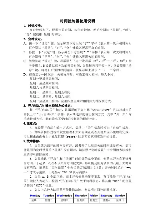
时间控制器使用说明1.时钟校准:在时钟状态下。
根据当前时间,按住时钟键。
然后分别按“星期”、“时”、“分”键校准星期时和分。
2.定时设定:A.按一下“设定”键,显示屏左下方出现“1ON”字样(表示第一次开机时间),再分别按“星期”、“时”、“分”键输入所需开启的时间。
B.再按一下“设定”键,显示屏左下方出现“1OFF”字样(表示第一次关机时间),再分别按“星期”、“时”、“分”键输入所需关闭的时间。
C.继续按动“设定”键,显示屏左下方一次显示(2ON 、2OFF。
10ON 、10OFF)参考步骤A、B设置以后各次的开关时间,如果每天只开关一次,则必须按“清除”键,将他们后面的时间清除,使显示屏上显示“--:--”字样。
D.在设定1—10次开、关机程序时,可设定每天相同,每天不同:星期一至星期五相同,星期一至星期六相同,星期六与星期日相同。
星期一、星期三、星期五相同,星期二、星期四、星期六相同,星期一至星期三相同,星期四至星期六相同共九种控制方式。
3.开/自动/关输出控制方式设定:按“开/自动/关”键时,显示屏的下方出现“ON/AUTO/OFF”且与相对应的面板上有“开/自动/关”字样,表示所选择的输出控制方式。
其中“开、关”为手动控制方式,此时输出不受时间控制器的程序控制。
4.注意点:A.在设置“自动”输出方式时,必须由“关”状态转换为“自动”状态。
B.如果在操作过程中发生错误不知如何纠正或者其他原因不能顺利完成,可以按正面面板上小孔复位键(reset)回到初始状态重新开始设置。
5.故障排除:A.如果某天该开的时间没有开,或者开了以后到关的时间还没有关,那可能是因为定时设置的“星期”没有调对,请按照“定时设置”中介绍的方法检测重调即可排除故障。
B.如果确认“开启”和“关闭”时间调的完全正确。
但是本开关在不该开的时间开了起来,或者不该关的时间被关掉,那可能是因为多余的几组开关时间没有清除,请参照“定时设置”中介绍的方法清除(注意:开关时间显示“--:--”才表示清除,不是显示“00:00表示清除)C.如果A、B全部正确,而本开关依然动作不正常,有可能是“开/自动/关”键被人为动作,检测“开/自动/关”处于何种状态,将其由“OFF”的位置调整到“AUTO”位置。

8300系列控制器使用说明书8374,8376,8379,8382型8354,8356,8359,8362型2非常感谢您选择使用尼尔森EZ Pro ™Jr.8300控制器。
EZ Pro ™Jr.8300控制器系列采用了目前最先进的电子技术,将会为您提供更加长期可靠的服务。
请仔细阅读下面的相关产品介绍,以便您能掌握EZ Pro ™Jr.8300控制器程序的编写,操作,安装以及一些相关的注意事项。
一.特点:•尼尔森独特的选择&调节编程系统•不需要交流电源或干电池,编好的程序的保存由锂电池来提供能源,程序稳定•对任何一站都可以有不同的延迟时间•三个独立的程序•每个程序有三个开始时间(一共九个)•开始时间重叠•三个灌溉日历,满足不同的需求(周制,月制,单双日)•程序有重要日设置•预留雨量传感器接口•万年历•水预算选择,减少或增加灌溉水量的1~200%•可设定每月或每年的灌水量•两个测试循环(手动测试和循环测试)•灌水时间从1分钟到1小时59分钟•聚乙烯保险保护电路安全二.安装说明EZ Pro ™Jr.8300控制器既可安装在室内,也可安装在室3外。
电源为220V 。
将EZ Pro ™Jr.8300控制器安装在与人眼睛水平的位置。
用螺丝钉将其固定在墙上。
电源配线220V 交流电源警告:连接变压器之前不要接通220V 交流电源.安装完所有的设备之后再将变压器连接到电源上.这样能防止短路事故,以免损坏控制器.电源电缆和信号电缆用普通的电缆就可以了,连接控制器和执行器的低压信号和电源电缆应当有保护措施。
拧下两个螺丝,取下变压器保护盖,将电线通过盒底的孔,连接到内置变压器的接口上(在野外,电线的绝缘温度应达到75度,并由绝缘管保护).。
安装说明适应型号8374,8376,8379,8382(见右图)拧下变压器保护盖上的两个螺丝,并取下保护盖。
将220V 交流电源连接到变压器上,同时确保黄绿相间的地线已接好。
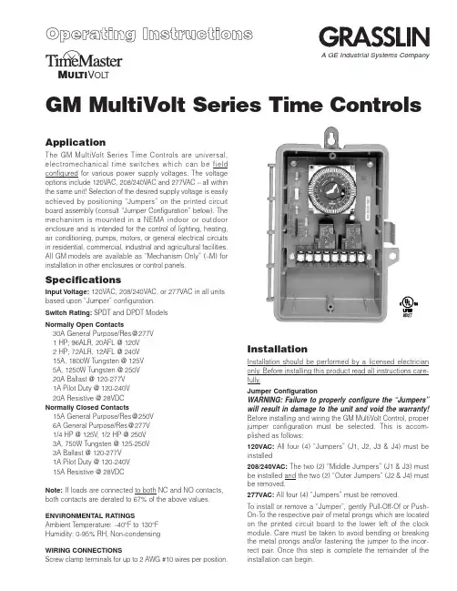
GM MultiVolt Series Time ControlsM UL TI V OL TApplicationThe G M MultiVolt Series Time Controls are universal,electromechanical time switches which can be field configured for various power supply voltages. The voltage options include 120VAC, 208/240VAC and 277VAC – all within the same unit! Selection of the desired supply voltage is easily achieved by positioning “Jumpers” on the printed circuit board assembly (consult “Jumper Configuration” below). The mechanism is mounted in a NEMA indoor or outdoor enclosure and is intended for the control of lighting, heating,air conditioning, pumps, motors, or general electrical circuits in residential, commercial, industrial and agricultural facilities.All G M models are available as “Mechanism Only” (–M) for installation in other enclosures or control panels.SpecificationsInput Voltage:120VAC, 208/240VAC, or 277VAC in all units based upon “Jumper” configuration.Switch Rating:SPDT and DPDT Models Normally Open Contacts30A General Purpose/Res @277V 1 HP; 96ALR, 20AFL @ 120V 2 HP; 72ALR, 12AFL @ 240V 15A, 1800W Tungsten @ 125V 5A, 1250W Tungsten @ 250V 20A Ballast @ 120-277V 1A Pilot Duty @ 120-240V 20A Resistive @ 28VDC Normally Closed Contacts15A General Purpose/Res @250V 6A General Purpose/Res @277V 1/4 HP @ 125V , 1/2 HP @ 250V 3A, 750W Tungsten @ 125-250V 3A Ballast @ 120-277V 1A Pilot Duty @ 120-240V 15A Resistive @ 28VDCNote:If loads are connected to both NC and NO contacts,both contacts are derated to 67% of the above values.ENVIRONMENTAL RATINGSAmbient Temperature: –40°F to 130°F Humidity: 0-95% RH, Non-condensingWIRING CONNECTIONSScrew clamp terminals for up to 2 AWG #10 wires per position.InstallationInstallation should be performed by a licensed electrician only. Before installing this product read all instructions care-fully.Jumper ConfigurationWARNING:Failure to properly configure the “Jumpers”will result in damage to the unit and void the warranty!Before installing and wiring the GM MultiVolt Control, proper jumper configuration must be selected. This is accom-plished as follows:120VAC:All four (4) “Jumpers” (J1, J2, J3 & J4) must be installed208/240VAC:The two (2) “Middle Jumpers” (J1 & J3) must be installed and the two (2) “Outer Jumpers” (J2 & J4) must be removed.277VAC:All four (4) “Jumpers” must be removed.To install or remove a “Jumper”, gently Pull-Off-Of or Push-On-To the respective pair of metal prongs which are located on the printed circuit board to the lower left of the clock module. Care must be taken to avoid bending or breaking the metal prongs and/or fastening the jumper to the incor-rect pair. Once this step is complete the remainder of the installation can begin.A GE Industrial Systems CompanyThis enclosure does not provide grounding between con-duits. When using non-metallic conduit or cable, connect the ground wires of all cables together with a wire nut. When metallic conduit is used, use grounding type bushings and a jumper wire between each conduit.Programming InstructionsElectromechanical ModelsSETTING THE TIME:Rotate the program dial gradually clockwise until the day of the week (7 day) and time of day on the outer dial is nearly aligned with the triangle marker at 2 o’clock position. Then set time to the minute by rotating minute hand clockwise.CAUTION: Do not rotate dial or minute hand counter-clock-wise.PROGRAMMING:The 24 hour model has trippers of 15minute increments, and a AM/PM indication on the outer dial.The 7 day model has trippers of 2 hour increments, and the outer dial shows the 7 days of the week and AM/PM for each day. Push the captive trippers outward for the time period(s)that the load is to be on (Normally open contacts closed).Manual Override : With the manual switch in the middle posi-tion, the time switch is in automatic mode and will switch at the programmed times. In the upper position “I”, the load is permanently ON. In the lower position, “O”, the load is per-manently OFF .BATTERY POWERED RESERVE (Quartz Models):In case of power failure, the built-in nickel-cadmium battery maintains the time of day for 7 days. During power outage relays are de-energized.P r i n t e d i n U S A 122U S 04.01Typical Wiring Diagrams—SPDTTypical Wiring Diagrams—DPDTNote:For outdoor locations, Raintight or wet location conduit hubs that comply with requirements of UL 514B (standard for fittings for conduit and outlet boxes) are to be used.1. Remove 2 screws retaining the interior cover panel and remove panel by prying out with a thin blade at the top.2. Select knockouts to be used. Remove the inner (1/2”)knockout by inserting a screwdriver in the slot and care-fully punch knockout loose. Remove slug. If the 3/4”knockout is required, remove the outer ring with pliersafter removing the 1/2” knockout. Smooth edges with knife if necessary.3. Place enclosure in desired mounting location and mark the three mounting holes.4. Drill holes for #10 screws, start screws in holes.5. Place enclosure over screws and tighten screws.6. Connect conduit hubs to conduit before connecting the hubs to the enclosure. After inserting hubs into enclosure,carefully tighten hub lock nut. Do not over-tighten.7. Install in accordance with all applicable National and Local code requirements.8. Replace interior cover panel and 2 screws.Note:To mount mechanism into an Intermatic enclosure (all except T7000 & T5000), remove 4 hex screws retaining the GM PCB assembly and remove from enclosure. Install in Intermatic enclosure in the same manner as the Intermatic mechanism was installed.GROUNDING :This enclosure is of plastic construction and does not require a ground connection and does not require bonding in pool applications.Timer and Load, Same Voltage120V Two Speed FanTimer and Load, Different Voltage120V Timer, 120V Load and 24V Load 120V Timer, 208/240/277V Load Double BreakField Wiring Timer Internal WiringGRASSLIN CONTROLS CORPORATION A GE Industrial Systems Company31 Industrial Ave. • Mahwah, New Jersey 07430Tel.: 201-825-9696 • Fax: 。
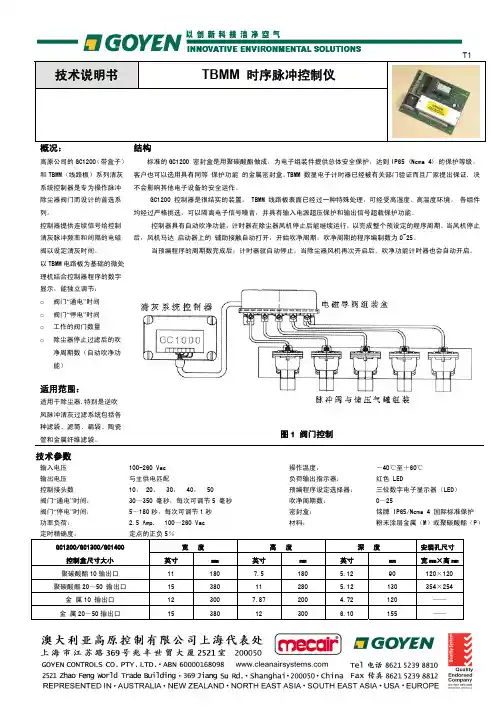
技术说明书 TBMM 时序脉冲控制仪概况:高原公司的GC1200(带盒子)和TBMM(线路板)系列清灰 系统控制器是专为操作脉冲 除尘器阀门而设计的首选系列。
控制器提供连续信号给控制清灰脉冲频率和间隔的电磁阀以设定清灰时间。
以TBMM 电路板为基础的微处理机结合控制器程序的数字显示,能独立调节: o 阀门“通电”时间 o 阀门“停电”时间 o 工作的阀门数量 o 除尘器停止过滤后的吹净周期数(自动吹净功能)适用范围:适用于除尘器,特别是逆吹风脉冲清灰过滤系统包括各种滤袋、滤筒、扁袋、陶瓷管和金属纤维滤袋。
结构标准的GC1200 密封盒是用聚碳酸酯做成,为电子组装件提供总体安全保护,达到IP65 (Nema 4) 的保护等级。
客户也可以选用具有同等 保护功能 的金属密封盒。
TBMM 数显电子计时器已经被有关部门验证而且厂家提出保证, 决不会影响其他电子设备的安全运作。
GC1200 控制器是很结实的装置, TBMM 线路板表面已经过一种特殊处理,可经受高湿度、高温度环境。
各组件均经过严格挑选,可以隔离电子信号噪音,并具有输入电源超压保护和输出信号超载保护功能。
控制器具有自动吹净功能,计时器在除尘器风机停止后能继续运行,以完成整个预设定的程序周期。
当风机停止后,风机马达 启动器上的 辅助接触自动打开,开始吹净周期。
吹净周期的程序编制数为0~25。
当预编程序的周期数完成后,计时器就自动停止。
当除尘器风机再次开启后,吹净功能计时器也会自动开启。
图1 阀门控制技术参数输入电压 100-260 Vac 操作温度: -40℃至+60℃ 输出电压 与主供电匹配负荷输出指示器: 红色 LED控制接头数10, 20, 30, 40, 50 预编程序设定选择器: 三位数字电子显示器(LED) 阀门“通电”时间: 30~350 毫秒,每次可调节5 毫秒 吹净周期数: 0~25阀门“停电”时间: 5~180秒,每次可调节1秒 密封盒:铭牌 IP65/Nema 4 国际标准保护 功率负荷: 2.5 Amp, 100~260 Vac 材料:粉末涂层金属(M)或聚碳酸酯(P)定时精确度:定点的正负5%GC1200/GC1300/GC1400宽 度 高 度深 度安装孔尺寸 控制盒尺寸大小 英寸 mm 英寸 mm 英寸 mm 宽mm×高mm 聚碳酸酯10输出口11 180 7.5 180 5.12 90 120×120 聚碳酸酯20~50 输出口15 380 11 280 5.12 130 354×254 金 属10 输出口 12 300 7.87 200 4.72 120 —— 金 属20-50输出口15380123006.10155——接线:请按照接线图连接。
Reference ManualOriginal InstructionsEstimated Execution Time and Memory Use for Logix5000 Controllers InstructionsCatalog NumbersThis publication provides estimated instruction execution times and memory use information for Logix5000™ controllers in RSLogix 5000® software and Studio 5000 Logix Designer® application projects.Controller/programming software compatibility varies based on controller family and catalog number. For information on compatibility, see the controller documentation.Summary of ChangesThis publication has been revised to add the IMPORTANT table on page 2 indicating that you need to open the PDF file in Adobe® Acrobat® instead of in a web browser.ControlLogix 55701756-L71, 1756-L72, 1756-L73, 1756-L74, 1756-L75GuardLogix 55701756-L72S, 1756-L73S ControlLogix 55601756-L61, 1756-L62, 1756-L63, 1756-L64, 1756-L65GuardLogix 55601756-L61S, 1756-L62S, 1756-L63S CompactLogix 53701769-L16ER-BB1B, 1769-L18ER-BB1B, 1769-L18ERM-BB1B1769-L24ER-QB1B, 1769-L24ER-QBFC1B, 1769-L27ERM-QBFC1B1769-L30ER, 1769-L30ERM, 1769-L30ER-NSE, 1769-L33ER, 1769-L33ERM, 1769-L36ERM1768 CompactLogix 1768-L43, 1768-L451768 Compact GuardLogix 1768-L43S, 1768-L45S1769 CompactLogix 1769-L23E-QB1B, 1769-L23E-QBFC1B, 1769-L23-QBFC1B, 1769-L31, 1769-L32C, 1769-L35CR, 1769-L32E, 1769-L35EDriveLogix 573020D PowerFlex 700S with DriveLogix Estimated instruction execution times are available for the following Logix 5000™ controllers:•ControlLogix® 5580 controllers •GuardLogix® 5580 controllers •CompactLogix™ 5380 controllers •Compact GuardLogix 5380 controllers For more information, see the Estimated Logix 5000 Controller Execution Times Reference Manual, publication LOGIX-RM002.2Rockwell Automation Publication 1756-RM087P-EN-P - July 2020Estimated Execution Time and Memory Use for Logix5000 Controllers Instructions Reference ManualPDF File AttachmentsMicrosoft® Excel® files are attached to this PDF file. The files list execution time and memory use data for Logix5000 controller instructions in RSLogix 5000 software or Logix Designer application projects.The following types of files are available:• A Microsoft Excel file that includes information for all controller families.• A Microsoft Excel files for individual controller families so you can focus on specific controller families.To use the attached files, click the Attachments link, that is, the paper clip icon, and double-click the desired file. IMPORTANT Download the PDF file to your computer and open it with Adobe Acrobat software.If you download the PDF file from Literature Library and open it locally on your computer, you can access, download, and use the Microsoft Excel files.You can open PDF files in some web browsers. However, not all web browsers provide the option to access and open attachments from a PDF file when displaying it.Estimated Execution Time and Memory Use for Logix5000 Controllers Instructions Reference Manual Studio 5000 EnvironmentThe Studio 5000® Engineering and Design Environment combines engineering and design elements into a common environment. The first element in the Studio 5000 environment is the Logix Designer application. The Logix Designer application is the rebranding of RSLogix 5000 software and is the product to program Logix5000 controllers for discrete, process, batch, motion, safety, and drive-based solutions.The Studio 5000 environment is the foundation for the future of Rockwell Automation® engineering design tools and capabilities. It is the oneplace for design engineers to develop all elements of their control system.Rockwell Automation Publication 1756-RM087P-EN-P - July 20203Publication 1756-RM087P-EN-P - July 2020 | Supersedes Publication 1756-RM087O-EN-P-January 2020Copyright © 2020 Rockwell Automation, Inc. All rights reserved. Printed in the U.S.A.Rockwell Otomasyon Ticaret A.Ş. Kar Plaza İş Merkezi E Blok Kat:6 34752 İçerenköy, İstanbul, Tel: +90 (216) 5698400 EEE Yönetmeliğine UygundurAllen-Bradley, CompactLogix, ControlLogix, DriveLogix, expanding human possibility, GuardLogix, Logix5000, Logix 5000, PowerFlex, Rockwell Automation, Rockwell Software, RSLogix 5000, Studio 5000, and Studio 5000 Logix Designer are trademarks of Rockwell Automation, Inc.Acrobat and Adobe are trademarks of Adobe Systems, Inc.Excel and Microsoft are trademarks of Microsoft Corporation.Trademarks not belonging to Rockwell Automation are property of their respective companies.Rockwell Automation maintains current product environmental compliance information on its website at rok.auto/pec .Rockwell Automation SupportUse these resources to access support information.Documentation FeedbackYour comments help us serve your documentation needs better. If you have any suggestions on how to improve our content, complete the form at rok.auto/docfeedback .Technical Support CenterFind help with how-to videos, FAQs, chat, user forums, and product notification updates.rok.auto/support KnowledgebaseAccess Knowledgebase articles.rok.auto/knowledgebase Local Technical Support Phone NumbersLocate the telephone number for your country.rok.auto/phonesupport Literature LibraryFind installation instructions, manuals, brochures, and technical data publications.rok.auto/literature Product Compatibility and Download Center (PCDC)Download firmware, associated files (such as AOP, EDS, and DTM), and access product release notes.rok.auto/pcdc。
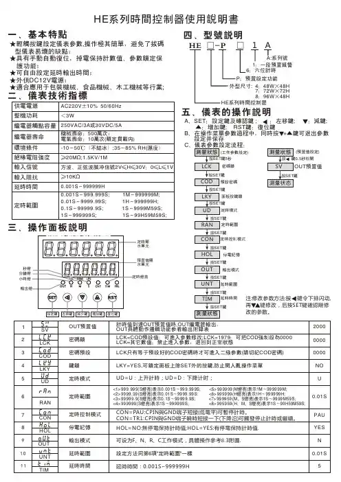
★轻触按键设定仪表参数,操作极其简单,避免了拔码 型仪表易坏的缺点;★具有手动自动复位,掉电保持计数值、参数锁定保 护功能;★可自由设定延时输出时间;★外供DC12V电源;★适合应用于包装机械、食品机械、木工机械等行业;HE系列时间控制器使用说明书一、基本特点四、型号说明二、仪表技术指标三、操作面板说明五、仪表的操作说明供电电源整机功耗继电器触点容量继电器寿命绝缘电阻强度环境条件输入信号输入阻抗延时时间定时范围AC220V±10% 50/60Hz <3W250VAC/3A或30VDC/5A 机械寿命:500万次;电气寿命:10万次(额定负载内)≥20M Ω;1.5KV/1M-10~50℃(不结冰);35~85% RH(湿度)方波、正弦波脉冲信号2V≤H≤30V:0≤L≤1V≥10K Ω0.001S ~999999H0.001S ~999.999S; 1M ~999999M;0.01S ~9999.99S; 1H ~999999H;0.1S ~99999.9S; 1S ~9999M59S;1S ~999999S; 1S ~99H59M59S;A、SET:设定键及确认键 ; :左移键; :减键; ▲:增加键; RST键:复位键B、在操作菜单参数过程中,同时按 +▲键可退出参数 设定并保存(预置值设定)小时灯秒灯分钟灯面板按键锁OUT预置值密码锁定时范围停电记忆输出模式定时模式注:修改参数方法:按 鍵令下排闪动,再 键修改,后按SET 鍵確認剛修改的參數。
注:若本接線图与实际仪表接線图有差别, 请您按实际仪表接線图接線。
8.1 接線注意事项8.2 接線范例8.3 输出方式逻辑图(1)输入导線不宜过长,建议输入線使用屏蔽線。
(2)输入信号線应远离仪表电源線,动力电源線和负荷線,以避免产生杂讯干扰。
(3)对电气回路和非带电金属体进行耐压实验等场合,请将计数器从回路拆下或短路(有可能损坏CMOS电路)★RST为复位端子为高电平触发★CPIN为触发端子为低电平触发输出输出說明:1.當CON 設為PAU 時,控制端短接可以暫停計是時。

使用说明书IMS-A系列伺服控制器简易调试说明时光科技有限公司目录前言 (2)概要 (3)主回路接线图 (4)控制回路接线图 (5)输入接口介绍 (6)输出接口介绍 (7)编码器信号介绍 (8)单项脉冲列信号介绍 (9)模拟量信号介绍 (9)通讯信号介绍 (10)跳线、拨码开关介绍 (10)操作面板的使用 (12)故障报警含义及解决办法 (16)系统参数一览表 (18)参数的调节与初始化 (20)前言请在产品调试之前,详细阅读调试说明书,请妥善保存随机附送的说明书并交由该机器的使用者。
伺服控制器是精密的电子电气产品,为了操作者及机械设备的安全,请交于专业的电气人员安装试车及参数调整,并请仔细阅读该说明书,若有任何疑惑请联系本公司洽谈,我们的专业人员会热诚为您服务。
⏹概要IMS-A系列伺服控制器是时光科技有限公司最新推出的全数字化交流异步电动机伺服控制器,具有结构紧凑、使用方便、可靠性高的优点,适用于各种高精度控制的场合。
产品的技术特点●硬件构成先进可靠⏹专用CPU对电机进行全数字化控制。
⏹智能化功率模块。
⏹优化设计的模块化功能电路。
⏹电流、速度、位置三闭环系统。
⏹内置制动单元。
●软件功能完善灵活⏹实时操作系统,滑差频率矢量控制。
⏹专用、开放、简单易学的QMCL运动控制语言。
●控制功能全面精确⏹稳定的转速控制。
⏹精确的位置控制。
⏹优良的转矩控制。
●集成PLC控制功能,各种可编程I/O、A/D、D/A、脉冲列接口及通信接口齐全。
●配用本公司SM系列电机,可达到最高3倍的过载使用能力。
产品型号词语说明:1、主控板类型:·双PG型,除控制器自身所控电机的PG接口外,另配一个外部轴PG输入接口。
·单PG型,只有控制器自身所控电机的PG接口,无外部轴PG输入接口2、PG(Pulse Generation):在本说明书中特指用于电机控制和外部给定的脉冲发生器或编码器。
本说明书里涉及到的PG,都是线驱动增量型编码器。
时间控制器说明书时间控制器说明书1:简介时间控制器是一种用于控制定时任务的设备,它通过设定时间参数,实现对其他设备的开关、调节等操作。
本说明书旨在为用户提供详细的操作步骤和注意事项,以帮助用户正确使用时间控制器。
2:产品规格时间控制器的规格如下:- 尺寸:毫米 x 毫米 x 毫米- 重量:克- 输入电压:AC V- 最大载荷电流:安培- 工作温度:-°C 至 +°C3:组件及功能时间控制器由以下组件组成,每个组件都具有特定的功能:3.1 显示屏:用于显示当前时间和设置参数。
3.2 按钮:用于选择菜单和操作参数设置。
3.3 开关:用于手动控制设备的开关状态。
3.4 时间调节按钮:用于调节时间参数。
4:安装步骤在安装时间控制器之前,请确保断开电源,并按照以下步骤进行操作:4.1 将时间控制器固定在所需的位置,并确保其安装牢固。
4.2 连接电源线,并确认电源线的连接正确无误。
4.3 打开电源,启动时间控制器。
5:使用说明时间控制器具有以下功能:5.1 时间设置:通过按下时间调节按钮,在显示屏上设置当前时间。
5.2 定时开关:在定时菜单下,选择开关状态和时间参数,实现设备的定时开关。
5.3 循环定时:在循环定时菜单下,选择循环周期和设备操作时间,实现设备按照设定周期循环运行。
5.4 周期调节:在周期调节菜单下,选择设备的工作周期和休息周期,实现设备的定期工作和休息。
5.5 手动开关:通过手动操作按钮,实现对设备的开关控制。
6:常见问题解答以下是一些常见问题的解答,供用户参考:6.1 时间显示不准确:请确保设置的当前时间准确无误,并检查电源是否正常。
6.2 定时任务无法执行:请确认定时任务的时间参数是否正确,并检查设备的接线是否正确。
6.3 时间控制器无法正常工作:请检查电源是否正常,如果问题仍然存在,请联系售后服务。
7:附件本文档涉及的附件包括:- 时间控制器使用手册- 时间控制器安装图纸8:法律名词及注释本文档中涉及的法律名词及其注释如下:- AC:交流电(Alternating Current),指电流在正负方向上交替变化的电力。

北京东方润泽生态科技股份有限公司免费热线:4008107860目录第一章控制器简介 (3)第二章控制器组成 (4)一、控制器内部结构及用户界面: (4)二、TMC-424控制器特点 (6)第三章编制灌溉程序 (7)一、设置当前时间及日期 (7)二、选择灌溉程序 (7)三、设置站点运行时间 (7)四、设置灌溉程序启动时间 (7)五、设置灌溉计划 (8)六、设置周灌溉模式 (8)七、设置奇/偶天灌溉模式 (8)八、设置间隔灌溉模式 (9)第四章特殊功能 (10)一、井位恢复/站点延迟功能 (10)二、程序叠加/顺序执行选择 (10)三、程序记忆清除 (11)四、设置主阀/水泵工况状态 (11)五、显示屏语言选项 (11)六、时间显示格式 (12)七、站点运行时间显示格式 (12)八、手持遥控操作 (12)第五章手动操作 (13)一、手动站点操作 (13)二、通过灌溉程序实现手动操作 (13)三、多程序同时手动运行设置 (14)第六章流量传感器设置 (15)一、流量传感器设置 (15)二、流量传感器忽略设置 (16)第七章控制器其它功能 (17)一、水量预算功能 (17)二、控制器自检功能 (17)三、程序复查功能 (17)四、降雨延迟功能 (18)欢迎使用TORO公司出品的TMC424系列模块控制器,该控制器使用灵活方便,扩展输出模块有4站和8站两种,可自由组合、即插即用,输出站点范围4—24站(增加模块),适用于各种绿地及运动场的灌溉控制。
控制器输出模块性能参数如下表所示:TMC-424控制器具有以下特点:•先进的模块化扩展方式,用户界面简单易懂。
•断电记忆功能,灌溉程序可保持数年。
•四个独立的灌溉程序。
•16次程序启动时间,可由各灌溉程序任意组合。
•可选择周灌溉模式、间隔灌溉模式、奇/偶天灌溉模式等。
•支持闰年日历。
•可按设定的日期长度进行轮灌,也可按日期的奇、偶交替轮灌。
•站点运行时间可调,范围为1秒—8小时。
PJ-62C可编程单路时控模块说明书新一代PJ1280C微电脑可编程时控模块, 驱动LCD,程序优化稳定,具备超强的抗干扰能力,脉冲测试通过3500v 电磁干扰,属升级加强版,具备以下功能和特点:1、设定次数:每天10组编程定时(10开10关);2、控制周期:可日控或周控循环(可实现每天不同定时设置);3、时控范围:1分-168小时;4、超强的抗干扰;5、模块输出端口有两种连接方式:焊盘式连接方式和SIP标准排线连接方式6、我司有中文、英文、常温、宽温多种模块配置品种,供客户选择使用。
一、主要技术指标1、工作电压:1.5V2、静态耗电流:小于或等于3uA3、晶振频率:32768Hz4、工作温度:-10度~ +60度;(宽温型为:-40度~ +85度)5、存储温度:-20度~+70度6、计时误差:< +-0.5秒/天7、输出口驱动电流:100uA二、定时IC操作键盘及LCD显示外观图模块厚度:6.6 mm ;若计算模块背面晶振元件高度,最大厚度则为:9.5 mm(英文LCD显示示意图)三、操作方式§时钟状态设定/调整在时钟显示界面,按住[时钟]键不放,同时按[小时]或[分钟]或[星期]键时可调整时钟或星期;按[自动/手动]键,可进行[开/自动/关]状态转换(当按至“开”状态时:系统一直有输出;当按至“关”状态时:系统关闭输出;当按至“自动”状态时:系统则执行已设定的时间开关程序,正常工作时应放在“自动”位置)。
§定时状态设定/调整1、在键盘锁解除后,按[定时]键进入定时状态,每按一次[定时]键时都进入下一组定时设定界面;若连续按[定时]键:1开→1关→2开→2关→……9开→9关→10开→10关→时钟界面→1开→1关→2开→2关→……反复循环2、在定时设定界面,按[小时]键时可调整当次定时之小时3、在定时设定界面,按[分钟]键时可调整当次定时之分钟4、在定时设定界面,按[星期]键时可调整当次定时之星期设定选择;在每一“开”或每一“关”设定时都有15种星期组合模式供选择,连续按[星期]键,15星期组合显示可进行如下循环:周一周二周三周四周五周六周日→周一→周二→周三→周四→周五→周六→周日→一三五→二四六→六日→一二三→四五六→一二三四五→一二三四五六→周一周二周三周四周五周六周日→……反复循环,用户根据控制需要可进行星期组合的设定选择。
控制器使用说明书12/24V自动识别(10A)一、按下图连接控制器:1、连接控制器与蓄电池(12V或24V蓄电池)在保证安装位置的情况下,尽可能减少连线长度,以减少线损,按照不大于6A/mm2的电流密度选择铜导线截面积,注意极性不要接反。
连接正确,显示5、4、3、2、1、0倒计时后,自动识别电池电压,闪烁显示“U12.0或U24.0”,然后显示当前电瓶电压"UXX.X",充电灯亮,因无电池板,倒数3秒计时后关充电灯,待机灯亮。
如无显示,检查:1、正负极连接是否正确,2、蓄电池是否电量充足。
2、连接光伏电池组件按图接光伏电池组件,注意+、-极,不要反接,如果有光,检测到后3秒倒计时充电指示灯亮,待机指示灯关,如无反应,检查连接对否。
3、连接负载(直流用电器)将负载按图接到控制器上, +、-极,不要接反,以免烧坏用电器。
接好后测试一下,系统默认的工作方式为手动开关方式,按下A键,输出A指示灯亮,对应A输出开,再按一下A键,输出A指示灯关,A输出关,B路应用同A路。
(USB5V手机充电口开关由按键B控制)二、面板说明:1、指示灯:1、输出:有两个输出指示灯,输出A,输出B指示,对应端子有输出时指示灯亮,其中在光控定时工作方式时对应指示灯闪动计时,频率为1秒。
2、过流:当系统输出过流时控制器过流指示灯亮,自动关闭输出,过流指示灯亮说明系统负载过大超出设定工作电流或是输出端短路,检查后按R键解除。
3、充电:系统正确连接光伏电池组件并有光照的情况下充电指示灯亮,当系统快要充满时充电灯闪动,进入PWM浮充充电。
4、光控:光控模式打开后,光控指示灯亮。
5、待机:手动方式下,无输出时待机指示灯亮,光控方式下,定时时间到自动关输出,待机指示灯亮。
待机指示灯闪动说明系统欠压,欠压状态下无法开启输出,电池充电到欠压返回值时待机指示灯停闪,输出可正常开启。
2、按键:返回键/显示切换键:参数设定时退回到上一级菜单,显示时用于切换显示内容。
Sequence Injection ControllerVersion 5.5 Sequence Injection ControllerINSTRUCTION MANUALTYPE ACT-D800Thank you for using YUDO production 感谢贵公司使用YUDO 产品Contents 目录1、Environments ……………………………………………………2使用环境2、Composition of Control Module ……… …………………………2PCB 结构3、Central Processing Unit ……………………………………………2主要控制装置4、Input ………………………………………………………………2输入因素5、Display ……………………………………………………………3显示因素6、Output ………………………………………………………………3输出因素7、Start to Run…………………………………………………………4使用说明8、Menu Setting………………………………………………………5动态说明9、Mode Specification ………………………………………………7模式规格10、System Application ………………………………………………8系统应用程序11、Wiring Specification………………………………………………9外部线连接图Before using the product ,please read this instruction manual carefully to avoid any damage due to improper usage. If you have any questions, please do not hesitate to contact our Head Office or YUDO Territory Sales Branch.使用本产品前,敬请仔细阅读此手册,以免在操作过程中的失误。
继电器时间控制器使用说明书型号:YHZ-5271.概述该仪表可完成设定时间定时触发动作的工作情况。
控制器采用Atmel 公司的A Tmega128芯片作为控制核心,可以完成每日两次定时,可设定动作状态的功能。
² 精确到秒的定时时间,时间设定从00:00:00到23:59:59; ² 可分类选择定时时间,按照“天”计划(周一到周日每天各不相同)的定时时间,以及按照“周”计划(工作日和休息日不相同)的定时时间或按照“节假日”计划的定时时间;² 用户设定优先级,以确定当“天”计划定时时间与“周”计划定时时间或“节假日”计划定时时间冲突时,按照哪个计划执行;² 全部参数可通过面板、上位机设定,可查询,并设置;有密码保护,可自行设定密码;² 可显示、修改当前日期、时间;² 上位机可随时要求仪表发送测量值和流量值,通讯接口RS232,波特率可设定为300、600、1200、2400、4800、9600。
2.显示与按键图1 继电器时间控制器面板示意图(1).仪表采用无字库的液晶显示屏显示数据信息,分两行显示,每行最多可显示7位汉字或15位数字,小数点不占位。
(2).仪表设计为4按键操作面板,其具体功能简介如下:按键名称功能菜单键(SET) ● 1.在设置状态下,使当前功能界面向后翻页并保存当前界面的数据。
2.在设置状态下,配合左移键可跳转到下一功能界面。
减少键(DOWN) 1.在设置状态下,使数据当前位减一;增加键(UP ) 1.在设置状态下,使数据当前位加一;左移键(LMOVE) 1.在设置状态下,使光标左移。
3.菜单设置及参数修改(1)菜单设置系统上电初始化完成以后,液晶显示屏显示的是当前日期。
时间,如:图1的屏幕所示“日期06-09-20”、“时间14:51:20”。
每一秒都会自动刷新时间。
除了基本显示外,所有参数的修改查看需要有系统权限,即需要密码才能进入对各个参数进行查看或者修改操作。