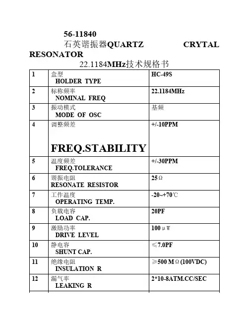
陶瓷谐振器25M规格书
- 格式:pdf
- 大小:310.51 KB
- 文档页数:10
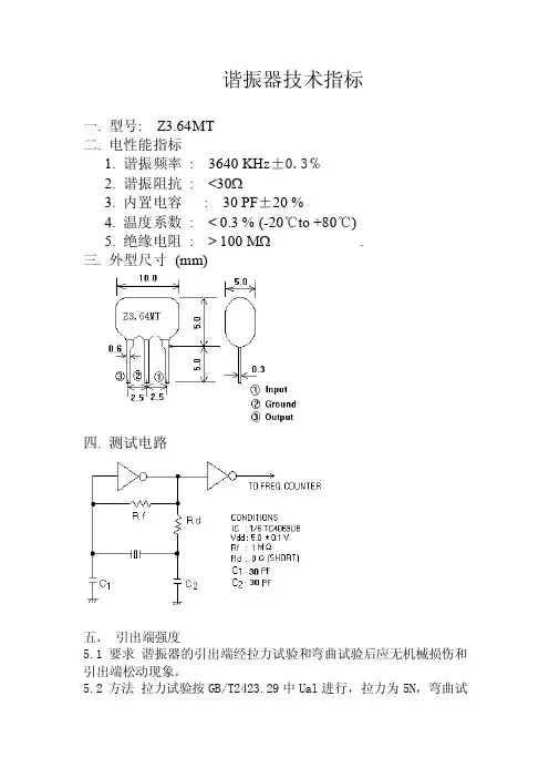
谐振器技术指标一. 型号: Z3.64MT二. 电性能指标1. 谐振频率: 3640 KH z±0.3℅2. 谐振阻抗: <30Ω3. 内置电容: 30 PF±20 %4. 温度系数: < 0.3 % (-20℃to +80℃)5. 绝缘电阻: > 100 MΩ.三. 外型尺寸(mm)四. 测试电路五.引出端强度5.1 要求谐振器的引出端经拉力试验和弯曲试验后应无机械损伤和引出端松动现象。
5.2 方法拉力试验按GB/T2423.29中Ual进行,拉力为5N,弯曲试验按GB/T2423.29中Ub方法2进行六.可焊性6.1 要求谐振器的引出端应易焊,沾锡良好,焊料能与引出线润湿。
6.2 方法焊性试验按GB/T2423.28试验Ta方法1进行,采用235℃焊槽法引出端浸入离谐振器主体2 - 2.5mm处。
七.耐焊接热7.1 要求谐振器应能接受焊接热的作用,其外观和电气性能符合4.3和4.4条的规定。
7.2 方法耐焊接热试验按GB/T242.28试验Tb方法1A进行,采用260℃的焊槽持续的时间为5±1秒,试验后回复2h 。
八.振动8.1 要求谐振器经试验后,外观和电气性能符合4.3和3.4条的规定。
8.2 方法按GB/T2423.10的规定振动频率范围为10Hz - 55Hz - 10Hz ,振幅为0.75mm ,扫频循环次数为15,三个方向。
九.碰撞9.1 要求谐振器经碰撞试验后,外观和电气性能符合4.3和4.4条规定。
9.2 方法按GB/T2423.6的规定加速度为250m/s2,以谐振器的互相垂直的三个方向个碰撞1000±10次。
十.温度变化10.1 要求谐振器在-20℃和+80℃温度下承受三次温度变化后。
外观和电气性能符合4.3和4.4条的规定。
10.2 方法按GB/T2423.22试验Na的规定进行,保持时间为30min,转移时间不大于3min,恢复时间为24±2h 。
谐振器CRB455E规格书1.范围本规格书包括了微处理器时钟振荡用455KH Z陶瓷谐振器的特性2.规格书编号:JZY200403353.产品型号:CRB455E4.电特性:4.1 谐振器频率精度:455±2KH Z4.2 谐振阻抗:20Ωmax4.3 电容量:280PF±20%4.4 谐振频率温度稳定性:±0.3%(-20℃—— +80℃)max4.5 耐电压: 50V DC max4.6 输入电压:15Vp-p max4.7 绝缘电阻:100MΩ(100V﹑ DC)max5.测试条件5.1 引出线拉力:负载1kg。
5.2 振动:600-3300H Z变频,振幅1.5mm.小时。
5.3 跌落:随机抽样,将谐振器跌落于30cm高水泥地面。
5.4 焊接:锡槽内锡液温度为230℃±5℃,焊接时间为5秒±0.5。
5.5 耐焊接温度:锡槽内锡液温度为350℃±10℃,焊接时间为3 秒,谐振器引出线浸入锡液面至离外壳2mm处为极限,试验后恢复1小时再测量。
5.6 抵抗湿热度:温度40℃±2℃,湿度90%,时间为100小时。
5.7 环境温度:-20--80℃。
5.8 贮存温度:-40--85℃。
5.9 测试结果:在以上的许可工作条件下测试,谐振器的频率可维持在455KH Z ±2KH Z,且工作稳定正常。
5.10 产品老化率:±0.5% max。
6.测试电路:谐振频率按图所示的标准电路进行测试。
6.外型尺寸:(见图)晶众业电子有限公司工程部制。
空调事业部企业标准晶振和陶瓷谐振器空调事业部发布空调事业部企业标准晶振和陶瓷谐振器1范围本标准规定了晶振和陶瓷谐振器(以下统一简称振荡器)的技术要求、试验方法、检验规则、标志、包装、贮存和运输等。
本标准适用于空调控制器用晶振和压电陶瓷谐振器。
2引用标准下列标准所包含的条文,通过在本标准中引用而构成为本标准的条文。
本标准出版时,所示版本均为有效。
所有标准都会被修订,使用本标准的各方应探讨使用下列标准最新版本的可能性。
GB/T2828.1-2003 计数抽样检验程序第1部分:按接收质量限(AQL)检索的逐批检验抽样计划GB/T 12274-1990 石英晶体振荡器总规范GB/T 12275-1990 石英晶体振荡器型号命名方法GB/T 12859-1991 电子设备用压电陶瓷谐振器总规范GB/T 12862-1991 电子设备用压电陶瓷谐振器分规范——高频压电陶瓷谐振器GB/T 12863-1991 电子设备用压电陶瓷谐振器空白详细规范高频压电陶瓷谐振器评定水平E GB/T 15020-1994 电子设备用石英晶体元件空白详细规范电阻焊石英晶体元件评定水平E QJ/MK01.003-2000a 逐批检查计数抽样程序及抽样表进货检验3术语和定义3.1振荡频率从使用振荡器的振荡回路馈给的输出信号频率。
3.2谐振电阻基频或泛音振动模式的最小谐振阻抗。
其值等于等效电路串联谐振臂的电阻,并与机械Q值有关。
3.3室温频差指其他条件不变,室温25℃±2℃下,振荡器输出频率相对于标称值的最大允许偏离。
3.4总频差指其他条件不变,在工作温度范围内,振荡器输出频率相对于标称值的最大允许偏离。
3.5类别温度范围空调事业部1谐振器设计所确定的能连续工作的环境温度范围,该范围取决于它的相应类别的温度极限值。
3.6上限类别温度振荡器设计所确定的能连续工作的最高环境温度。
3.7下限类别温度振荡器设计所确定的能连续工作的最低环境温度。
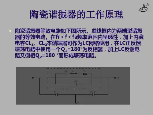
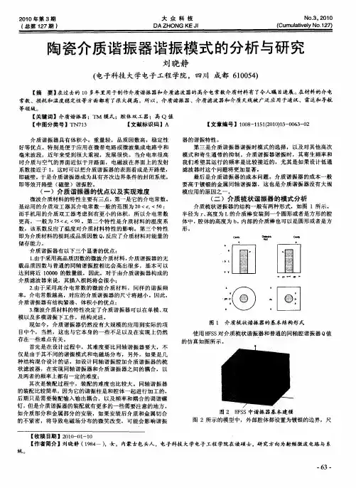
陶瓷谐振器的工作原理
陶瓷谐振器等效电路如下图所示。
虚线框内为两端型谐振器的等效电路。
在fr<f<fa频率范围内呈感性,加上内
藏电容CL
1、CL
2
本谐振器可作为LC网络使用,在LC正反馈
振荡电路中使用一个Q
1=180°为反相器,加上LC反馈电路
又倒相Q
2
=180 °而形成振荡电路。
陶瓷谐振器的振荡条件
振荡条件:回路增益G=10log(α*β)≥0相移Q=Q 1+Q 2=360°×n (n=1、2、3……)
基本振荡电路回路增益测量电路
V10.01μF
R 1=50ΩT.G
Output=-20dBm
2PF 10MΩ
Rf=1MΩ
Ceramic
Resonator OUT
V 0IC:TC74HCU04
Vcc=5.0V
G=10Log(V 0/V 1)≥0~
陶瓷谐振器基本参数▪我司陶瓷谐振器分为ZTA型(不带内置电容)和ZTT型(带内置
电容),相应等效电路和阻抗和
相位特性图如:
▪(ZTA型)
▪(ZTT型)
陶瓷谐振器基本参数
▪C0:静电容;C1:动态电容;L1动态电感;
R1:动态电阻;CL1、CL2内置负载电容。
▪Zr:谐振电阻,近似于R1;
▪Fr:谐振频率,Fr=1/2π√L1C1;
▪Fa:反谐振频率,Fa=1/2π√L1C1C0/(C1+C0)
=Fr√1+C1/C0;
▪FOSC:振荡频率,FOSC=Fr√1+C1/(C0+CL);。
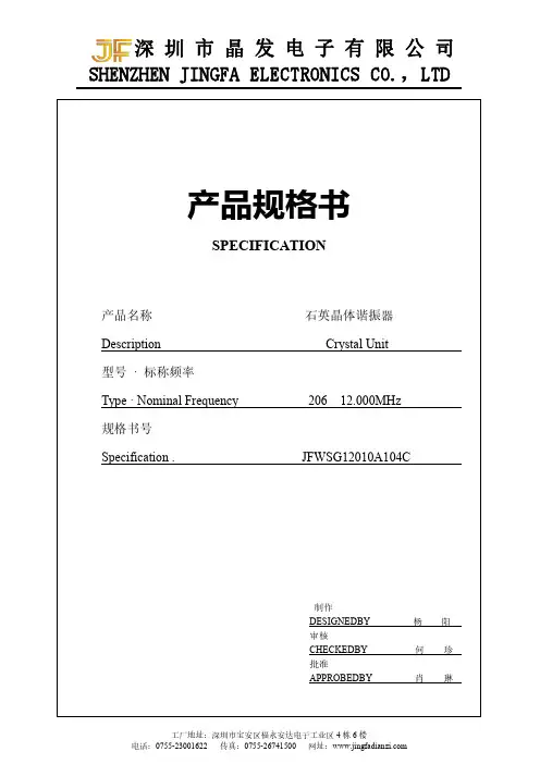
产品规格书SPECIFICATION产品名称石英晶体谐振器Description Crystal Unit型号·标称频率Type·Nominal Frequency20612.000MHz规格书号Specification.JFWSG12010A104C制作DESIGNEDBY杨阳审核CHECKEDBY何珍批准APPROBEDBY肖琳石英晶体谐振器(柱状)RoHS Compliant Standard TDXLF-206-12.000MHz10PFSTANDARD SPECIFICATIONS標準規格标称频率Nominal Frequency12.000MHz负载电容Load Capacitance10pF工作温度范围Operating Temperature-20℃~+70℃频率公差Frequency Tolerance±10ppm25℃温度频差±10PPM(-20~+70之间)等效阻抗<80Ω激励电平Level of Drive50U W绝缘电阻:50M(插脚间加DC100V±5V)年老化率Aging±5ppm/year静电容<5PF可靠性1Reliability(Mechanical and Environmental Endurance)Page1of2 NO Test Items Test Method and Condition Requirements1振動Vibration (1)振動頻Vibration Frequency10to55Hz(2)振動幅度Vibration Amplitude1.5mm(3)周期Cycle Time1-2min(10-55-10Hz)(4)振動方向Direction X.Y.Z(5)振動時間Duration2h/each direction頻率變化最大:±10ppm覆蓋The dipped surface of theleads should be at least95%covered with continuous newsolder coating2衝擊Shock 從75cm高的地方自由跌落3次到30mm厚的硬木板上3Times free drop from75cmheight to hard wooden board of thicknessmore than30mm頻率變化最大:±10ppmFrequency Change:±10ppm Max.電阻變化最大:5kohmResistance Change:5kohm Max.3氣密性Leakage 晶體放入氦加壓罐內,充入氦氣壓力0.5-0.6Mpa保持1小時;然後使用氦質譜檢漏儀測試。
CMRS-MS008March.05.2004
CERAMIC RESONATOR
S-Cera CO.LTD.
384-14,SHIN-DONG,PALDAL-GU,SUWON,
KYUNGGI-DO,KOREA442-390
1.SCOPE
This specification is applied to the ceramic resonator in IC oscillation circuit.
2.PART NUMBER
3.ELECTRICAL CHARACTERISTICS
The MHz ceramic resonator must meet the following performance when tested in the circuit indicated in figure 1and figure 2.
●Measuring Condition :Temperature (+15~35℃),
Humidity (45~85%RH)
22:Internal Code
E :Embossed Plastic Reel &Reel Taping 0S :SMD Type
T :Ceramic Matrial Type
25P0:Oscillating Frequency(25MHz)R :Resonator
IF
:
Intermediate Frequency
Figure1.Test Circuit for Oscillating Frequency
Figure2.Measurement for Resonant Impedance
4.DIMENSIONS &STRUCTURE
●PCB Soldering Land Dimensions
●
Marking
0.5±0.2
0.5±0.20.5±0.2
25.00T *#
Land
*#Internal Management Code
*:Monthly Code,#:Weekly Code
(Unit :mm)
5.ENVIRONMENTAL&PHYSICAL CHARACTERISTICS
CMRS-Pb008
TABLE1
6.PACKAGING STANDARD
The products should be packaged for protecting from the accident which could be caused during transportation or preservation,and part name,quantity and inspection lot No.shall be given to the each minimum packing unit.
Note)1Tray contains 3,000pcs Resonator.
WEIGHT :0.04g/pcs
◎Reel
◎Inner Box
◎Outer Box
(a)Reel (b)Inner Box (c)Outer Box
195
mm
mm
7.CAUTIONS FOR USE
7-1.Resonator might be damaged when an excess stress is applied.
7-2.Cleaning or washing of the component is not acceptable due to non sealed construction.
Cleaning conditions,such as kinds of cleaning solvents,immersion time and temperatures
etc,after soldering shall be checked by experiments before production.
7-3.Conformal coating of the component is acceptable.However,the resin material,curing temperature,and other process conditions should be evaluated to confirm stable electrical
characteristics are maintained.
7-4.Irregular or stop oscillation may occur under unmatched circuit conditions.And it shall be noted that oscillating frequencies of the Ceramics Resonator may drift depending on IC applied (the type names,the manufacturer)and capacitance of external capacitors(C1,C2)and the
circuit design in figure1.
8.LIMITATION FOR USAGE
8-1.The component is manufactured and promoted to be used in general electronic of AV,home appliance,communication,measurement equipments and machine tools.
8-2.Contact us before using our products for the following applications.
1)Aircraft equipment
2)Aerospace equipment
3)Undersea equipment
4)Medical equipment
5)Transportation equipment
6)Traffic signal equipment
7)Disaster prevention/Crime prevention equipment
8)Data-processing equipment
9)Applications of similar complexity or with reliability requirements comparable to
the applications listed in the above.
These applications requires especially high reliability in order to prevent defects which might
directly cause damage to other party's life,body or property.
9.NOTICE
9-1.This specification mentions the quality of the component as a single unit.Insure the component is thoroughly evaluated in your application circuit.
9-2.Be sure to provide an appropriate fail-safe function on your product to prevent a second damage that may be caused by an abnormality or failure related to our product.
9-3.Please do not use this component in any application that deviates from its intended use as noted within the specification.
9-4.Return one of this specification after your signature of acceptance.In case of no return within three months from submission date,this specification should be treated as accepted.
■DIMENSIONS OF CARRIER TAPE
■DIMENSIONS OF TAPING REEL
(Unit:mm)2.8±0.1
2.3+0.1
-0.05
180.00
φ180±2.0。