欧姆龙定时器h5cn说明书
- 格式:pdf
- 大小:590.47 KB
- 文档页数:2
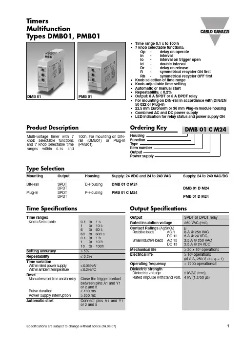
•Time range 0.1 s to 100 h•7knob selectable functions:Op-delay on operateIn-intervalIo-interval on trigger openId-double intervalDr-delay on releaseR-symmetrical recycler ON firstRb-symmetrical recycler OFF first•Knob selection of time range•Knob-adjustable time setting•Automatic or manual start•Repeatability: ≤0.2%•Output: 8 A SPDT or 8 A DPDT relay•For mounting on DIN-rail in accordance with DIN/EN50 022 or Plug-in•22.5 mm Euronorm or 36 mm Plug-in module housing •Combined AC and DC power supply•LED indication for relay status and power supply ONMulti-voltage tim er with 7 knob selectable functions and 7 knob selectable tim e ranges within 0.1s and 100h. For mounting on DIN-rail (DMB01) or Plug-in (PMB01).TimersMultifunctionTypes DMB01, PMB01Product DescriptionType SelectionMounting Output Housing Supply: 24 VDC and 24 to 240 VAC Supply: 24 to 240 VAC/DC DIN-rail SPDT D-Housing DMB 01 C M24DPDT DMB 01 D M24Plug-in SPDT P-Housing PMB 01 C M24DPDT PMB 01 D M24Time Specifications Output SpecificationsDMB 01PMB 01DMB01, PMB01Function OpDelay on operateThe tim e period begins as soon as the trigger contact is closed.At the end of the set delay tim e the relay operates and doesn't release until the trig-ger contact is closed again or the power supply is dis-connected. If the trigger contact is closed before the end of the delay tim e, the device resets and a new time period starts.Function In IntervalThe relay operates and the tim e period begins as soon as the trigger contact is closed. The relay releases at the end of this period or when the power supply is disconnected. The relay operates again when the trigger contact is closed again. If the trigger contact is closed before the end of the delay tim e, the relaykeeps ON and a new tim e period starts.Function IoInterval on trigger open The relay operates and the tim e period begins as soon as the trigger contact is opened. At the end of the set delay or when the power supply is disconnected the relay releases. The relay operates again when the trigger contact is opened again. If the trigger contact is opened before the end of the delay tim e the relay keeps ON and a new tim e period begins.Function Id Double intervalThe relay operates and the tim e period begins as soon as the trigger contact is closed. The relay releases at the end of this period or when the power supply is disconnected. When the trigger contact is openedthe relay operates again for the set delay period. If the trigger contact is opened before the end of the first tim e period the second one begins; if the trigger contact is closed before the end of the second tim e period the relay keeps ON and the first time period begins again.Function DrDelay on releaseThe relay operates as soon as the trigger contact is closed. The tim e period begins when the trigger con-tact is opened. The relay releases at the end of the set delay tim e or when the power supply is disconnect-ed. The relay operates again when the input contact is closed again. If it is closed before the end of the delay tim e the relay keeps ON, a new tim e period begins as soon as the contact is opened again.Function RSymmetrical recycler, ON-time period firstThe relay operates and the tim e period begins as soon as the input contact is closed. After the set delay period the relay releases for the sam e tim e period. This sequence continues with equal ON- and OFF-tim e periods until the power sup-ply is interrupted.Function RbSymmetrical recycler,OFF-time period firstThe tim e period begins as soon as the input contact is closed. The relay is OFF during the set delay period,after this time it operates for the sam e tim e period. This sequence continues with equal OFF- and ON-tim e periods until power supply is interrupted.Supply SpecificationsGeneral SpecificationsFunction and Time SettingMode of OperationUpper knob:Setting of function:Op -delay on operate In -intervalIo -interval on triggeropenId -double interval Dr -delay on releaseR -symmetrical recycler(ON first)Rb -symmetrical recycler(OFF first)Centre knob:Tim e setting on relative scale: 1 to 10 with respect to the chosen range.Lower knob:Setting of time range.DMB01, PMB01Additional LoadIt's possible to wire an addi-tional load (i.e. a relay) between pins Y1 and A2, or 5and 10, driven by the trig-ger contact without dam ag-ing the device (see wiringdiagram).Yellow LED working modeTiming: Slow blinkingRelay ON: See operationdiagramsIncorrect knobs position:Fast blinkingMode of Operation (cont.) Operation DiagramsOperation Diagrams (cont.)DMB01, PMB01DimensionsWiring Diagrams。
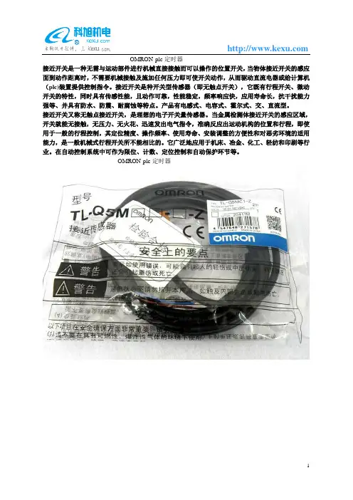
OMRON-plc定时器
接近开关是一种无需与运动部件进行机械直接接触而可以操作的位置开关,当物体接近开关的感应面到动作距离时,不需要机械接触及施加任何压力即可使开关动作,从而驱动直流电器或给计算机(plc)装置提供控制指令。
接近开关是种开关型传感器(即无触点开关),它既有行程开关、微动开关的特性,同时具有传感性能,且动作可靠,性能稳定,频率响应快,应用寿命长,抗干扰能力强等、并具有防水、防震、耐腐蚀等特点。
产品有电感式、电容式、霍尔式、交、直流型。
接近开关又称无触点接近开关,是理想的电子开关量传感器。
当金属检测体接近开关的感应区域,开关就能无接触,无压力、无火花、迅速发出电气指令,准确反应出运动机构的位置和行程,即使用于一般的行程控制,其定位精度、操作频率、使用寿命、安装调整的方便性和对恶劣环境的适用能力,是一般机械式行程开关所不能相比的。
它广泛地应用于机床、冶金、化工、轻纺和印刷等行业。
在自动控制系统中可作为限位、计数、定位控制和自动保护环节等。
OMRON-plc定时器。

CJ系列内置I/OCJ1M CPU22/CPU23 CPU单元操作手册2002年11月ivv注意:OMRON 产品是为合格的操作人员按照正常步骤使用并只为本手册中所叙述的目的而制造的。
下列约定是用来指出本手册中的注意事项,并对其进行分类。
始终注意它们所规定的情况。
不注意这些注意事项能导致对人体的伤害或危及财产。
! 指出一个急迫的危险情况,如不避免之,它会导致死亡或严重伤害。
! 指出一个潜在的危险情况,如不避免之,它能导致死亡或严重伤害。
! 指出一个潜在的危险情况,如不避免之,它可能导致轻度的或中度的伤害,或财产损失。
OMRON 产品附注所有OMRON 产品在本手册中都以大写字母表示。
当字“单元”表示 OMRON 产品时,它也以大写字母表示,不管它是否以产品的正式名称出现。
缩写“Ch ”,它出现在某些显示中和某些OMRON 产品上,往往表示“字”,在这个意义上在文件中缩写为“Wd ”。
缩写“PLC ”表示可编程序控制器。
但是,在有些编程设备的显示中用“ PC ”来表示可编程序控制器。
直观标题列在本手册左侧的下列标题是帮助读者确定各种不同类形的资料。
注指出对有效而方便地运用产品特别重要的资料。
1,2,3...1.指出一种或另一种的列举说明,如步骤,检查表,等。
OMRON, 2002版权所有,事先未经OMRON 公司书面许可,本出版物的任何部分都不可用任何形式,或用任何方法,机械的,电子的,照相的,录制的或其它方式进行复制,存入检索系统或传送。
对使用这里所包含的资料不负专利责任。
然而,因为OMRON 公司不断努力改进其高质量的产品,所以本手册中所含有的资料可随时改变而不另行通知。
在编写本手册时注意了一切可能的注意事项,然而,OMRON 公司对于可能的错误或遗漏不承担责任。
对于使用本出版物中所包含的资料导致的损害也不承担任何责任。
危险警告注意vi注意事项 . . . . . . . . . . . . . . . . . . . . . . . . . . . . . . . . . . . . .xi 1面向的读者 . . . . . . . . . . . . . . . . . . . . . . . . . . . . . . . . . . . . . . . . . . . . . . . . . . . . . . . xii2一般注意事项 . . . . . . . . . . . . . . . . . . . . . . . . . . . . . . . . . . . . . . . . . . . . . . . . . . . . . xii3安全注意事项 . . . . . . . . . . . . . . . . . . . . . . . . . . . . . . . . . . . . . . . . . . . . . . . . . . . . . xii4操作环境注意事项. . . . . . . . . . . . . . . . . . . . . . . . . . . . . . . . . . . . . . . . . . . . . . . . . . xiv5应用注意事项 . . . . . . . . . . . . . . . . . . . . . . . . . . . . . . . . . . . . . . . . . . . . . . . . . . . . . xiv6与EC规程的一致性 . . . . . . . . . . . . . . . . . . . . . . . . . . . . . . . . . . . . . . . . . . . . . . . . xviii第1章性能. . . . . . . . . . . . . . . . . . . . . . . . . . . . . . . . . . . . . . . . .1 1-1性能 . . . . . . . . . . . . . . . . . . . . . . . . . . . . . . . . . . . . . . . . . . . . . . . . . . . . . . . . . . . . 21-2按用途划分的功能. . . . . . . . . . . . . . . . . . . . . . . . . . . . . . . . . . . . . . . . . . . . . . . . . . 5第2章概述. . . . . . . . . . . . . . . . . . . . . . . . . . . . . . . . . . . . . . . . .11 2-1内置CPU单元输入的分配 . . . . . . . . . . . . . . . . . . . . . . . . . . . . . . . . . . . . . . . . . . . 122-2内置CPU单元输出的分配 . . . . . . . . . . . . . . . . . . . . . . . . . . . . . . . . . . . . . . . . . . . 152-3原点搜索功能的分配. . . . . . . . . . . . . . . . . . . . . . . . . . . . . . . . . . . . . . . . . . . . . . . . 16第3章I/O规格和配线. . . . . . . . . . . . . . . . . . . . . . . . . . . . . . . . .19 3-1I/O 规格. . . . . . . . . . . . . . . . . . . . . . . . . . . . . . . . . . . . . . . . . . . . . . . . . . . . . . . . . . 203-2配线 . . . . . . . . . . . . . . . . . . . . . . . . . . . . . . . . . . . . . . . . . . . . . . . . . . . . . . . . . . . . 233-3配线示例. . . . . . . . . . . . . . . . . . . . . . . . . . . . . . . . . . . . . . . . . . . . . . . . . . . . . . . . . 32第4章数据区分配和PLC设置设定 . . . . . . . . . . . . . . . . . . . . . .51 4-1内置I/O的数据区分配 . . . . . . . . . . . . . . . . . . . . . . . . . . . . . . . . . . . . . . . . . . . . . . 524-2PLC设置设定. . . . . . . . . . . . . . . . . . . . . . . . . . . . . . . . . . . . . . . . . . . . . . . . . . . . . 524-3辅助区数据分配 . . . . . . . . . . . . . . . . . . . . . . . . . . . . . . . . . . . . . . . . . . . . . . . . . . . 654-4脉冲输出时标志操作. . . . . . . . . . . . . . . . . . . . . . . . . . . . . . . . . . . . . . . . . . . . . . . . 72第5章内置I/O功能使用说明. . . . . . . . . . . . . . . . . . . . . . . . . . .73 5-1内置输入. . . . . . . . . . . . . . . . . . . . . . . . . . . . . . . . . . . . . . . . . . . . . . . . . . . . . . . . . 745-2内置输出. . . . . . . . . . . . . . . . . . . . . . . . . . . . . . . . . . . . . . . . . . . . . . . . . . . . . . . . . 915-3原点搜索和原点返回功能 . . . . . . . . . . . . . . . . . . . . . . . . . . . . . . . . . . . . . . . . . . . . 113第6章编程举例 . . . . . . . . . . . . . . . . . . . . . . . . . . . . . . . . . . . . .135 6-1内置输出. . . . . . . . . . . . . . . . . . . . . . . . . . . . . . . . . . . . . . . . . . . . . . . . . . . . . . . . . 136vii附录A脉冲控制指令的组合 . . . . . . . . . . . . . . . . . . . . . . . . . . . . . . . . . . . . . . . . . . . . . . . 145 B脉冲指令在其它CPU单元中的应用. . . . . . . . . . . . . . . . . . . . . . . . . . . . . . . . . . . . 149 C中断响应时间 . . . . . . . . . . . . . . . . . . . . . . . . . . . . . . . . . . . . . . . . . . . . . . . . . . . . . 153viii关于本手册:本手册介绍CJ1M CPU22和CJ1M CPU23 CPU单元支持的内置I/O的安装和操作,还含有下面介绍的章节。
欧姆龙PLC驱动产品规格说明书(本说明书说明驱动产品的功能,性能指标,是测试工程师、文档工程师和开发人员交流的重要依据,是编写测试用例和帮助文档的重要依据。
下边几项是必须填写的,如果还有需要说明的部分,需要编写更多的内容)[修订记录][项目经理填写]一、产品功能简介a)硬件功能概述(简要说明硬件设备功能):欧姆龙PLCb)支持协议说明(说明支持的协议,特别是针对多协议的设备一定要说明该驱动支持哪种协议,对协议支持到什么程度)欧姆龙HostLink协议(包括C-mode指令和FINS指令)此次是对旧有驱动的升级,对旧有驱动作如下修改:1. 对CS1系列和CJ1系列PLC的DM区增加批量写的功能2. 对CJ1系列和CS1系列PLC去掉TSV和CSV寄存器,因为这两个系列的PLC中并没有对应的TSV和CSV内存区3. 增加了国际化支持c)支持的硬件型号说明:支持C系列、CS1系列、CJ1系列、CV系列二、驱动接口:(3.0开发包 3.0以前的开发包开发配置工具)(程序员必须填写,对于3.0开发包的编程规范参加附录,测试工程师按下面的规范要求执行测试)三、设备添加方式a)在组态王中定义设备时请选择:组态王定义设备时请根据所选用的PLC的具体型号定义设备[PLC] > [欧姆龙] > [C Series] > [HostLink][PLC] > [欧姆龙] > [CJ1] > [HostLink][PLC] > [欧姆龙] > [CS1] > [HostLink][PLC] > [欧姆龙] > [CV Series] > [HostLink]英文版设备列表路径:[PLC] > [OMRON] > [C Series] > [HostLink][PLC] > [OMRON] > [CJ1] > [HostLink][PLC] > [OMRON] > [CS1] > [HostLink][PLC] > [OMRON] > [CV Series] > [HostLink]本次测试是用C Series系列PLC进行测试b)c)四、本设备的地址格式及地址范围有两种连接方式,直连和通过网络连接,因此地址格式有2种1直通:nUnitNo2网络连接:nUnitNo:DNA.DA1.DA2nUnitNo:与上位机直接相连的PLC的HostLink单元号,取值范围0~31DNA:PLC所在网络的FINS网络号,取值范围0~127,通过PLC编程软件可以设置DA1:PLC所在网络的FINS节点号,取值范围0~62,通过PLC编程软件可以设置DA2:PLC所挂接的模块的单元号,必须为0,即只能读写CPU单元的数据注意:1. 若是通过PLC与其它的PLC通信也就是通过FINS网络,则要采取nUnitNo:DNA.DA1.DA2这种格式,这种情况下,与计算机直连的PLC不能是C系列PLC,因为C系列的不支持网络连接功能。
更新于2013年4月BEST第16版光电传感器PA-125,E3F3-R61/R81传感距离不是2m,应改为3m。
定时器PE-40,H3CR-F8的CAD文件中应该是与P2CF-08组合。
PE-44,与P3G-08配合使用的适配器型号是Y29F-30,应是Y92F-30。
PE-48,H3CR-HRL嵌入式安装的底座是P3G-08,应是P3GA-11。
PE-106,H3CA-8H、H3CA-8H-306有1c限时接点,应是1c限时接点、1c瞬时接点。
开关电源PG-71,本体表格中容量应该是300W和600W,不是30W和60W。
BEST第17版液位设备P-58,动作说明中应是水面升到E1以上时(U1的LED灯亮)。
P-72,LL1和BL1应该是高架水槽缺水。
P-81,E2下限用改为中间用,E1下限用改为上限用P-93,内部连接图中:61F-HSL的表面连接用底座应是8PFA。
P-718,附表1、2中的固有电阻改成电阻率,附表1A中的电导改成电导率。
微动开关P-149,摆杆型、小型线型摆杆型的OP小,OP中,OP大,应该是OF小,OF中,OF大。
P-190,1VAP2-6应是1VAP2-2,1VAP2-2应是1VAP2-6。
P-193,XAA-1的动作特性图中回复力应是动作力,预行程应是回复力。
限位开关P-252,命名规格2中,CL-2、CL-2N是“可调式滚珠摆杆型”错误,应该是“可调式棒式摆杆型”。
P-253,WLI/O连接器型⑤配线规格中的 -M1JB不是“2芯,DC规格、NO配线、连接器查缴No.3、2”,应改为“NC配线”。
P-254,WLD3应是顶部球式柱塞型。
P-255,第二张表格中驱动杆种类前两个“可调式滚珠摆杆”错误,应该是“可调式棒式摆杆”。
P-268,导线规格表格中标准应为5m。
P-281, WL-3A200的长度应该是417.5mm,不是412.5mmP-295,D4A-D00对应的驱动杆的种类不是“可调式滚珠·摆杆型”,应该改成“可调式棒式·摆杆型”。
12.13、AMDG-□/C5 系列电动机保护器12.13.1、电动机故障类型信号输出AMDG-□/C5系列电动机保护器,除保护电动机的继电器触点输出信号外,还配有6个故障类型、1个故障预警、1个故障报警输出信号和1个清除故障状态输入信号。
AMDG-□/C5 系列电动机保护器的DO1-DO6是接地、短路、缺相、堵转、电流不平衡、过载、欠载、零序故障输出信号,DO7是故障预警信号,DO8是故障报警信号。
电动机没有起动或正常运行时,DO1-DO8输出高电平;电动机发生接地、短路、缺相、堵转、电流不平衡、过载、欠载、零序故障时,对应的DO信号低电平,故障预警信号DO7也同时为低电平,当故障持续到设定的报警时间,故障预警信号DO7输出高电平,故障报警信号DO8输出低电平。
电动机故障查清、排除后,采取按复位按钮R、加清除故障脉冲信号于DI1、使保护器重新上电中的1种方法之后故障状态被清除,DO1-DO8输出高电平,电动机可重新起动。
AMDG-□/C501、AMDG-□/C511的故障状态与DO1-DO8的对应关系如下:DO1 DO2 DO3 DO4 DO5 DO6 DO7 DO8接地 短路 缺相 堵转 电流不平衡 过载 预警 报警 AMDG-□/C521、AMDG-□/C551的故障状态与DO1-DO8的对应关系如下:DO1 DO2 DO3 DO4 DO5 DO6 DO7 DO8接地 短路 缺相 堵转/过载电流不平衡欠载 预警 报警12.13.2、AMDG-□/C501 系列电动机保护器12.13.2.1、AMDG-□/C501 系列电动机保护器设置参数1、参数1:设置电动机工作电流参数1 设置电动机工作电流,AMDG–0.5/C、AMDG–1/C、AMDG–2/C保护器的电流设置值每单位0.01A;其它每单位0.1A,设置范围是电动机保护器额定值的0.2-1.1倍,出厂设置值是电动机保护器的0.8倍;2、参数2:设置电动机起动过载六、不平衡五保护时间参数2设置电动机起动过载六(电流大于4倍参数1设置值)、不平衡五(2相或1相电流大于4倍、另1相或2相电流大于2倍且小于3倍参数1设置值)保护时间,每单位0.1秒,设置范围:1-300,出厂设置值:30。
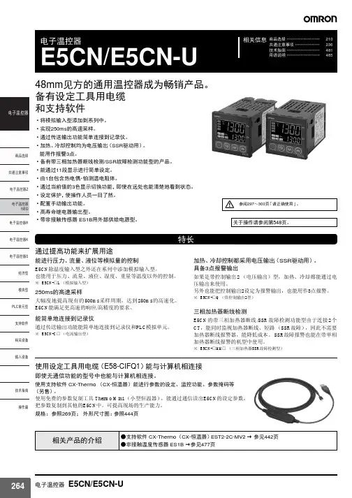
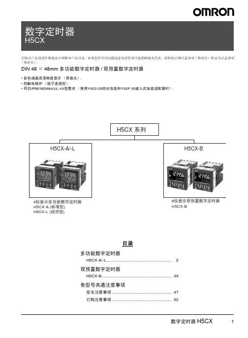
商品选择 ........................210共通注意事项 ..................236技术指南 ........................481用语说明 (485)相关信息电子温控器E5CN/E5CN-U48mm 见方的通用温控器成为畅销产品。
备有设定工具用电缆和支持软件•将模拟输入型添加到系列中。
•实现250ms 的高速采样。
•通过传送输出功能简单连接到记录仪。
•加热、冷却控制均为电压输出(SSR 驱动用)。
能用作报警3点。
•备有带三相加热器断线检测/SSR 故障检测功能型的产品。
•能通过11段显示进行简单设定。
•由1台包含热电偶·铂测温电阻体。
•通过当前值的3色显示切换功能,即使在远处也能清楚地看到状态。
•设定保护,使操作人员一目了然。
•配置手动输出功能。
•高寿命继电器输出型。
•带非接触传感器 ES1B 用外部供给电源型。
特长通过提高功能来扩展用途能进行压力、流量、液位等模拟量的控制E5CN 除温度输入型之外还在系列中添加模拟输入型。
也能用于压力、流量、液位、湿度、重量等温度以外的控制。
※E5CN-□L (模拟输入型)250ms 的高速采样大幅度地提高现有的500ms 采样周期,达到250ms 的高速化。
E5CN 能满足更高速的响应/高精度的要求。
能简单地连接到记录仪通过传送输出功能能简单地连接到记录仪和PLC 模拟单元。
※E5CN-C □(电流输出型)加热、冷却控制都采用电压输出(SSR 驱动用)。
具备3点报警输出如果是带控制输出2(电压输出)型,加热、冷却都能通过电压输出来使用。
另外也能把控制输出2设定为报警输出,也能用作3点报警。
※E5CN-□Q (带控制输出2型)三相加热器断线检测E5CN 的带三相加热器断线/SSR 故障检测功能型由于连接2个CT ,能同时监视加热器断线、短路(SSR 故障),因此不需要加热器断线报警器,能降低成本。
Joystick SwitchesQuality, reliability, precision Quality, reliability and precision are the hallmarks of our corporate philosophy.They represent concepts and values to which we feel totally committed. At EUCHNER, quality means that all our employees take personal respon-sibility for the company as a whole and, in particular, for their own field of work. This individual commitment to perfection results in products which are ideally tailored to the customers’needs and the requirements of the market. After all: our customers and their needs are the focus of all our efforts. Through efficient and effective use of resources, the promotion of personal initiative and courage in find-ing unusual solutions to the benefit of our customers, we ensure a high level of customer satisfaction. We familiar-ize ourselves with their needs, require-ments and products and we learn from the experiences of our cus-tomers’ own customers.EUCHNER – More than safety.Quality –made by EUCHNERMore than safety.Around the world –the Swabian specialists in motion sequence control for mechanical and sys-tems engineering.EUCHNER’s history began in 1940 with the establishment of an engineering office by Emil Euchner. Since that time, EUCHNER has been involved in the design and development of switch-gear for controlling a wide variety of motion sequences in mechanical and systems engineering. In 1953, Emil Euchner founded EUCHNER +Co., a milestone in the company’s history. In 1952, he developed the first multiple limit switch –to this day a symbol of the enterprising spirit of this family-owned company.Automation –Safety –ManMachine Today, our products range from electromechanical and electronic components to complex system solu-tions. With this wide range of products we can provide the necessary tech-nologies to offer the right solution for special requirements – regardless of whether these relate to reliable and precise positioning or to components and systems for safety engineering in the automation sector.EUCHNER products are sold through a world-wide sales network of compe-tent partners. With our closeness to the customer and the guarantee of reliable solutions throughout the globe, we enjoy the confidence of cus-tomers all over the world.Emil Euchner, the company’s founder and inventor of the multiple limit switch, circa 1928.ManMachineTable of contents Joystick switchesDesign and function4Advantages/features4Series5Series WK...Control panel installation to IEC 947-5-1 D306Series WE...Control panel installation at rear or with front plate8Series KB...Control panel installation to IEC 947-5-1 D3010Series KF...Control panel installation at rear12Series KE...Control panel installation to IEC 947-5-1 D2214Series KC...Control panel installation at rear or with front plate16Series KP...Analog JoystickControl panel installation at rear or with front plate19Universal Power Supply Unit P1/P2 for series KP joysticks22Housing HBL23Housing HBE24Front plates for housing HBL and HBE25 Technical status 09-03/06ApplicationJoystick switches or joysticks are manually actuated control devices for installation in control and front panels as well as in portable control equipment. They are used wherever motion sequences analogous to the actuation direction are controlled by hand. They are ideal for raising, lowering and triggering movements to the right and left, just to name same few possibilities.EUCHNER joysticks are used in the steel and construction industry, in machine tools, for transport and conveyor systems, in thecertification, the devices are approved for use in the ship-building industry.EUCHNER joysticks are also used for radio and cable controls, building machinery and cranes.Joysticks as control equipment in remote control devicesDesign and functionMicroswitches with a step function response are used as switching elements. Due to the intermittent control, a clear switching function is given for precise control systems. Depending on the respective application, switching elements with a power rating of between 4mA and 16A can be used. These are fixed on the mounting plate for each different series, either individually or in groups. The switching elements are actuated by the joystick being moved out of the intermediate position. The robust levers made of stainless steel are bedded with a hinged ball bearing that is fixed in a front plate.Advantages/featuresDirection of movement: Simplification of the command control station Easy mounting due to the slots in the panel Small space requirement Long service lifeRobust and lasting constructionHigh potection class: IP 65 and beyondRemote cable control for concrete pumpsModelsEUCHNER joystick switches are available in a number of different models:Series WK...(page 6)Series WE...(page 8)Series KB...(page 10)Series KF ...(page 12)Series KE...(page 14)Series KC...(page 16)Series KP...(page 19)Housing kits (from page 22)suitable for series WK, KB, KE and KFActuatingdirectionsPanel cutoutPushbutton D(with protective cap)Interlock VBellows WClamping screws forpanel thickness (1 - 8 mm)Centre position switch Z (actuated in centre position)Connection D(the connection is located on the under-side for types with 8 directions)Series WK...Control panel installation to IEC 947-5-1 D301 to 8 actuating directions with spring return operation or combinedOne changeover contact with tab connector 2.8 x 0.5 IEC 760 for each actuating direction Centre position switch Pushbutton in handleDimension drawingGermanischer LloydCertificate no. 17 041 - 00 HHOrdering codeSeriesActuating direction and switching behavior Stayput switch S (switching lever latches in selected position)Spring return switch T (switching lever returns to centre position)Options Pushbutton D Bellows W InterlockV Centre position switch Z All-round actuationRW KOrdering examples:Joystick switch series WK, actuating directions 1+3 stayput switch S,WK S13 T24 DZV actuating directions 2+4 spring return switch T, Pushbutton D, centre position switch Z,Interlock V in centre positionJoystick switch series WK, 8 switching elements as spring return switches, all-round actuation R WK T1-8 R DesignJoystick switch series WK, 4 switching elements, 2 actuating directions on request (2 switching elements per actuating direction)* Diagonal actuation of 4 adjacent switching elements is on request.Control panel installation and actuating directionsFront platePushbutton D(with protective cap)Interlock VBellows WConnection Series WE...Control panel installation at rear or with front plate1 to 8 actuating directions with stayput or spring return operation or combined One changeover contact with screw terminal for each actuating direction Centre position switch Pushbutton in handleDimension drawingGermanischer LloydCertificate no. 17 041 - 00 HHOrdering codeSeriesActuating direction and switching behavior Stayput switch S (switching lever latches in selected position)Spring return switch T (switching lever returns to centre position)Options Pushbutton D Bellows W InterlockV Centre position switch Z All-round actuation R Front plate FW EFront plate FOrdering examples:Joystick switch series WE, actuating directions 1+3 stayput switch S,WE S13 T24 DZV actuating directions 2+4 spring return switch T, Pushbutton D, centre position switch Z,Interlock V in centre positionJoystick switch series WE, 8 switching elements as spring return switches, all-round actuation R WE T1-8 R DesignJoystick switch series WE, 4 switching elements, 2 actuating directions on request (2 switching elements per actuating direction)Actuating directionsPanel cutoutInterlock V BellowsSeries KB...Control panel installation to IEC 947-5-1 D301 to 8 actuating directions, 4 switching elements. With stayput or spring return operation or combined One changeover contact with tab connector 6.3 x 0.8 IEC 760 for each actuating directionDimension drawingGermanischer LloydCertificate no. 17 041 - 00 HHOrdering codeSeriesActuating direction and switching behavior Stayput switch S (switching lever latches in selected position)Spring return switch T (switching lever returns to centre position)Options InterlockV All-round actuationR 1)1) Simultaneous actuation of 2 adjacent switching elements in diagonal actuating directions.KBOrdering examples:Joystick switch series KB, actuating directions 1+3 stayput switch S,KB S13 T24 actuating directions 2+4 spring return switch TJoystick switch series KB, actuating directions 1+3 spring return switch T,KB T13 V Interlock V in centre positionSeries KF ...Control panel installation at rear1 to 8 actuating directions, 4 switching elements. With stayput or spring return operation or combined One changeover contact with screw terminal for each actuating direction Centre position switchDimension drawingGermanischer LloydCertificate no. 17 041 - 00 HHOrdering codeSeriesActuating direction and switching behavior Stayput switch S (switching lever latches in selected position)Spring return switch T (switching lever returns to centre position)OptionsCentre position switch Z All-round actuation R 1)1) Simultaneous actuation of 2 adjacent switching elements in diagonal actuating directions.KFActuating directionsPanel cutoutOrdering examples:Joystick switch series KF, actuating directions 1+3 stayput switch S,KF S13 T24 Z actuating directions 2+4 spring return switch T, centre position switch ZJoystick switch series KF, actuating directions 1-4 spring return switch T,KF T1234 R all-round actuation RActuating directionsPanel cutoutInterlock VBellowsCentre position switch Z (actuated in centre position)Series KE...Control panel installation to IEC 947-5-1 D221 to 8 actuating directions, 4 switching elements. With stayput or spring return operation or combined One changeover contact with tab connector 2.8 x 0.5 IEC 760 for each actuating direction Centre position switchDimension drawingGermanischer LloydCertificate no. 17 041 - 00 HHOrdering codeSeriesActuating direction and switching behavior Stayput switch S (switching lever latches in selected position)Spring return switch T (switching lever returns to centre position)Options InterlockV Centre position switch Z All-round actuation R 1)1) Simultaneous actuation of 2 adjacent switching elements in diagonal actuating directions.KEOrdering examples:Joystick switch series KE, actuating directions 1+3 stayput switch S,KE S13 T24 Z actuating directions 2+4 spring return switch T, centre position switch ZJoystick switch series KE, actuating directions 1+3 spring return switch T,KE T13 V Interlock V in centre positionJoystick switch series KE, actuating directions 1-4 Spring return switch T,KE T1234 R all-round actuation RActuating directions Top view of actuating leverCentre position switch Z (actuated in centre position)Series KC...control panel installation at rear or with front plate1 to 8 actuating directions with 1 or2 switching positions for each actuating direction Switching positions as stayput or spring return operation in various combinationsCentre position switch Pushbutton in handleDimensiondrawingMain actuating directions1, 2, 3 and 4Diagonal actuating directions5, 6, 7 and 8Switching position ISwitching position IID V1)Panel cutout for assembly with bellows WX Germanischer LloydCertificate no. 17 041 - 00 HHOrdering examples: (see type code on page 18)Joystick switch series KC with tab connector, main actuating direction KCA3A5C005C0000V1 1 with 3 switching elements. As spring return switch in switching position I.As stayput switch in switching position II.Main actuating directions 2 and 4 with 2 switching elements each. As stayput switch in switchingpositions I and II. Main actuating direction 3 not used. Option V1 (mech. inter-lock from switching position I to switching position II)Joystick switch series KC with screw terminal, main actuating directions 1-4KCB4E4E4E4E5678DW as stayput switch. S with one switching element each, diagonal actuating directions 5-8,Pushbutton D, bellows W for panel mounting.Ordering codeSeriesConnection typeTab connector 2.8 x 0.5 IEC 760A Screw terminalBMain actuating direction 1Switching behavior 1)Switching function 2)Main actuating direction 2Switching behavior 1)Switching function 2)Main actuating direction 3Switching behavior 1)Switching function 2)Main actuating direction 4Switching behavior 1)Switching function 2)Diagonal actuating direction 5 3)Diagonal actuating direction 6 3)Diagonal actuating direction 7 3)Diagonal actuating direction 8 3)OptionsPushbutton in handleD Bellows for panel mounting W Bellows for surface mounting X Interlock switching position 0V0Interlock switching position I to II V1Centre position switch Z All-round actuationR1) See …Switching behavior “ table. Actuating directions which are not required must be marked with …0“.2) See …Switching functions “ table.3) Simultaneous actuation of 2 adjacent switching elements in diagonal actuating directions.K CSeries KC...Switching behavior 1)G Stayput switch (switching lever latches in selected position)Spring return switch (switching lever returns to initial position)Switching functions 2)1-23G 4G -5G G 6G I II0I II11A2F23311B 2G2311C 2H2331D 2K2331E2331Contact state in switching positionControl versionsCentre position switch Z (actuated in centre position)Series KP ...Analog Joystickcontrol panel installation at rear or with front plate Analog, proportional output signalsControl variants with 1 and 2 axes or 2 axes simultaneously Centre position switch Pushbutton in handleDimension drawing3D V1)Panel cutout for assembly with bellows WX Versions 1 = 1 axis Versions 2 = 2 axesVersions 3 = 2 axes simultaneously (only spring return version)Ordering codeSeriesControl variants 1 axis 12 axes22 axes simultaneously 3End position Stayput switchS Spring return switch TOptions PushbuttonD Bellows for panel mounting W Bellows for surface mounting X InterlockV Centre position switchZK PSeries KP ...Analog JoystickPin assignment-X (-Y)+X (+Y)+10V-10VConnection Centre position switchConnection PushbuttonInputOutput Y ± 10 V, 10 mA 0 V 0 V (GND)X± 10 V, 10 mA- V -18 V 0 V 0 V (GND)+ V+18 VOrdering example:Analog Joystick series KP for 2-axis control, limit position spring return switch T ,KP 2 TVWZmechanical interlock, V in zero position, bellows W for panel mounting,centre position switch Z in switching position zeroUniversal Power Suply Unit P1/P2 Order No. 096 645∅DTechnical dataOrdering tablePG 11073 098for heavy gauge cable gland PG 11, 6 screws for front plate attachment, cover frame PG 13.5Housing HBL, with magnetic clamp, hanging clip, fixing nut072 630for heavy gauge cable gland PG 13.5, 6 screws for front plate attachment, cover frameNote2 versions for different cable glandsPG 1119PG 13.520.8Hanging clipView AAMagnetic clampScrew depth max. 6.0 mm (valid for all fixing holes)Dimension drawing∅DTechnical dataOrdering tablePG 11048 429 for heavy gauge cable gland PG 11, 4 screws for front plate attachmentPG 13.5Housing HBE, with magnetic clamp, hanging clip, fixing nut072 626 for heavy gauge cable gland PG 13.5, 4 screws for front plate attachmentDimension drawingNotes2 versions for different cable glands View A AHanging clipMagneticclampPG 1119PG 13.520.8Technical dataOrdering tableFront plate for HBL housing, with seal 055 967Front plate for HBE housing, with seal052 954Front plates for housing HBL and HBE Front plates HBLFront plateFlat sealDimension drawingFront plates HBEFront plateFlat seal。
1MC-510目录快速测量方法 (2)安全注意事项 (3)商品构成 (6)体温的基本常识 (8)测量方法 (9)电池更换方法 (17)有疑问时 (18)显示出错时 ................20保养与保管 ................22规格 ..........................23咨询 .. (24)产品保证书 (25)保修卡 .......................26非常感谢您购买欧姆龙速测体温宝,为了正确使 ⏹用本产品,请务必在使用之前阅读本产品说明书。
为了安全正确地使用本产品,请阅读并充分理解 ⏹本说明书中的“安全注意事项”。
敬请经常把说明书放在身边以便查阅。
⏹本说明书兼作产品质量保证书,故请妥善保管勿 ⏹丢失。
快速测量方法3说明书中所表示的警告记号和警告图例,其目的 ⏹是为了使您能够安全、正确地使用本产品,并防止对您及他人造成伤害。
警告记号、图例及其含义如下:⏹※ 所谓物品损坏是指有关房屋、家产及家畜、宠物的损害。
安全注意事项45建议• 当您把所测体温告诉医生时,请说明您是用耳式体温计进行测量的。
• 请不要用于人体耳部以外的体温测量。
• 请不要强行碰撞、摔落、踩踏和摇动本体。
•请勿在测量过程中在体温计附近使用移动电话。
• 请勿拆卸、修理和改造本体。
• 本产品不防水。
请注意不要让液体(酒精、水滴、热水等)进入本体内部。
6☆ 探测器保护罩是消耗品,使用完结后请购买新的探测器保护罩。
☆ 探测器保护罩脏污破损时,请更换探测器保护罩,因为表面的脏污和破损会影响测量精度。
78体温的基本常识测量腋下和舌下的体温易受外界温度、汗水和唾液等的影响,所以较之所测的温度偏低,而测量耳温可更好地反映脑部温度,快速测得正确的体温值。
为了正确判断发烧的状态,请了解正常情况下家庭成员的耳温。
耳温和腋下温度分布了解家庭成员正常状态时耳温。
耳温与腋下温度存在差异,通过正常状态时耳部与腋下的「温度差」可以大致比较出发烧时的「温度差」。