上海800kv特高压直流输电系统设计
- 格式:pdf
- 大小:267.60 KB
- 文档页数:5


Converter Valve Design and Valve Testing for Xiangjiaba – Shanghai ±800kV 6400MW
UHVDC Power Transmission Project
Baoliang Sheng,Jonatan Danielsson, Yanny Fu and Zehong Liu
Abstract — Thyristor valve design merits are inherited and new developed high power rating thyristors are used in the valve design. The thyristor control unit (TCU) and snubber circuit are optimized for a high reliability and low loss of thyristor valves. Two 12-pulse converters are connected in series as one converter per pole. The converters use a double valve MVU structure.
A careful designed rigorous type test program has been followed to verify the valve and converter design. A single valve
is comprehensively dielectric type tested and operational type tested. High voltage valve hanging structure, low voltage valve hanging structure and MVU, plus the series connected valve simulator, are valve supporting structure dielectric tested and MVU dielectric tested. The test results indict that the valve voltage and converter design and protection are proper and there
is a substantial margin in operation since, for most of the operational tests, the test parameters were globally more severe than specified.
Index Terms ⎯Xiangjiaba – Shanghai ±800kV UHVDC, HVDC converter, thyristor valve design, thyristor valve dielectric test, thyristor valve operational test
I.I NTRODUCTION
BB was granted to design and manufacture the converters
used in the inverter station, Fengxia substation, for the
first ±800kV 6400MW bulk power transmission project. Converter in this project comprises of two 12-pulse thyristor valves in series connection per pole. Those two 12-pulse thyristor valves are installed in a low voltage (0 – 400kV d.c.) valve hall and a high voltage (400kV – 800kV d.c.) valve hall respectively to build up the 800kV pole d.c. voltage.
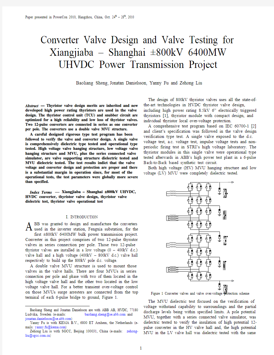
A double valve MVU structure is used to mount those valves in the valve halls. There are four MVUs in series connection per pole and phase with two of them located in the high voltage valve hall and the other two located in the low voltage valve hall. For a better transient over-voltage control on those MVUs surge arresters are connected from the top terminal of each 6-pulse bridge to ground, Figure 1.
Baoliang Sheng and Jonatan Danielsson are with ABB AB, HVDC, 77180 Ludvika, Sweden (e-mails: baoliang.sheng@ and jonatan.danielsson@)
Yanny Fu is with KEMA B.V., 6800 ET Arnhem, the Netherlands (e-mails: yanny.fu@)
Zehong Liu is with SGCC, Beijing 100031, China (e-mails: zehong-
liu@) The design of 800kV thyristor valves uses all the state-of-
the-art technologies in HVDC thyristor valve design,
including high power rating 8.5kV 6” electrically triggered
thyristors [1], thyristor module with compact design, and
individual thyristor local over-voltage protection.
A comprehensive test program based on IEC 60700-1 [2]
and client’s specification was followed in the valve design
verification type test. A single valve exposed to the d.c.
voltage test, a.c. voltage test, impulse voltage tests and non-
periodic firing test in STRI’s high voltage laboratory. The
thyristor modules in this single valve were operational type
tested afterwards in ABB’s high power test plant in a 6-pulse
Back-to-Back based synthetic test circuit.
Both high voltage (HV) MVU hanging structure and low
voltage (LV) MVU were completely dielectric tested.
Figure 1 Converter valves and valve over-voltage protection scheme
The MVU dielectric test focused on the verification of
voltage withstand capability to surroundings and the partial
discharge levels being within specified limits. A pole potential
MVU, together with a series connected valve simulator, was
dielectric tested to verify the insulation of high potential 12-
pulse converter in the HV valve hall and, the high potential
MVU in the LV valve hall was dielectric tested with the same A