FR A AP使用手册
- 格式:pdf
- 大小:1015.57 KB
- 文档页数:42
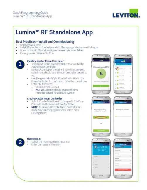
Quick Programming Guide Lumina™ RF Standalone AppEnroll Devices • Familiarize yourself with the Main Configuration screen • Topics should be addressed from top to bottom • Select “Devices” to enroll/add devices to the system Add Devices • Select “Start Enrollment” to scan for Room Controllers, Load Control Devices, and additional peripheral devices and lamps • As devices are found, they will be added to the list and the Found Devices counter will increase • Some lamps and load controllers dim when enrolled to the network • Stop enrollment should be pressed when all devices are found—enrollment ends at 2 minutes Verify Devices • NOTE: Verify that all devices have been enrolled/added to the system before moving on to Step 5• Select the “Identify” button and uncheck devices that should not be part of the room Create Groups • Groups are the way the user interacts with the system and represent a collection of lamps and load control devices will dim or turn OFF and ON to indicate enrollment was successful • Common groups:• Front of room • Back of room • Side lights • Buffet lights • White board light • Entry way • Closet • Corridor • Select “Groups” to create groups Group Programming • Select “Add Group” button • Give the Group a name • Use the green Identify buttons to determine which devices to include • Check the box(es) to include the device in the Group • Click “Save” when done • Use the Group Identify button to visually confirm the correct devices were added tothe Group Toggle between Control and Configuration ModeMain ConfigurationTopicsBack to Search forRoom Controller ScreenRoom SettingsApp Menu 2Create Scenes• Scene is a collection of Groups with a fade time andpredetermined level for assignment to a Keypad buttonor recall from the control screen:• Presentation• Movie• Lunch• Meeting• Cleaning• Test taking• Select “Scenes” to create scenesScene Programming• Select “Add Scene”• Give Scene a meaningful name• Set Fade Duration or fade time, 2-5 seconds is common• Select Groups to include• Set desired Target Levels for each Group selected• Hit Save• NOTE: Saves could fail if not all devices in all Groups arecontacted; try again if it failsProgram Keypad(s)• Multiple Room Controllers may coexist in the same space—• The first Room Controller you identified in Step 1 is the“Master Room Controller”• Other Room Controllers will be “Remotes” and are addedusing the Devices screen• Select “Keypads” and select the Keypad you want toconfigureKeypad Programming• Select the gear icon on the Keypad button you want toconfigure, then assign the action and any other necessaryparameters• On/Off—impacts entire room• Toggle Room—turns the room on/off from the samebutton• Toggle Group—turns a Group on/off from the samebutton• Scene—executes a scene• Raise/Lower Light Levels—affects entire room• Set color—used to configure compatible RGB lamps• Color temperature—used to configure lamps withadjustable color temperature3Configure Room Settings • Room settings impact the entire room instead of a single device • Select the “Room Settings” gear icon • Occupancy Sensor Settings • Use the slider to enable/disable occupancy sensor capabilities • General > Sensitivity indicates how sensor responds • Mode determines lighting behavior • Primary/Secondary Timeouts available • Daylighting Settings • Use the slider to enable/disable daylight harvesting capabilities • Cap Target —lights always return to target • Override Allowed —user can set lights to any level until the override time elapses • Target Mode —auto or manual • Set Pin —allows user to change pin • Your phone may require you to “Forget Device” andreconnect on changeG-10474B/B20-cdsREV FEB 2020Leviton Manufacturing Co., Inc. Lighting & Controls20497 SW Teton Avenue, Tualatin, OR 97062 tel 800-736-6682 fax 504-404-5594 tech line (6:00AM-4:00PM PT Monday-Friday) 800-954-6004 Leviton Manufacturing Co., Inc. Global Headquarters201 North Service Road, Melville, NY 11747-3138 tel 800-323-8920 fax 800-832-9538 tech line (8:30AM-7:00PM ET Monday-Friday) 800-824-3005 Visit our website at: /luminarf© 2020 Leviton Manufacturing Co. Inc. All rights reserved. Subject to change without notice.4。
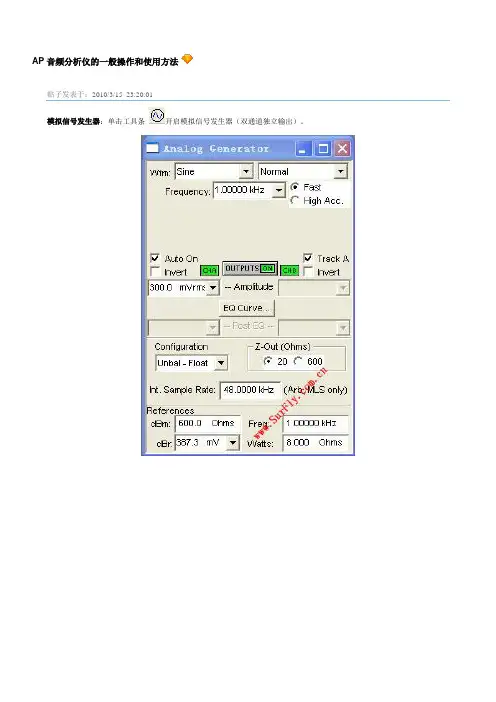
AP音频分析仪的一般操作和使用方法贴子发表于:2010/3/15 23:20:01模拟信号发生器:单击工具条开启模拟信号发生器(双通道独立输出)。
•Wfm: 选择产生信号波形。
一般测量使用Sine / Normal(典型正弦波波形),是由模拟部分硬件产生的低失真度的信号,20Hz –20KHz时失真度< 0.0001%。
•Frequency: 设定信号频率,Sine / Normal模式下可设定频率范围:10Hz –204KHz。
输入时可加单位“k(千)”。
•Fast / High Acc.: 选择快速(+/-0.5%)或高精度(+/-0.03%)模式。
快速模式适合于一般音频测试,建议在需高速自动测试中使用。
高精度模式产生精确的信号频率,但需150mS –750mS的设定反应时间,建议手动测试时选用此模式提高测量精度。
•Amplitude: 设定信号振幅。
平衡输出时可设定振幅:<10uV –13.33Vrms。
非平衡输出时可设定振幅:<10uV –26.66Vrms。
输入时可加单位“n(纳),u(微),m(毫)”。
注意因信号发生器的输出阻抗的差异,和DUT输入阻抗的差异,会导致DUT输入端的信号电压偏低于APWIN的设定电压。
•OUTPUT ON/OFF: 信号发生器输出开关。
按钮绿色是开启,灰色是关闭。
•Auto On: 如选中,在扫频开始时自动开启信号发生器,结束时自动关闭信号发生器。
•CHA On/Off: A通道输出开关。
按钮绿色是开启,灰色是关闭。
作用在信号发生器输出开关前。
•CHB On/Off: B通道输出开关。
按钮绿色是开启,灰色是关闭。
作用在信号发生器输出开关前。
•Invert: 信号相位180度反转。
可分别控制A / B通道。
通常反转B通道相位用于Dolby ProLogic测量。
•Track A: 如选中则同时设定A / B通道的振幅,反之分别设定。
•EQ Curve: 选用APWIN或自定的均衡器曲线。
ALCOR量产工具操作手册2012.11.22目录1.运行环境 (1)2.主要功能 (1)2.1FLASH支持部分 (1)2.2U盘制作功能 (1)3.快速使用方法 (2)4.设定界面详细说明 (3)4.1主界面 (3)4.2密码设定 (4)4.3存储器设定 (5)4.3.1存储器类别 (5)4.3.2鼠产设定 (5)4.4装置方式设定 (8)4.4.1普通盘 (8)4.4.2本地盘 (9)4.4.3只读盘 (9)4.4.4加密盘 (10)4.4.5AES 盘 (10)4.4.6AutoRun 盘 (10)4.5 U盘信息设定 (12)4.6坏磁区设定 (13)4.7其它设定 (15)4.8界而显示 (16)4.9导出配置和导入配置 (17)5.MP错误代码对照表 (18)6.常见错误详解 (21)1.运行环境适用J - Wmdows XP, Wui7,Win8。
该软件是绿色版的,不用安装即可以使用。
2.主要功能2.1 FLASH支持部分1)最多可以16个U盘同时虽产。
2)支持不同型号的FLASH同时吊产,并可单独停止或开始任意一颗的吊:产。
3)自动识别FLASH型号、ID、CE数目,也可手动选择FLASH型号进行昂产。
4)支持单贴、双贴、单通道和双通道。
5)''低格检测、'设定,可■支持Half Page及其它特殊状况的FLASH,6)提供手动选择ECC设定。
7)有高级格式化和低级格式化两种扫描方式:a.高级格式化指扫描时直接读取FLASH的坏块信息,分为全新、全新+AA55、量产过和清空四个扫描级别:全新:直接读取原厂坏块信息。
全新+AA55:全新扫描+简单的检测。
量产过:直接读取上一次量产写入的坏块信息(必须是该量产I.具呐产过)。
清空:将FLASH存储的信息全部清空。
b.低级格式化指扫描时写数据到FLASH再读出来比较以确定坏块,扫描级别分两大类:全面扫描:对FLASH的所有位置进行检测。

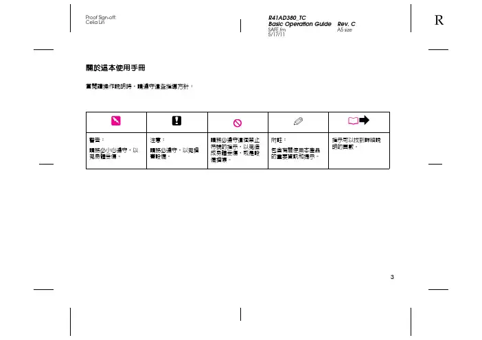
5/17/11關於這本使用手冊當閱讀操作說明時,請遵守這些指導方針:w c Q R&警告:請務必小心遵守,以免身體受傷。
注意:請務必遵守,以免損害設備。
請務必遵守這個禁止符號的指示,以免造成身體受傷,或是設備損壞。
附註:包含有關使用本產品的重要資訊和提示。
指示可以找到詳細說明的頁數。
3版權注意事項No part of this publication may be reproduced, stored in a retrieval system, or transmitted in any form or by any means, electronic, mechanical, photocopying, recording, or otherwise, without the prior written permission of Seiko Epson Corporation. The information contained herein is designed only for use with this product. Epson is not responsible for any use of this information as applied to other printers.Neither Seiko Epson Corporation nor its affiliates shall be liable to the purchaser of this product or third parties for damages, losses, costs, or expenses incurred by the purchaser or third parties as a result of accident, misuse, or abuse of this product or unauthorized modifications, repairs, or alterations to this product, or (excluding the U.S.) failure to strictly comply with Seiko Epson Corporation掇 operating and maintenance instructions.Seiko Epson Corporation shall not be liable for any damages or problems arising from the use of any options or any consumable products other than those designated as Original Epson Products or Epson Approved Products by Seiko Epson Corporation.Seiko Epson Corporation shall not be held liable for any damage resulting from electromagnetic interference that occurs from the use of any interface cables other than those designated as Epson Approved Products by Seiko Epson Corporation.EPSON® is a registered trademark, and Exceed Your Vision and EPSON ME are trademarks of Seiko Epson Corporation.PRINT Image Matching™ and the PRINT Image Matching logo are trademarks of Seiko Epson Corporation. Copyright © 2001 Seiko Epson Corporation. All rights reserved. SDHC™ is a trademark.Memory Stick, Memory Stick Duo, Memory Stick PRO, Memory Stick PRO Duo, Memory Stick PRO-HG Duo, Memory Stick Micro, MagicGate Memory Stick, and MagicGate Memory Stick Duo are trademarks of Sony Corporation.xD-Picture Card™ is a trademark of Fuji Photo Film Co., Ltd.General Notice: Other product names used herein are for identification purposes only and may be trademarks of their respective owners. Epson disclaims any and all rights in those marks.45/17/11重要的安全說明565/17/11保護您的個人資料本產品可讓您將名字和電話號碼儲存在產品的記憶體中,即使關閉若您要將本產品轉送他人或是丟棄,請使用下列選單,清除記憶體中的資料。

ARJ21-700用于机场计划的飞机特性手册ACAP编号:TP700051(PMC:ARJ21-SVV19-50009-00)初版版:2014.10.31R9:2022.12.29有 意 留 白本技术出版物的使用者,对于本出版物的使用、披露、管理等行为,需遵循中国商用飞机有限责任公司(“中国商飞”)技术出版物适用的任一国家/地区出口管制和经济制裁相关法律法规。
中国商用飞机有限责任公司专有信息、保密信息和/或商业秘密版权©2022中国商用飞机有限责任公司版权所有声明中国商用飞机有限责任公司对本文件及其每页的版权声明仅限于该页面所包含的受版权保护的内容。
同时,中国商用飞机有限责任公司声明该文件享有作为汇编和/或集合作品的版权。
本文件含有中国商用飞机有限责任公司的专有信息。
未经中国商用飞机有限责任公司事先书面授权,不可基于任何目的将本文件所含信息的全部或部分内容进行直接或间接的复制、引用、披露或使用。
如果取得全部或部分复制本文件的书面授权,应当将本声明完整地加入所有复制文本中。
非授权接收人应立即告知中国商用飞机有限责任公司并退回本文件及任何复制文本。
“中国商飞”、“COMAC”、“ARJ21”、“C919”及包含“中国商飞”、“COMAC”、“ARJ21”、“C919”字样的图标为中国商用飞机有限责任公司持有商标。
未经中国商用飞机有限责任公司书面同意,任何与本文件相关的商标许可(不论是明示或暗示)均未获得授予。
有 意 留 白—发送函2022.12.29发给:技术出版物的持有者。
本更改适用于用于机场计划的飞机特性手册。
更改说明对于纸质技术出版物,应按照有效数据模块清单进行换页或插页。
在有效数据模块清单中,更改、新增、删除和恢复数据模块分别用C、N、D和RR表示。
被更改和删除的数据模块必须从纸质技术出版物中撤出并销毁。
对于电子手册,本版本应替代上一版本的所有内容。
如果收到纸质技术出版物的更改,必须确认已经收到并归档本次更改之前的技术出版物更改。
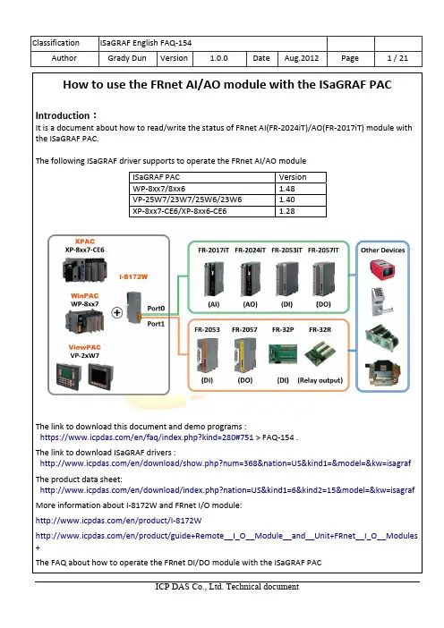
How to use the FRnet AI/AO module with the ISaGRAF PACIntroduction :It is a document about how to read/write the status of FRnet AI(FR‐2024iT)/AO(FR‐2017iT) module with the ISaGRAF PAC.The following ISaGRAF driver supports to operate the FRnet AI/AO moduleThe link to download this document and demo programs :https:///en/faq/index.php?kind=280#751 > FAQ‐154 .The link to download ISaGRAF drivers :/en/download/show.php?num=368&nation=US&kind1=&model=&kw=isagraf The product data sheet:/en/download/index.php?nation=US&kind1=6&kind2=15&model=&kw=isagraf More information about I‐8172W and FRnet I/O module: /en/product/I‐8172W/en/product/guide+Remote__I_O__Module__and__Unit+FRnet__I_O__Modules +The FAQ about how to operate the FRnet DI/DO module with the ISaGRAF PACISaGRAF PAC VersionWP‐8xx7/8xx6 1.48VP‐25W7/23W7/25W6/23W6 1.40XP‐8xx7‐CE6/XP‐8xx6‐CE6 1.28Restore the demo project “faq154.pia” :1342123 45 61.2. Introduction of FR‐2017iT:●Hardware description:The FR‐2017iT is a 16‐bit (1 channel) and 12‐bit (8‐channel differential or 16‐channel single‐ended) analog inputs module that provides two ways to select input range (+/‐150mV, +/‐500mV, +/‐1V, +/‐5V, +/‐10V, +/‐20mA, 0~20mA and 4~20mA).The refresh rate by each channel status is different, due to the channel mode of the FRnet module.The refresh rate of one channel mode is 100ms/time. The refresh rate of 8 channel mode is250ms/time. The refresh rate of 16 channel mode is 500ms/time. But the refresh rate is notchanged when add more and more modules to the FRnet bus.More detail description about FR‐2017iT, please refer to the following website:/en/product/FR‐2017iT●Hardware setting:●SW1 : The SW1 can be used to configure the module to 8‐ch differential/16‐ch single‐ended,12/16‐bit resolution and individual/all Channel mode.Pin1 Pin2 Pin3 Type code: 000~111, for +/‐500mV, +/‐1V, +/‐5V, +/‐10V+/‐20mA (requires optional external 125ohm resistor)Pin4 SE/DF ON→16 Single‐endedOFF→8 DifferentialPin5 Resolution ON→16‐bitOFF→12‐bitPin6 Configuration ON→Software SelectableOFF→Switch SelectableType SW1 Min Max1 2 30 ~ 20mA ON ON ON 000 (0mA) FFF (20mA)4 ~ 20mA OFF ON ON 000 (4mA) FFF (20mA)+/‐10V ON OFF ON 800 (‐10V) 7FF (+10V)+/‐5V OFF OFF ON 800 (‐5V) 7FF (+5V)+/‐1V ON ON OFF 800 (‐1V) 7FF (+1V)+/‐500mV OFF ON OFF 800 (‐500mV) 7FF (+500mV)+/‐150mV ON OFF OFF 800 (‐150mV) 7FF (+150mV)+/‐20mA OFF OFF OFF 800 (‐20mA) 7FF (+20mA)Dip switch: The dip switch can be used to configure the module address and the speed of FRnet bus.Wire connection:The wiring of 8‐ch differential analog inputs The wiring of 16‐ch single‐ended analog inputsHardware setting:The SW3 can be used to configure the output type or enable/disable the safe value mode.Type code: 000~111, for 0~20mA, 4~20mA, 0~5V, +/‐5V, 0~10V, +/‐10VTypeSW3Min Max 1 2 30 ~ 20mA ON ON ON 000 (0mA) FFF (20mA)4 ~ 20mA OFF ON ON 000 (4mA) FFF (20mA)0V ~ +10V ON OFF ON 000 (0V) FFF (+10V)‐10V~+10V OFF OFF ON 800 (‐10V) 7FF (+10V)0V ~ +5V ON ON OFF000 (0V) FFF (+5V)‐5V ~ +5V OFF ON OFF800 (‐5V) 7FF (+5V) Dip Switch : The dip switch can be used to configure the module address and the speed of FRnet bus.LED MappingPWR Power LEDRUN Communication Run LEDERR Communication Error LEDEND Terminal resistor OnSW2 SwitchInt.pwr Internal PowerExt.pwr External PowerDIP SwitchPin1 Module Address:0~7Pin2Pin3Pin4 ReservedPin5 ReservedPin6 ReservedPin7 Speed:ON → 250k bpsOFF→ 1M bpsPin8 ReservedCOM0Each analog channel is allowed toconfigure an individual range by CA‐0904cable.Wire connection:SW2: it can be use to set the module using internal or external power.The connection of internal power: The connection of external power:1.4. The description of C‐function block “fr_16ai”:●Parameter:Name Type descriptionSlot_ integer The slot which plugged the I‐8172W related to the FRnet AI.WP‐8xx7: max. 8 pcs. of I‐8172W; can be slot 0~7VP‐25W7/23W7: max. 3 pcs.; can be slot 0~2XPAC‐8xx7: max. 7 pcs.; can be slot 1~7Port_ integer The I‐8172W port that link to the FRnet AI (0 or 1 )Addr_ integer Module address. AI module: 8 ~ 15Type_ integer Set up the output type:16#00 : ‐15mV→+15mV ( Val is ‐32768 to 32767 )16#01 : ‐50mV→+50mV ( Val is ‐32768 to 32767 )16#02 : ‐100mV→+100mV ( Val is ‐32768 to 32767 )16#03 : ‐500mV→+500mV ( Val is ‐32768 to 32767 )16#04 : ‐1V → +1V ( Val is ‐32768 to 32767 )16#05 : ‐2.5V → +2.5V ( Val is ‐32768 to 32767 )16#06 : ‐20mA → 20mA ( Val is ‐32768 to 32767 ),with 125 ohm16#07 : 4mA → 20mA ( Val is 0 to 32767 ), with 125 ohm16#08 : ‐10V → 10V (Val is ‐32768 to 32767 )16#09 : ‐5V → 5V (Val is ‐32768 to 32767 )16#0A : ‐1V → 1V (Val is ‐32768 to 32767 )16#0B : ‐500mV → 500mV (Val is ‐32768 to 32767 )16#0C : ‐150mV → 150mV (Val is ‐32768 to 32767 )16#0D : ‐20mA → 20mA (Val is ‐32768 to 32767 )16#1A : 0mA → 20mA ( Val is 0 to 32767 ), with 125 ohm IN1_~IN16_ integer The related variable names of the 16 AI channels.Please declare a "Dump_ai" integer internal variable name andassigned it to those none‐using channels.* Please do not assign the constant to the none‐using channels.●ReturnName Type DescriptionQ_ Boolean Always return True.1.5. The description of C‐function block “fr_8ao”:●Parameter:Name Type DescriptionSlot_ integer The slot which plugged the I‐8172W related to the FRnet AO.WP‐8xx7: max. 8 pcs. of I‐8172W; can be slot 0~7VP‐25W7/23W7 : max. 3 pcs.; can be slot 0~2XPAC‐8xx7: max. 7 pcs.; can be slot 1~7Port_ integer The I‐8172W port that link to the FRnet AO (0 or 1)Addr_ integer Module address. AO module: 0~7Type_ integer Set up the output type:16#30 : 0mA ‐‐‐> 20mA ( Val is 0 to 32767 )16#31 : 4mA ‐‐‐> 20mA ( Val is 0 to 32767 )16#32 : 0V ‐‐‐> 10V ( Val is 0 to 32767 )16#34 : 0V ‐‐‐> 5V ( Val is 0 to 32767 )16#33 : ‐10V ‐‐‐> 10V ( Val is ‐32768 to 32767 )16#35 : ‐5V ‐‐‐> 5V ( Val is ‐32768 to 32767 )Out1_~Out8_ integer The related variable names of the 8 AO channels.Please declare a "Dump_ao" integer internal variable name andassigned it to those none‐using channels.* Please do not assign the constant to the none‐using channels.●ReturnName Type DescriptionQ_ Boolean Always return true●Notice about using FRnet AI/AO module:Fast I/O scan, it is about 3 ms per FRnet I/O scan. But it can be only got one channel status per scan.(This depends on your program’s PLC scan time, for ex, if the ISaGRAF PLC program scan time is about 15 ms, then the scan time for one AI/AO channel will be 15 ms, not 3 ms.)FR‐2017iT/FR‐2024iTSet the bus speed of FR‐2017iT,FR‐2024iT as 1MIn the same bus, the speed of the FRnet modules must be the same. Or the communication between module and module will not work.)FR‐2017iT FR‐2024iTHow to operate the demo project FAQ1541.Recompile the ISaGRAF project and download it into the ISaGRAF PAC. If you are not familiar tothe ISaGRAF software, please refer to “ISaGRAFUser’s manual” Chap.1.1~1.2 and Chap.2. canbe got from the following website./en/download/show.php?num=333&nation=US&kind1=&model=&kw= isagrafer can observe the change of AO_voltage_1~4 and AI_voltage_1~4 from +10V to +10V inthe spy list, just like the figure below.1.7. Description of Demo Program “faq154”● ISaGRAF Project Architecture :This project contains two LD programs(LD1、timer_tr), an ST program(ST1), and two User define C‐function(eng_To_V 、V_To_eng)● The setting of FRnet module in this demo project● ISaGRAF variablesName Type Property DescriptionInit Boolean InternelSet to true at Init, for initializing the FRnet module AI_connection Boolean InternelThe connection status of FRnet AI module AO_1_event Boolean InternelThe event to change the status of AO1 AO_2_event Boolean InternelThe event to change the status of AO2 AO_3_event Boolean InternelThe event to change the status of AO3 AO_4_event Boolean InternelThe event to change the status of AO4 AI_01~AI_04 Integer InternelThe AI status of FR‐2014iT Dump_AI Integer InternelTo connect the none‐using channels of FRnet AI module AO_01~AO_04 Integer InternelThe AO status of FR‐2017iT Dump_AO Integer InternelTo connect the none‐using channels of FRnet AO module AI_voltage_1~4 Real Internel The status of AI channel. The unit is volt .AO_voltage_1~4 Real InternelThe status of AO channel. The unit is volt T1 Timer InternelSet to 500ms at init, for generating the pulseFR‐2017iT FR‐2024iT Address 1 2 Type +‐10V(ON OFF ON) +‐10V(OFF OFF ON) Speed 1M bps 1M bpsAssign the variable“AI_connection” to thesecond channel, forgetting the status of theconnection.The description of “LD1” program:(* Set the variable “INIT” as false in the first scan, *)(* for initializing the FRnet modules. *)(* Please do not use the C function block “Fr_16ai” and “Fr_8ao”(* in the other program. *)(* Do not use the array variable in the C‐function block “FR_8ao” *)(* and “FR_16ai”. *)Attention:Please declare a "Dump_ai" integer internal variable name and assign it to those none‐using channels.Please do not assign the constant to the none‐using channels.Attention:Please declare a "Dump_ao"integer internal variable name and assignit to those none‐using channels.Please do not assign the constant to thenone‐using channels.The description of “timer_tr” program:AO_voltage_1 := AO_voltage_1 + 0.01;if AO_voltage_1 > 10.0 thenAO_voltage_1 := ‐10.0;AO_01 := V_To_eng(AO_voltage_1);(* while getting the trigger event of AO channel2, add 0.05V to it *) (* If its value is over +10V, set it as ‐10V *)if AO_2_event thenAO_voltage_2 := AO_voltage_2 + 0.05;if AO_voltage_2 > 10.0 thenAO_03 := V_To_eng(AO_voltage_3);(* while getting the trigger event of AO channel4, add 0.5V to it *) (* If its value is over +10V, set it as ‐10V *)if AO_4_event thenAO_voltage_4 := AO_voltage_4 + 0.5;if AO_voltage_4 > 10.0 thenAO_voltage_4 := ‐10.0;AO_04 := V_To_eng(AO_voltage_4);Classification ISaGRAF English FAQ‐154 Author Grady Dun Version 1.0.0 Date Aug.2012 Page21 / 21。
ASAP2020使用手册一、准备1. 检查气瓶气瓶压力需保持在0.1-0.15MPa,气瓶出口及仪器接口处均需3天检漏一次。
2. 查看杜瓦瓶中液氮的位置冷阱位置杜瓦瓶在开机状态下始终保持有液氮,若样品测试时间较长,需用小号容器慢慢加入液氮进行补充,使用检测液位的专用工具进行检测,液面要接触到测试杆但不能超过杆上小孔的位置。
二、开机1、开外围设备:泵(包括油泵、干泵,直接插上即可)、电脑、气体。
2、开主机电源(分子泵一般不会关闭无需开启)。
3、听到滴的一声响后可打开应用软件。
三、样品测试文件的建立介孔样品1、建立文件夹(File-Open-Sample Information)File name不可过长,注意文件夹保存的路径。
若没有弹出上述对话框,则打开的是已有的文件。
2、样品文件参数的设置从左至右依次进行即可(1)一般情况下只需更改样品名称即可操作者样品来源样品质量,注意此处的样品质量为样品脱完气后样品的质量,暂时选择默认值即可,待脱气完成后再进行更改。
通过此键可调用已建立好的方法。
(2)主要注意右侧选项等温夹套填充棒样品塞,等温夹套和样品塞为必用,填充棒是在测量比表面积较小的样品时用以减小实体积用的。
(3)升温速率,目标温度,目标温度不宜过高,一般要低于右侧的Hold temp,防止水分蒸发过快,撑坏样品的孔结构,我们一般选用90℃。
此处表示当压力达到7 mmHg时进行快抽,达到500时进行计时,计时40 min后进行加热。
此处温度与时间根据具体样品进行设定,注意不能超过样品所能承受的最高温度,如我们的ZIF-8材料所用条件为120℃,720 min。
(4)插入介孔的测试范围0.05~0.995(吸附过程)之间选取点,0.995~0.05(脱附过程)点数可以由客户需要进行选点。
然后根据需要选择分析选项。
总孔体积选择压力最大0.995处,BET的选点范围为0.05-0.3,BJH的选取分为吸附阶段和脱附阶段均全选,t-plot的选点范围为0.01-06,DFT的选取范围为吸附过程。
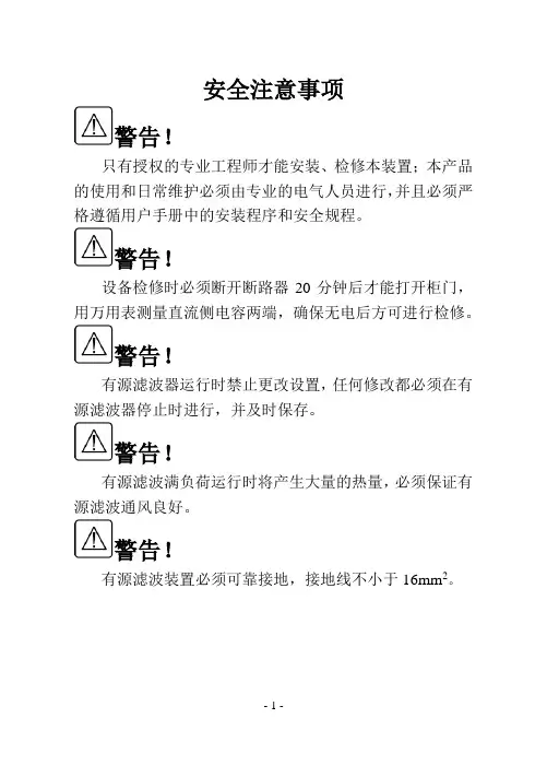
安全注意事项警告!只有授权的专业工程师才能安装、检修本装置;本产品的使用和日常维护必须由专业的电气人员进行,并且必须严格遵循用户手册中的安装程序和安全规程。
警告!设备检修时必须断开断路器20分钟后才能打开柜门,用万用表测量直流侧电容两端,确保无电后方可进行检修。
警告!有源滤波器运行时禁止更改设置,任何修改都必须在有源滤波器停止时进行,并及时保存。
警告!有源滤波满负荷运行时将产生大量的热量,必须保证有源滤波通风良好。
警告!有源滤波装置必须可靠接地,接地线不小于16mm2。
主要技术指标与使用要求目录1 结构简介 .............................................................................. - 4 -1.1主电路原理图 .............................................................. - 4 -1.2外形和主要结构尺寸 .................................................. - 5 -2 安装 (6)2.1机械安装 (6)2.2装置电气安装 (6)2.3 TA电气安装 (8)3 显示面板 (9)3.1主要功能及性能指标 (9)3.2界面说明 (10)4 运行操作 (17)4.1开机前检查 (17)4.2控制板及信号测试 (17)4.3试运行操作 (18)4.4运行操作 (18)5 维护 (20)6 故障处理 (21)6.1维修维护注意事项 (21)6.2故障处理一览表 (22)7 附件 (24)1 结构简介本装置由功率变流器、功率电感、直流侧电容、控制板、显示操作面板、高频滤波电路、电流电压检测电路、机柜等构成。
其结构如图1.1所示。
正视图左视图后视图图1.1有源滤波器结构图1.1主电路原理图主电路由输入保险FU1、FU2、FU3,断路器QF1,功率电感L1、L2、L3、L4、L5、L6,接触器KM1,IGBT及直流侧电容等组成,如图1.2所示。
ALPHA变频器简易操作指南一:键盘应用(1): 键盘布局(2):使用键盘进行参数修改举例二:参数简表………………………………………………………………………………………………………………………三:常用功能块的调试………………………………………………………………………………………………………(1):多段速的应用……………………………………………………………………………………………(2):PLC程序运行应用(3):PID应用经验(4):远程及就地频率切换及运行信号切换的应用(5):模拟量调试经验(6):当使用X1~X8端子时,内部24V电源和外部24电源的用法四:常用案例调试方法及参数指南(1): 恒压供水(供气)(2): 数控车床五: 变频器的应用场合一:键盘应用本系列变频器各规格机型使用不同外形尺寸的键盘,但所以键盘的操作按键和显示的排列都一样,操作方法和相关功能也一样,用户可通过键盘对本机进行功能设定、运行、停车、状态监视等全部操作(1):键盘布局(2):使用键盘进行参数修改举例注意:有的参数可以运行及停机时都能调节,有的需在停机状态下调节(参考说明书功能参数简表○代表运行中及停机时都能更改,X代表只能停机时才能修改)举例1:将P0.21(加速时间)设定为20举例2:将PF.02(参数初始化)设定为2,即恢复出厂值二:参数简表(以下参数为常用参数,如有其它需要请参考说明书)三:常用功能块的调试1:多段速的应用:通过多功能X端子给定频率举例1:通过多功能端子X3给定频率多段速1:30HZ,X4给定多段速2:45HZ, X1端子给定运行指令接线图:注意:以上为常用多段速设定方法,还可以通过组合设定更多的多段速,需选择X端子中3个设定为26(SS1多段速度),27(SS2多段速度),28(SS3多段速度),3个端子同时设置才有效,如少一个端子设置则无效,组合效果图如下:2:PLC程序运行功能应用:用户可设定几个多段速自动运行举例1:自定义3段速,键盘RUN启动,以15HZ正转保持30s,25HZ正转保持40s,40HZ反转保持20s,单循环1模式运行3:PID应用经验PID控制是在工程项目中最为广泛的应用,在一些应用场合,变频器内置PID给予了用户很大的方便。
WPB-5000系列AP操作手册1.设备接口说明设备供电接线方式一:DC12V供电(目前设备接口均被屏蔽)方式二:PoE供电方式(DC 48V)2.安装前准备在开始安装使用设备之前,至少需要具备以下条件:1. 一台安装了10/ 100Base-TX 自适应快速以太网卡的电脑2. 以太网卡的IP 地址与设备在相同的网段(设备默认的IP 地址为192.168.0.228),您可以配置以太网卡的IP 地址为192.168.0.X3. 建议使用Microsoft IE 6.0 或以上版本的浏览器4. 两根用于连接设备与电脑的网线3.配置安装1. 依据下图示意,正确做好设备与电脑间的物理连接。
2. 将电脑以太网卡的IP地址设置为192.168.0.X,保证与设备在相同网段。
打开IE浏览器,在地址栏输入192.168.0.228,页面会出现如下提示。
3. 点击“继续浏览此网站”,进入登陆界面。
系统默认的User Name:admin、Password:password。
4. 登陆后基本信息4.AP的配置注意:1、在进行AP配置时,将RF配置和相关管理项设定好,保存每一步设置;然后进行基本设置项的设定。
待此项设定完毕后,根据提示要求重启设备,设置才能生效!2、PC不管是通过无线方式,还是有线方式接入设备时,PC端所对应的网卡的IP地址必须与设备IP地址在同一网段,这样才能登陆管理界面进行配置。
(以下基于“基本设定”界面介绍AP的两种配置方式——网桥和路由器。
在实际使用过程中根据需要择其一即可。
)A: 网桥的配置1.点击“无线设定”,将其页面的“操作模式”设置为“AP模式”----将“无线模式”设定为“自适应(802.11g和802.11b)”----根据设备安装现场无线勘测的情况,将“信道频率”设定为1、6、11信道中的一种,尽量避免其他信道干扰----输出功率选择“FULL”。
其他项保持默认设置。
点击“确定”,保存该页设置。
用户说明书Manual (V4.080A )南京亚派科技实业有限公司Nanjing APAITEK Science & Technology Co., LTDModual Active Power FilterA-APF 模块化有源电力滤波器操作手册上的提示信息本手册中的安全指示标志定义如下:注意!不按规定操作可能造成设备损坏。
危险!带电,可能造成人员伤亡。
危险! 不按规定操作可能造成人员伤害。
注意!有用信息。
目 录Contents第一章 安全说明及标准 (1)1.1 安全须知 (1)1.2 使用范围 (2)第二章 环境条件 (4)2.1 运输环境 (4)2.2 安装环境 (4)第三章 有源电力滤波器的构造 (5)3.1 本章节内容 (5)3.2 有源电力滤波器原理 (5)3.3有源电力滤波器的主要构造 (5)3.4 显示屏 (6)第四章 运输、储存和拆装 (8)4.1 本章节内容 (8)4.2 交付检查 (8)4.3 吊装和运输 (9)4.4 拆装指南 (10)4.5 标签辨认 (10)4.6 储存环境 (11)第五章 A‐APF 模块化单机的安装 (12)5.1 本章节内容 (12)5.2 机械安装 (12)5.3 电气安装 (15)5.4试运行说明 (19)第六章 用户界面 (22)6.1 本章节内容 (22)6.2 用户界面 (22)6.3 显示界面操作 (23)第七章 常见故障原因及解决方法 (25)第八章 保养与维护 (26)8.1 本章节内容 (26)8.2 标准维护 (26)第一章 安全说明及标准1.1 安全须知感谢您选择使用南京亚派科技实业有限公司自主研制生产的A-APF 模块化有源电力滤波器,为了您的安全以及避免损坏有源电力滤波器,在初次使用设备前,请您仔细阅读本操作手册。
本手册适用于亚派科技实业有限公司A-APF 系列模块化有源电力滤波器的安装、运行以及维护。
——请阅读并遵守安全说明!——请注意提示信息!只允许受训人员操作:——操作人员应熟悉电气规章制度、具备电力仪器操作经验;——操作人员必须熟悉操作手册;——必须遵守国家意外预防规范。
ASAP2020使用手册一、准备1. 检查气瓶气瓶压力需保持在,气瓶出口及仪器接口处均需3天检漏一次。
2. 查看杜瓦瓶中液氮的位置冷阱位置杜瓦瓶在开机状态下始终保持有液氮,若样品测试时间较长,需用小号容器慢慢加入液氮进行补充,使用检测液位的专用工具进行检测,液面要接触到测试杆但不能超过杆上小孔的位置。
二、开机1、开外围设备:泵(包括油泵、干泵,直接插上即可)、电脑、气体。
2、开主机电源(分子泵一般不会关闭无需开启)。
3、听到滴的一声响后可打开应用软件。
三、样品测试文件的建立介孔样品1、建立文件夹(File-Open-Sample Information)File name不可过长,注意文件夹保存的路径。
若没有弹出上述对话框,则打开的是已有的文件。
2、样品文件参数的设置从左至右依次进行即可(1)一般情况下只需更改样品名称即可操作者样品来源样品质量,注意此处的样品质量为样品脱完气后样品的质量,暂时选择默认值即可,待脱气完成后再进行更改。
通过此键可调用已建立好的方法。
(2)主要注意右侧选项等温夹套填充棒样品塞,等温夹套和样品塞为必用,填充棒是在测量比表面积较小的样品时用以减小实体积用的。
(3)升温速率,目标温度,目标温度不宜过高,一般要低于右侧的Hold temp,防止水分蒸发过快,撑坏样品的孔结构,我们一般选用90℃。
此处表示当压力达到7 mmHg时进行快抽,达到500时进行计时,计时40 min后进行加热。
此处温度与时间根据具体样品进行设定,注意不能超过样品所能承受的最高温度,如我们的ZIF-8材料所用条件为120℃,720 min。
(4)插入介孔的测试范围~(吸附过程)之间选取点,~(脱附过程)点数可以由客户需要进行选点。
然后根据需要选择分析选项。
总孔体积选择压力最大处,BET的选点范围为,BJH的选取分为吸附阶段和脱附阶段均全选,t-plot的选点范围为,DFT的选取范围为吸附过程。
此处不用修改自由空间选择测量选择1进气量不做修改介孔为10 s。
拓达AP 使用说明更新时间:2019年5月31日拓达电子保留所有最终解释权,若有更新,恕不另行通知江门市拓达电子有限公司ht t p ://w w w .t o d a a i r.c n1. 登陆AP 的WEB 管理页面设置电脑本地连接IP 地址:192.168.1.23,子网掩码:255.255.255.0,AP 的WEB 登陆IP 地址:192.168.1.2,默认密码是admin 。
2. 网络状态——显示当前AP 的配置、状态信息• 外网信息:显示AP 的网络配置信息,WAN 和LAN 口的IP 地址、网关的地址、子网掩码和DNS ,(169地址:DHCP 信息租用失败时自动给AP 分配的IP 地址) • 无线信息:2.4G 和5G 无线的国家代码,最大连接数量,漫游切换阈值,功率,频宽和信道• 射频状态:2.4G 和5G 无线协议模式,信道/频率,无线速率,噪音和链路质量。
• 系统信息:工作模式,设备型号,固件版本,工作时间和MAC 地址 • 实时流量:当前AP 上行和下行速率• 系统负载:CPU 和内存使用率,会话数使用量 • 无线名称:多SSID 配置的信息• DHCP 客户端:AP 给终端分配的IP 地址列表,只适用于无线路由模式 • 无线终端:显示当前连接到AP 的客户端信息列表 • 路由表 • ARP 表江门市拓达电子有限公司ht t p ://w w w .t o d a a i r.c n3. 配置向导:选择AP 的工作方式,根据实际的网络情况选择其一a. AP 默认使用的瘦AP 模式,AP 模式下不能开启DHCP 服务。
• 瘦AP 模式(默认模式),AP 连接上级路由器,建议使用的模式,可配套AC控制器,具体方法参考网关的AC 无线管理使用说明。
• 选择网络连接方式:支持动态IP (DHCP ),静态IP ,两种方式都会修改AP 默认IP 地址(192.168.1.2)。
"博大5" 装载仪操作手册"BODA5"USER M ENU上海亮格船舶工程技术有限公司SHANGHAI LIANGGE SHIPS E NGINE E RING TE CHNIQUE CO.,LTD.2012/11/18目录1I n t r odu ct ion(简介) (4)2Test Con dit ion(测试工况说明) (4)3I n st allat ion(安装) (5)4St ar t in g Pr ogr am(启动) (6)5F ile(文件) (9)5.1N ew(新建工况) (9)5.2Sa ve(保存工况) (9)5.3Sa ve a s(工况另存为) (10)5.4Open(打开工况) (10)5.5Open St a n da r d(打开标准工况) (11)5.6Pr in t(打印) (11)5.7Pr in t pr eview(打印预览) (11)5.8Pr in t set(打印设置) (11)5.9Pa sswor d(密码) (11)5.10C h a n ge pa sswor d(密码更改) (12)5.11Exit(退出) (12)6Ar r an gemen t(分类) (12)6.1Voya ge in for ma t ion(航次信息) (12)6.2C on st a n t(船员和常数) (13)6.3C a r goes loa d(货舱货) (13)6.4Ta n k s loa d(压载水等液舱) (14)6.5B a les(大件货) (15)7Con t ain er(集装箱) (16)7.1B a yPla n (16)7.2C u r r en t ba y(当前B a y) (20)7.3All ba y(所有B a y) (21)7.4Set t in g Loa din g Por t(设置挂港代码) (21)7.5Set defa u lt box(设置默认箱) (22)7.6Empt y box weigh t(空箱设置) (22)7.7Rea d ED I file(读Edi文件) (22)8E valu at ion(计算) (25)8.1Su mma r y(总表) (25)8.2St a bilit y(稳性计算) (25)8.3St r en gt h(强度计算) (26)8.4D r a ft Su r vey(六面水尺测量) (27)8.5H ydr o da t a(静水力数据) (28)9Repor t(报告) (28)9.1Repor t(报告) (28)9.2B a yPla n(B a ypla n总图) (29)9.3B a yPla n of a ba y(B a ypla n单图) (30)9.4B a y list(按B a y重量列表) (30)10Opt ion s(选项) (31)10.1Ala r m(声响报警) (31)10.2Specific Gr a vit y(比重设置) (31)10.3Fr om AP(距艉) (31)11H elp(帮助) (31)11.1H elp(帮助) (31)11.2Abou t(关于) (32)11.3Regist er(注册) (32)12E xample(例子) (32)12.1N ew(新建) (32)12.2Voya ge in for ma t ion( 航次信息) (34)12.3C r ew & C on st a n t(船员和常数) (35)12.4C a r goes H old(货舱装载) (35)12.5Ta n k s Loa din g(液舱装载) (35)12.6C on t a in er(集装箱装载) (36)12.7C h eck Resu lt(检查结果) (39)13Appen dix(附录) (41)13.1St owa ge fa ct or(积载因数换算表) (41)13.2con figu r a t ion(配置) (41)13.3Soft wa r e mist a k e(错误应对) (41)13.4Wa r n in g(警告) (42)13.5OPERATION AL RESTRIC TED D ATA(操作限制资料) (42)1Introduction(简介)1.About software(软件概况)FUHAI Loading Program is a software system for ship loading calculation on-board in real time. It has friendly user interface. Using this system, user can load container quickly or input tanks data easily. The stability can be calculated and the distribution of shear force and bending moment of the ship under the loading condition can be obtained.福海船舶装载仪是一个船舶运行的装载计算软件,具有友好的操作界面,能快捷地输入集装箱数据和液舱重量数据,并能迅速地计算出船舶浮态和稳性,以及船舶的剪力弯矩分布状况。