商用车驾驶性能评价的新方法—AVL-Drive for Truck系统
- 格式:pdf
- 大小:542.72 KB
- 文档页数:5
基于AVL-DRIVE系统的商用车驾驶性能研究
刘晓;冯洋;代伟峰;朱宝黎
【期刊名称】《重型汽车》
【年(卷),期】2022()6
【摘要】驾驶性能是用户直接感受车辆好坏的关键性能之一,文章以某国产AMT 牵引车为研究对象,借助AVL-DRIVE专家评价系统,建立了主观评价和客观试验数据之间的联系,对车辆驾驶性能予以评价和分析。
首先,通过AVL-DRIVE系统的传感器测量车辆在不同工况下的客观参数;然后运用专家评价系统的数据库,分析处理客观测量数据,评价车辆驾驶性能;最后分析车辆的驾驶性能中的问题项,为车辆驾驶性能的优化提升提供方向。
【总页数】2页(P9-10)
【作者】刘晓;冯洋;代伟峰;朱宝黎
【作者单位】中国重汽集团汽车研究总院
【正文语种】中文
【中图分类】U46
【相关文献】
1.基于模糊控制的商用车驾驶室悬置有限带宽主动控制系统研究
2.基于AVL-DRIVE系统的AMT驾驶性能评价
3.基于有限元法的某商用车驾驶室力学性能仿真研究
4.基于整车十自由度模型的商用车驾驶室半主动悬置系统研究
5.商用车驾驶员视野盲区监测系统研究及基于信息安全和低成本考虑的系统架构设计
因版权原因,仅展示原文概要,查看原文内容请购买。
基于AVL Cruise的某重型商用车动力性、经济性分析及优化摘要:本文以某重型商用车为研究对象,分析了其动力性、经济性和优化方案。
通过AVL Cruise软件模拟仿真,优化车辆动力系统,使其在满足动力要求的前提下具备更好的燃油经济性。
研究发现,在牵引工况下,改变气门正时角和点火提前角对车辆性能有较大的影响,而在惯性工况下,适当降低油门开度可以显著减少燃油消耗。
最后,结合实际应用需求,提出了优化方案,并且在AVL Cruise软件中进行仿真验证,取得了较为显著的效果。
关键词:AVL Cruise,商用车,动力性,经济性,优化方案正文:一、引言商用车具有承载重物和长时间运营的特点,因此,其动力性和燃油经济性是制造商和客户所关注的重要指标。
本文以某款重型商用车为研究对象,运用AVL Cruise软件,对车辆动力系统进行仿真分析,找出对其性能和经济性影响较大的参数,提出优化方案,为车辆动力系统的设计和应用提供价值参考。
二、研究方法本文采用AVL Cruise软件对商用车进行仿真分析。
首先,建立车辆动力学模型,包括发动机、传动系、车轮、车辆重量等参数,建立不同工况下的仿真模型。
然后,设置相应的仿真工况,对车辆进行动态性能和燃油经济性的评估。
最后,基于仿真数据和实测数据,对车辆动力系统进行优化,确定最优参数。
三、研究结果(一)动力性分析通过仿真分析,得出商用车在牵引工况下的加速时间和最大速度,发现改变气门正时角和点火提前角对车辆性能有较大的影响。
在两者的组合比较中,气门正时角在中低转速下的变化对车辆的牵引性能有明显的提升,但是对高转速下的提升作用较小;点火提前角对车辆加速性能的影响较大,其提前角越大,车辆的加速性能越好,但是其在一定程度上会使得发动机爆震现象加剧。
(二)经济性分析在惯性工况下,通过调整油门开度和车速,得到车辆的燃油消耗率。
在不同油门开度下,发现车辆的燃油消耗呈现出先降低后升高的趋势,在油门开度到达某一阈值之后,车辆的燃油消耗开始增加。
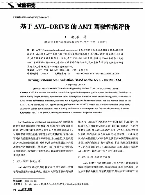
基于AVL-DRIVE系统的AMT驾驶性能评价王勐;崔伟【摘要】Based on AVL-DRIVE system, AMT system driveablity test has been carried out on F3000 tractor in Shanxi Automobile, and the test result has been evaluated and analyzed to find out defects of driveability as subsequent improvement direction of AMT automobile.%基于AVL-DRIVE 系统,在陕汽F3000牵引车上进行AMT系统驾驶性能的测试,并对测试结果进行评估分析,找出车辆在某些驾驶性能方面存在的不足,作为AMT车辆的后续改进方向。
【期刊名称】《中国重型装备》【年(卷),期】2015(000)003【总页数】4页(P24-27)【关键词】AMT;AVL-DRIVE;驾驶性能;评估【作者】王勐;崔伟【作者单位】陕西法士特汽车传动工程研究院,陕西710119;陕西法士特汽车传动工程研究院,陕西710119【正文语种】中文【中图分类】U463.212+.31Wang Meng, Cui WeiKey words:AMT; AVL-DRIVE; driveability; evaluationAMT(Automated mechanical transmission)系统的开发需要大量道路试验来评价起步、加速、换挡等重要的驾驶性能,AVL-DRIVE系统在大量专业人员的经验基础上对商用车的特征性能进行客观分析与质量控制,通过各种不同的传感器采集数据和车辆参数,如加速度、发动机转速、车速、加速踏板位置、振动等,将这些参数通过中央处理单元发送给计算机,使用AVL-DRIVE软件进行分析,从而能够在一定程度上避免驾驶员对车辆驾驶性能的主观误判。
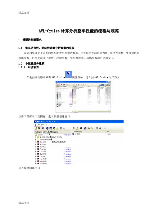
精品文档AVL-Cruise计算分析整车性能的流程与规范1 模型的构建要求1.1 整车动力性、经济性计算分析参数的获取收集和整理关于该车的整车配置组件参数数据。
主要包括发动机动力性、经济性参数;变速箱档位速比参数;后桥主减速比参数;轮胎参数;整车参数等。
具体参数项目见附录1。
1.2 各配置组件建模1.2.1 启动软件在桌面或程序中双击AVL-Cruise快捷图标,进入到AVL-Cruise用户界面,点击下图所示工具图标,进入模型创建窗口。
进入模型创建窗口1.2.2 建立整车参数模型进入模型创建窗口后,将鼠标选中Vehicle Model,鼠标左键点击整车图标,按住左键将图标拖曳到建模区,如下图所示:双击整车图标后打开整车参数输入界面,根据参数输入要求依次填写数据:Author :此处填写计算者,不能用中文,可以用汉语拼音和英文,该软件所有填写参数处均不能出现中文。
Comment :此处填写分析的车型号。
Notice1、Notice2、Notice3:此处填写分析者认为需要注意的事项,比如特殊发动机型号等,没有可 以不填。
1.2.2.1 整车参数数据填写规则进入模型创建窗口后,将鼠标选中Engine Model ,鼠标左键点击发动机图标,按住左键将图标拖曳到建模区,如下图所示:作者名称、注解说明,可以不填注解说明,可以不填油箱容积 内外温差:0试验台架支点高度:100内外压差:0 牵引点到前轴距离轴距空载、半载、满载下整车重心到前轴中心距离、重心高度、鞍点高度、前轮充气压力、后轮充气压力整备质量 整车总重迎风面积风阻系数前轮举升系数后轮举升系数双击发动机图标后打开发动机参数输入界面,根据参数输入要求依次填写数据:1.2.3.1 发动机参数输入规则按照图示箭头位置单击按钮,弹出外特性输入窗口:此处根据厂家提供的发动机数据输入转速与扭矩关系发动机转速与扭矩的关系从外特性数据表中可以直接得到;填写时注意对应关系即可。
基于AVL-DRIVE的AMT驾驶性能评价摘要:AVL-DRIVE是一种新型的车辆驾驶仿真系统,具有良好的可扩展性和可定制性,广泛应用于汽车领域。
本文通过对AVL-DRIVE中AMT系统的建模和仿真实验,评估了AMT在不同路况和驾驶状态下的性能表现,分析了其优点和不足之处。
研究结果显示,AMT可以有效提高驾驶舒适度和燃油经济性,在城市交通和高速公路等不同驾驶场景下均表现出良好的适应性。
关键词:AVL-DRIVE;AMT;驾驶性能评价;燃油经济性;驾驶舒适度正文:概述自动手动变速器(AMT)是一种新型的变速器系统,通过电子控制单位(ECU)和离合器控制单元(CCU)实现变速操作。
相较于传统的手动变速器和自动变速器,AMT具有快速响应、高效节能和低噪音等优点,被广泛应用于汽车和轻型商用车等领域。
为了评估AMT在不同驾驶场景下的性能表现,本文基于AVL-DRIVE车辆驾驶仿真系统,对AMT进行了建模和仿真实验。
建模分析在AVL-DRIVE中,我们使用Matlab/Simulink进行AMT系统的建模。
其中,ECU和CCU分别由控制模块和离合器模块组成,通过信号传输线连接起来。
在系统建模过程中,我们需要准确设置各个参数值,如变速箱齿比、离合器转矩和滤波时间等。
通过对不同参数组合的实验仿真,我们较为准确地确定了AMT的控制策略和操作规律。
仿真实验在仿真实验中,我们设计了不同场景下的驾驶路况,包括城市道路、高速公路和山路等。
我们选择了一辆装有AMT系统的SUV作为测试对象,通过控制方向盘和油门等要素,模拟真实的驾驶行为。
我们对不同路况和驾驶状态下的AMT操作进行了详细记录和数据分析,并对其性能表现进行了评估。
结果分析通过仿真实验,我们获得了AMT在不同驾驶场景下的性能数据,包括燃油经济性、驾驶舒适度和加速性能等方面。
我们发现,在城市交通拥堵和高速公路等高速行驶场景下,AMT系统能够保持平稳的加速性能,并且具有更好的燃油经济性表现,相较于传统的手动变速器和自动变速器,其能够减少燃料消耗和排放。

AVL-DRIVEAVL LIST GMBHHans-List-Platz 1 A-8020 Graz / Austria Phone: +43 316 787-2619 Fax: +43 316 787-2240Edition: V02, September 2009Subject to alteration Printed in Austria by AVL LIST GMBH GrazTruck benchmark guidance withAVL-DRIVE V3.1.1File: AVL-DRIVE Truck benchmark guidance_v02_CD.docThe present “Truck benchmark guidance with AVL-DRIVE” represents a recommendation for AVL-DRIVE measurements. This test cycle is not a “must” for driveability evaluation, but it might be helpful for the driver using these instructions. This test cycle was set up to assure that all AVL-DRIVE relevant events can be measured.We want to point out that some manoeuvres do not fulfil the road traffic regulations of most countries due to exceeding the speed limits. Therefore it is recommendable to use a test track, if available, or suspend certain suggestions.For a benchmark of different Trucks a test cycle should be chosen to achieve comparable results.Truck benchmark guidance with AVL-DRIVETruck benchmark guidance with AVL-DRIVE (2)1.Prerequisites (in addition to a standard/minimum AVL-DRIVE setup) (3)1.1.General (3)1.2.Sensors (3)1.3.Measurement channel information (4)1.4.Vehicle configuration file (5)1.5.View- and Graph-configuration files (7)1.6.Measurement file structure and estimated duration (8)2.Preparations in the Truck (10)2.1.Payload (10)2.2.Signal calibration (garage / workshop) (10)2.3.Signal calibration (test track) (11)3.Measurements (17)3.1. CoastDown (17)3.2. Motoring and Full Load Acceleration (18)3.3. Continuous Brakes (18)3.4. Warm up measurement (19)3.5. EngineStart_IdleAll_ThrottleResponse_EngineStop (20)3.6. Constant Speed (21)3.7. Driveaway_VehicleStop (22)3.8. Driveaway_VehicleStop_D (22)3.9. Driveaway_HillClimbing, Shifting on Gradient (23)3.10. Manoeuvering (24)3.11. Acceleration PT rising Pedal (24)3.12. Acceleration PT constant Pedal (25)3.13. Tipin Tipout G3_10 (26)3.14. GearShift (27)3.15. GearShift AMT (28)3.16. Cruise Control (29)Explanation of the symbols:…means …do it in the workshop / garage“... means “do it on the desktop”… means “do it in the car on a horizontal surface”… means “do it on the test track / road”… means “pay special attention”1. Prerequisites (in addition to a standard/minimum AVL-DRIVE setup)1.1. GeneralFor benchmark evaluation all Trucks must have the identical sensor equipment and AVL-DRIVE setup1.2. Sensors∙3-axial acceleration sensor for longitudinal chassis acceleration: → mounted stiffly in the center of gravity (or as close as possible)→ most equal position in all Trucks to be benchmarked∙3-axial acceleration sensor for longitudinal cabin acceleration:→ mounted stiffly in the center of gravity (or as close as possible)→ most equal position in all Trucks to be benchmarked∙1-axial acceleration sensor for vertical acceleration(used for rough road- compensation)→ mounted on the wheel carrier of a front axle∙Vibration sensors→ mounted on the gear lever (only for MT Trucks), the steering wheel, driver’s seat rail∙Acceleration sensors Driver`s seat longitudinal, vertical / microphone →mounted on the driver’s neck rest1.3. Measurement channel information→ Pleas e refer also to the chapter “Specifications for signals supplied bythe vehicle” in the AVL -DRIVE product guide !!→ ALL CHANNELS MUST BE CHECKED TO PLAUSIBILITY VERY CAREFULLY BEFORE MEASUREMENT !!1.4. Vehicle configuration file∙Set tip-in / tip-out filter settings manuallyRecommendation: 3, 5, 6, 7, 8, 8.8 Hz∙Set DPI values to 1.00 manually…to calculate DPI’s out of the first full load measurements∙Activate rough road compensation if wantedRecommendation:Filter window size: 8 samples, filter threshold: 5 dB∙Set rough road detection if wantedRecommendation for open road driving:Limit low 0,2 m/s², Limit high 10 m/s²Recommendation for test track driving (very smooth surface):Limit low 10 m/s², Limit high 20 m/s²∙Activate assessment of Noise & VibrationsTo be found ino Vehicle▪Edit work parameterRecommendation:Noise →only used in “Noise”, Vibration s →“standard”∙Fill up the tank and weigh the Truck (without driver), enter correct mass in the technical information (paypoad = Freight, Driver, Co driver,measurement equipment).ALL SETTINGS DEFINED IN “Trigger01” / “Trigger02” SHOULD BEIDENTICAL FOR ALL BENCHMARK TRUCKS !!1.5. View- and Graph-configuration filesIt is recommended to set up the view configuration and the graph configurations in advance and to use the same configurations for all measurements. In that case an anomaly of any signal will be detected more easy.Example:1.6. Measurement file structure and estimated durationFor easier handling of all the measurement files collected for e.g. a benchmark report it is recommended to keep the file names always the same. Example given (including an estimated duration):File structure AT TrucksTotal (hours)Approx. 19 h2. Preparations in the Truck2.1. PayloadEnter the correct payload for the planned measurement ride.2.2. Signal calibration (garage / workshop)-Make sure that the Truck stands on a absolutely horizontal surface-Start a measurement and perform an automatic calibration procedure-Compare the calibrated values with the recommendation given in the frame “sensor calibration information”for 1-axis and 3-axis accelerometer and be sure to be within the ranges (e.g. for a 3-axis accelerometer the longitudinal acceleration signal should be 0.0 +/-0.3 and if the calibrated values read -0.194, it’s okay)-Check the acceleration signal plausibility by moving the car slightly forward and brake to standstill again: during acceleration the acceleration signals ofthe chassis and the seat must be positive, during braking negativeThis is recommended before each single measurement!2.3. Signal calibration (test track)2.3.1 Use the Self Learning Wizard-Learn the gear ratios, clutch touch point (MT Trucks), frequencies2.3.2 Check the plausibility of all signals again-Status of the brake-Status of air condition compressor-Accelerator pedal position-MT-Trucks: Clutch pedal travel-Brake pedal position-Gear signal-Selector lever position (automatic mode and manual mode)-Air compressor2.3.3 First friction parameter estimationThe first estimation defines the bandwidth of the friction wizard (lo/hi) in order to narrow down the amount of possible mathematical solutions for the friction curve.-Open the Self Learning Wizard-Open Tab General – Vehicle and Engine-Enter Truck mass and payload-Open Tab Self Learning – Resistance Coefficients -Choose option “A0, B0” Calculation-Choose option “C0” cw*A Input-Enter value for ”cw*A”(manufacturer’s value)-Press Finish and save Vehicle Configuration-Measure full load accelerations in the gears 8 to 10, (see also chapter 3.2) o Turn off the air conditiono Clutch must be closedo MT-Trucks: accelerate to ~2000 rpm, motoring down to ~900 rpm, afterwards full load acceleration until rpm limiter intervention o Maybe the rpm-thresholds for “engine speed at max. power” and “engine speed at max. torque” must be changed in order to reachthem (and to force the trigger machine of AVL-DRIVE to start)-Analyze the measurement and change the DPI settings so that the signal of the actual power fits to the nominal power (given in the technical information) in the tab sheet “Full Load” of the AVL-DRIVE analyzer.2.3.4 Coast down measurement (see also chapter 3.1)-Select a leveled, straight road with low traffic which is long enough, choose a calm day if possible (no winds)-Turn off the air condition-Speed up to about 80km/h (or vmax), shift to neutral an let the car coast down to about 40 km/h (or to standstill if possible) -Avoid lane changes and slipstream driving-Repeat that procedure at least two times in one direction and two times in the opposite direction (to compensate potential wind influence) -Due to Load conditions and test track it can be necessary to split the measurements (eg. 80 -> 40, 60 -> 20, 40 ->0, ..)-For Trucks it is recommended to do the measurement in fully loaded condition2.3.5 Friction values calculation with coast down measurement-Open the Self Learning Wizard-Open Tab Self Learning – Resistance Coefficients-Choo se option “C0” Detection-Press “Friction Wizard”-Load coast down measurement-Choose “Auto Detection” in the pop-up window-Check if coast downs were detected correctly (if not select them manually)-Move the coast downs from the same direction to the same Coast Down List-Press “Calc”-If the road was leveled all curves should be more or less aligned-If there was a road gradient or if it was windy the curves measured in the same direction should show the same tendency (above/below the calculated curve)-The calculated Coast Down Curve should therefore be in between the curves measured in the both directions-In case the result doesn’t match an advanced user’s opinion the friction coefficient values might be adapted (middle column) manually. Entered values must not exceed the lo/hi limits (left/right column)2.3.6 DPI re-check-Repeat the full load accelerations in the gears 8 to 10 as described in chapter 2.3.2 (or use the PCS-mode of AVL-DRIVE to simulate thealready taken acceleration measurements)-Check the DPI settings as described in chapter 2.3.3.3. Measurements3.1. CoastDown3.2. Motoring and Full Load Acceleration3.3. Continuous Brakes3.4. Warm up measurement3.5. EngineStart_IdleAll_ThrottleResponse_EngineStop3.6. Constant Speed3.7. Driveaway_VehicleStop3.8. Driveaway_VehicleStop_D3.9. Driveaway_HillClimbing, Shifting on Gradient3.10. Manoeuvering3.11. Acceleration PT rising Pedal3.12. Acceleration PT constant Pedal3.13. Tipin Tipout G3_103.14. GearShift3.15. GearShift AMT3.16. Cruise Control。

AVL CRUISE软件功能简介AVL CRUISE—车辆动力学仿真分析平台AVL CRUISE 软件可以轻松实现对复杂车辆动力传动系统的仿真分析,通过其便捷通用的模型元件,直观易懂的数据管理系统以及基于工程应用开发设计的建模流程和软件接口,AVLCRUISE软件已经成功的在整车生产商和零部件供应商之间搭建起了沟通的桥梁。
软件的主要特点简述如下:1.便捷的建模方法和模块化的建模手段使得不同项目组可以对模型进行方便快捷的整合。
可以快速搭建各种复杂的动力传动系统模型,可同时进行正向或逆向仿真分析;2.可以实现对车辆循环油耗(针对不同的循环工况),等速油耗(任意档位和车速下),稳态排放,最大爬坡度(考虑驱动防滑),最大牵引力(牵引功率),最大加速度,最高车速,原地起步连续换档加速,超车加速性能(直接档加速性能),车辆智能巡航控制,制动/反拖/滑行等一系列车辆性能的计算分析;3.CRUISE软件与AVL BOOST软件的耦合仿真可以实现对发动机瞬态特性的仿真分析;与FLOWMASTER软件或KULI软件的耦合仿真可以实现车辆热管理系统(VTMS)的设计及仿真分析;4.在基于传统车辆模型的基础上可以快速搭建纯电动汽车或混合动力车辆模型,并可通过与Matlab(API,DLL,Interface)或C(BlackBox)语言的接口实现整车控制策略的设计开发;能够便捷的对新型动力传动模式(AT,AMT,DCT,CVT 等)及其控制策略进行研究分析;5.内置Function函数,兼容C语言的程序格式,使用户在不需要第三方程序的前提下便捷的进行相关控制策略的设计和开发;6.根据预先设定的动力性、经济性或排放性指标,可以对模型中的参数进行快速优化组合,并可以对动力传动系统进行匹配优化(DOE参数化研究和多动力总成匹配研究);7.采用与Oracle对接的数据库管理体系,便于进行系统的管理和资源分配,提高了数据管理的安全性,同时方便实现CRUISE软件不同使用群体之间的数据交换和数据读取;强大的数据搜寻和对比功能,使用户在面对大量的数据的情况下可根据自己设定的边界条件便捷的进行数据的获取和对比;8.可以与硬件系统(如:AVL In-Motion,dSPACE,ETAS等)进行联合仿真,满足用户对于车辆系统动态实时(Real Time)仿真分析的需求;可对动力总成及其相关联的ECU控制策略进行分析和调试,实现车辆动力学的快速原型开发(RCP)和硬件在环仿真功能(HIL),极大的提高了开发效率并缩短了开发流程;9.提出了动力总成分层建模的方法,可以将动力总成的不同元件搭建在用户自己设定的不同层中,使得建模过程更加直观和便捷,可独立对动力总成中某一部件进行仿真分析(无须搭建整个车辆模型),极大的降低了对于车辆建模所需参数的要求;可根据用户自定义的目标参数,对驾驶员模型进行系统优化分析;10.通过与AVL DRIVE以及IPG CarMaker的联合仿真可以进行包括:牵引力控制,制动稳定性分析,行驶平顺性以及换档品质评价等方面的仿真分析;。

AVL解决方案一、概述AVL解决方案是一种用于车辆定位和跟踪的先进技术,通过使用全球定位系统(GPS)和通信技术,可以实时监控和管理车辆的位置、速度和状态信息。
本文将详细介绍AVL解决方案的功能、优势以及应用领域。
二、功能1. 实时定位:AVL解决方案可以实时获取车辆的准确位置信息,并将其显示在地图上。
用户可以通过电子地图界面追踪车辆的挪移轨迹。
2. 路线规划:利用AVL解决方案,用户可以规划车辆的最佳行驶路线,以提高效率并减少行驶时间。
系统会根据实时交通信息和车辆状态,为用户提供最优的行驶路线。
3. 报警功能:AVL解决方案可以设置各种报警功能,如超速报警、入侵报警等。
一旦车辆发生异常行为,系统会即将发送警报通知用户,以确保车辆安全。
4. 数据分析:AVL解决方案可以采集和分析大量的车辆数据,如行驶里程、油耗、驾驶行为等。
用户可以通过数据分析,了解车辆的使用情况,并根据数据结果进行优化管理。
5. 远程控制:通过AVL解决方案,用户可以实现对车辆的远程控制,如远程锁车、解锁车门等。
这为车辆管理者提供了更大的便利性和安全性。
三、优势1. 实时监控:AVL解决方案可以实时监控车辆的位置和状态,提供准确的数据支持,匡助用户更好地管理车辆。
2. 提高效率:通过AVL解决方案,用户可以实现对车辆行驶路线的优化规划,减少行驶时间和成本,提高工作效率。
3. 增强安全性:AVL解决方案可以提供各种报警功能,及时警示用户车辆的异常行为,保障车辆的安全。
4. 数据分析:AVL解决方案可以采集和分析大量的车辆数据,匡助用户了解车辆的使用情况,进行数据驱动的管理决策。
5. 远程控制:AVL解决方案支持远程控制功能,用户可以通过手机或者电脑远程操作车辆,提高便利性和安全性。
四、应用领域1. 物流行业:AVL解决方案可以匡助物流公司实时监控货物的运输过程,提高物流效率和安全性。
2. 出租车行业:AVL解决方案可以匡助出租车公司实时监控车辆的位置和行驶状态,提供更好的服务质量。
10.16638/ki.1671-7988.2021.012.036AVL DRIVE在整车驾驶性能开发的运用陈铭1,2,黄炯1,2,魏喜乐1,2(1.江铃汽车股份有限公司整车性能及测试部,江西南昌330001;2.江西省汽车噪声与振动重点实验室,江西南昌330001)摘要:文章利用A VL DRIVE系统结合测试的加速度、电流、CAN网络信号对车辆驾驶性进行客观化测试与评估,使驾驶性问题可视化,通过分析客观数据得出车辆差异点及问题点,制定不同工况下的差异化目标。
使用表明A VL DRIVE在整车驾驶性能开发中有良好的助力效果。
关键词:AVL DRIVE;驾驶性;客观评估;整车性能中图分类号:U461 文献标识码:A 文章编号:1671-7988(2021)12-117-03Application of A VL DRIVE in Vehicle Driveability DevelopmentCHEN Ming1,2, HUANG Jiong1,2, WEI Xile1,2( 1.Vehicle performance and test department Jiangling Automobile Co., Ltd., Jiangxi Nanchang 330001;2.Jiangxi Key Laboratory of automobile noise and vibration, Jiangxi Nanchang 330001 )Abstract:The A VL DRIVE system is used to objectively evaluate the vehicle drivability with the tested acceleration, current and CAN network signals, so as to visualize the driveability problems. Through the analysis of objective data, the vehicle differences and problem points are obtained, and the differentiation objectives under different conditions are formulated.The use shows that A VL DRIVE has a good boost effect in the development of vehicle driving performance. Keywords: A VL DRIVE; Driveability; Objective evaluate; Vehicle attributesCLC NO.: U461 Document Code: A Article ID: 1671-7988(2021)12-117-03前言车辆的驾驶性能的评估及验收结果在以往的开发中主要靠工程师的主观感觉,这种方法对评估人员的经验有较高要求且受个人因素影响,如引入客观的评价手段,则可以屏蔽掉主观评估的不稳定性[1]。
0 引言随着社会经济的发展与进步,家用汽车的数量逐渐增多,用户的驾驶水平也有所提升。
用户对轻型汽车驾驶性的需求也在不断地提高,对动力性、舒适性以及NVH等性能的要求更加严格,这就对车企整车开发的技术提出了更高的要求。
汽车的驾驶性是在汽车纵向行驶过程中人车交互的综合感知,包括汽车的静态性能和动态响应能力。
汽车的驾驶性可以体现车型的定位和品牌的能力,是影响产品市场竞争力的重要因素。
在满足安全性和经济性的前提下,舒适性和人性化必将成为未来轻型汽车性能开发的主要方向[1]。
1 驾驶性评价方法可以从不同角度、使用不同方法对汽车的驾驶性能进行评价。
目前常用的方法主要有主观评价和客观评价。
由于驾驶性的构成较为复杂,包括汽车在不同方向上的动态响应,因此主观评价可以从汽车驾驶的多个维度进行评价;客观评价能对汽车的驾驶性进行量化,通过分析可以将汽车驾驶性与车辆性能的参数结合在一起,从而指导开发性能参数。
主客观评价汽车驾驶性针对的是汽车不同状态下的性能。
客观评价主要对车辆的稳态性能进行评估;而主观评价主要是对车辆的瞬态品质进行评估[2]。
1.1 主观评价主观评价是指驾驶员在驾驶时可以通过五官和身体的内部感觉对车辆的动态响应做出主观评价。
国外企业使用AUDIT评价法、SAE主观评车标准以及日本的五分制打分等。
国内驾驶性评价起步较晚,但近几年,国内企业和研究机构都开展了对驾驶性主观评价的相关研究,例如中国汽车研究中心2017年发布了EV-TEST主观评价管理规则,其评分方法见表1。
国外相关学者使用不同方法对汽车的驾驶性进行综合评价,例如驾驶性指标体系构建、多元线性回归虚拟评价、神经网络虚拟评价以及仿真分析与测试评价方法等。
国内也在开展相关研究,并逐步形成了基于模糊理论、动态规划等算法的驾驶性评价方法。
1.2 客观评价客观评价是指在特定工况下通过一系列传感器对车辆进行测试,采集车辆的控制参数和状态参数,分析所得的结果并建立汽车相关性能与参数之间的联系。
基于AVL Cruise的某重型商用车动力性、经济性分析及优化摘要:本文结合AVL Cruise仿真平台,对某重型商用车的动力性、经济性进行分析与优化。
在分析了该车型的性能参数与载荷要求后,设计了不同的工况下的仿真模型,运用优化算法对发动机参数进行优化,得出了最优化的发动机参数,并评估其性能表现。
结果表明,优化后的发动机能够满足车辆运行要求,实现了动力性与经济性的平衡,具有较高的经济性和驾驶舒适性。
关键词:AVL Cruise;商用车;动力性;经济性;优化算法正文:一、引言随着现代物流业的飞速发展,越来越多的商用车投入到货运、物流等领域中。
对于这类车型,动力性和经济性是其最重要的性能指标之一。
为了满足市场的需求,车辆制造商不断地提升商用车的动力性能和经济性能,以提高车辆的可靠性和利润率。
AVL Cruise是一种基于Matlab/Simulink平台的汽车仿真工具,可用于评估和优化车辆性能。
本文将结合AVL Cruise仿真平台,对某重型商用车的动力性、经济性进行分析与优化,旨在提高车辆的性能表现和运营效益。
二、分析模型1. 车辆性能参数对于商用车来说,其运行状态和载荷要求是确定性能参数的关键因素。
本文选取某重型商用车作为研究对象,其主要性能参数如下:①车重:25吨。
②最高时速:70km/h。
③载荷:25吨。
④发动机最大功率:300kW。
⑤变速器齿比范围:10~0.8。
2. 仿真模型基于以上性能参数,本文设计了不同工况下的仿真模型,包括起步、加速、行驶和制动等工况。
其中,速度和时间分别受到限制,以确保车辆在安全的范围内行驶。
在仿真过程中,考虑到车辆质量、空气阻力、滚动阻力等对车辆性能的影响,以实现对车辆动力性、经济性的准确分析。
三、优化算法优化算法是本文研究的重点,其目的在于优化发动机参数,以提高车辆的动力性和经济性。
本文采用遗传算法作为优化算法,并设计了相应的遗传算法模型,在仿真平台上运行,获得最优化的发动机参数。
AVL试验技术在内燃机性能测试中的应用一、背景介绍内燃机是一种普遍应用于交通运输、工业领域以及家用电器中的引擎。
内燃机的性能对于使用它的设备具有至关重要的作用。
为了保证内燃机的稳定性与安全性,往往需要进行内燃机性能测试。
在内燃机性能测试中,AVL试验技术已经成为了一种广泛应用的手段。
二、AVL试验技术的概念AVL是公司名为AVL List Gmbh的缩写。
AVL试验技术是一种汽车研发和测试技术。
通过AVL试验技术可以实现对内燃机各个方面性能指标测试,包括发动机功率、扭矩、燃油经济性等。
三、AVL试验系统的构成AVL试验系统由测试对象、测试设备、数据采集系统以及分析软件等构成。
其中,测试对象就是指内燃机本身。
测试设备包括测功机等仪器,数据采集系统则是将内燃机的各项数据进行记录与分析。
分析软件则是对数据进行分析处理,生成测试报告等相关文档。
四、AVL试验技术在内燃机性能测试中的应用AVL试验技术广泛应用于内燃机性能测试之中。
例如:1、发动机功率试验;2、扭矩试验;3、燃油经济性试验等。
其中,发动机功率试验是最为常见的试验之一。
通过此项试验可以获得内燃机的最大功率值及相应的转速。
扭矩试验则是用于测定某一特定转速下内燃机产生的最大扭矩值和扭矩-转速曲率。
燃油经济性试验则是对内燃机的燃油经济性进行测试,目的是在充分考虑减少污染下提高内燃机的综合效益,让内燃机具有更好的性能表现。
五、AVL试验技术在内燃机性能测试中的优势1、测试精度高: AVl试验技术可以实现对内燃机各项指标的准确测量,避免人工操作误差等因素,提高了测试的精度。
2、测试速度快:AVL试验技术采用的数字化测试技术降低了测试时间,提高了测试效率。
3、测试结果准确无误:AVL试验技术具有无误判定和自动校准功能,结果精准可靠。
六、AVL试验技术的不足1、成本高:AVL试验技术的成本很高,相应的设备设施和技术人员的培训需花费大量时间和金钱。
2、复杂度高:AVL试验技术需要专业人员进行操作,并进行专门的数据处理,要求实施过程密切配合测试对象情况、技术需求等多个因素。
AVL解决方案一、概述AVL解决方案是一种用于实时监控和管理车辆运营的系统。
该解决方案基于先进的AVL(Automatic Vehicle Location)技术,结合GPS(Global Positioning System)定位、无线通信和云计算等技术,能够实时获取车辆位置、状态和行驶数据,并通过数据分析和处理,提供全面的车辆管理和调度功能。
本文将详细介绍AVL解决方案的功能、工作原理、优势和应用场景。
二、功能1. 实时定位和监控:AVL解决方案可以实时获取车辆的位置信息,并在地图上显示车辆的实时位置。
用户可以通过Web界面或者挪移应用程序随时查看车辆的位置和轨迹,实现对车辆的实时监控。
2. 车辆状态监测:AVL解决方案可以监测车辆的状态,包括车辆的速度、里程、油耗、发动机状态等。
用户可以通过系统界面查看车辆的状态信息,及时了解车辆的运行状况。
3. 报警与预警:AVL解决方案可以根据用户设定的规则和条件,实现对车辆的报警和预警功能。
例如,当车辆超速、进入禁区或者发生故障时,系统会自动发送报警信息给相关人员,以便及时采取措施。
4. 路线规划和导航:AVL解决方案可以根据用户设定的目的地和优化算法,为车辆规划最优的行驶路线,并提供导航功能。
这可以匡助司机选择最短、最快或者最经济的路线,提高运输效率和节约成本。
5. 数据分析和报表:AVL解决方案可以对车辆的行驶数据进行分析和统计,并生成相关的报表。
用户可以通过系统界面查看车辆的行驶轨迹、停留时间、油耗统计等数据,以便进行运营分析和决策。
6. 车辆调度和任务管理:AVL解决方案可以实现对车辆的调度和任务管理。
用户可以根据实际需求,将任务分配给不同的车辆,并通过系统界面查看任务执行情况,以便及时调整和优化车辆调度。
三、工作原理AVL解决方案主要由车载终端设备、通信网络和服务器组成。
车载终端设备安装在车辆上,通过GPS定位模块获取车辆的位置信息,并通过无线通信网络将数据传输到服务器。