热量计说明书
- 格式:doc
- 大小:878.00 KB
- 文档页数:19

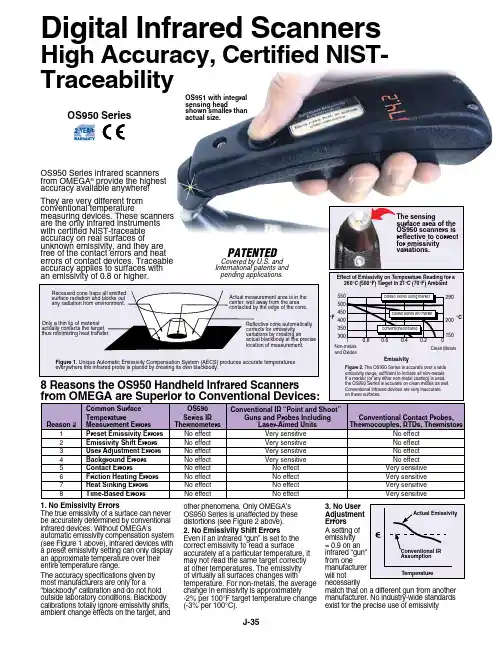
Thermal Energy Meters standard 22PE-1U.. with glycol compensation Edition 2022-06/CPoE2Thermal Energy Meters 22PE-1U..Table of ContentsNotesGeneral information Legal Notice Installation notes 4 6 7Supply voltage11 Display and operating elements12 Wiring diagramsNotesConnection assignmentAnalogue output connection13Connections to BACnet, Modbus, MP-Bus14 Sensor connections (optional)Connection to M-Bus15 Commissioning16 Error codes18 Exchanging the sensor module20 Sensor module as a spare part23AccessoriesOptional accessories244Subject to technical modifications Thermal Energy Meters 22PE-1U..NotesUse and functionThe thermal energy meter records the thermal energy in closed heating, cooling systems or heating/cooling systems. It is equipped with automatic glycol compensation and automatically and continuously measures the glycol content in the fluid, compensates for it and thus ensures the reliable measure -ment of the thermal energy. The glycol content (%) can be read out with the Belimo Assistant App and the web server. Designed as a multifunctional device, the thermal energy meter can be operated as a heat meter, cooling meter or heat/cooling meter. In addition, it can be installed either in the return or in the supply of the system. The choice of installation in the return or in the supply is made during commissioning with the web server or with a smart-phone and the Belimo Assistant App.Scope of delivery–Thermal energy meter –Insulation shell –Silicone grommet –Installation instructions Water quality requirementsThe measuring stability of the meter is only given if the water quality meets the conditions of AGFW recommendation FW-510 and VDI 2035.Energy meter installationBefore installing and commissioning the thermal energy meter, carefully study the operating manual to prevent errors during installation and commissioning.The operating manual is valid for the following thermal energy metersProduct type from Belimo DN DN (″)G (″)Nominal flow qp (m 3/h)22PE-1UC 151/23/4 1.522PE-1UD 203/41 2.522PE-1UE 251 1 1/4 3.522PE-1UF 32 1 1/4 1 1/2622PE-1UG 40 1 1/221022PE-1UH 502 2 1/215General information5Subject to technical modificationsThermal Energy Meters 22PE-1U..Belimo Assistant Appintegrated web server When commissioning the thermal energy meter, the system-specific parame -ters must be defined using the Belimo Assistant App or the integrated webserver. Communication from the smartphone to the thermal energy meter takes place via NFC (Near Field Communication). Communication from the web server (PC) to the thermal energy meter takes place via an Ethernet cable and the RJ45 connection. For further information on the integrated web server,please refer to the web server manual.Logic moduleStructure of the thermalenergy meter The thermal energy meter consists of a sensor module with connected temperature sensors, which houses the calculator unit and measuring system,as well as the logic module, which connects the thermal energy meter to the power supply and provides the bus and near field communication interface. The sensor module is available as a spare part.6Subject to technical modifications Thermal Energy Meters 22PE-1U..Commissioning staffThe thermal energy meter has left the factory in perfect condition. All installa-tion work may only be carried out by a trained and authorised specialist.Calibration CertificateAssistant App or via the Belimo Cloud frontend. ApplicationWith regard to legal transactions, regional and local regulations must be observed. Belimo also offers thermal energy meters that have type approval as heat meters in accordance with the European Measuring Instruments Directive (MID) (part number 22PEM-1U..).Use of Belimo Cloud ServicesUse of Belimo Cloud Services is governed by the "Terms of Use for Belimo Cloud Services" in their currently valid version.Legal NoticeNear field communication connectionThe near field communication logo on the thermal energy meter indicates that the device can be operated with the Belimo Assistant App.Requirement: –Near field communication or Bluetooth-enabled smartphone –Belimo Assistant App (Google Play and Apple App Store)Near field communication: position the near field communication-enabled smartphone on the thermal energy meter so that both near field communica -tion antennas of the smartphone and thermal energy meter are on top of each other.Bluetooth: connect the Bluetooth-enabled smartphone to the thermal energy meter via the Bluetooth to near field communication converter ZIP-BT-NFC.Technical data and operating manual can be found on the ZIP-BT-NFC data sheet.Near field communication Bluetooth7Subject to technical modifications Thermal Energy Meters 22PE-1U..DN 152025324050Installation positionInlet sectiona) Recommended installation position b) Prohibited installation position due to the risk of air accumulation c) Acceptable installation position in closed systems d) Installation directly downstream from valves is prohibited. Exception: if it is an open/close valve without constriction and is 100% open.e) Installation on the suction side of a pump is not recommended.f) The thermal energy meter must not be installed upside down.g) Upright to horizontal installation is permitted, but suspended installation is prohibited.h) In order to achieve the specified measuring accuracy, it is recommended to provide a straight flow calming section or inlet section in the direction of flow upstream from the thermal energy meter. This must be at least 5 x DN and have the same nominal size (DN) as the thermal energy meter.Installation notes8Subject to technical modificationsThermal Energy Meters 22PE-1U..Direction of flow The direction of flow indicated by an arrow on the logic module and flowmeasuring pipe must be complied with, otherwise the flow will be measuredincorrectly.Preventing cavitation To prevent cavitation, the system pressure at the output of the thermal energymeter must be at least 1 bar at qs (maximum flow) and temperatures up to90°C. At a temperature of 120°C the system pressure at the output of thethermal energy meter must be at least 2.5 bar.Installation of temperature sensor T1The temperature sensor T1 is installed via a thermowell.The connecting cable of temperature sensor T1 should not be laid along hotpipes or wound around them, as the wire resistance and its temperaturedependency affect the measurement result of temperature sensors in two-wiretechnology.9Subject to technical modificationsThermal Energy Meters 22PE-1U..Picture 1Installation in the return (default)Picture 1 shows the principle. The thermal energy meter is located in the return of the consumer. Temperature sensor T2 installed directly in the sensor module records the return temperature. The external temperature sensor T1 can be installed via a thermowell (A-22PE-A07 for DN 15…50 included in the scope of delivery) or a T-piece with thermowell located in the supply (A-22PE-A0.. available as an accessory).When installing the thermal energy meter, the direction of flow must beconsidered. The direction of flow is indicated by the arrows on the flow body (on both sides) and on the logic module. The thermal energy meter is installed between two pipe connectors (available as accessories EXT-EF-..D).Temperature sensors T1 and T2 are permanently connected to the thermal energy meter. The cable length must not be changed. If the sensor module is replaced, both temperature sensors T1 and T2 are also replaced.Assignment and parametrisationThe web server or the Belimo Assistantapp must be used to inform the thermalenergy meter that it is in the return (see also the "Commissioning" chapter).T 1T 2T 1T 2T T Σ000F l o wT 1EXT-EF-..DEXT-EF-..DA-22PE-A0..10Subject to technical modifications Thermal Energy Meters 22PE-1U..Installation in the supply (alternative)Picture 2 shows the principle (alternative). The thermal energy meter is located in the supply. Temperature sensor T2 installed directly in the sensor module records the supply temperature. The external temperature sensor T1 can be installed via a thermowell (A-22PE-A07 for DN 15…50 included in the scope of delivery) or a T-piece with thermowell located in the return (A-22PE-A0.. available as an accessory).When installing the thermal energy meter, the direction of flow must beconsidered. The direction of flow is indicated by the arrows on the flow body (on both sides) and on the logic module. The thermal energy meter is installed between two pipe connectors (available as accessories EXT-EF-..D).Temperature sensors T1 and T2 are permanently connected to the thermal energy meter. The cable length must not be changed. If the sensor module is replaced, both temperature sensors T1 and T2 are also replaced.Picture 2Assignment and parametrisationThe web server or the Belimo Assistantapp must be used to inform the thermalenergy meter that it is in the supply (seealso the "Commissioning" chapter).T 1T 1T 2T 1T 2F l o w T T Σ000T 1EXT-EF-..DEXT-EF-..DA-22PE-A0..11Thermal Energy Meters 22PE-1U.. Supply voltageSupply with AC/DC 24 V The supply voltage of the thermal energy meter is 24 Volt AC or DC.Supply via PoE Alternatively, the supply can be supplied via the Ethernet socket using PoE(Power over Ethernet with standard IEEE 802.3af). Activation of the PoE-supply DC 24 V for supplying the external active sensor (see also the chapter"Wiring diagrams") is carried out via the Belimo Assistant App (regardless ofwhether communication takes place via Ethernet). If the thermal energy meteris supplied with voltage via PoE, DC 24 V (max. 8 W) is available at wires 1 and2 for supplying external devices (e.g. actuator or active sensor).Caution: PoE may only be enabled if an external device is connected to wires 1and 2 or if wires 1 and 2 are insulated!Data storage in the event of a voltage interruption Every 120 minutes, the thermal energy meter stores the accumulated energy values (kWh) and volume (m3) into a persistent memory. After the voltage interruption, the system continues with the last persisted meter readings.12Thermal Energy Meters 22PE-1U..Display and operating elementsLEDStatusLights up c ontinuously Device starts Flashing Device in operationOffNo voltageStatus LED display13Thermal Energy Meters 22PE-1U..TTAnalogue output connectionWiring diagrams–Supply with isolating transformer–The wiring of the line for BACnet MS/TP and Modbus RTU must be carried out according to the relevant RS485 guidelines.–Modbus/BACnet: supply and communication are not galvanically separated. Connect earth signal for devices with one another.–Sensor interface: a sensor can optionally be connected to the thermalenergy meter. This can be a passive resistance sensor (e.g. Pt1000, Ni1000 or NTC), an active sensor (e.g. with a DC 0…10 V output) or a switching contact. As a result, the analogue signal of the sensor can be easily digitised with the thermal energy meter and transferred to the corre-sponding bus system.–Analogue output: an analogue output is available at the thermal energy meter. This can be selected as DC 0…10 V, DC 0.5…10 V orDC 2…10 V. For example, the flow or the temperature of temperature sensor T1/T2 can be output as an analogue value.–IP protection: IP protection is only guaranteed if either the Ethernet connec-tor socket is protected with the cover cap or a connected Ethernet cable is protected with the enclosed silicone grommet.–The clamp that fastens the silicone grommet must be tightened to a torque of 0.3 Nm.–Equipotential bonding: equipotential bonding must be installed on the flow body, if this is not already done via the pipelineNotesConnection RJ45 –PoE–BACnet IP –Modbus TCP –TCP/IP–Belimo Cloud –Web serverWire colours:1 = black, GND2 = red, AC/DC 24 V3 = white, sensor5 = orange, MP , DC 0…10 V6 = pink, C1 = D− = A7 = grey, C2 = D+ = BConnection assignmentNote: the connection to the Belimo Cloud is permanently available. Activation takes place via web server or Belimo Assistant App.14Thermal Energy Meters 22PE-1U..TT= AT= A TPoE with BACnet IP or Modbus TCP with analogue outputBACnet MS/TP or Modbus RTUBACnet MS/TP or Modbus RTU with analogue outputDWiring BACnet MS/TP or Modbus RTU (daisy chain)MP-Bus, supply via 3-wireMP-Bus via 2-wire local power supplyConnections BACnet, Modbus, MP-BusBACnet IP or Modbus TCPBACnet IP or Modbus TCP with analogue outputPoE with BACnet IP or Modbus TCP15Thermal Energy Meters 22PE-1U..Passive sensor connectionSwitch connectionActive sensor connectionM-Bus via M-Bus converter Sensor connections (optional)Connection to M-Bus via M-Bus converter G-22PEM-A01TTCP M-Bus parallel Modbus RTU or BACnet MSTP M-Bus parallel Modbus TCP or BACnet IPM-Bus parallel Modbus TCP orBACnet IP with PoETCPTTTT16Thermal Energy Meters 22PE-1U..CommissioningDefinition of the plant-specificp arametersWhen commissioning the thermal energy meter, the system-specific parame-ters must be defined using the Belimo Assistant App or the integrated webserver. Communication from the smartphone to the thermal energy metertakes place via NFC (Near Field Communication). Communication from theweb server (PC) to the thermal energy meter takes place via an Ethernet cableand the RJ45 connection. For further information on the integrated web server,please refer to the web server manual.Notes on smartphone with Bluetooth Bluetooth-enabled smartphones can be connected to the thermal energymeter via the "Bluetooth to near field communication converter" ZIP-BT-NFC(see chapter "near field communication connection" under "General notes").Possible settings–Choice of installation in return or in supply–Choice of bus system (MP-Bus/Modbus TCP/BACnet IP/Modbus RTU/BACnet MSTP) with choice of the physical bus address–IP setting, Belimo Cloud–Choice of medium (water or glycol)–Additional sensor interface–Terminal 5 configurable as analogue output DC 0…10 V or for MP-Bus–Choice of units, e.g. m3/h, l/min, gpm etc.Commissioning report Once commissioning has been completed, a commissioning report is availablevia the web server or Belimo Assistant App, in which all settings and basic dataare displayed clearly and in a structured manner. The commissioning reportcan be saved as a PDF file.17Thermal Energy Meters 22PE-1U..5 V10 VAdjustable functions, analogue outputAnalogue output U5Analogue output 0…10 V, terminal U5–Selectable as DC 0…10 V, DC 0.5…10 V or DC 2…10 V–Configurable for output of flow rate, power, temperature of temperature sensor T1/T2 or differential temperature of temperature sensor T1/T2 –Scaling: the maximum value, i.e. the flow corresponding to 10 V, can be scaled, thus achieving an optimised resolution. The maximum value is set to qp (qp = nominal flow rate) as a factory setting. The maximum value can be increased to a maximum of 1.2 x qp.–Flows greater than the maximum value are cut off, i.e. a voltage of 10 V is output.Heat/cooling meter changeoverThe thermal energy meter automatically switches between heat and cooling metering.Switching criteria:1. Installed in the returna) If the temperature value of T1 is higher than that of T2, then the TEM counts heat energy.b) If the temperature value of T1 is lower than that of T2, then the TEM counts cooling energy.2. Installed in the supplya) If the temperature value of T1 is higher than that of T2, then the TEM counts cooling energy.b) If the temperature value of T1 is lower than that of T2, then the TEM counts heat energy.LegendFactory Setting Alternative settingFlow18Thermal Energy Meters 22PE-1U..Error codesPermanent errorsError code MeaningErr 01Err 02Err 03Err 04Err 05Permanent communication error with non-volatile memory (SPI)Err 06Program code integrity check failedErr 07Parameter integrity check failedErr 08Err 09The data format in the non-volatile memory does not match the dataformat in the sensor uC softwareErr 10Integrity check of data in non-volatile memory failedErr 11An error counter has reached the maximum valueErr 12Err 13Err 14Err 15Err 1619Thermal Energy Meters 22PE-1U..Temporary errorsError code MeaningErr 17Err 18The ultrasonic path is interrupted (air bubbles in the system, connec-tion to ultrasonic transducers interrupted)Err 19Ultrasonic time of flight out of rangeErr 20Automatic gain controller out of range (problem with the ultrasonictransducer or wrong fluid)Err 21Err 22Volume accumulation failedErr 23Heat/cold accumulation failedErr 24The raw resistance measurement of temperature sensorT1 (external temperature sensor) or temperature sensor T2(temperature sensor integrated in the sensor module) is invalidErr 25Calculation errorErr 26Temperature sensor T2 (temperature sensor integrated in thes ensor module) is short circuitedErr 27Temperature sensor T2 (temperature sensor integrated in thes ensor module) is interruptedErr 28Temperature sensor T1 (external temperature sensor) is shortcircuitedErr 29Temperature sensor T1 (external temperature sensor) is interruptedErr 30Flow in reverse direction (backflow) detectedErr 31Flow above the upper limit valueErr 32Invalid flow20Thermal Energy Meters 22PE-1U..Exchanging the sensor moduleThe thermal energy meter is supplied with voltage via the logic module. The bus and near field communication interface is also available on the logic module. If the sensor module is disconnected from the logic module during replacement, the connecting cables can remain connected to the logic module and the system.Logic module of the thermal energy meterThe sensor module contains the integrated temperature sensor T2 and the external temperature sensor T1 is connected via a cable. If the sensor module is replaced, both temperature sensors T1 and T2 must also be replaced. The sensor module also houses the calculator unit and the ultrasonic flow measurement system.Sensor module of the thermalenergy meter21Subject to technical modificationsThermal Energy Meters 22PE-1U..a) Drain water circuit or close corresponding open/close valves b) Loosen the screws of the logic modulec) Separate the logic module and sensor moduled) Loosen the plastic nut of the temperature sensor T1 and pull the sensor out of the thermowelle) Loosen the screw connections on the sensor module and remove the sensor moduleSeparate the logic module and sensor module22Subject to technical modificationsThermal Energy Meters 22PE-1U..a) Place sealings (a) between the connections of the thermal energy meter and the glandsb) Tighten the union nuts (b) clockwise while holding them tight with the open-end wrench attached to the flow body of the thermal energy meter. Caution: when tightening the union nuts, do not hold against the plastic housing of the thermal energy meter. Instead, use the wrench size on the metal flow body to apply the open-end wrench.c) Insert temperature sensor T1 into the thermowell and tighten plastic nut d) Connect the logic module on sensor modulee) Tighten the screws of the logic module with a torque of 1.8 Nm f) Fill water circuit or open corresponding open/close valves g) Commissioning the thermal energy meterJoin the logic module and sensor module23Subject to technical modificationsThermal Energy Meters 22PE-1U..Sensor module as a spare partProduct type from BelimoDNDN (″)G (”)R-22PE-0UC 151/23/4R-22PE-0UD 203/41R-22PE-0UE 251 1 1/4R-22PE-0UF 32 1 1/4 1 1/2R-22PE-0UG 40 1 1/22R-22PE-0UH5022 1/2Comprising:–Sensor module including the built-in temperature sensor T2 and the externaltemperature sensor T124Subject to technical modificationsThermal Energy Meters 22PE-1U..AccessoriesSuitable pipe connectors (2 pieces)Energy meter(DN)Internal thread IG1(Rp)Internal thread IG2 (G)Product type fromBelimo151/2"3/4"EXT-EF-15D 203/4"1"EXT-EF-20D 251" 1 1/4"EXT-EF-25D 32 1 1/4" 1 1/2"EXT-EF-32D 40 1 1/2"2"EXT-EF-40D 502"2 1/2"EXT-EF-50DT-piece (DN)Internal thread IG1 (Rp)Product type fromBelimo151/2"A-22PE-A01203/4"A-22PE-A02251"A-22PE-A0332 1 1/4"A-22PE-A0440 1 1/2"A-22PE-A05502"A-22PE-A06T-piece with thermowell for installation oftemperature sensor T1Product type from BelimoFor DNInsulation shellFor thermal insulation of the thermal energy meterA-22PEM-A0115, 20, 25A-22PEM-A0232, 40, 50Thermowells with sealing washerFor installation of temperature sensor T1 (A-22PE-A07 included in scope of delivery)A-22PE-A0715…50A-22PE-A0865 (100)Silicone grommet with clamp A-22PEM-A04Converter for M-BusG-22PEM-A01Bluetooth to near field communication converterZIP-BT-NFCOptional accessoriesThermal Energy Meters 22PE-1U..2526Subject to technical modificationsThermal Energy Meters 22PE-1U..27Subject to technical modificationsThermal Energy Meters 22PE-1U..5-year warrantyComplete product rangeShort delivery timesOn site around the globeTested qualityComprehensive supportBELIMO Automation AGBrunnenbachstrasse 1, 8340 Hinwil, Switzerland+41438436111,**************,E N – 2022-06/C – S u b j e c t t o t e c h n i c a l m o d i fi c a t i o n sBelimo as a global market leader develops innovative solutions for the controlling of heating, ventilation and air-conditioning systems.Actuators, valves and sensors represent our core business.Always focusing on customer added value, we deliver more than only products. We offer you the complete product range for the regulation and control of HVAC systems from a single source. At the same time, we rely on tested Swiss quality with a five-year warranty. Our worldwide representatives in over 80 countries guarantee short delivery times and comprehensive support through the entire product life. Belimo does indeed include everything.The “small” Belimo devices have a big impact on comfort, energy efficiency, safety, installation and maintenance. In short: Small devices, big impact.All inclusive.。

目录一概述 .............................................................................................................................................. - 3 - §1.1 引言 .................................................................................................................................... - 3 - §1.2 FC-80的特点 ....................................................................................................................... - 3 - §1.3 工作原理............................................................................................................................. - 3 - §1.6 可选备件............................................................................................................................. - 4 - §1.7产品型号编码规则 ............................................................................................................... - 4 - §1.8 外形图和接线图.................................................................................................................. - 5 - §1.9 性能指标............................................................................................................................. - 6 - 二开始安装测量................................................................................................................................ - 7 - §2.1 开箱检查............................................................................................................................. - 7 - §2.2 供电电源............................................................................................................................. - 7 - §2.2.1便携式 ....................................................................................................................... - 7 - §2.2.2固定式 ....................................................................................................................... - 7 - §2.2.3接线........................................................................................................................... - 7 - §2.3 通电 .................................................................................................................................... - 7 - §2.4 键盘 .................................................................................................................................... - 8 - §2.5 怎样操作............................................................................................................................. - 8 - §2.6 窗口简介............................................................................................................................. - 9 - §2.7 快速输入管道参数和步骤 ................................................................................................... - 9 - §2.8 选择测量点 ....................................................................................................................... - 10 - §2.9 探头接线........................................................................................................................... - 10 - §2.10 安装探头......................................................................................................................... - 10 - §2.10.1 探头安装距离........................................................................................................ - 11 - §2.10.2 探头安装方式........................................................................................................ - 11 - §2.10.3 V法 ....................................................................................................................... - 11 - §2.10.4 Z法........................................................................................................................ - 11 - §2.10.5 N法(不常用的方法) .......................................................................................... - 11 - §2.10.6 W法(极不常用的方法)...................................................................................... - 12 - §2.10.7 插入式传感器的安装............................................................................................. - 12 - §2.11 检查安装 ......................................................................................................................... - 15 - §2.11.1 信号强度 ............................................................................................................... - 15 - §2.11.2信号质量(Q值) ...................................................................................................... - 15 - §2.11.3 总传输时间、时差................................................................................................. - 16 - §2.11.4 传输时间比............................................................................................................ - 16 - §2.11.4 安装时注意的问题................................................................................................. - 16 - 三怎样使用..................................................................................................................................... - 17 -§3.1 怎样判断流量计是否工作正常 .......................................................................................... - 17 -§3.2 怎样选择流量单位制......................................................................................................... - 17 -§3.3 怎样选择瞬时流量单位..................................................................................................... - 17 -§3.4 怎样选择累积流量单位..................................................................................................... - 17 -§3.5 怎样选择累积器倍乘因子 ................................................................................................. - 17 -§3.6 怎样打开或关闭流量累积器.............................................................................................. - 17 -§3.7 怎样实现流量累积器清零 ................................................................................................. - 17 -§3.8 怎样恢复出厂设置 ............................................................................................................ - 17 -§3.9 怎样使用阻尼器稳定流量显示 .......................................................................................... - 17 -§3.10 怎样使用零点切除避免无效累积..................................................................................... - 18 -§3.11 设置零点提高测量精度 ................................................................................................... - 18 -§3.12 修改仪表系数(标尺因子)进行标定校正...................................................................... - 18 -§3.13 密码保护(加锁与开锁)................................................................................................ - 18 -§3.14 使用键盘锁定,避免无关人员操作................................................................................. - 18 -§3.15 怎样使用打印机.............................................................................................................. - 19 -§3.16 怎样使用4~20mA电流环输出........................................................................................ - 19 -§3.17 怎样输出模拟电压信号................................................................................................... - 19 -§3.18 怎样使用频率信号输出................................................................................................... - 19 -§3.19 怎样输出累积脉冲 .......................................................................................................... - 20 -§3.20 怎样产生输出报警信号................................................................................................... - 20 -§3.21 怎样使用蜂鸣器.............................................................................................................. - 20 -§3.22 怎样使用OCT输出 ........................................................................................................ - 21 -§3.23 怎样使用继电器输出....................................................................................................... - 21 -§3.24 怎样修改日期时间 .......................................................................................................... - 21 -§3.25 怎样调整LCD显示器..................................................................................................... - 21 -§3.26 怎样使用RS232/RS485串行口 ....................................................................................... - 21 -§3.27 怎样查看每日、每月、每年流量 .................................................................................... - 21 -§3.28 怎样连接压力信号和温度信号(模拟输入) .................................................................. - 21 -§3.29 怎样实现断电时间段内流量的自动补加 ......................................................................... - 22 -§3.30 怎样使用工作计时器....................................................................................................... - 22 -§3.31 怎样使用手动累积器....................................................................................................... - 22 -§3.32 怎样使用批量(定量)控制器........................................................................................ - 22 -§3.33 怎样对模拟输出进行校准 ............................................................................................... - 22 -§3.34 查看电子序列号和其他细节............................................................................................ - 22 -四命令/显示窗口详解..................................................................................................................... - 23 -§4.1 显示窗口一览表................................................................................................................ - 23 -§4.2 显示窗口顺序介绍............................................................................................................ - 24 -五问题处理..................................................................................................................................... - 41 -表1. 硬件上电自检信息及原因对策......................................................................................... - 41 -表2. 工作时错误代码原因及对策............................................................................................. - 42 -其他常见问题问答 .................................................................................................................... - 42 -六联网使用及通信协议 .................................................................................................................. - 44 -§6.1 概述.................................................................................................................................. - 44 -§6.2 流量计串行口定义............................................................................................................ - 44 -§6.3 同上位机的RS232直接联接............................................................................................. - 44 -§6.4 通信协议及其使用............................................................................................................ - 44 -§6.4.1 基本命令................................................................................................................. - 44 -§6.4.2 功能前缀和功能符号 .............................................................................................. - 46 -§6.4.3 兼容协议1.............................................................................................................. - 46 -§6.4.4 兼容协议2.............................................................................................................. - 47 -§6.5 键值编码........................................................................................................................... - 49 -§6.7 编程举例........................................................................................................................... - 49 -§7.1 功能介绍........................................................................................................................... - 50 -§7.2热量测量硬件接线............................................................................................................. - 50 -§7.3怎样进行热量测量............................................................................................................. - 50 -§7.4温度、压力等信号的量程范围设置 ................................................................................... - 51 -§7.5模拟输入的校准................................................................................................................. - 51 -§7.5联网时模拟输入量的读取.................................................................................................. - 51 -§8.1 质量保证........................................................................................................................... - 52 -§8.2 公司服务........................................................................................................................... - 52 -§8.3 产品升级........................................................................................................................... - 52 -§8.4 技术咨询........................................................................................................................... - 52 -九附录............................................................................................................................................ - 53 -§9.1常用液体声速和粘度 ......................................................................................................... - 53 -§9.2常用材料声速............................................................................................................................... - 53 -一概述§1.1 引言欢迎您选择使用性能更优异、功能更多、采用了专利技术制造的FC-80系列超声波流量计。
京源热量表说明书800字京源热量表:操作指南与详细说明一、产品简介京源热量表是一种高效、精确的测量设备,用于测量和记录热量的消耗。
这款设备采用先进的技术,可以为用户提供实时、准确的热量数据,帮助用户更好地管理热量摄入,以达到健康管理的目标。
二、主要功能1. 热量计量:准确测量和记录热量消耗。
2. 数据存储:可存储大量历史数据,方便用户查询和分析。
3. 智能提醒:根据热量消耗情况,智能提醒用户及时补充能量或调整饮食。
4. 多用户支持:支持多用户同时使用,方便家庭或集体使用。
5. 节能环保:通过准确计量和控制热量,有助于节能减排,保护环境。
三、使用方法1. 安装与连接:将京源热量表安装在适合的位置,确保设备稳定且易于读取。
将热量表的线路连接到相应的管道上,确保密封良好。
2. 激活与设置:打开设备电源,等待启动完毕。
根据实际需求,设置用户、时间、目标热量等参数。
3. 开始使用:一旦设备准备就绪,即可开始使用。
正常用水或加热系统,热量表将自动开始计量和记录热量。
4. 数据查询:用户可通过设备上的显示屏或手机APP随时查看当前热量、历史热量、热量趋势等数据。
5. 维护与清洁:定期对设备进行清洁和维护,确保其正常运行。
如遇问题,请及时联系专业人员进行检修。
四、注意事项1. 请勿自行拆解、修理或改造设备,以免造成损坏或安全问题。
2. 在使用过程中,请勿触摸内部线路和元件,以免发生触电危险。
3. 请勿在设备附近放置杂物,保持通道畅通,以便于散热和维护。
4. 如发现设备异常或故障,请立即停止使用,并及时联系专业人员进行检修。
5. 请按照说明书正确使用设备,避免因操作不当造成损坏或误差。
6. 请定期检查设备线路和接头是否松动或破损,如有异常请及时处理。
7. 在使用过程中,请注意保护个人信息和隐私安全,避免泄露敏感信息。
8. 在不使用设备时,请关闭电源以节省能源和延长设备寿命。
通过遵循以上说明和注意事项,用户可以更好地利用京源热量表进行热量管理和健康监测,从而提高生活质量和工作效率。

ULTRASONIC HEAT METER QALCOSONIC HEAT 2APPLICATIONUltrasonic heat meter QALCOSONIC HEAT2 is designed for metering of consumed heating or cooling energy in closed or open heating/cool-ing systems, installed in dwelling houses, office buildings or energy plants.Heat meter QALCOSONIC HEAT2 consists of the primary flow sensor and the calculator with type approved pair of temperature sensors with Pt500 elements.•High accuracy•Heating/cooling•AMR SPECIAL FEATURES•Heat meter can be used for heat and flow measure-ments in closed or open loop heat supply systems.•Two flow measurement channels.•Two pressure measurement channels.•Two pulse inputs for additional flow sensors.•Pre-programmed or measured pressure values may be used for energy calculation.•Cold water temperature for open loop application can be measured, or pre-programmed temperature value can be used.•Optional integrated regulation or alarm function.•Flexible menu setup – list of parameter values dis-played on the LCD may be configured according to the customer’s needs.•Power supply – from internal battery or 230 V AC power source.•Battery lifetime not less than 10 years.•Optical data interface according to EN 61107.•Optional communication modules.APPROVALSMIDEN 14154NOMINAL FLOW PARAMETERSRemark:*Values of the minimum flow rates for measurement schemes U1L and U2L (accounting of heating-cooling energy ) are presented in brackets.TECHNICAL DATADATA RECORDING AND STORAGEFollowing daily, weekly and monthly parameter values are re-corded in heat meter memory:- absolute integral instantaneous parameter values- hourly, weekly and monthly alterations of integral parameters - hourly, weekly and monthly average values for all mea-sured temperature and pressure values- error (fault) and information codes (see paragraph. 8.2.2) that occurred during the last hour, day and monthData logger capacity:up to 110 days (3,5 months) – for hourly records.up to 1461 days (36 last months) -. for daily and monthly records, Archive data retention time:Retention time of measured integrated parametres not more than 36 monthseven if device is disconnected from power supply not more than 12 yearsLCD INDICATOR:The device is equipped with 8-digits LCD (Liquid Crystal Display) with special symbols to display parameters, measurement units and opera-tion modes:2. Parameter numbers and group numbers1. Groups of parameters3. Operation mode4. Measurenent units5. Additional informationINT PAR LOG PRN INFThe following information can be displayed:• Integral and instantaneous measured parameters;• Archive data;• Device configuration information;• Report printing control information;Display resolution (directly corresponding with pulse output value), depending on programmed maximum flow rate valueSUPPLY VOLTAGEMains supply AC (50 2) Hz, 230 V %,Battery 3,6 VDC, D-cell lithium:• Replacement interval: only for calculator not less than 12 years;• For calculator and 2 extra ultrasonic flow sensors not less than 6 years. Power supply for sensors:• Voltage for powering pressure or flow sensors +18 V 10 % (only for calculator with mains supply module);• Voltage for powering flow sensors +3,6 V 10 %.-+-+-+ + 10 - 15OUTLINE DIMENSIONS: 159 x 142 x 52 mm MECHANICAL MOUNTING:OUTLINE DIMENSIONS: 159 x 142 x 52 mmMOUNTING ON ULTRASONIC FLOW SENSORFlow temperature max. 90 o C.a) G 1 ¼ (qp = 3,5 m3/h;qp = 6,0 m3/h )b) G 2 (qp = 10,0 m3/h)c) DN 50 (qp = 15,0 m3/h)Axis Industries AB/ Kulautuvos g. 45a, / Kaunas, LT-47190 / Lithuania /************/ www.axis.lt。

X R Y-1A数显氧弹热量计使 用 说 明 书上海昌吉地质仪器有限公司目 录一、原理概述 (2)二、仪器结构和技术要求 (2)三、性能特点及使用方法 (5)四、操作步骤及计算方法 (5)五、仪器的使用和维护保养 (8)一、原理概述XRY-1A 型数显氧弹热量计(以下称氧弹热量计)是依据中华人民共和国国家标准GB/T213《煤的发热量测定方法》、GB/T384《石油产品热值测定法》和中华人民共和国国家计量检定规程JJG672 《氧弹热量计》的要求设计,并按照上海市企业标准《Q/YXYY 10 XRY-1型氧弹热量计》的要求制造的。
本仪器的热容量为14000~15000J/℃,适用于以热量计氧弹法测定不含水的石油产品(汽油、喷气燃料、柴油和燃料油等)以及煤炭、焦炭、石蜡等可燃性物质的发热量的测定。
弹热值的测定是在氧弹中有过剩氧的情况下,按规定条件燃烧单位重量的试样所产生的热量,称为弹热值(以J/g或kJ/kg表示)。
热量计热容量的测定采用在氧弹中燃烧一定量的标准苯甲酸,测量由其燃烧所产生的热量而引起热量计系统温度变化的方法来确定热量计的热容量,即热量计系统温度升高1℃所需的热量(J),在数值上等于热量计的热容量(J/℃)。
二、仪器结构和技术要求仪器结构见图1所示。
⑴⑵⑶⑷⑸⑹⑺⑴玻璃管温度计 ⑵搅拌电机 ⑶温度传感器⑷翻盖手柄 ⑸手动搅拌柄 ⑹氧弹体 ⑺控制面板图 11、自密封式氧弹(简称氧弹)为了防止燃烧生成的酸对氧弹的腐蚀,全部结构采用不锈钢1Cr18Ni9Ti制成,氧弹的结构由三个部分组成;一个容积为300毫升的圆筒形弹体,一个盖子和一个联接盖和弹体的环,弹体内径为58毫米,深103毫米,壁厚为内径的1/10,底和盖的厚度稍大,强度足够耐受固体燃烧时产生的最大压力(60-70大气压),并能耐受液体燃料所产生的更大压力。
氧弹采用自动密封橡胶垫圈,当氧弹内充氧到一定压力时,橡胶垫圈因受压而与弹体和弹盖密接,造成两者间的气密性。
卡姆鲁普热量表602说明书卡姆鲁普热量计(DN65)型号:MULTICAL602卡姆鲁普热量计概述:热能表的安装可使用户随时观察热能耗的使用情况,适用于集中供热系统中的热网、热力站、建筑物及室内采暖的热计量。
也可以用于集中供冷、空调的分层分户冷量计量,及冷/热计量。
卡姆鲁普声波热能表的温度测量范围2--160℃,流量范围0.6—3000m3/h,可用于开路和闭路供热系统的能量计量和泄漏监测,在回水管安装一台3点式电动调节阀限制回路的功率和流量。
热能表可以显示累计热量、累计水量、使用时间、进回水温度及温差、及多种必要的信息显示;可提供的内置电池,及24VAC/DC或230VA等电源方式;内置插装式通讯模块可使能量表具有多种读数采集通讯方式(如脉冲,RS232,模拟4~20mA或0~20mA,Modem,M-bus,Radio,Lon-Works等);热能表本身可连接水表和电表信号自成一管理;也可以输出标准信号与当地的物业管理控制设备连为一体,便于住宅产业化和智能化管理。
的结构设计便于热能量表的不断升级换代。
此外,卡姆鲁普公司还向用户提供热能表的计算机管理硬件和软件单元(Ellipse 系统),该系统可大可小,简繁相宜,为用户提供所需的各种消耗数据。
性能特点:◆完整设计的静态声波热能表◆较大的动态测量范围◆已通过丹麦、德国等型式批准◆满足 EN 1434 和 OIML R75:2002◆电池寿命12 年, 外接电源230 VAC 或 24 VAC/DC◆测量精度高,可任意角度安装◆小的安装空间◆可连接两台水表,双脉冲输入◆能量脉冲输出◆远程读数RS232, M-Bus, modem, radio◆通过NOWA 实验室◆流量范围:qp 0.6…qp 15 m3/h◆温度范围:15°C…130°C◆传输方式:RS232, M-Bus, modem, 或 radio◆更多显示:日历, 数据存储, 读数日期设定◆所有参数可在显示面板上看到◆高性能价格比:设计完整,便于安装,电池使用寿命长◆满足实验标准 OIML R75:2002 (2400+300 小时耐久性实验) 技术参数:品牌:卡姆鲁普适用范围:qp 0.6---qp 15 m3/h温度范围:15°C…130°C传输方式:RS232, M-Bus, modem等产品名称:热量计型号:MULTICAL602。
概述本说明书只作为简易操作手册,用户需了解详细操作欢迎来电咨询。
新一代的产品继续沿用了原先铲平的操作界面,只是个别的菜单功能做了增减,同时又开发了4键盘、串口键盘和软件键盘(通过RS485连接),几种键盘可替换使用。
新一代产品增加了以下特点和功能:1、硬件模块化设计,生产及维修操作简易;2、内置4M字节数据记录器,可记录20万行定时输出或即时打印数据;3、电气隔离RS485接口,含MODBUS、M-BUS、FUJI等10多种通讯协议;4、电气隔离0-20mA或4-20mA电流环输出,可选环路供电方式(两线制);5、可选HART协议;6、符合CJ128国家热表标准的热量测量功能;7、8-36VDC,8-30VAC,220VAC供电方式可选;8、具有手动累积器及批量控制器等功能;9、年月日累积记录功能,可记录前512天(每天)、前128个月(每月)的累积流量及累积热量等数据;10、记录并查阅前32次上断电时间及其它数据;11、间隔可设定范围为1秒到24小时一次的自动数据记录或输出功能,有多大22项输出内容;12、三路精度为0.1%的模拟输入;使用前请先了解产品的工作电源和型号,防止误接造成不正常工作或损坏。
固定式超声波流量计技术特点:1、测量精度:1%;2、工作电源:隔离DC8-36V或AC85-264V;3、功耗:工作电流50mA(不连接键盘和蜂鸣器不响的条件下);4、可选输出:1路标砖隔离RS485输出;1路隔离4-20mA或0-20mA输出(有源、无源可选);可选HART协议;双路隔离OCT输出(OCT1脉冲宽度6-1000ms之间可编程,默认200ms);1路双向串行外设通用接口,可以直接通过串联的形式连接多个诸如4-20mA模拟输出板、频率信号输出板、热敏打印机、数据记录仪等外部设备;5、可选输入:三路4-20mA模拟输入回路;6、显示:2×10汉字背光显示器(中英文双语可选择);7、操作:16按键或4按键窗口化操作;8、其它功能:自动记忆前512天,前128个月,前10年正负净累积流量自动记忆前30次上、断电时间和流量并可实现自动或手动补加,并可以通过MODBUS协议读出;9、流量传感器:外敷式、插入式和管段式;手持式超声波流量计技术特点:适用于各种尺寸管道流量计量,流速测量范围为0.01~±32m/s,测量介质为水、海水、污水、酒精等单一稳定的液体,测量材质为钢、不锈钢、铸铁、PVC、玻璃钢等均匀质密的管道。

PT3C-0494防爆型热量计OHC-800使用说明书邮编:174-8744 日本东京都板桥区小豆泽2-7-6网页 https://www.rikenkeiki.co.jp/=====目录 ==================================页码1. 安全重要事项1.1 危险事项 ...................................................................................................................... 1-1 1.2 警告事项 ...................................................................................................................... 1-2 1.3 注意事项 ...................................................................................................................... 1-3 1.4 标准及防爆规格的确认方法 .......................................................................................... 1-3 1.5 防爆性能相关的信息(日本国内防爆规格).................................................................. 1-41.5.1 关于OHC-800 .............................................................................................. 1-41.5.2 技术数据....................................................................................................... 1-41.5.3 在危险场所使用时的系统构成 ....................................................................... 1-5 1.6 防爆性能相关的信息(海外防爆规格)......................................................................... 1-61.6.1 关于OHC-800 .............................................................................................. 1-61.6.2 技术数据....................................................................................................... 1-61.6.3 在危险场所使用时的系统构成 ....................................................................... 1-71.6.4 关于安全相关的通知 ..................................................................................... 1-82. 产品的构成2.1 产品的使用目的和特点 ................................................................................................. 2-1 2.2 测定器及标准附件 ........................................................................................................ 2-2 2.3 产品内部的名称............................................................................................................ 2-3 2.4 显示部的名称和功能..................................................................................................... 2-43. 设置方法3.1 设置场所的注意事项..................................................................................................... 3-1 3.2 设置方法和必要的维护空间 .......................................................................................... 3-2 3.3 接线方法 ...................................................................................................................... 3-33.3.1 端子台的说明................................................................................................ 3-33.3.2 推荐电缆....................................................................................................... 3-53.3.3 电缆的拉入/连接方法.................................................................................. 3-63.3.4 保护接地....................................................................................................... 3-83.3.5 电气施工的注意事项 ..................................................................................... 3-9 3.4 配管方法 .................................................................................................................... 3-123.4.1 采样装置..................................................................................................... 3-123.4.2 推荐外部配管系统....................................................................................... 3-133.4.3 配管施工的注意事项 ................................................................................... 3-144. 测定模式时的操作方法4.1 接通电源后从显示到开始测定....................................................................................... 4-1 4.2 显示画面的切换方法..................................................................................................... 4-2 4.3 切换到其他模式............................................................................................................ 4-3 4.4 自我诊断监视功能 ........................................................................................................ 4-4 4.5 关于正常恢复时的接点/显示/信号输出的动作................................................................ 4-55. 检查模式时的操作方法5.1 检查模式的菜单项目..................................................................................................... 5-1 5.2 各项目和详情 ............................................................................................................... 5-25.2.1 光学传感器单元状态的确认"OPTICAL SENSOR UNIT CONDITION" .......... 5-25.2.2 音速传感器单元状态的确认"SONIC SENSOR UNIT CONDITION” .............. 5-35.2.3 主控制器状态的确认"MAIN CONTROLLER CONDITION" .......................... 5-35.2.4 热量测量条件的确认"CALORIFIC VALUE PARAMETER" ........................... 5-45.2.5 密度测量条件的确认"DENSITY PARAMETER" ........................................... 5-45.2.6 4-20mA设定的确认"4-20mA PARAMETER" ............................................... 5-55.2.7 压力传感器输出的确认"PRESSURE SENSOR READINGS" ....................... 5-55.2.8 温度传感器输出的确认"TEMPERATURE SENSOR READINGS" ................ 5-55.2.9 热量计算设定的确认"CALCULATION FACTOR (CALORIFIC VALUE)" ........ 5-65.2.10 密度计算设定的确认"CALCULATION FACTOR (DENSITY) " ..................... 5-65.2.11 声光计算过程的确认"OPT-SONIC READINGS" .......................................... 5-75.2.12 显示/接点设定的确认"DISP. & CONTACT PARAMETER" ........................... 5-85.2.13 显示/接点的保持解除"LATCHING RESET (DISP. & CONTACT)" ................ 5-96. 设置模式时的操作方法6.1 设置模式的项目............................................................................................................ 6-2 6.2 各项目和详情 ............................................................................................................... 6-36.2.1 热量计算的条件设定"CALCULATION FACTOR (CALORIFIC VALUE)" .......... 6-36.2.2 密度计算的条件设定"CALCULATION FACTOR (DENSITY)" ...................... 6-46.2.3 4-20mA的条件设定"4-20mA SETTINGS" ................................................... 6-56.2.4 4-20mA 输出调整"4-20mA ADJUSTMENT" ................................................ 6-66.2.5 4-20mA 输出测试"4-20mA TEST" .............................................................. 6-76.2.6 基准校准"REF. CALIBLATION" ................................................................... 6-86.2.7 补偿调整"OFFSET ADJUSTMENT" ............................................................ 6-96.2.8 显示/接点动作设定"DISP. & CONTACT SETTINGS" ................................ 6-106.2.9 LCD显示的设定"LCD DISPLAY SETTINGS" ............................................ 6-116.2.10 RS-485(MODBUS)通信的设定"RS-485(MODBUS)SETTINGS" ....... 6-126.2.11 接点的励磁设定变更"CONTACT SETTINGS" ........................................... 6-136.2.12 接点动作确认"CONTACT TEST" ............................................................... 6-136.2.13 密码的变更"PASSWORD SETUP (SETUP MODE)" ................................. 6-146.2.14 日志数据下载"IrDA COMMUNICATION" ................................................... 6-157. 保养点检7.1 点检的频度和点检项目 ................................................................................................. 7-17.1.1 日常点检....................................................................................................... 7-17.1.2 每月定期点检................................................................................................ 7-27.1.3 6个月定期点检............................................................................................. 7-3 7.2 推荐定期更换部件 ........................................................................................................ 7-48. 关于储存、移设及废弃8.1 储存或长期不使用时的处理 .......................................................................................... 8-1 8.2 移设或重新使用时的处理.............................................................................................. 8-1 8.3 产品的废弃................................................................................................................... 8-19. 故障检修9.1 异常状态<FAILURE>............................................................................................... 9-1 9.2 规格范围外<OUT OF SPECIFICATION>................................................................. 9-4 9.3 维护要求<MAINTE. REQUIRED>............................................................................ 9-6 9.4 功能确认<FUNCTION CHECK>.............................................................................. 9-7 9.5 注意显示<CAUTION!>............................................................................................. 9-8 9.6 其他 ............................................................................................................................. 9-9 9.7 不符合画面显示内容时 ................................................................................................. 9-910. 产品规格10.1 产品规格 .................................................................................................................... 10-1 10.2 产品原理 .................................................................................................................... 10-210.2.1 声光计算(热量)....................................................................................... 10-210.2.2 声光计算(比重)....................................................................................... 10-410.2.3 光学传感器的原理....................................................................................... 10-610.2.4 音速传感器的原理....................................................................................... 10-711. 术语的定义11.1 使用说明书中使用的术语的定义 ................................................................................. 11-1 11.2 “测定气体规格书”中使用的术语的定义 ..................................................................... 11-2===== 1. 安全重要事项============================= 1.1 危险事项危险<关于防爆>・请遵照设置要件进行设置。
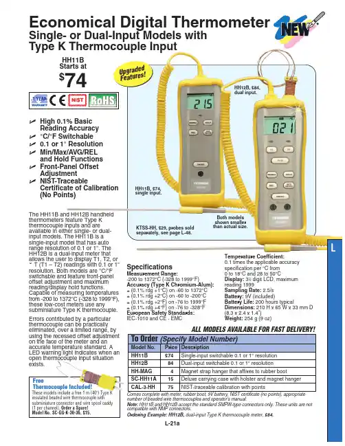
3B SCIENTIFIC ® PHYSICS1Instruction sheet01/18 ALF1 Calorimeter lid2 4-mm sockets3 Stirrer opening4 Plastic nets5 Opening for thermometer6 Lid clamp7 Stirrer8 Heating coil 9 Plastic beaker 10 Calorimeter vesselExperiments are conducted with hot liquid. Cau-tion: danger of burns and scalding!∙ During use, always fasten the calorimeterlid.∙ Set up the experiment on an even surface. ∙ Take extreme care while emptying the calo-rimeter of its contents after conducting the experiment.The calorimeter is made of glass, which is frag-ile and could therefore break and cause injury. ∙ Be careful with the calorimeter vessel.∙ Using the carrier nets, place the calorimetercylinder or other sample types in the glass vessel. Make sure that nothingstrikes the glass vessel.The calorimeter is for determining specific heat capacities, conversion energies of materials, mixing temperatures as well as measurement of electrical equivalents of heat.The equipment consists of a double-walled, heat- insulating plastic container with an insulating vessel inside made of reflecting glass. The lid has openings for a thermometer and the stirring strip. The heating coil has two jacks as contacts, and can be disconnected from the inside of the lid, if needed. Two plastic nets serve for safe loading of samples. The nets remain in the ves-sel during measurements.The calorimeter is supplied with a plastic beaker for protection during transport (see Fig 1).∙ Take out the beaker before using theequipment.3B Scientific GmbH ▪ Rudorffweg 8 ▪ 21031 Hamburg ▪ Germany ▪ Technical amendments are possible © Copyright 2018 3B Scientific GmbH∙If necessary, connect the heating coil to the contacts on the inside of the lid (dependingon the experiment's requirements).Fig 1 Taking out the transport protectionMax. heater voltage: 25 VMax. heating power: approx. 160 W Heat capacity:approx. 200 J/K Contents of insulated container: approx. 1200 ml Dimensions: 240 x 120 mm dia. Weight: approx. 0.8 kgWhen in use, the heating filament must be im-mersed in the water to a depth of at least 2 cm. ∙ Never use the filament in the dry.∙ Experiments should be conducted usingdistilled water.∙ Temperature sensors should not touch thesample (calorimeter cylinder) as this would lead to measurement errors.∙ Stir continuously while performing tempera-ture measurements.∙ After each series of measurements, thecalorimeter and heating filament should be cleaned and dried.5.1 For measuring temperature1 Digital Thermometer, 1 Channel 1002793 Alternatively 1 VinciLab 1021477 1 Thermocouple Type K 10214985.2 For determining specific heat capacity ofsolids1 Set of 4 Calorimeter Cylinders 10032535.3 To power the heater1 DC power supply 20 V, 5 A @230 V 1003312 or1 DC power supply 20 V, 5 A @115 V 10033115.4 To measure time 1 Stopwatch, 15 min 1003369。
扬州市菲柯特电气有限公司XRY-1B氧弹热量计产品使用说明书目录第一章仪器的性能和特点---------------------------------------------------21.1简介------------------------------------------------------------------------21.2主要性能指标------------------------------------------------------------21.3仪器特点------------------------------------------------------------------21.4试验室条件---------------------------------------------------------------3第二章系统结构---------------------------------------------------------------32.1安装示意图---------------------------------------------------------------32.2准备工作------------------------------------------------------------------4第三章系统工作原理---------------------------------------------------------4第四章操作说明---------------------------------------------------------------4第五章发热量(热容量)的测试-----------------------------------------75.1发热量测试准备-------------------------------------------------------75.2 发热量实验步骤------------------------------------------------------85.3 热容量测试--------------------------------------------------------------8第六章常见故障及维护------------------------------------------------------86.1常见故障及原因--------------------------------------------------------86.2日常维护和检查--------------------------------------------------------9附:氧弹热量计装箱单--------------------------------------------------------------10第一章仪器的性能和特点1.1简介XRY-1B型全自动氧弹热量计采用高可靠性真彩智能液晶显示终端,微型热敏打印机,全中文触摸操作操作菜单,界面美观清晰,操作简便直观。
HXHM-20型热能表用户手册(加照片)日照市鸿翔冷暖设备有限公司目录一、HXHM-20型热能表概述二、HXHM-20型热能表原理、基本组成及特点介绍三、HXHM-20型热能表主要技术参数四、HXHM-20型热能表安装使用说明五、保修条款六、产品配臵清单一、HXHM-20型热能表概述HXHM-20 型户用热能表为机电一体化智能型热能计量装臵,该产品克服了国内大多数热量表使用有磁流量传感器的种种弊端,采用无磁流量传感技术,实现对热量的精确计量。
该产品具有外型美观、安装方便、计量准确、运行稳定、抗污防腐能力强、使用寿命长、安全可靠、经济实用等特点,可广泛应用于集中供热、分户计量的采暖设施中。
二、HXHM-20型热能表的原理、基本组成及特点介绍1、原理及组成HXHM-20型热能表用于以热水作为传热媒介的户用采暖系统,计量热水通过进水管和回水管所释放的热量的计量器具。
该产品主要有配对温度传感器、无磁流量传感器和计算器组成。
配对温度传感器测量进水与回水的温度,无磁流量传感器测量流经管道的热水的体积,此两项数据被采集后送至计算器计算出用户使用的热量,并显示出来。
2、主要特点●无磁流量计采用非磁性材料的无磁流量传感器,不受外界磁场干扰,亦不会吸附管道内铁锈和杂质,保证长期使用计量准确;●壳体采用优质黄铜,经硬模铸造、锻造、数控机床和组合机床加工,机械强度好,尺寸精度稳定一致。
轴承部位是唯一的磨损部位,硬质合金轴和人造宝石轴承只能通过特殊工艺才能加工出来,保证了产品长期运行的稳定性和准确性;●配对温度传感器采用德国 Pt1000高精度铂电阻,并臵精密测温电路,保证了高精度的温度测量;●选用了先进的多功能、超低功耗微处理器。
从软、硬件设计两方面采用优化措施,保证计算器长寿命低功耗稳定进行,并有很强的抗电磁干扰能力;●具有自我诊断、故障显示和断电数据保护功能,当热量表偶然出现故障时,显示故障代码并且自动保存当前数据;●具有RS485、M-BUS等多种通讯功能(选配),可实现数据远传、集中控制;●内臵进口环保高能锂电池,工作寿命6年以上(理论计算大于10年);●一体式结构,外形美观,显示器可水平旋转、垂直翻盖,读数方便;单键设计,操作简便;●安装、维护方便,具有防尘、防潮、防水、防拆卸,防止人为破坏等功能。
M L 211H E A T I N G C O U N T E RWarranty conditions are available on this website: MEASURING OF 5 VARIABLES: CAPACITY, ENERGY, INPUT TEMPERATURE, OUTPUT TEMPERATURE, T; N° 2 INPUTS ADDED FROM PT 100 (FROM PT 500 OR PT 1000 IF REQUIRED); BIDIRECTIONAL MEASURE (FOR CALORIES or FRIGORIES); 2 ENERGY TOTALIZERSML 211INDEXTECHNICAL DATA (3)OVERALL FEATURES (3)STANDARD FEATURES (3)OPTIONAL FEATURES (4)ACCURACY (4)OVERALL DIMENSIONS (5)VISUALIZATION PAGE (6)ELECTRICAL CONNECTIONS (7)FUNCTION (9)ACCURACY TABLE (11)HOW TO ORDER (12)ML 211ML 211Power Supply/Consumption ❑18-45V~ (25 VA) 44-66Hz❑18-45 V (20W);❑10-35V (20W)❑N°2 , 1250 Hz, 100mA, 40 VdcML 211ML 211Different visualisation possibilities with the simple press of a keyML 211ML 211ML 2111.1 Insert ND of sensor (0-3000 mm)1.2 Sensor calibration data, visualized on sensor's label1.3 Type of sensor: Enter the first two characters of the serial number of the sensor1.4 Position for insertion sensors: 0=1/8DN, 1=1/2DN, 2=7/8DN1.5 Factory parameters1.6 Length of the cable connecting the sensor to the converter1.7 Enables the empty pipe detection feature1.9 Value of empty pipe sensibility detection1.10* Enables the automatic zero calibration system1.8* Electrodes cleaning2.1* Full scale value set for range N.12.2* Full scale value set for for termal power2.3* Unit of measure and number of decimal totalizes2.4* Unit of measure and number of thermal energy2.5* Pulse value on channel 12.7* Duration of the pulse generated on channel 12.8* Duration of the pulse generated on channel 22.9 Full scale freq. for channel 1 (0.1Hz-1000.0Hz) (0.1Hz-10000Hz con modulo opt.)2.10 Full scale freq. for channel 2 (0.1Hz-1000.0Hz) (0.1Hz-10000Hz con modulo opt.)2.11 Full scale value setting of delta T in °C or °F (0°C */ +250°C - +32°F / +482°F)2.12 Full scale value setting temperature in °C or °F (0°C */ +250°C - +32°F / 442°F)2.13*Value of pressure in T1 point2.14*Value of pressure in T2 point2.15 Enable/disable the selection of mass units on full scale set2.16 To work at temperature < of 0°C2.6* Pulse value on channel 23.1* Measure filter3.2 Low flow zero threshold: 0-25% of full scale value3.4* Point of sensor position3.5 Enable every hour an internal cycle of calibration. The measure it's stopped for 8-15 sec.3.3* Cut-off off delta T4.1 Maximum flow rate alarm. Express in % of full scale. Value =0: alarm disabled4.2 Minimum flow rate alarm. Express in % of full scale. Value =0: alarm disabled4.3 Maximum power alarm. Express in % of full scale. Value =0: alarm disabled4.4 Minimum power alarm. Express in % of full scale. Value =0: alarm disabled4.5 Maximum delta T alarm. Value =0: alarm disabled4.7 Maximum temperature on point T1 Value =0: alarm disabled4.8 Minimum temperature on point T1 =0: alarm disabled4.9 Maximum temperature on point T2. Value =0: alarm disabled4.6 Minimum delta T alarm. Value =0: alarm disabled4.11 Hysteresis threshold set for the minimum and maximum flow rate alarms4.12*Current output value in case of failure4.10 Minimum temperature on point T2. Value =0: alarm disabled4.13*Frequency output value in case of failure5.1* Total direct (positive) flow totalise reset enable5.2* Partial direct (positive) flow totalizer energy reset enable5.3* Total reverse (negative) flow totalise reset enable5.4* Partial reverse (negative) flow totalise energy reset enable5.7* Autozero calibration external command5.8* Functions assigned to input 25.5 Totalizers counting lock command (see page 12)5.6* Block measures commandF U N C T I O N( Note : all page number references are to the operating manual)ML 2119.1* Date and time set9.2 Automatic data logger enable9.4 Displaying of the data stored in the data logger9.5 Displaying of the last 64 alarms stored in the data logger9.6 Visualization function of minimum and maximum peak of flow rate 9.3 Interval time for the data logging function: 1, 2, 3, 6, 8, 12, 24, 48 hours 9.8 Reset all alarm events9.9 Reset all minimum and maximum peak of flow rate stored9.7 Logged data cancel function 6.1* Output 1 functions 6.2* Output 2 functions 6.3* Output 3 functions6.4* Choice of the function and the range of current output n.16.6* Choice of the function and the range of current output n.26.7* Variable to assign at the current output 26.5* Variable to assign at the current output 17.1 Choice of the communication protocol for the IF2 device7.4 Address value of converter (range 0 - 255)7.2 Speed of the RS485 output (possible choices: 2400, 9600, 19200, 38400 bps)7.5 Address of a further converter connected like a terminal7.6 Start remote connection to the terminal. Connection interrupted after 10sec. of inactivity7.3 Instrument answer delay8.1 Choice of the language: E= English, I=italian, F= French, S= Spanish 8.2 Updating frequency on the display: 1-2-5-10 Hz 8.3* Display contrast8.4 Date and time visualization with data logger enable 8.5 Quick start menu visualization 8.10 Reset the processor of the display (useful in case of particular badly operations of the display)8.6 Enable currency function8.8* Value of conversion/currency for direct totalizer 8.9* Value of conversion/currency for reverse totalizer8.7 Choice of the numbers of decimals for the visualization currency value: From 0 to 3.8.11 Total direct (positive) Volume totalizer reset 8.12 Total direct (positive) Energy totalizer reset 8.13 Total direct (negative) Volume totalizer reset 8.14 Total direct (negative) Energy totalizer reset10.2* Converter autotest10.3* Flow rate simulation enabling 10.1* Enable the calibration of the converter 10.4 Firmware revision/version11.1 Level 2 access code enter 11.3 Load user data saved 11.4 Save user data11.2 Load factory data pre-set 11.6 Ks Coefficient11.5 Ignore the calibration error during the switch on test 11.8 Annul the previous function11.7 Delete the offset beetwen T1 an T2ML 211 Array The Manufacturer Guarantee Only English Text Page 11 of 12 ML211_EN_DS019REV03_ISAvailable on our web site: ML 211Production / stock 35044 Montagnana – PD Via Piemonte,2。
3B SCIENTIFIC ® PHYSICS1Instrucciones de uso01/18 ALF1 Tapa del calorímetro2 Casquillos de 4 mm3 Apertura para el agitador4 Redecillas de plástico5 Apertura para el termómetro6 Soporte de la tapa7 Agitador8Filamento calorífico 9 Vaso de plástico 10 Vaso del calorímetroLos experimentos se realizan con líquidos calientes ¡Peligro de quemaduras y escaldaduras!∙ Al trabajar se fija siempre la tapa delcalorímetro con su correspondiente soporte. ∙ Los experimentos se montan sobre unasuperficie plana.∙ ¡Tener cuidado al vaciar el recipientedespués de concluir el experimento!El vaso del calorímetro está hecho de un material vidrioso muy frágil. ¡Se corre el peligro de ruptura y lesiones!∙ ¡Se maneja el vaso del calorímetro consumo cuidado!∙ Introduzca el cilindro calorímetro u otrocuerpo de prueba en el recipiente de vidrio utilizando las redecillas como soporte. Tenga cuidadode que estas no golpeen el recipiente.El calorímetro sirve para la determinación de, capacidades caloríficas específicas, energías de conversión de sustancias, temperaturas de mezclas, así como para medir el equivalente eléctrico del calor.El aparato se compone de un vaso de termo de plástico, de pared doble que lleva insertado un recipiente aislado térmicamente hecho de vidrio especular. En la tapa se encuentran aperturas para introducir un termómetro o el agitador. El filamento calefactor tiene contactos a través de dos casquillos y, dado el caso, se puede retirar desde el lado interior de la cubierta. Dos redecil-las de plástico sirven para la introducción de cuerpos de prueba. Durante las mediciones, las redecillas permanecen en el recipiente.El calorímetro se entrega con un vaso de plástico como protección para el transporte (ver fig. 1). ∙ Antes el uso se retira el vaso.3B Scientific GmbH ▪ Rudorffweg 8 ▪ 21031 Hamburgo ▪ Alemania ▪ Nos reservamos el derecho a cambios técnicos© Copyright 2018 3B Scientific GmbH∙Dado el caso, inserte el filamento calefactor en los contactos de la parte interior de la cubierta (en función de las necesidades delexperimento).Fig 1 Retiro de la protección para el transporteMax. tensión de calentamiento: 25 VMax. potencia de calentamiento:aprox. 160 W Capacidad calorífica : aprox. 200 J/K Contenido del recipiente aislado: aprox. 1200 mlDimensiones: 240 mm x 120 mm Ø Masa: aprox. 0,8 kgDurante el trabajo la espiral de calentamiento debe estar sumergida por lo menos 2 cm en el agua.∙ Nunca trabaje con la espiral decalentamiento en seco.∙ Realice los experimentos con aguadestilada.∙ Los sensores de temperatura no se debenapoyar (fallos de medición) en los cuerpos de prueba (cilindro calorímetro).∙ Las mediciones de temperatura se llevan acabo bajo la constante agitación del medio. ∙ Después de una serie de mediciones selimpia y se seca el calorímetro y lacalefacción.5.1 Para mediciones de temperatura 1 Termómetro digital, 1 canal 1002793 (como alternativa) 1 VinciLab 1021477 1 Termoelemento del tipo K 10214985.2 Para determinar la capacidad caloríficaespecífica de sólidos1 Juego de 4 cilindros calorimétricos 10032535.3 Para el trabajo de la calefacción 1 Fuente de alimentación de CC 20 V, 5 A @230 V 1003312 o1 Fuente de alimentación de CC 20 V, 5 A @115 V 10033115.4 Para mediciones de tiempo 1 Cronómetro mecánico, 15 min 1003369。
电子热量计操作步骤说明书一、引言电子热量计,是一种用于测量热量传输的仪器。
它基于能量守恒的原理,通过测量流体的流速和温度差,计算出热量的传递情况。
本操作步骤说明书旨在详细介绍电子热量计的操作流程,以确保用户正确、高效地使用该设备。
二、准备工作1. 确认所需的设备和材料已准备充分,包括电子热量计、温度传感器、流量计等。
2. 检查设备和材料的完好性,确保没有损坏或缺失。
3. 保证操作环境安全、整洁,并具备所需的电源和通讯连接条件。
三、设备连接1. 将电子热量计的电源线插入电源插座,并确保电源正常接通。
2. 若需要与计算机或其他设备进行数据传输,根据设备说明书进行通讯线的连接。
3. 连接温度传感器和流量计,确保连接端口正确无误并牢固可靠。
4. 仔细检查设备连接情况,避免接线错误引起的问题。
四、系统启动1. 按下电子热量计的电源开关,待系统自检完成后,仪器将进入待机状态。
2. 按照设备说明书,输入所需的系统设置参数,包括温度单位、流量单位、采样时间间隔等。
3. 确认设置参数正确后,启动电子热量计,使其进入工作状态。
五、数据采集1. 在电子热量计界面输入所需的测试参数,包括流速范围、温度范围、采样时间等。
2. 开始数据采集前,确保流体已经达到稳定状态,并记录初始温度和流速值。
3. 按下数据采集按钮,电子热量计将自动记录并计算出热量传递情况。
4. 实时监测数据采集过程中的温度和流速变化,确保数据准确可靠。
六、数据分析1. 数据采集完成后,电子热量计将自动生成数据报告,包括热量传输曲线、温度变化曲线等。
2. 基于数据报告,进行热量计算和分析,根据实际需求得出相应结论。
3. 如需进一步处理数据,将数据导出至计算机,并使用相应的数据分析软件进行处理。
七、设备维护1. 每次使用结束后,将电子热量计恢复至待机状态,并拔掉电源线。
2. 定期对设备进行清洁和维护,包括清理传感器、校准仪器等。
3. 如发现设备故障或异常情况,及时联系设备供应商或维修人员进行处理。