XMC4000中文参考手册-第09章 窗口看门狗定时器(WDT)
- 格式:pdf
- 大小:468.22 KB
- 文档页数:17
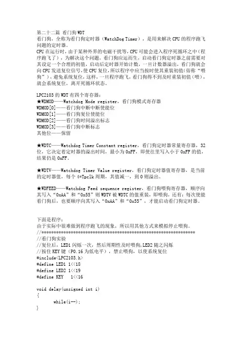
第二十二篇看门狗WDT看门狗,全称为看门狗定时器(WatchDog Timer),是用来解决CPU的程序跑飞问题的定时器。
CPU在运行时,由于某种外界的电磁干扰等,CPU可能会进入程序死循环之中(程序跑飞了),为解决这个问题,看门狗应运而生,启动看门狗定时器之前需要对其设定一个合理的初值,启动后定时器开始计数,一旦计数器溢出,看门狗就会向CPU发送复位信号,使CPU复位,所以程序中应当按时使其重装初值(俗称“喂狗”),避免系统复位,这样,一旦程序跑飞,看门狗得不到及时重装初值(喂),就会系统复位,离开死循环状态。
LPC2103的WDT有四个寄存器:★WDMOD——Watchdog Mode register,看门狗模式寄存器WDMOD[0]——看门狗中断中断使能位WDMOD[1]——看门狗复位使能位WDMOD[2]——看门狗时间溢出标志WDMOD[3]——看门狗中断标志其他位——保留★WDTC——Watchdog Timer Constant register,看门狗定时器常量寄存器,32位,它决定着定时器的溢出时间,最小为0xFF,即使往里写入小于0xFF的值,结果仍是0xFF。
★W DTV——Watchdog Timer Value register,看门狗定时器值寄存器,是当前的定时器值,每个4*Tpclk周期,其值减一,到0则溢出。
★WDFEED——Watchdog Feed sequence register,看门狗喂狗寄存器,顺序向其写入“0xAA”和“0x55”则WDTV被WDTC的值重装,即喂狗,还有:每次使能看门狗后,也要顺序向其写入“0xAA”和“0x55”,才能启动看门狗定时器。
下面是程序:由于实际中很难做到程序跑飞的现象,所以用其他方式来模拟停止喂狗。
//***************************************************************//看门狗实验//复位后,LED1闪烁一次,然后周期性及时喂狗,LED2随之闪烁//按住KEY键(P0.16为低电平),禁止喂狗,以使系统复位#include<LPC2103.h>#define LED1 1<<18#define LED2 1<<19#define KEY 1<<16void delay(unsigned int i){while(i--);}int main(){IODIR=LED1; // LED1设定为输出引脚IOCLR=LED1;delay(3000000); //LED1闪烁一次IOSET=LED1;WDMOD=0X3; //看门狗使能并允许复位WDTC=600000; //看门狗常数(最大不喂狗时间间隔),T=Tpclk*4*WDTCWDFEED=0XAA; //第一次喂狗(0XAA,0X55)启动看门狗WDFEED=0X55;while(1){while((IOPIN&(KEY))==0); //如果该按键被按住(低电平),则程序停在这里IODIR=LED2; // LED2设定为输出引脚IOSET=LED2;delay(300000); //LED2闪烁IOCLR=LED2;delay(300000);WDFEED=0XAA; //按时喂狗WDFEED=0X55;}}//***************************************************************仿真结果:复位后LED1闪烁一次(表明刚复位过),然后LED2闪烁(表明正常喂狗),按住KEY(停止喂狗),LED2不闪烁,LED1闪烁(表明不断复位)。
Hexagon Application Kit For XMC4000 FamilyAUT_ISO-V1Automation I/O CardBoard User's Manual Revision 1.0, 2012-02-28Edition 2012-02-28Published byInfineon Technologies AG81726 Munich, Germany© 2012 Infineon Technologies AGAll Rights Reserved.Legal DisclaimerThe information given in this document shall in no event be regarded as a guarantee of conditions or characteristics. With respect to any examples or hints given herein, any typical values stated herein and/or any information regarding the application of the device, Infineon Technologies hereby disclaims any and all warranties and liabilities of any kind, including without limitation, warranties of non-infringement of intellectual property rights of any third party.InformationFor further information on technology, delivery terms and conditions and prices, please contact the nearest Infineon Technologies Office ().WarningsDue to technical requirements, components may contain dangerous substances. For information on the types in question, please contact the nearest Infineon Technologies Office.Infineon Technologies components may be used in life-support devices or systems only with the express written approval of Infineon Technologies, if a failure of such components can reasonably be expected to cause the failure of that life-support device or system or to affect the safety or effectiveness of that device or system. Life support devices or systems are intended to be implanted in the human body or to support and/or maintain and sustain and/or protect human life. If they fail, it is reasonable to assume that the health of the user or otherTrademarks of Infineon Technologies AGAURIX™, C166™, CanPAK™, CIPOS™, CIPURSE™, EconoPACK™, CoolMOS™, CoolSET™, CORECONTROL™, CROSSAVE™, DAVE™, EasyPIM™, EconoBRIDGE™, EconoDUAL™, EconoPIM™, EiceDRIVER™, eupec™, FCOS™, HITFET™, HybridPACK™, I²RF™, ISOFACE™, IsoPACK™, MIPAQ™, ModSTACK™,my-d™, NovalithIC™, OptiMOS™, ORIGA™, PRIMARION™, PrimePACK™, PrimeSTACK™, PRO-SIL™, PROFET™, RASIC™, ReverSave™, SatRIC™, SIEGET™, SINDRION™, SIPMOS™, SmartLEWIS™, SOLID FLASH™, TEMPFET™, thinQ!™, TRENCHSTOP™, TriCore™.Other TrademarksAdvance Design System™ (ADS) of Agilent Technologies, AMBA™, ARM™, MULTI-ICE™, KEIL™, PRIMECELL™, REALVIEW™, THUMB™, µVision™ of ARM Limited, UK. AUTOSAR™ is licensed by AUTOSAR development partnership. Bluetooth™ of Bluetooth SIG Inc. CAT-iq™ of DECT Foru m. COLOSSUS™, FirstGPS™ of Trimble Navigation Ltd. EMV™ of EMVCo, LLC (Visa Holdings Inc.). EPCOS™ of Epcos AG. FLEXGO™ of Microsoft Corporation. FlexRay™ is licensed by FlexRay Consortium. HYPERTERMINAL™ of Hilgraeve Incorporated. IEC™ of Commission Electrotechnique Internationale. IrDA™ of Infrared Data Association Corporation. ISO™ of INTERNATIONAL ORGANIZATION FOR STANDARDIZATION. MATLAB™ of MathWorks, Inc. MAXIM™ of Maxim Integrated Products, Inc. MICROTEC™, NUCLEUS™ of Mentor Graphics Corporation. Mifare™ of NXP. MIPI™ of MIPI Alliance, Inc. MIPS™ of MIPS Technologies, Inc., USA. muRata™ of MURATA MANUFACTURING CO., MICROWAVE OFFICE™ (MWO) of Applied Wave Research Inc., OmniVision™ of OmniVision Technologies, Inc. Openwave™ Openwave Systems Inc. RED HAT™ Red Hat, Inc. RFMD™ RF Micro Devices, Inc. SIRIUS™ of Sirius Satellite Radio Inc. SOLARIS™ of Sun Microsystems, Inc. SPANSION™ of Spansion LLC Ltd. Symbian™ of Symbian Software Limited. TAIYO YUDEN™ of Taiyo Yuden Co. TEAKLITE™ of CEVA, Inc. TEKTRONIX™ of Tektronix Inc. TOKO™ of TOKO KABUSHIKI KAISHA TA. UNIX™ of X/Open Company Limited. VERILOG™, PALLADIUM™ of Cadence Design Systems, Inc. VLYNQ™ of Texas Instruments Incorporated. VXWORKS™, WIND RIVER™ of WIND RIVER SYSTEMS, INC. ZETEX™ of Diodes Zetex Limited.Last Trademarks Update 2011-02-24Table of ContentsTable of Contents1Overview (7)1.1Key Features (7)1.2Block Diagram (8)2Hardware Description (8)2.1ISOFACE OUT (9)2.2ISOFACE IN (9)2.3IO Expander (10)2.4Power (11)2.5Satellite Connector (12)3Production Data (13)3.1Schematics (13)3.2Layout and Geometry (16)3.3Bill of Material (17)List of FiguresFigure 1Automation I/O Card (AUT_ISO-V1) (8)Figure 2Automation I/O Card Interfaces (8)Figure 3Power Circuit (11)Figure 4ACT Satellite Connector (12)Figure 5Satellite Connector Type ACT (12)Figure 6Satellite Connector, IO Expander, Power (14)Figure 7ISOFACE (15)Figure 8Automation I/O Card Layout (16)List of TablesTable 1ISOFACE OUT Connector Pinout (9)Table 2ISOFACE OUT signal connection to the Satellite Connector (9)Table 3ISOFACE IN Connector Pinout (9)Table 4ISOFACE IN signal connection to the Satellite Connector (10)Table 5GPIO channel LED/SMD pad mapping (10)Table 6IO Expander I2C signal connection to the Satellite Connector (10)Table 7Power LED’s (11)Table 8PowerScale Jumper (11)Table 9Automation I/O Card BOM (17)OverviewIntroductionThis document describes the features and hardware details of the Automation I/O Card (AUT_ISO-V1) designed to work with Infineon’s XMC4500 CPU board. This board is part of Infineon’s Hexagon Application Kits.1 OverviewThe AUT_ISO-V1 board is an application expansion satellite card of the Hexagon Application Kits. The satellite card along with a CPU board (e.g. CPU_45A-V2 board) demonstrates ISOFACE capabilities together with XMC4500. The focus is safe operation under evaluation conditions. The satellite card is not cost optimized and cannot be seen as reference design.1.1 Key FeaturesThe AUT_ISO-V1 satellite card is equipped with following featuresConnection to CPU board (e.g. CPU_45A-V2) via satellite connector ACTISOFACE OUT, up to 8 channelsISOFACE IN, up to 8 channelsI2C based IO expander up to 8 channelsPower supplyo Powerjack for external 24 V supplyo From CPU board via ACT satellite connector1.2Block DiagramFigure 1 shows the block diagram of the AUT_ISO-V1 satellite card. There are following building blocks:Figure 1Automation I/O Card (AUT_ISO-V1)2 Hardware DescriptionThe following sections give a detailed description of the hardware and how it can be used.Figure 2 Automation I/O Card InterfacesISOFACE OUT (ISO1H812G)ISOFACE IN (ISO1I811T)Power 3.3 V (IFX1763SJV33)ISOFACE IN ConnectorACT Satellite ConnectorPower Jack24 V2.1 ISOFACE OUTISOFACE output device used in AUT_ISO-V1 satellite card is ISO1H812G. It is supplied by VDD3.3 on the CPU side and VDD24 for the ISOFACE OUT side. VDD24 and GNDISO can to be connected either by X300 or by X240(24 V external power jack). This is the same net that supplies the DC/DC converter. VDD24 is +24 Vdc (referred to GNDISO)Table 1 below gives the signal details of ISOFACE OUT connector.Table 12 below gives the details of SPI signal connection to the satellite connector.2.2 ISOFACE INISOFACE input device used in AUT_ISO-V1 satellite card is ISO1I811T. It is supplied by 3.3 V on the CPU side and VBB (24V) for the ISOFACE IN side. VBB and GNDBB need a separate connection to 24 V external power source through connector X320.Resistor R337 is used on board for setting input type to IEC61131-2 Type 1.Resistors R326 and R327 sets the frequency of ISOFACE IN to 100 kHz (default).Table 3 gives the details of ISOFACE IN connector pin mapping.Table 3 ISOFACE IN Connector PinoutISOFACE IN shares the same SPI lines with ISOFACE OUT except the chip select as shown in Table 4.2.3 IO ExpanderThe AUT_ISO-V1 satellite card supports GPIO expansion though I2C IO-Expander on board (U230). The I2C Address for IO expander device is 0x1001000X. The satellite card supports 8 such GPIO’s. All t he GPIO’s are connected to LEDs (V230-V237) and SMD-Pads (TP230 – TP237). The Table 5 gives the GPIO channel and corresponding LED/PAD mapping.Table 6 shows the connection of the IO Expander device to the ACT satellite connector.2.4 PowerThe AUT_ISO-V1 satellite card can be supplied by an external power supply (24 V / 1 A) to be connected to the power jack X240 or by a 5 V supply via the 80-pin ACT satellite connector. An external power supply is necessary only in case the current coming via the ACT satellite connector is not sufficient.A DC-DC converter on board (U240) steps down the input voltage from the power jack X240 to 5 V (VDD5). The input voltage can be in the range from 12 V to 24 V. An on board linear voltage regulator is generating a 3.3 V (VDD3.3) power supply out of the VDD5.Figure 3 Power CircuitA Diode V242 protects the reverse flow of current to an external source. Therefore a simultaneous power supply of the satellite boards via both the power jack and the satellite connector with not harm.LED V210 indicates the presence of 5 V power and LED V211 indicates the presence of 3.3 V power.Table 7 Power LED’sThe AUT_ISO-V1 satellite card supports a PowerScale probe for power measurement purpose.Table 8 PowerScale Jumper2.5 Satellite ConnectorThe satellite connector of the AUT_ISO-V1 satellite card interfaces it’s the signals to a CPU board e.g. CPU_45A-V2. Take care to connect the ACT satellite card always to the corresponding ACT satellite connector of the CPU board only.Figure 4 ACT Satellite ConnectorThe signal mapping of the ACT satellite connector and correponding CPU function are provided in figure 6Figure 5 Satellite Connector Type ACT3 Production Data3.1 SchematicsThis chapter contains the schematics for the Automation I/O Card:Satellite Connector, IO Expander, PowerISOFACEFigure 6 Satellite Connector, IO Expander, PowerFigure 7 ISOFACE3.2 Layout and GeometryFigure 8 Automation I/O Card Layout3.3 Bill of MaterialTable 9 Automation I/O Card BOMTable 9 Automation I/O Card BOMw w w.i n f i n e o n.c o mMouser ElectronicsAuthorized DistributorClick to View Pricing, Inventory, Delivery & Lifecycle Information:I nfineon:KIT_XMC4x_AUT_ISO-001。

WDT是英语Watchdog Timer的缩写字母。
Watchdog Timer 中文名看门狗。
是一个定时器电路, 一般有一个输入,叫喂狗,一个输出到MCU的RST端,MCU正常工作的时候,每隔一段时间输出一个信号到喂狗端,给WDT 清零,如果超过规定的时间不喂狗,(一般在程序跑飞时),WDT 定时超过,就回给出一个复位信号到MCU,使MCU复位. 防止MCU死机. 看门狗的作用就是防止程序发生死循环,或者说程序跑飞。
工作原理:在系统运行以后也就启动了看门狗的计数器,看门狗就开始自动计数,如果到了一定的时间还不去清看门狗,那么看门狗计数器就会溢出从而引起看门狗中断,造成系统复位。
所以在使用有看门狗的芯片时要注意清看门狗。
硬件看门狗是利用了一个定时器,来监控主程序的运行,也就是说在主程序的运行过程中,我们要在定时时间到之前对定时器进行复位如果出现死循环,或者说PC指针不能回来。
那么定时时间到后就会使单片机复位。
常用的WDT芯片如MAX813 ,5045, IMP 813等,价格4~10元不等. 软件看门狗技术的原理和这差不多,只不过是用软件的方法实现,我们还是以51系列来讲,我们知道在51单片机中有两个定时器,我们就可以用这两个定时器来对主程序的运行进行监控。
我们可以对T0设定一定的定时时间,当产生定时中断的时候对一个变量进行赋值,而这个变量在主程序运行的开始已经有了一个初值,在这里我们要设定的定时值要小于主程序的运行时间,这样在主程序的尾部对变量的值进行判断,如果值发生了预期的变化,就说明T0中断正常,如果没有发生变化则使程序复位。
对于T1我们用来监控主程序的运行,我们给T1设定一定的定时时间,在主程序中对其进行复位,如果不能在一定的时间里对其进行复位,T1 的定时中断就会使单片机复位。
在这里T1的定时时间要设的大于主程序的运行时间,给主程序留有一定的的裕量。
而T1的中断正常与否我们再由T0定时中断子程序来监视。

网络视频监控软件-4000操作说明目录一设备管理1.1 列表树配置 41.2 添加设备的操作 51.3 通道的配置 8二图像预览2.1非轮循预览 92.2按节点播放 92.3结束播放 10三云台控制3.1 485参数设置 113.2 云台控制 123.3 方向控制 12四录像和回放4.1 录像 134.2 客户端本地录像 134.3 集中存储服务器录像配置 144.4 NVR服务器的添加 14五维护管理5.1 本地配置 155.2 日志管理 165.3 日志查询 165.4 用户管理 185.5 用户的添加、删除 19一设备管理使用软件进行操作前,需要先对设备进行添加和配置操作。
点击标签栏标签进入配置模式,点击右侧导航栏“设备管理”项即可进入设备管理的界面。
1.1 列表树配置软件初始运行时,列表树里默认为空,右键点击列表树任意空白处可进行区域的添加。
在区域名称栏中填写名称后点击确定即可向列表树中添加一个区域,并且由于本次添加的区域为首个区域,因此该区域不存在上级区域,因此上级区域名称栏中为空。
区域添加完成后,右键点击区域节点,可选择进行子区域、设备和流媒体的添加操作。
注:区域名称中头尾的换行、空格、TAB字符将被自动去除。
区域名称不能为空,不能含有字符“%”、“'”和“%”(不包含左右引号“和”)。
注:添加了一个区域后,该区域自动进入选中状态,此时在列表树中的空白区域右键点击无效。
中性发布版最多支持50个区域。
注意:如果删除区域下包含有其他区域、流媒体、设备或者通道,则删除操作不仅会删除选中的区域,而且会删除该区域下所有的区域、流媒体、设备或者通道;若该区域下有通道正在预览或录像,将会给出警告信息。
右键点击添加的区域,弹出区域管理菜单。
选择“添加区域”,可进行子区域的添加。
选择“删除节点”将删除处于选中状态下的区域。
双击选中的区域节点,弹出“修改区域信息”菜单,可进行区域名称的修改。
1.2 添加设备的操作右键点击添加的区域,弹出区域管理菜单,选择“添加设备”。
看门狗说明1、看门狗原理主板上提供一个可按分或秒计时的,最长达255级的可编程看门狗定时器,WDT超时事件发生时系统复位。
本程序(w83627hf_wdt.c)是基于Winbond83627芯片的看门狗驱动程序。
2、驱动程序接口●wdt_open :打开设备,应用程序调用open时进入该函数。
●wdt_close :关闭设备,应用程序调用close时进入该函数●wdt_write :写设备,若传入数据大小不为0则喂狗;应用程序调用write时进入该函数。
●wdt_ioctl :应用程序调用ioctl时进入该函数,通过传入不同的参数实现不同的功能。
主要参数如下:WDIOC_GETSUPPORT :获取看门狗信息watchdog_info(见w83627hf_wdt.h) WDIOC_KEEPALIVE :喂狗,同write函数功能类似WDIOC_SETTIMEOUT :设置超时值WDIOC_GETTIMEOUT :获取超时值WDIOC_SETOPTIONS :设置看门狗状态,开启(WDIOS_ENABLECARD)或关闭(WDIOS_DISABLECARD)3、应用程序编写主要步骤如下(请参考代码w83627hf_test.c):●打开设备调用open方法,返回值为已打开的设备,若小于0表示打开失败,以下的调用都要用该返回值做参数,表示操作该设备。
wdt = open(WDT_DEVICE, O_RDWR);●开启看门狗调用ioctl方法,传入WDIOC_SETOPTIONS参数,设置开启(WDIOS_ENABLECARD)状态,方法如下:ioctl(wdt, WDIOC_SETOPTIONS, WDIOS_ENABLECARD);●设置看门狗超时值(可选,默认为60s)调用ioctl方法,传入WDIOC_SETTIMEOUT参数,设置指定的超时值。
ioctl(wdt, WDIOC_SETTIMEOUT, &timeout);//timeout为超时值●喂狗一般用while(1)循环在超时时间(timeout)内定时喂狗,若在timeout内没喂狗,则系统复位。
WDT:(Watch Dog Timer)看门狗定时器,简写WDT,主要有一个专用的定时器组成,当启动看门狗后,定时器开始计数,计数满后将产生一个中断,复位单片机。
作用:单片机很容易收到外界的干扰,如电源电压波动,电机起停,受到干扰后,程序有可能跑飞,不按原来的逻辑顺序执行,跳到另一地方执行,或者陷入一个死循环。
启用看门狗后,如果在设定的定时时间内没有执行清0看门狗定时器的指令,单片机将复位,回到程序的开始处,重新开始执行程序,保证系统的正常运行。
WDE为"1“ 时,看门狗使能,否则看门狗将被禁止。
只有在WDTOE为"1“ 时WDE 才能清
零。
以下为关闭看门狗的步骤:
1. 在同一个指令内对WDTOE 和WDE 写"1“,即使WDE 已经为"1“
2. 在紧接的4 个时钟周期之内对WDE 写"0”
步骤如下:
一、启动看门狗:WDTCR|=(1<<WDTOE)|(1<<WDE);
二、禁止看门狗:WDTCR=0X00; //再次启动看门狗必须先禁止看门狗,
三、WDTCR|=(1<<WDTOE)|(1<<WDE)|(1<<WDP2)|(1<<WDP1)|(1<<WDP0); //看门狗定时时间1S
在1s内重复执行上述指令,清0看门狗。
小企鹅diy 科学探究学习网
更多文章转到/wqb_lmkj/blog文章分类单片机。
学习之6---看门狗定时器(WDT)//PIC.H中定义了宏#define CLRWDT() asm("clrwdt")因此在PICC的c语言中可以直接使用CLRWDT()对WDT清0//若单片机WDT使能,在适当位置加入CLRWDT(),程序进入正常运行时,每隔一定时间均会执行CLRWDT()语句对WDT清0,芯片不会复位//如果程序陷入死循环,不会执行到CLRWDT()语句,则超出所设定的时间后,WDT溢出使芯片复位,从头(000H)开始执行,单片机恢复正常运行//PIC16F单片机,看门狗定时器的启用只能在芯片的烧写时确定,即无法用软件来开启或关闭WDT,但在PIC16f88X中可以。
//PIC16单片机的WDT基本溢出时间为18MS,由RC充放电时间确定,在-40~85度之间变化时,WDT基本溢出时间在7-33ms变化#include<pic.h>__CONFIG(0X3F3D);//开启WTDvoid DELAY(unsigned int);#define LED1 RB1main(void){TRISB=0B11111101;OPTION=0B11111011; //WDT的分频比为1:8,最大复位时间为18*8=144msif(TO==0)// 若写成T0,则编译出错。
{LED1=1; //看门狗定时器溢出,仿真时溢出TO不会清零}elseLED1=0;while(1){DELAY(100);//模拟一个运行100ms的子程序CLRWDT();DELAY(200);//模拟一个运行200ms的子程序,此时会产生溢出(200ms>144ms)CLRWDT();};}void DELAY(unsigned int n){unsigned int j;char k;for(j=0;j<n;j++)for(k=246;k>0;k--)NOP();}学习之7--EEPROM的读写EEPROM特点:掉电时保持不变,F877A的EEPROM参数是保证1 000 000次擦除,数据保存>40年PICC中定义了读/写EEPROM的宏EERPOM_WRITE(addr,value); EEPROM_READ(addr);//PICC中系统已经为我们定义了读/写EEPROM的宏//宏EEPROM_WRITE写入EEPROM,只是启动写入过程,写完要几MS,当读/写EEPROM 时,程序会自动检测是否还在写,若是,则等待//C程序编写不涉及EECON1,EECON2#include<pic.h>__CONFIG(0X3F39);__EEPROM_DATA(89,34,48,210,53,192,7,57);//初始化EEPROM,分别写入单元0~7main(void){char aa;aa=EEPROM_READ(3);//读EEPROM单元3的内容EEPROM_WRITE(9,0X9A);//将0X9A写入EERPOM的单元9aa=EEPROM_READ(9);//读EEPROM单元9的内容while(1);}。