ZT160-200-250-275零件手册1998
- 格式:pdf
- 大小:2.13 MB
- 文档页数:51
Contents1.SCOPE (2)2.INSTALLATION (2)3.VALVE OPERATION (3)4.DISASSEMBLY (3)5.ASSEMBLY (4)6.REPAIR KITS (5)7.BILL OF MATERIALS (6)1.SCOPE1.1. CAUTION1.1.1. F or your safety, read this manual before installation or service.1.1.2. B efore installing or servicing, please ensure the line pressure has been relieved and any hazardous fluidshave been drained or purged from the system.1.1.3. E nsure that all Lockout and Tagout procedures for the system have been properly implemented.1.2. USE1.2.1. M aximum results and long life of valves can be maintained under normal working conditions and accordingwith pressure/temperature ratings and corrosion data chart.2.INSTALLATION2.1. GENERAL INFORMATION FOR INSTALLATION2.1.1. T he valve can be installed in any position on the pipeline.2.1.2. B efore installation of the valve, the pipe must be flushed clean of dirt, burrs, and welding residue, or theseats and ball surface will be damaged. The pipe must be free from tension and in proper alignment. Checkto ensure that all connections are free from defects.2.2. INSTALLATION OF THREADED VALVES2.2.1. U se conventional sealant, such as hemp core, Teflon, etc. on threads. Apply wrench only on the hexagonof the valve ends. Tightening by using the valve body or lever can seriously damage the valve. In someapplication, screwed valves are back welded on site. These valves must be treated as per instructions forthe weld end valves before back welding.2.3. INSTALLATION OF WELDED ENDS2.3.1. T ack weld the valve on the pipe in four points on both end caps.2.3.2. W ith the valve in the open position, (lever to be parallel to the axis of the pipe), remove all the body boltsexcept one. Loosen the nut on the remaining bolt. Swing the body outside the pipe. Finish welding bothend caps on the pipe.2.3.3.2.3.4. W hen cooled down, clean both end caps and body surface.2.3.5. S wing the body back in position and replace the bolts. Tighten all nuts slightly. This operation is veryimportant to keep the body and end caps perfectly parallel, thus preventing distortion of end caps. Tightenbody bolts evenly (see section 5.5). Make sure that maximum tightening torque is observed. Check properoperation of the valve.3.VALVE OPERATION3.1.MANUAL3.1.1.HANDLE3.1.1.1.To OPEN the valve, turn the handle counterclockwise until the handle is parallel with the pipeline and the handlehas contacted the handle stop.3.1.1.2.To CLOSE the valve, turn the handle clockwise until the handle is perpendicular with the pipeline and the handlehas contacted the handle stop.3.1.1.3.A handle lock is incorporated into the handle. To use, slide the lock into the mounting pad, in the full open orfull closed position. Insert an appropriate size lock or hasp into the handle. If it can be performed safely, try toturn the handle to ensure that the valve has been locked properly.3.1.2.GEAR3.1.2.1.To OPEN the valve, turn the handle wheel counterclockwise. The indicator will be pointing to the open positionand stop rotating when fully opened. The flow can be adjusted by stopping the indicator anywhere between openand close.3.1.2.2.To CLOSE the valve, turn the hand wheel clockwise. The indicator will be pointing to the close position and thehandwheel will stop rotating when fully closed. The flow can be adjusted by stopping the indicator anywherebetween open and close.3.2.AUTOMATED3.2.1.A-T Controls 83/8R Series Ball Valves can be mounted with quarter turn actuators. Valves with actuators shall bechecked for proper valve stem alignment. Angular or linear misalignment may result in high operational torque andunnecessary wear on the valve stem. See the actuator IOM for information on operating the actuator.4.DISASSEMBLYWARNINGCAUTION, FLUIDS CAN BE TRAPPED IN THE BODY OF THE VALVE, POSSIBLY UNDER HIGH PRESSURE. FOR YOUR SAFEY, IT IS IMPORTANT THAT PRECAUTIONS ARETAKEN BEFORE REMOVAL OF THE VALVE FROM THE LINE OR ANY DISASSEMBLY.4.1.Remove actuator or gear if equipped.4.2.Care should be taken to not damage the surface finish of the valve components.4.3.Remove the ends (2) from the body (1) by removing the body bolts (17) and body nuts (18).4.4.Remove the seat (4) and body gaskets (5) from both sides of the body (1). Once removed, with the valve in the fully closedposition, the ball (3) should slide freely out of the body (1).4.5.If equipped, remove the handle nut (13), handle (14), and the handle stop assembly items (16).4.6.While holding the stem (6) stationary, remove the packing nut (21). Once removed, the locking saddle (12), Bellevillewashers (11), and the packing bushing (9) should be free to remove.4.7.While holding the bottom of the stem (6), push the stem (6) through the inside of the valve body (1).4.8.Remove the packing set (8) and the stem seal (7).4.9.Inspect all components for damage and, if necessary, clean or replace.5.ASSEMBLY5.1.Care should be taken to not damage the surface finish of the valve components.5.2.Place stem seal (7) on the stem (6) and install it by going through the body (2). Insert V-style packing set (8) over stem (6),with the V pointing away from the valve (see Bill of Materials for correct orientation).5.3.Install the packing gland (10), the Belleville washers (11), the locking saddle (12), and the packing nut (21). While holdingthe stem (6), tighten the packing nut (21) to the torque listen in the Fastener Torque Chart. Tighten further if needed in order to be able to place the locking saddle (12) over the packing nut (21).5.4.Ensure the stem (6) is in the closed position with the body tang parallel with the flow of the valve. Insert a seat (4) and bodygasket (5) in one side of the body (1). Carefully slide the ball (3) into the body (1) and insert the other seat (4) and body gasket (5).5.5.Assemble ends (2) onto body (1). Insert all body bolts (17) and nuts (18) into valve and tighten to finger tight, making surethat the ends (2) are flat against the body (1). Tighten all body bolts (on both side for valves 2-1/2” thru 4”) from the nut(18) side (if equipped) in a star pattern to 50% of the final torque shown in the Fastener Torque Chart. Using the handle (14)or an adjustable wrench, cycle the valve 3 times. Tighten all body bolts (17) to the final torque in a star pattern. Check each body bolt (17) torque and tighten if needed a final time. It is acceptable for the torque to relax slightly over time due to relaxation of the polymer components, but the valve will still seal properly. If leakage is detected, repeat the steps for tightening the body bolts (17).5.6.If required, assemble the locking device (19), handle stop (16), handle (14), and the handle nut (13).6.REPAIR KITSRepair kits are available to replace all soft goods. See Bill of Materials for components that are included in the repair kits.7.BILL OF MATERIALSA-T Controls product, when properly selected, is designed to perform its intended function safely during its useful life. However, the purchaser or user of A-T Controls products should be aware that A-T Controls products might be used in numerous applications under a wide variety of industrial service conditions. Although A-T Controls can provide general guidelines, it cannot provide specific data and warnings for all possible applications. The purchaser / user must therefore assume the ultimate responsibility for the proper sizing and selection, installation, operation, and maintenance of A-T Controls products. The user should read and understand the installation operation maintenance (IOM) instructions included with the product and train its employees and contractors in the safe use of A-T Controls products in connection with the specific application.While the information and specifications contained in this literature are believed to be accurate, they are supplied for informative purposes only. Because A-T Controls is continually improving and upgrading its product design, the specifications, dimensions and information contained in this literature are subject to change without notice. Should any question arise concerning these specifications, the purchaser/user should contact A-T Controls.For product specifications go to https:///Downloads/A-T Controls, Inc. • 9955 International Boulevard, Cincinnati, OH 45246 • Phone: (513) 530-5175 • Fax: (513) 247-5462 • 。
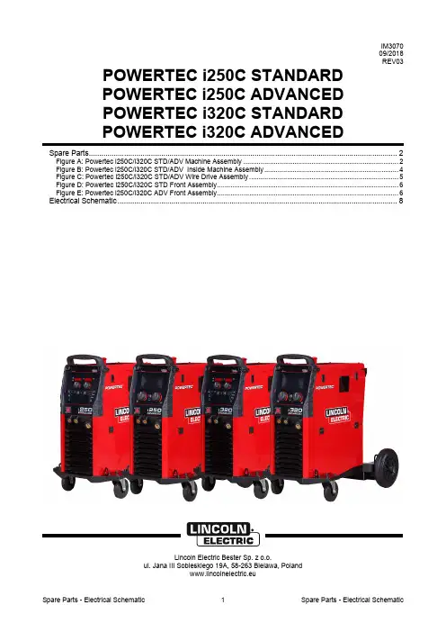
Spare Parts - Electrical Schematic Spare Parts - Electrical Schematic1 IM3070 09/2018 REV03POWERTEC i250C STANDARD POWERTEC i250C ADVANCED POWERTEC i320C STANDARDPOWERTEC i320C ADVANCEDSpare Parts (2)Figure A: Powertec i250C/i320C STD/ADV Machine Assembly .................................................................................. 2 Figure B: Powertec i250C/i320C STD/ADV Inside Machine Assembly ....................................................................... 4 Figure C: Powertec i250C/i320C STD/ADV Wire Drive Assembly ............................................................................... 5 Figure D: Powertec i250C/i320C STD Front Assembly ................................................................................................ 6 Figure E: Powertec i250C/i320C ADV Front Assembly (6)Electrical Schematic (8)Lincoln Electric Bester Sp. z o.o.ul. Jana III Sobieskiego 19A, 58-263 Bielawa, Polandwww.lincolnelectric.euSpare Parts - Electrical Schematic Spare Parts - Electrical Schematic2 Spare PartsSP50430, SP50431, SP50432, SP50433 REV03ASSEMBLY PAGE NAMEP o w e r t e c M a c h i n e A s s e m b l yM a c h i n e F r o n t A s s e m b l y W i r e D r i v e A s s e m b l y & E u r o S o c k e t A s s e m b l yP o w e r t e c i 250C /i 320C S T D F r o n t A s s e m b l y P o w e r t e c i 250C /i 320C A D V F r o n t A s s e m b l y M i s c e l l a n e o u s I t e m s CODE NO.: K NO.: FIGURE NO.:A B C D E - 50430POWERTEC i250C STANDARD 1 1 1 1 - 1 50431 K14157-2 POWERTEC i250C ADVANCED 2 2 2 - 2 2 50432 K14158-1 POWERTEC i320C STANDARD 3 3 3 3 - 3 50433 K14158-2 POWERTEC i320C ADVANCED 444-44Figure A: Powertec i250C/i320C STD/ADV Machine AssemblyItem Description Part Number QTY 1 2 3 4 5 6 CABLE GRD-300A-50-5M 1 x x x x1 WELDING2 SIDE PANEL KIT R-1019-486-1R 1 x x x x3 COVERKIT R-3019-455-1/02R 1 x x x x4 HANDLE R-0010-292-1R 1 x x x x5 BASE, PARTITION, SHELF KIT R-3019-426-1R 1 x x x x6 SIDE COVER KIT R-0010-623-1R 1 x x x x7 FRONT AND REAR PANEL KIT R-8040-387-1R 1 x x x x8 LOCK 0654-610-004R 2 x x x xHINGE 0654-610-007R 2 x x x x9 LEAF10 MAIN INPUT CORD R-5041-497-1R 1 x x x x11 WHEELS 1029-660-127R 2 x x x x12 WHEELS 1029-660-250R 2 x x x xSpare Parts - Electrical Schematic Spare Parts - Electrical Schematic3Spare Parts - Electrical SchematicSpare Parts - Electrical Schematic4Figure B: Powertec i250C/i320C STD/ADV Inside Machine AssemblyItem DescriptionPart NumberQTY 1 2 3 4 5 6 13 TRANSFORMER AND CHOKE R-8040-382-2R 1 x x x x 14 INVERTER BOARD R-6042-079-1R 1 x x x x 15 HALL SENSOR W4900004R 1 x x x x 16 FAN W66X1369R 2 x x x x 17 INPUT FILTER Y051-1R1 x x x x 18 SOLENOID 0972-423-040R 1 x x x x 19 CABLE RELIEF1361-599-674R 1 x x x x 20FUSE SOCKET 1158-632-032R 1 x x x x FUSE 1A 400V 1158-660-003R 1 x x x x 21 PC BOARD R-6042-081-1R 1 x x x x 22 WIRE SPOOL HUB 0744-000-335R 1 x x x x 23 PLASTIC NUT 0744-000-336R 1 x x x x 24 USB SOCKET 1158-641-061R 1 - x - x 25 SWITCH1115-280-004R 1 x x x x 26 THREE PHASE BRIDGE1156-112-206R 1 x x x x 27CONTROL BOARD R-6042-082-2R 1 x - - - CONTROL BOARD R-6042-082-1R 1 - x - - CONTROL BOARD R-6042-080-2R 1 - - x - CONTROL BOARD R-6042-080-1R 1 - - - x 28 OUTPUT BRIDGE R-8040-388-1R 1 x x x x 29 LED MODULE R-5041-508-1R 2x x x xFigure C: Powertec i250C/i320C STD/ADV Wire Drive AssemblyItem Description Part Number QTY 1 2 3 4 5 6 30 WIRE DRIVE MOTOR 1111-722-048R 1 x x x x31 COMPLETE FEED PLATE ASSEMBLY(INCLUDES 1.0/1.2 MM DRIVE ROLLS ANDWIRE GUIDE KIT)0744-000-009R 1 x x x xSpare Parts - Electrical Schematic Spare Parts - Electrical Schematic5Spare Parts - Electrical SchematicSpare Parts - Electrical Schematic6Figure D: Powertec i250C/i320C STD Front AssemblyFigure E: Powertec i250C/i320C ADV Front AssemblyItem Description Part Number QTY 1 2 3 4 5 632 DISPLAY FRONT PANEL KIT R-0010-619-2R 1 x - x -33 USER INTERFACE PCB R-6042-078-1R 1 x - x -34 KNOB 9SM22778-2 2 x - x -35 BUTTON 9SS23055 2 x - x - 1 - x - x36 MAIN SWITCH 1115-270-022R 1 x x x x37 EURO SLEEVE C-1891-006-1R 1 x x x x38 SOCKET W7690350 R 2 x x x x39 PCB R-6042-077-1R 1 - x - x40 DISPLAY FRONT PANEL KIT R-0010-618-2R 1 - x - x41 LCD 0942-177-002R 1 - x - x42 KNOB 9SM22778-3 2 - x - xMiscelaneous Items (not shown in figure A, B, C, D, E)Item Description Part Number QTY 1 2 3 4 5 643 HARNESSES KIT R-5041-494-1R 1 x x x xSpare Parts - Electrical Schematic Spare Parts - Electrical Schematic7Electrical SchematicSpare Parts - Electrical Schematic Spare Parts - Electrical Schematic8234Spare Parts - Electrical Schematic Spare Parts - Electrical Schematic9。

GZSW/技北京国中生物科技有限公司配件装配通用技术条件(初稿)审批:审核:编制:目录1、范围 ........................................ 错误!未定义书签。
2、引用标准 .................................... 错误!未定义书签。
3、基本要求 .................................... 错误!未定义书签。
4、各种连接方法的要求 .......................... 错误!未定义书签。
螺钉、螺栓连接............................. 错误!未定义书签。
销连接...................................... 错误!未定义书签。
键连接..................................... 错误!未定义书签。
过盈连接.................................... 错误!未定义书签。
5、典型部件装配要求 ............................ 错误!未定义书签。
滚动轴承的装配.............................. 错误!未定义书签。
联轴器的装配................................ 错误!未定义书签。
齿轮的装配................................. 错误!未定义书签。
链轮、链条的装配........................... 错误!未定义书签。
带与带轮的装配.............................. 错误!未定义书签。
润滑系统的装配.............................. 错误!未定义书签。
气动系统的装配............................. 错误!未定义书签。
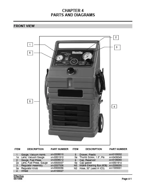
CHAPTER 4PARTS AND DIAGRAMSFRONT VIEWITEM DESCRIPTION PART NUMBER ITEM DESCRIPTION PART NUMBER 1Gauge, Vacuum Asmb.MV20080105Drawer, Plastic MV01050021a Lens, Vacuum Gauge MV0501910 5a Thumb Screw, 1.5”, Pls MV0406049 2Gauge, Fuel Press.MV20080126Cap, Reservoir MV01060602a Lens, Fuel Press. Gauge MV0500007 6a Cap gasket MV0501914 3Regulator Assembly MV2007006NS I ntake C leaning S ys.(ICS)MV20060003a Regulator Knob MV0500056NS Hose, 30” (used in ICS)MV1005001 4Wheel MV0100027CHAPTER 4 PARTS AND DIAGRAMSREAR VIEWITEM DESCRIPTION PART NUMBER ITEM DESCRIPTION PART NUMBER 1Filter, Orange (BT839-10)MV05000953Pump, Assembly MV20080311a Filter Nipple MV0303095 4a Adapter, 90° Bulkhead MV03001314b Adapter, Hex Nipple MV0303092 2Tank Asmb., Reservoir MV20086025Manifold Assemblies See Page 4-4CHAPTER 4 PARTS AND DIAGRAMS SIDE VIEWSITEM DESCRIPTION PART NUMBER ITEM DESCRIPTION PART NUMBER1Hose, Black Return MV20003004Cables, Battery MV02080432Hose, Red Out MV20004005Hanger, Black Metal MV01050043a Connector, QuickDisconnect MV08002306Hose, Vacuum(requires 12 feet)MV0700100(per foot)3b Fitting, 3/8”Cmp x ¼”MPT MV0300020CHAPTER 4 PARTS AND DIAGRAMSMANIFOLD BLOCK ASSEMBLIES and FITTINGSITEM DESCRIPTION PART NUMBER ITEM DESCRIPTION PART NUMBERMV0300015 1Valve, Relief MV05000887Elbow, 5/16”Nt x 1/8”MPT(pump)2Block, Manifold MV03001108Elbow, 5/16”Tb x 1/8”FPT(pressure gauge)MV0300011 3Valve, Solenoid (NC)MV0500018 9Elbow, 5/16”Nt x ¼”FPT(regulator)MV0303092 4Nipple, ¼”MPT x ¼”MPT MV030001410Union,1/4”MPT x ¼”MPT,Zp5Switch, Pressure MV050001611Union, 5/16”Nt x ¼”MPT MV0300017MV03000186Elbow, 5/16”Nt x ¼”MPT(block)CHAPTER 4 PARTS AND DIAGRAMS COMPLETE REPLACEMENT PARTS LISTING:ITEM LEVELS MotorVac Descriptions Qty ASMB Part NumberSUBASMB11N/A CABINET ASSEMBLY1 22MV010-0026Hub Cap2 32MV010-0027Wheel, 8" x 1.75", rubber2 42MV011-0014Hanger Bracket, Stl, painted black3 52MV010-6008Axle, 0.5" Dia., Zinc Plate1 62MV010-5600Cabinet, Red Plastic1 72MV010-5403Drawer Magnet Contact Plate, Stl (2 studs)1 82MV040-0603Snap Bushing, for Vacuum Hose1 92MV040-0604Cap Nut, 1/2"2102MV040-0607Nut, Nylock 1/4"-20, Zp, for hanger6112MV040-0610Screw, PHP 1/4"-20 x 5/8", Zp, for hanger6122MV040-6014Spacer 1/16", Zp4132MV040-6015Tinnerman Nut, #8, to secure back panel9142MV040-6016Kep Nut, 6-32, Zp, for drawer magnet contact plate2152MV040-6049Thumbscrew, 10-32 x 1-1/2", Ny, for drawer retention8A 162MV200-8036Drawer Assemblies (4)1173MV010-5002Drawer, Black plastic4A 183MV040-6024Magnet, 30lbf pull, 3/16" mount4A 193MV040-6025Pop Rivet, Blind Head, 3/16", Al, for magnet4A 203MV040-6051Tinnerman Nut, 10-32, for drawers8A 21221MV200-Return Hose Assembly, Black10300232MV030-0020Un, 3/8"Cmp x 1/4"MPT, Ni1242MV070-0020NAB Hose, 3/8"OD, Blk, Ny10ft 252MV080-0230Female Quick Disconnect, 1/4" x 1/4"FPT, Ni126Output Hose Assembly, Red1271MV200-0400282MV030-0020Un, 3/8"Cmp x 1/4"MPT, Ni1292MV070-0010NAB Hose, 3/8"OD, Red, Ny10ft 302MV080-0230Female Quick Disconnect, 1/4" x 1/4"FPT, Ni131Pump, Tank, Manifold Block,& Filter Assembly1321MV200-8601332MV010-5400Mounting Bracket for pump, tank, manifold block1342MV010-5401Mounting Bracket for filter asmb.1352MV010-5402Mounting Bracket Support, leftside1362MV010-5404Mounting Bracket Support, rightside1372MV020-5320Ferrite Bead, for solenoid wires1382MV040-0019Screw, PHP 10-32 x 3/8",Zp, for filter bracket2392MV040-0200Starwasher, Internal, #6, Zp, for manifold block mounting15402MV040-0400Starwasher, Internal, #10, Zp, for filter bracket2412MV040-0603Snap Bushing, for filter tubing into bracket2422MV040-0605Nut, Nylock 8-32, Zp, for pump mounting4432MV040-0612Allen Head Screw, 1/4"-20 x 5/8", Ss, for filter mount3442MV040-0618Screw, PHP 1/4"-20 x 1/2", Zp, for tank mounting2452MV040-0619Starwasher, Internal 1/4", Zp, for tank mounting2462MV040-0622Nylon Cable ties 4", for securing wire3CHAPTER 4 PARTS AND DIAGRAMS472MV040-1203Screw, PHP 6-32 x 3/8", Zp, for manifold block mounting15 482MV040-6032NYLON CABLE TIES 8", FOR SECURING TUBING1 492MV040-6037Cable Tie Mount, 0.75", 4-way, Ny3 502MV070-0085Tubing, 5/16"OD, Nylon9511MV200-7002Manifold Sub-Assembly #2, towards rear of cabinet1522MV020-0061Molex Connector Housing, Male, 3 pin, for solnd & prs sw2 532MV030-0014Un, 1/4"MPT x 1/4"MPT, Ny, between solnd and block1 542MV030-0017Un, 5/16"Nt x 1/4"MPT, Ny, at solenoid1 552MV030-001890°, 5/16"Nt x 1/4"MPT, Ny, at block to prs. gauge1 562MV030-0110Manifold Block, 1/4"FPT ports, Al1 572MV050-0016Pressure Switch, 1/4"MPT mount, Stl, N.O. till 4 PSI1 582MV050-0018Solenoid, 2-way, 12 VDC, Ss, normally closed1 591MV200-7009Filter Mount Assembly1602MV030-001890°, 5/16"Nt x 1/4"MPT, Ny, at top of filter mount2 612MV050-1918Filter Mount, 1/4"FPT ports, Al1621MV200-8029Manifold Sub-Assembly #1, towards front of cabinet1632MV030-0017Un, 5/16"Nt x 1/4"MPT, Ny, at block1642MV030-001890°, 5/16"Nt x 1/4"MPT, Ny, at block4652MV030-0110Manifold Block, 1/4"FPT ports, Al2662MV050-0088Pressure Relief Valve, 1/4"MPT, 115 PSI (Nominal), Ss1671MV200-8031Fuel Pump Assembly1682MV020-5320Ferrite Bead, for pump wires1692MV030-001590°, 5/16"Nt x 1/8"MPT, Ny, at pump2702MV050-0043Fuel Pump and Mounting bracket, 1/8"FPT ports, 12 VDC1711MV200-8034Fuel Tank Assembly, w/ fuel level sensor1722MV010-6002N Fuel Tank , Natural plastic1732MV030-001890°, 5/16"Nt x 1/4"MPT, Ny, top and bttm fittings274751MV200-8602Control Panel Assembly complete, with PCB1762MV010-5005Control Panel steel backing plate, for ICC PCB1B 772MV010-5100Control Panel Overlay with integrated Keypad1B 782MV020-5330Control Circuit Board (PCB) assembly1792MV040-0433Round Spacer, #6 x 0.5", Al, for PCB5802MV040-6035Kep Nut, 4-40, Zp, for PCB5811MV200-7006Pressure Regulator Valve Assembly, needlevalve1822MV030-001190°, 5/16"Nt x 1/4"FPT, Ny, regulator fittings2 832MV050-0052Regulator Valve, needle valve, 1/4"MPT ports, Ss1 841MV200-8010Vacuum Gauge Assembly, 2.5" dial1852MV030-0026Un, 0.170"Barb x 1/4"FPT, Br, for vacuum gauge1 862MV050-0006Vacuum Gauge, 0-30 in. hg., 2.5" dial, "MOTORVAC"1 871MV200-8012Pressure Gauge Assembly, 0-160 PSI, 3.5" dial1882MV030-003390°, 5/16"Nt x 1/8"FPT, Ny, pressure gauge fitting1 892MV050-0005Pressure Gauge, 0-160 PSI, 3.5" dial, MotorVac1 90911N/A Final Pull Assembly, for machine assembly N/A 922MV010-5601Rear Panel, Black plastic, for cabinet1CHAPTER 4 PARTS AND DIAGRAMS932MV010-6060Fuel Tank Cap, black plastic1942MV020-0375Strain Relief, for external power harness mount into cabinet1952MV020-5316Internal Grounding Cable, between cntrl pnl and tank brkt1C 963MV020-5315Internal Grounding Plate, connects to pressure regulator1C 972MV020-8043External Power Harness, 11Ft, with battery clips1982MV030-013190°, 3/8"COMP X 1/4"FPT, NI, FITTING CONNECTS TO HOSE ASMB2992MV030-3092Un, 1/4"MPT x 1/4"MPT, Stl, fitting connects to mnfld block2 1002MV040-6016Kep Nut, 6-32, Zp, for control panel mounting to cabinet10 1012MV040-6023Screw, PHP #8 x 3/4", SMS, Zp, for rear panel mounting8 1022MV040-6039Screw, Truss Head 6-32 x 1/2", Zp, for filter mount. plate6 1032MV050-0095Fuel Filter, spin-on, 10 micron rating, Baldwin BT839-101 1042MV070-0085Tubing, 5/16"OD, Nylon7.42ft 1052MV070-0100Vacuum Hose 5/32"ID, rubber12ft 1062MV100-8403Caution Label, for top of cabinet application1107108Notes: A > for only one drawer order 1 of each and 2 nutsand screws109 B ,C> these parts only sold together, not separate110111112113AdditionalParts1141MV200-3025Standard Adaptor Kit, fuel system connecting adaptors1 1151MV200-8400Packet including Operator manual & Quick Reference Cards1 1162MV200-8200Operator's Manual1 1172MV200-8300Quick Reference Cards: Carb, TBI, PFI, & CIS fuel systems1set 1181MV200-6000Intake Cleaning System (ICS) kit, w/ nozzles & spray tubes1119120ReplacementParts1211MV020-5329Fuse, 8 Amperes, 5mm x 20mm, fast-acting, for cntrl PCB1ea 1221MV050-0056Pressure Adjust Regulator Knob, Black plastic1ea 1231MV050-0007Pressure Gauge Replacement Lens, for 3.5" gauge1ea 1241MV050-1910Vacuum Gauge Replacement Lens, for 2.5" gauge1ea 1251MV100-5001ICS, 30" Spray Tube, with multidirectional spray pattern1ea 1261MV100-5008ICS, Bottle Neck, Black plastic, w/o air filler asmb1ea 1271MV100-5009ICS, Air Filler Assembly, includes viton valve core & gasket1ea 1281MV100-5010ICS, Viton Valve Core, for air filler assembly1ea 1291MV100-8138Solenoid Replacement Plunger, viton, Blue1ea 1301MV200-3026Deluxe Adaptor Kit, Sun/Snap-On P/N EEFS-102A1ea 1311MV200-8061ICS Service Kit, includes pickup tube w/valve,nozzle,6" tube1ea132133134Abbreviations:135AL Aluminum136ASMB Assembly137BLK Black138BRKT Bracket139BTTM Bottom140CNTRL Control141DIA Diameter142FPT Female National Pipe Thread143ID Inside Diameter144LBF Pound of Force145MNFLD Manifold146MPT Male National Pipe ThreadCHAPTER 4 PARTS AND DIAGRAMS147N/A Not Applicable or Not Available 148NAB Nylon Air Brake149Ni Nickel150N.O.Normally Open151NY Nylon152OD Outside Diameter153PCB Printed Circuit Board154PHP Pan Head Phillips155PNL Panel156PRS Pressure157PSI Pound per Square Inch158SMS Sheet Metal Screw159SOLND Solenoid160Ss Stainless Steel161STL Steel162SW Switch163UN Union fitting164VDC Voltage, Direct Current165W/With166W/O With Out167ZP Zinc Plate16890°ninety degree angled fittingCHAPTER 4 PARTS AND DIAGRAMS DIAGRAMS and SCHEMATICS:CHAPTER 4 PARTS AND DIAGRAMSCHAPTER 4 PARTS AND DIAGRAMSEffective09/1998Page 4-11CHAPTER 4 PARTS AND DIAGRAMSEffective Page 4-1209/1998。
维修手册ZX7-160/200 TIG-160/200 LGK-40机型维修手册说明•本手册适用于没有专用的调试仪器和设备。
使用数字或指针万用表进行测量而进行维修的维修人员。
通过故障现象及测量数据来分析故障的原因,从而叛断哪些器件损坏,找到解决问题的方法。
•焊机出现故障后,首先拆开机壳,检查一下内部是否有烧焦,烧坏的现象。
•重点查看以下部分•(1)上板部分:场效应管控制、驱动部分,辅助电源(2)底板部分:电解电容高压硅粒热敏电阻压敏电阻发现有烧焦,烧坏现像可直接更换。
目录第一章手工弧焊系列…………………………………………………………………….第一节ZX7-160 ZX7-200………………………………………………………….第二章氩弧焊系列…………………………………………………………………………第一节TIG-160 180 200 ………………………………………………第三章切割系列…………………………………………………………………………第一节LGK-40 ………………………………………………第一章手工弧焊系列ZX7-160/200上板异常指示灯ZX7-160/200中板ZX7-160/200底板ZX7-/TIG160200/LGK40-200主控电路氩弧焊系列TIG-200S底板TIG-200S上板TIG-200S中板TIG-200S底板TIG-200S上板TIG-200S底板TIG-200S上板TIG-200S底板TIG-200S上板TIG电源引弧电路TIG-200S底板TIG-200S上板TIG-200S底板TIG-200S上板TIG-200S底板TIG-200S上板TIG-200S底板TIG-200S上板TIG-200S底板TIG-200S上板TIG-200S底板TIG-200S上板TIG-200S底板TIG-200S上板TIG-200S底板TIG-200S上板第三章切割系列LGK-40电源,引弧电路LGK-40上板。
【关键字】标准阿特拉斯·科普柯无油螺杆压缩机ZR/ZT 110-750-FF & ZR/ZT 132-900 VSD-FF110-935 kw/150-1253 hp实现最高生产效率的最佳捷径可靠性,安全性和节能要实现最高生产效率的最佳捷径就是降低运行成本。
阿特拉斯·科普柯的Z系列压缩机能有效节能,并确保使用安全—只有无油压缩机才能100%避免油污染的危险,保证永久的可靠性。
我们不仅仅着眼于当前,而是日复一日,年复一年,保持最少的维护成本,最长的保养间隔。
经验丰富的合作伙伴阿特拉斯·科普柯是世界压缩空气领域的先驱,在压缩空气系统方面拥有超过100年的制造和应用经验。
集成化设计集成管件,内置枯燥机,内置变频驱动,100%匹配元件,一体化控制......是保证机组可靠性的唯一方法。
绝无烦恼的安装和运行阿特拉斯·科普柯Z系列空压机室真正即装即用。
将机器放在平地上,连接好电源和空气出口......然后按下开机按钮。
100%安全可靠工艺、产品和环境都免受污染威胁。
阿特拉斯·科普柯提供唯一获得TUV认证的无油空气压缩机(ISO 8573-1 CLASS 0)尖端核心技术阿特拉斯·科普柯洞悉每一种压缩原理,能为您所需的压力和流量提供最佳的节能方案。
最佳驱动固定转速机器的最佳状态时满载运行,但若气量需求经常波动,使用变频式压缩机可做到高达35%的节能。
最优化的系统多台空压机可以进行中央控制,可以缩小调节压力带,实现最低能耗。
Z转子5年质保基于对技术能力和产品质量的充分自信,阿特拉斯·科普柯成为第一家对无油螺杆压缩机转子提供5年无条件质保的生产制造商;您只需要购买和使用阿特拉斯·科普柯的纯正备件,并按照压缩机使用手册进行日常操作和维护保养;专业跟踪服务一份阿特拉斯·科普柯的全球性售后服务合同能保证您正确地进行预防性保养,及时的反馈使用信息和提供纯正的备品备件......能量回收压缩过程中产生的热量可以回收并很好地用于吸热装置中,如楼宇供热等。
东芝服务便携手册——EX-Loire篇e-STUDIO256/306/356/456/506全国服务部东芝泰格信息系统(深圳)有限公司2012-10一、规格清单二、错误代码及故障排错参考二、软件网络相关错误代码及故障排错参考2、与RFC相关的错误三、EX-Loire系列机器的维修模式四、文件系统恢复模式(5C模式)按住【5】+【清除键】开机进入该模式,可以对HDD或数据库进行初始化。
1、检查文件系统(Check F/S)当报系统错时,请检查是否存在有异常的问题数据存储区域。
●选项1:检查所有数据存储区域。
●选项2:检查启动数据存储区域。
●选择3~7:检查相应的数据存储区域。
如果发现有数据存储区域损坏,请尝试恢复相应数据存储区域或者初始化文件系统(HDD)。
2、恢复文件系统(Recovery F/S)如果检查文件系统时发现有错误,请尝试恢复相应有异常问题的数据存储区域。
●选项1:恢复所有数据存储区域。
●选项2:恢复启动数据存储区域。
●选择3~7:恢复相应的数据存储区域。
如果恢复相应数据存储区域失败,请执行初始化文件系统(HDD)。
3、初始化硬盘(Initialize HDD)如果检查文件系统发现错误并且该数据存储区域无法恢复时,请对相应的数据存储区域执行初始化。
●选项1:全硬盘初始化(执行后需要升级系统及恢复硬盘数据)。
●选项2:除了4、5、6、7、8以外的数据存储区域的初始化。
●选项3:用户数据存储区域初始化。
●选项4:备份数据存储区域初始化。
●选项5:图像数据存储区域初始化。
●选项6:存储区域初始化(扫描、电子归档、邮件文件夹、共享文件夹)。
●选项7:工作和注册信息存储区域初始化(系统程序的工作区域、用户信息存储区域)。
●选项8:内存交换存储区域初始化。
4、初始化数据库当出现特定的错误代码或者数据库可能损坏时执行。
●选项1:LDAP 数据库——初始化用户管理数据库,所有用户、角色、组和部门计数信息将被删除。
阿特拉斯螺杆空⽓压缩机的专业知识试卷阿特拉斯螺杆空⽓压缩机的专业知识试卷⼀、阿特拉斯.科普柯简介(10分)阿特拉斯·科普柯公司成⽴于1837 年,⽬前是世界上最⼤跨国⼯业集团之⼀,总部设在瑞典的斯德哥尔摩,空压机的总部设在⽐利时的安特卫普,世界各地有50余家⼯⼚,⽣产三千多种产品,在150多个国家设有销售公司,代理商遍布85个国家和地区。
公司压缩机技术部下属共有 10 个分⼚,主要⽣产适⽤于空⽓和其它⼯业⽤⽓体的往复式、螺杆式、离⼼压缩机及其配套⽤⼲燥器、过滤器、冷却器、能量回收系统和控制系统等。
其中⽐利时的AIRPOWER 分⼚是的螺杆压缩机⽣产⼚,年产量达⼏万台,德国的ENERGAS 分⼚专门制造特殊⼯艺⽓压缩机,美国加州的和分⼚制造离⼼式空压机、⼯艺压缩机和膨胀机。
阿特拉斯·科普柯公司⼀百多年来向世界各地提供了⼤量的⾼质量压缩机、膨胀机以及优良的售后服务,获得世界各国⽤户良好信赖。
该公司在 1984 年起对国内进⾏直接销售业务,并向中国转让了有关的喷油螺杆压缩机技术。
年开始在中国设⽴办事处,到⽬前为⾄,在中国已成⽴了七个合资企业,并在北京、上海、西安、⼴州均有办事机构,另外在上海、⼴州还设⽴了维修中⼼。
1995 年在⽆锡⾼新技术开发区成⽴了⽆锡阿特拉斯·科普柯公司,可以为国内⽤户提供与国外阿特拉斯·科普柯公司同步技术⽔平的各类喷油螺杆压缩机。
⾄1995年⽌不完全统计已有数千台各类压缩机在全国医药、纺织、⾷品、电⼦、化⼯、⽯化等⾏业长期稳定动⾏。
⼆、机型认识(30分)1、G系列代表喷油螺杆压缩机GA指喷油式单级压缩,流量0.82-84.7m3/min功率 5.5-500 KW(GA排⽓压⼒:7.5,8.5,10,13GR:指双级压缩空⽓压缩机流量:压⼒为13 巴的压缩机流量为255-442 升/⼩时(541-937 ⽴⽅英尺/分钟)压⼒为20 巴的压缩机流量为211-385 升/秒(447-816 ⽴⽅英尺/分钟)功率110~200KW(110、132、160、200),排⽓压⼒13bar,20barGX ⼩型移动式螺杆机流量0.24~1.6m3/min功率2~11KW(2,3,4,5,6,7,11);排⽓压⼒7.5bar,8.6bar;GAR是指铁路机车车辆专⽤喷油螺杆压缩机,流量0.6~3.7 m3/min;功率5~30KW;排⽓压⼒13bar,20barGN指双输出压缩机流量:(GN4.1 、GN4.2 、GN4.3、GN7.1、GN7.2、GN7.3、GN4.1、GN18.1、GN18.2)功率:4-18排⽓压⼒:9.75bar、12.75bar2、Z系列代表⽆油机ZA 单级压缩(⽔冷,压⼒在3.5bar左右)ZE 单级压缩(风冷,压⼒在3.5-4 bar)ZT双级压缩(风冷,压⼒在4~13bar)ZT15、ZT18、ZT22、ZT30、ZT37、ZT45、ZT55、ZT75、ZT110、ZT132、ZT145、ZT160、ZT200、ZT250、ZT275、ZT22VSD、ZT37VSD、ZT55VSD、ZT90VSDZR双级压缩(⽔冷,压⼒在4~13 bar左右)ZR30、ZR45、ZR55、ZR55VSD、ZR37VSD、ZR75、ZR90、ZR110、ZR132、ZR145、ZR160、ZR200、ZR250、ZR275、ZR300、ZR315、ZR355、ZR400、ZR425、ZR500、ZR750、ZR900、ZR90VSD、ZR132VSD、ZR250VSD、ZR315VSD、ZR3、ZR4、ZR5、。
2001G零件手册(Parts Manuel)39-1013513008夹线螺母止动板Tension disc stopper 14.送料分组件Feed mechanism components9-11O01050O型圈Ring14.5x1.5110135S11001夹线调节固定螺钉Screw11113612027挑线杆防护罩Thread tade-up lever cover 1序号NO.公司件号 Part NO.名称 PartName零件描述 Description数量 Number12201S11016挑线杆护罩螺钉Screw11513613004松线钉Thread release pin 1113614003送布牙Feed dog11613613002松线棒Thread release pin 121350700300牙架小组件Feed bar asm 11713522001橡皮塞(φ19)Rubber plugφ191313528004牙架垫圈Washer 11810112002卷边器座Ruler stop seat 1413502005牙架曲柄偏心轴Feed bar shaft 119101S11002螺钉Screw25101S11018送布牙螺钉Screw220135S20001底板撑杆(尾部)Bed screw stud(tail)2613504003牙架曲柄Feed rocker asm.121W02004弹簧垫圈Spring washer 47101S11016曲柄螺钉Screw 224-113515002推板Slide plate 18101S11008牙架曲柄轴螺钉Screw124-213512007推板簧Slide plate spring 1913602003送布轴Feed rocker shaft 124-3101S11019推板螺钉Screw 210H03001轴用弹性挡圈Retaining ring22513615003针板Throat plate 11113603004送布轴前轴套Bushing for feed rock shaft(right)126101S17002针板螺钉Screw21213508001抬牙、送布轴紧圈2271143100100绕线器组件Bobbin winder unit 113135S15004紧圈螺钉Screw428114s11003绕线器组件固定螺钉Rubber plugφ10.531413504004送布轴轴柄(右)Feed rocker shaft crank asm 12911419001切线刀THREAD CUTTER 11513526001曲柄连杆短销Walking foot pin 130101s11005螺钉SCREW216101S11025曲柄连杆短销螺钉Screw 1311381300600绕线夹线器组件BOBBIN THREAD TENSION ASM 117105S11019送布轴轴柄(右)螺钉Screw132135S20010底板撑杆(头部)Bed screw stud(head)21813504017抬牙后曲柄Feed lifting rock shaft crank(right)11913502009抬牙曲柄铰链轴Hinge pin12013603005抬牙轴前轴套Bushing for feed rock shaft(right)12113528006抬牙、送料轴前轴套垫圈Washer22213505018抬牙叉Feed forked connection 122313602004抬牙轴Feed lifting rock shaft 224135S15009抬牙轴前轴套螺钉Screw 225101S11020抬牙叉夹紧螺钉Screw 12613510002针距调节连接销钉Hinge pin 12713509003针距座Feed regulator 128101S11020针距座长螺钉Screw 129135S11009针距座短螺钉Screw130********针距座衬套Feed regulator bushing 131********针距座轴Hinge pin for feed regulator 132********橡皮塞Rubber plug(φ19.5)1331350401400倒缝操作杆曲柄Slide block pin 134********操作杆曲柄弹簧Spring for feed crank 135135S15014操作杆曲柄螺钉Screw1361360100500倒缝扳手组件Reverse feed lever asm 136-113601005倒缝扳手 Reverse feed lever 13.压料分组件/Presser bar components36-213626002倒缝扳手销 Hinge pin137********倒缝扳手轴Reverse feed lever shaft 138O01045O型密封圈O-ring1序号NO.公司件号 Part NO.名称 PartName零件描述 Description数量 Number39136S30004针距调节螺杆Feed regulator screw bar 140O01046O型密封圈O-ring 1113511005压脚扳手Presser bar lifter 14113511002针距盘Dial12135S15017压脚扳手螺钉Set screw142————电脑厚料平缝机系列产品 Heavy duty computerized lockstitchsewing machine313510008压紧杆提升凸轮Presser bar lifting cam 1431350700400牙架组件Feed bar asm 14O01009压紧杆提升凸轮油封O-ring144101S11022针距盘螺钉Dial screw 1513512013膝腔提升杠杆(左)Knee lifter lever (left)14513526002止动销Stopper pin1613510005松线凸轮Tension releasing cam14613527008止动销弹簧Spring for stopper pin 27135S11026膝腔提升杠杆(左)螺钉Knee lifter lever (left) screw 14713526004针距盘挡销Dial stopper pin 18135S11027铰链螺钉Hinged screw 148135S15007送布凸轮螺钉Screw3910112013膝腔提升拉杆Knee lifter rod 14913510007送布凸轮 Feed drive eccentric cam.110135S11028松线凸轮螺钉Screw150********送布连杆Rocker shaft connecting rod 11113512015膝腔提升杠杆(右)Knee lifter lever (right)151********针距调节连杆Feed regulator connecting rod 11213527010膝腔提升杠杆(右)弹簧Presser spring152********曲柄连杆长销Walking foot link 11313512016膝腔提升杠杆Knee lifter connecting rod 153********曲柄长连杆Walking foot pin 21413526005弹簧销Pin for spring154101S11025送布连杆螺钉Screw115135S12002膝腔提升杠杆(右)螺钉Knee lifter lever (right) screw 155********曲柄短连杆connecting link 21613503013压紧杆轴套Presser bar bushing 156********曲柄连杆短销Walking foot link 11713502019压紧杆Presser bar157201S11012短连杆销螺钉Screw 111813605003压紧杆导架Presser bar lifting bracket 158201S11007连杆偏心轴螺钉Screw 119135S15003压紧杆导架螺钉Set screw 159********连杆偏心轴 Hinge pin12. 上轴挑线分组件/Main shaft & thread take-up components2013527011压紧杆弹簧Presser spring 16013504007针距调节曲柄Walking foot adjusting link 121135S30004调压螺钉Lock nut 16113502016针距调节曲柄定位销(左)Adjusting link fulcrum shaft 122135S16003调压螺钉锁紧螺母Set screw162105S11019左右定位销螺钉Screw2序号NO.公司件号 Part NO.名称 PartName零件描述 Description数量N b 231361600100压脚组件Presser loot complete 16313502017针距调节曲柄定位销(右)Adjusting link fulcrum shaft 124101S11009压脚螺钉Screw16413512011针距按键Feed regulator key-press 1113602010上轴Main shaft 12513513012大线勾Upper thread guide 16513527009针距按键簧Dial spring for stopper pin 1210122012上轴橡皮塞Rubber plug 126101S11002大线勾螺钉Screw166********抬牙凸轮Feed drive eccentric cam.1313508001上轴紧圈Thrust collar asm.1271351201200膝腔提升杠杆(左)组件Knee lifter lever (left)asm167135S15007抬牙凸轮螺钉Screw 34135S15004上轴紧圈螺钉Screw26813528002凸轮隔离片Thrust collar 1513603001上轴前轴套Main shaft bushing,front 16913505001抬牙连杆Connecting rod 1613503002上轴中轴套Brshing, intermediate 17013627003倒缝扳手拉簧Spring for feed crank 17135S15006上轴中套螺钉Screw17113626003弹簧挂销pin 1813603017上轴后套Main shaft bushing,back 17212926001倒缝扳手限位销pin1913522010上轴后轴套油封组件Main shaft 173********倒缝扳手板Reverse feed lever 11013635002主动轮Screw 174136S30001倒缝扳手轴螺钉Screw 111S10009主动轮螺钉Screw275101S11012送布轴前轴套螺钉Screw 11213538003挑线杆组件Thread take-up asm 147612921005销套bushing 11313502003挑线连杆铰链销Thread take-up crank shaft 177201S11027抬牙右曲柄螺钉Screw114135S15009挑线连杆铰链销螺钉Screw 21513504001针杆曲柄Counterweight 116135S12001挑线曲柄螺钉Screw 117101S15007挑线曲柄定位螺钉Screw 118101S15004针杆曲柄螺钉Screw 119135S11002针杆曲柄定位螺钉Screw12013503006针杆上衬套Needle bar metal,upper 12110122013针杆上衬套橡皮塞(φ8.5)Cap12213603003针杆下衬套Needle bar metal,lower 12311435013驱动轮BTW-DRIVING-WHEEL 12413602002针杆Needle bar12513513011针杆过线环Needle bar thread guide 12613517001机针Needle 127101S11006夹针螺钉Screw12813609001滑块槽Needle bar trough 11.机壳、外装分组件/Machine frame & miscellaneous cover components2911409001针杆接头滑块Slide block 130101S11008滑块导轨螺钉Screw231针杆接头组件Needle bar connection asm.1序号NO.公司件号 Part NO.名称 PartName零件描述 Description数量 Number31-110138002针杆接头Needle bar connection 131-2101S11005针杆接头螺钉Screw 1110112071面板Face plate arm 132201S11009软线固定板螺钉Screw11-113837002商标牌Head card 133********松线钢绳固定架12113S11001面板螺钉Screw134********松线压板1313813005面板线勾Arm thread guide 135********垫片Washer plate1413513009线勾Arm thread guide 136********针杆上轴套毛毡Oil felt for needle bar 25101S11005线勾螺钉Screw237101s11010松线钢绳固定架螺钉Screw261381300400小夹线组件BOBBIN THREAD TENSIONASM 138********铰链弹簧16-113812066小夹线过线板BOBBIN THREAD TENSION ROD 139********松线铰链16-213810008小夹线螺钉BOBBIN THREAD TENSION ROD 14013626001铰链销16-311212004小夹线板THREAD TENSION DISK 241H05024开口挡圈RETAINING RING 16-411227001小夹线弹簧CONNECTING ROD SPRING 142136S12001铰链螺钉Screw 16-5138S16019小夹线螺母NUT 14313603018联轴器17135S15001小夹线固定螺钉SCREW144S10037联轴器螺钉Screw4810122114面板垫face plate gasket 145114S13001电机安装螺钉491361300700夹线组件Thread tension asm 146弹簧垫圈49-1135S30002夹线螺钉Thread tension post 147垫圈49-2138S16013夹线螺母Tension nut150113S14002驱动轮螺钉BTW-DRIVING-WHEEL SCREW 29-313527002夹线弹簧Thread tension spring 1511363300200电机(琦星)(D型)Motor (QiXing)(D)19-413513004松线板Disk stopper 19-513513005夹线板Thread tension disk 29-613527003挑线簧Takeup spring19-713513006夹线调节座Thread tension post base 19-8101S15005夹线调节座螺钉Screw1596.润滑组件Oil lublication components序号NO.公司件号 Part NO.名称PartName零件描述Description数量Number3113601009刀架(左)Knife base (left)132101S11020驱动曲柄螺钉Screw11-11352000200油泵组件Oil pump asm 133********剪线电磁铁驱动曲柄Knife driving crank 1113520001油泵体Oil pump134136S20002刀架连杆螺钉Screw 2213525005油泵大齿轮Big gear for oil pump 135********刀架连杆 Link 1313525006油泵小齿轮Small gear for oil pump 136422S17006刀架螺钉Screw 34135S11037油泵调节板螺钉Screw33713628004刀架垫圈Washer1513512021油泵体盖板Cover for oil pump138********动刀片Movable knife (left)1613512022油泵调节板Adjusting plate for oil pump 139136S17003动刀片紧固螺钉Screw271351202300油泵滤网组件Filter complete 14013602008凸轮曲柄轴Knife driving shaft18105S11019油泵体螺钉Screw34113604002切线凸轮右曲柄1913502024油泵体短轴Shaft for oil pump 14213601010扭簧端盖110S02024油泵体盖板螺钉Screw24313627005曲柄轴弹簧 Spring 1111351202400油线固定板大组件Oil wick set plate complete 14413612011止动板Stopper plate 112101S11010油线固定板螺钉Screw245136S14002限位块螺钉Screw 2131352100700上轴油管组件Oil pipe complete for upper shaft 14613601011限位块 Stopper 11442221001回油管φ3Xφ4Oil return pipe 14713627006凸轮轴扭簧Spring 11513523003回油管滤油毡Oil felt148201S14002紧圈螺钉Screw21613512025回油管夹Pipe return pipe clamp 14920108001凸轮轴紧圈Thrusr collar asm 117201S11014回油管夹螺钉Screw150********塑料圈Washer1181362100100下轴油管组件Oil pipe for arm shaft 151********切线凸轮左曲柄118-113621001下轴油管 Oil pipe for shaft152136S20003滚轮螺钉Screw 218-213636001下轴油管接头153********滚轮 Cam follower 21910423004油线2.5x260/2.5x290Oil wick各154136S17005滚轮螺母Nut22013522001面板橡皮塞(φ19)Rubber plug(φ19)155********剪线电磁铁安装架12113522002面板橡皮塞(φ11.8)Rubber plug(φ11.8)45613628005密封垫圈(大)12213522003橡皮塞(φ8.8)Rubber plugφ8.8257136S17004剪线电磁铁紧固螺钉Screw 32313522004橡皮塞(φ27)Rubber plugφ2715813628006平垫片Washer 12413522005橡皮塞(φ5.7)Rubber plugφ5.715913628007密封垫圈(小)Washer12510111004油窗Oil sight window 160插头套126303484后盖板Side plate 161线罩12713522008橡皮塞(φ25.5)Rubber plugφ25.5162101S11025螺钉Screw 42813622016后盖板密封垫片Gasket 16313628011栏线板垫片129113S11001后盖板螺钉Screw 86411222001电线孔塞13010128003后盖板螺钉垫片Washer 865136S30002止动螺钉Screw 131********小挡油板Keep off plate 166********缓冲垫132101S11005小挡油板螺钉Screw 4671360100800刀架组件Knife holding bracket saddle asm 15.旋梭组件 Hook components3313522011小挡油板垫Gasket 168205S16002螺母Nut19.机头附件Machine head accessories3410122019油窗O型圈O-ring 13513522018大连杆橡胶垫Rubber gasket 1序号NO.公司件号 Part NO.名称PartName 零件描述Description数量Number36W02002油泵调节板螺钉弹簧垫圈Spring washer1序号NO.公司件号 Part NO.名称PartName零件描述Description数量Nb113502002竖轴Upring shaft 1140131017防尘罩M achine head cover 1213525001上轴伞齿轮Gear asm.18210131004螺钉起子(小)Screw driver(small)13101s15007螺钉Screw 8310131003螺钉起子(中)Screw driver(middle)1413525002竖轴伞齿轮(上)Gear asm.17410131002螺钉起子(大)Screw driver(large )1513525003下轴伞齿轮Pinion asm.1513517001机针Needle 4613525004竖轴伞齿轮(下)Gear asm.1610818501梭芯Bobbin5713503004竖轴轴套(上)Bushing,upper1711212001过线柱Needle bar crank 1813603005竖轴下轴套 Upring shaft bushing,ower 1813501007油盘Oil reservoir 19135S15008竖轴轴套螺钉Screw 29135S11041放油螺钉Screw 11013618001梭心套组件Hook asm 110O01047放油螺钉垫圈Washer 11110818501梭芯 Bobbin 11113523006油盘垫Gasket11213618003旋梭组件Hook asm11213511006膝控提升顶杆Knee press lifter rod 11313602006下轴 Hook driving shaft 11310131001磁块Magnet 11411423003下轴滤油塞Oil wick 11420131038小油壶Oil pot 115135S20007下轴滤油塞螺钉Screw 11510122060机壳铰链Rubber coat 21613603008下轴前轴套Bushing,front 1161011203100机壳铰链套Hing 217135S20008油量调节镙钉Oil adjusting screw 11710122023机头防震垫块(大)Cushion(big)21813527005油量调节弹簧Spring11810122022机头防震垫块(小)Cushion(small)21910108002下轴紧圈Thtust collar asm.1191011101200油箱Oil tank120101S11012下轴紧圈螺钉Screw 2201013100700线架组件Spool stand complete 12113603009下轴轴套(右)Bushing,rear 12110111011机头支柱F rame support bar 122135S15009下轴轴套螺钉Screw 22613502025膝控铰链轴Hinge pin 12313502008柱塞Plunger 12713527014膝控复位弹簧Spring12413527006柱塞弹簧Plunger spring 12813512026膝控限位架Knee lifter stop bracket 12513512009档板Guide plate 129135S15019膝控限位调节螺钉Screw 226135S11019档板螺钉Screw130N01029调节螺母Nut 22713612005旋梭定位勾Rotating hook positioner 131135S12003膝控限位架螺钉Screw 128101S11011旋梭定位勾螺钉Screw132********碰块弯杆接头Connector 12913603010下轴中轴套Bushing,middle 133101s12003碰块弯杆接头螺钉Screw 23013628003切线凸轮螺钉垫片Washer 23410112028膝控碰块弯杆Bent rod 131W02004档板螺钉弹簧垫圈Washer135********膝控碰块Bell 132********下轴轴套油管Oil pipe for hook shaft bushing 136********碰块架Bell bracket 133********下轴油封Plunger137101s12004碰块架螺钉Screw 134********切线凸轮Thread trimmer cam 138********碰块垫Pat135116S14005切线凸轮螺钉Screw239H05011开口挡圈Split stop ring 140电控散热板Heat sink141电控开关Electric control switch 142电路板Circuit board 143小电路板 A small circuit board 144电机罩壳The motor housings146操作面板Operation panel147电路板连接螺钉Circuit board connecting screws 648136S13001罩壳连接螺钉Casing connection screws 3649电控脚踏Electric control pedal 150电源线The power cord 18.自动倒送料开关组件Automatic reverse feed components51脚踏连杆Pedal connecting rod 15213633009002001G电控Machine electric control 17.剪线分组件53114S30001罩壳连接螺钉Casing connection screws1序号NO.公司件号Part NO.名称PartName零件描述Description数量Number序号NO.公司件号 Part NO.名称PartName零件描述Description数量Number11363000500倒缝电磁铁组件Backstitch electromagnet assembly 11-113630006插头Plug2113612006驱动板Thread trimmer driving lever 11-213626007倒缝电磁铁连杆销Backstitch electromagnet link pin 1 杰克缝纫机股份有限公司213612007软线支撑板Adapter 1213603011衬套Bush 43136S20001软线支撑板螺钉Screw 13136S15005衬套螺钉Screw4413612008软线连板Adapter 141360400400倒缝电磁铁曲柄组件Backstitch electromagnet crank assembly 1公司地址:台州市椒江区机场南路十五号5305S12005软线连板螺钉Screw 24-113604004倒缝电磁铁曲柄Backstitch electromagnet crank 1613602007驱动板轴shaft 14-2113S11002曲柄螺钉Screw 1邮编:318000713627004驱动板弹簧Spring14-313626006倒缝电磁铁曲柄连杆销link pin1830108004驱动板轴紧圈Thrusr collar asm 1513605002倒缝电磁铁连杆Backstitch solenoid rod 1国内销售部:9101S11005驱动板轴紧圈螺钉Screw 2613601012倒缝电磁铁罩Backstitch solenoid cover 110201S11020安装架连接螺钉Screw 17301S11011倒缝电磁铁螺钉Screw 4电话:0086-576-88177788 8817778911114S16005驱动轴螺母Nut1813628009倒缝电磁铁罩垫片Seals 1121363001200剪线电磁铁传动组件Thread electromagnet drive assembly 1913627007倒缝操作杆曲柄弹簧钩Spring hook 1传真:0086-576-8817775813201S11029安装架固定螺钉Screw 4101363001100双开关组件Switch assembly114线夹螺钉Screw 110-113612013倒缝电磁铁开关安装架Switch mounting bracket 1国贸部:15线夹Cable clip 110-213611002倒缝按键开关座Switch Block 116插头接头Plug connector 210-313611003倒缝按键开关 Key switch1电话:0086-576-88177782 881777741713626005剪线电磁铁销Pin 110-413611004倒缝电磁铁开关触件Switch contact member 118H05012挡圈Ring210-513630002倒缝开关组件Switch assembly 1传真:0086-576-88177787191361300300松线钢绳组件110-6136S11014倒缝按键开关座螺钉Screw 120116S16010软线螺母Nut211101s11004开关安装架螺钉Screw 1免费售后服务电话:400-88768582113612009软线座The mounting plate 11213612026线夹Clamps 322136S10004定刀座螺钉Screw 113101S11002线夹螺钉Screw 223136S16003定刀座螺母Screw114安全开关fety switch 12413601007定刀座Bracket for fixed blade 115接头(2)Plug1资料如有更改,恕不另行通知,以实物为准。