SIM冻干机使用手册说明书
- 格式:pdf
- 大小:881.16 KB
- 文档页数:25
IDX-OM-W053-B机 种 名 称冷冻式空气干燥器型 式 / SeriesIDFA6E-20-(A ,C ,G ,H ,K ,L ,R ,T ,V)本说明书针对产品的安装和运行进行了说明。
请由对本产品的运行方法充分理解的人员或者对工业设备的使用有专业知识能力的人员进行对本产品的操作。
序言首先,非常感谢您购买SMC冷冻式空气干燥器(简称冷干机)。
为了保证长期安全使用本产品,请务必认真阅读本使用说明书(以下简称本书)。
并充分理解其内容的基础上 进行操作。
●请务必遵守本使用说明书中所记载的警告・注意事项,以及ISO4414*1)JIS B8370*2)和其他安全相关规则。
*1) ISO4414:Pneumatic fluid power – General rules and safety requirements for systems and their components*2) JIS B8370:气动系统通则●本书中对本产品的安装和运行进行了说明。
除了对本产品的运行方法充分理解的人员或者对工业设备的使用有专业知识能力的专业人员以外,不可对产品进行操作。
●本产品所附属的本书和其他资料的内容不能作为合约条件的一部分或者修正・变更已经存在的合约、约束或关系用。
●禁止未经本公司授权,把本书的一部分进行复印给第三者使用。
●若需要英文使用说明书,请到我公司网站(URL:https:///)下载。
致用户i章 关于安全i-1警告 使用本产品之前............................................... i-1 i-1-1关于本书中记载的危险・警告・注意.................................... i-1 i-2危险分类和危险警告标识的粘贴位置................................... i-2 i-2-1危险分类......................................................... i-2 i-2-2电气相关的危险 ................................................... i-3 i-2-3高温相关的危险 ................................................... i-3 i-2-4回转体相关的危险.................................................. i-3 i-2-5气动回路相关的危险................................................ i-3 i-2-6危险警告标识粘贴位置.............................................. i-4 i-2-7冷媒相关注意事项.................................................. i-4 i-2-8使用注意事项..................................................... i-5 i-2-9其他标识......................................................... i-5 i-3关于废弃物的处理................................................... i-6 i-4保证以及免责事项/适合用途的条件.................................... i-7 1章 各部分名称及功能1-1各部分名称及功能................................................... 1-1 2章 运输及安装2-1运输............................................................... 2-1 2-2安装............................................................... 2-1 2-2-1安装环境......................................................... 2-1 2-2-2产品的固定 ...................................................... 2-2 2-2-3配管............................................................ 2-2 2-2-4排水管 .......................................................... 2-2 2-2-5电气配线......................................................... 2-3 2-3重新安装本产品时的注意事项......................................... 2-4 3章 运行/停止3-1运行前的确认项目................................................... 3-1 3-2运行............................................................... 3-1 3-3停止............................................................... 3-2 3-4重新启动时的注意事项............................................... 3-2 3-5运行开始时的确认事项............................................... 3-2 3-6长期停止运行时的注意事项........................................... 3-2 4章 确认和定期检查4-1日常运行中的确认事项............................................... 4-1 4-2关于定期保养....................................................... 4-1 4-2-1通风口(吸入口)的清洁 ............................................ 4-1 4-2-2更换用零部件..................................................... 4-1 4-2-3自动排水器滤网的清洗.............................................. 4-1 5章异常的原因和发生时的对策5-1 异常的原因和发生时的对策............................................... 5-1 6章 资料6-1规格一览表......................................................... 6-1 6-2外形尺寸图......................................................... 6-2 6-3电气配线图......................................................... 6-3 6-4空气・冷媒回路及功能说明........................................... 6-4 7章 可选选A 规格7-1 安全注意事项 ...................................................... 7-1 7-2 规格 .............................................................. 7-1 7-3 电气配线图 ......................................................... 7-18章 可选选C 规格8-1 安全注意事项 ...................................................... 8-1 8-2 产品安装及使用注意事选............................................. 8-1 8-3 规格............................................................... 8-1 9章 可选项G规格7-1规格............................................................... 9-1 10章 可选项H规格10-1 安全注意事项 ..................................................... 10-1 10-2 规格 ............................................................. 10-1 11章 可选项K规格11-1 安全注意事项 ..................................................... 11-1 11-2 规格 ............................................................. 11-1 12章 可选项L规格12-1 安全注意事项 ..................................................... 12-1 12-2 规格 ............................................................. 12-1 12-3 重载型自动排水器的安装............................................ 12-2 12-4 维修保养 ......................................................... 12-2 13章 可选项R规格13-1 安全注意事项 ..................................................... 13-1 13-2 漏电断路器的规格 ................................................. 13-2 13-3 电源的连接方法 ................................................... 13-2 14章 可选项T规格14-1 安全注意事项 ..................................................... 14-1 14-2 规格 ............................................................. 14-1 14-3 远程操作 ......................................................... 14-2 14-4 电源以及信号电缆的连接............................................ 14-2 14-5 电气回路 ......................................................... 14-3 15章 可选项V规格15-1 安全注意事项 ..................................................... 15-1 15-2 规格 ............................................................. 15-2 15-3 维修保养 ......................................................... 15-2 16章 点检检检16-1 安全注意事项 ..................................................... 16-1i 关于安全使用本产品之前,请认真阅读本使用说明书中的重要警告事项, 并完全理解后使用本产品。
冻干机使用方法说明书使用方法说明书冻干机使用方法说明书注:本使用方法说明书适用于公司生产的所有型号的冻干机。
一、产品概述冻干机(以下简称本机)是一种通过低温冷冻和真空干燥的工艺,将物质从固态直接转化为气态,达到保鲜、杀菌和保存的目的的设备。
本机具有体积小巧、操作简便、效率高的特点。
二、安全须知1.在使用本机前,请仔细阅读本使用方法说明书,并按照说明进行操作。
2.使用本机时,请戴上防护手套和护目镜,确保人身安全。
3.本机需要接通电源使用,使用前请确保电源线没有损坏,接头牢固,电源插座接地良好。
4.同时只能有一人操作本机。
5.禁止将任何物体、工具等放入机器内部,以免引起设备故障或人身伤害。
三、操作步骤1.准备工作:确保本机放置在干燥、通风处,并保持周围环境温度适宜。
2.开机和设置参数:a.将电源线插入电源插座,并按下电源开关,等待机器启动。
b.根据需要,使用调节面板上的按钮来设置温度和真空度参数。
c.按下启动按钮,机器开始工作。
3.样品处理:a.选择适当的容器,将待冻干的样品放入容器中,并在容器上方留有一定的距离,以确保样品间有足够的空间。
b.将装有样品的容器放入机器内部,并确保容器与冷板表面接触良好。
4.真空冷冻过程:a.机器开始工作后,自动进行真空冷冻过程,将样品内的水分冷冻为固态,并通过真空抽取过程进一步减少水分含量。
b.根据样品的特性,设置合适的时间和真空度参数。
5.干燥过程:a.真空冷冻过程结束后,机器会自动转入干燥过程。
b.根据样品的特性,设置合适的干燥时间和温度参数。
6.冻干完成:a.干燥过程结束后,机器会自动停止工作并发出提示音。
b.关闭电源开关,拔出电源线。
c.等待冷板温度回升后,即可打开机器,取出冻干的样品。
四、注意事项1.在使用过程中,若发现任何异常情况,请立即关闭电源,并联系售后服务部门。
2.在保养和维修本机时,请按照公司提供的保养手册进行操作。
3.禁止在冻干机周围堆放杂物,以免影响散热效果和使用安全。
冻干机系列用户手册,版本1.0不阅读,不理解,没有遵循手册中的说明,机器会受损,操作人员会受伤并且机器的运转效果受影响目录1. 型号的尺寸1.1. FD5505——FD55251.2. FD5505s—— FD5525s1.3. MCFD5505——MCFD55251.4. SF0020——SF00101.5. TD5070A——TD5070RPS1.6. TFD55051.7. 尺寸2. 安装2.1. 安装的地点2.2. 安装的程序3. 电源和接地线3.1. 电源3.2. 接地线4. 部件和功能的参数4.1 FD5505-FD5525 的部件的参数4.2 控制面板和及其功能的参数5. 操作流程5.1. 手动模式5.2. 自动模式5.3. 预冷装置的操作5.3.1. 控制面板和及其功能的参数5.3.2. 预冷装置的操作流程6. 附件6.1. 真空泵6.1.1. 部件的参数(型号:VP8951,VP8920)6.1.2. 换油频率和如何换油6.1.3. 如何换排气过滤器的元件和换的周期6.2. 干燥腔室6.2.1. 干燥腔室部件的参数6.2.2. 如何连接各附件6.3. 密封焊枪6.3.1. 部件的参数6.3.2. 操作7. 冻干机的一般操作8. 维修服务8.1. 故障检修服务8.2. 维修服务登记8.3. 制冷简图8.4. 真空循环图8.5. 电子示意图8.6. 控制面板的电子示意图9. 保修1. 型号的尺寸1.7. 尺寸2. 安装2.1. 安装的地点1. 置于背光处2. 空气流通好3. 避免过多的灰尘4. 避免机械震动或摇动5. 工作温度:+5℃ to +33℃6. 工作高度:2.000m 以下7. 工作湿度:80%以下(倘若当工作温度达到最大值+33℃,湿度可以是低于57%)8. 电压可变的范围:低于+/- 10%*如果您在上述提到的场合下安装机器,机器不能正常运转。
2.2 安装程序1. 机器的后部和墙应保持30cm或更远的距离2. 在平稳的地方安装3. 滑地板要用螺丝钉固定4. 通风要流畅3. 电源和接地线3.1. 电源1. 确定连接是否安全,插头是否插入电源插座。
冻干机使用说明书
准备工作
1、确认机器的油量是适当的范围内(Vmax与Vmin之间)
2、确认样品腔处于封闭状态
3、样品预冷至-40 ℃以下(必须要做的准备工作)
仪器使用
4、打开机器左边的电源按钮
5、确认仪器与真空泵之间的连接、油的量及洁净度等选项是否OK
6、如果正常后,选择好之后点击下一步
7、罩上真空罩,点击AUTO按钮;或者点击COND按钮,待温度下降至-50 ℃以下后,点击V AC按钮。
8、确认样品被冻干后,点击AUTO按钮取消冻干过程;或者先按V AC按钮,待气压升上来后,再按COND按钮。
9、待温度升至室温后打开真空罩,取出样品,按DEFR按钮接上除水管除冰保证压缩机干燥。
10、除冰系统会于1个小时后或者是当压缩机温度达到60℃后自动关闭;如果想手动关闭除冰,点击DEFR按钮即可。
11、关闭仪器电源。

冷冻式干燥机说明书-CAL-FENGHAI.-(YICAI)-Company One1k冷冻式干燥机安装操作调试维护说明书杭州嘉隆气体设备有限公司HANGZHOU JIALONG AIR EQUIPMENT CO.,LTD目录安全总则........................................................................... 错误!未定义书签。
使用前注意事项 ............................................................... 错误!未定义书签。
1. 概述 ............................................................................ 错误!未定义书签。
2. 安装指南..................................................................... 错误!未定义书签。
3. 启动与运行 ................................................................. 错误!未定义书签。
4. 维护和保养 ................................................................. 错误!未定义书签。
5.故障和原因.................................................................... 错误!未定义书签。
安全总则上标明的最高工作压力。
装。
使用前注意事项管道及控制系统电子元件均不得经受较大的冲击和振动。
公路长途运输时车速不得过高,当道路情况不良时必须减速行驶,以免造成不必要的损失。
箱体或设备底部受力搬运,切忌在压缩空气进、出口管路处受力搬运设备。
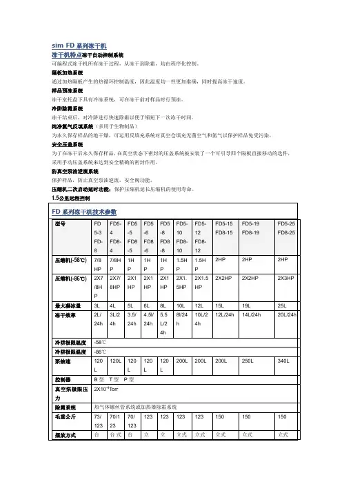
sim FD系列冻干机冻干机特点冻干自动控制系统可编程式冻干机所有冻干过程,从冻干到除霜,均由程序化控制。
隔板加热系统通过加热隔板产生的热循环控制温度,因此温度均一性更加准确,同时提高冻干速度。
样品预冻系统冻干室托盘下具有冷冻系统,可在冻干前对样品时行预冻。
冷阱除霜系统冻干结束后,对冷阱进行快速除霜以便于缩短下一次冻干时间。
纯净氮气反填系统(多用于生物制品)为永久保存样品的地干燥,可运用反填充系统对真空仓填充无菌空气和氮气以保护样品免受污染。
安全压盖系统为了在冻干后永久保存样品,在真空状态下密封的压盖系统被安装了一个可引导四个隔板直接移动的选件,采用手动压盖系统来达到安全精确的密封作用。
防真空泵油逆流系统保护样品,防止真空泵油逆流,安全阀功能。
压缩机二次启动延时功能:保护压缩机延长压缩机的使用寿命。
1.5公里远程控制FD系列冻干机技术参数型号FD5-3FD-8 FD5-4FD8-4FD5-5FD8-5FD5-6FD8-6FD5-8FD8-8FD5-10FD8-10FD5-12FD8-12FD5-15FD8-15FD5-19FD8-19FD5-25FD8-25压缩机(-58℃)7/8HP 7/8HP1HP1HP1HP1.5HP1.5HP2HP 2HP 2HP压缩机(-86℃)2X7/8HP 2X7/8HP2X1HP2X1HP2X1HP2X1.5HP2X1.5HP2X2HP 2X2HP 2X3HP最大凝冰量3L 4L 5L 6L 8L 10L 12L 15L 19L 25L冻干效率2L/24h 3L/24h3.5/24h4.5l/24h5.5L/24h8l/24h10L/24h12L/24h 14L/24h 20L/24h冷阱极限温度-58℃冷阱极限温度-86℃泵抽速120L 120L 120L120L120L200L 200L 200L 250L 340L控制器B型T型P型真空泵极限压力2X10⁻⁴Torr除霜系统热气体螺丝管系统或加热器除霜系统毛重公斤73/123 70/12370/123123 123 123 123 150 150 150摆放方式台台式台立立立式立式立式立式立式式/立式/立式式/立式式式电源要求220V , 50/60Hz 单相380V 380V 380V。

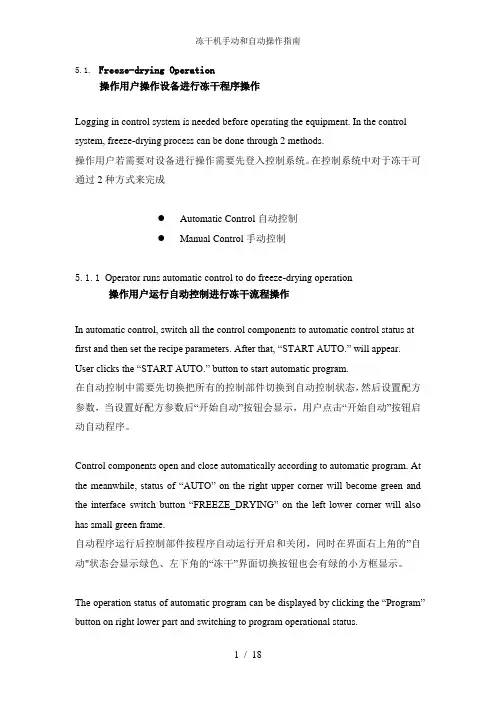
5.1.Freeze-drying Operation操作用户操作设备进行冻干程序操作Logging in control system is needed before operating the equipment. In the control system, freeze-drying process can be done through 2 methods.操作用户若需要对设备进行操作需要先登入控制系统。
在控制系统中对于冻干可通过2种方式来完成●Automatic Control自动控制●Manual Control手动控制5.1.1Operator runs automatic control to do freeze-drying operation操作用户运行自动控制进行冻干流程操作In automatic control, switch all the control components to automatic control status at first and then set the recipe parameters. After that, “START AUTO.” will appear. User clicks the “START AUTO.” button to start automatic program.在自动控制中需要先切换把所有的控制部件切换到自动控制状态,然后设置配方参数,当设置好配方参数后“开始自动”按钮会显示,用户点击“开始自动”按钮启动自动程序。
Control components open and close automatically according to automatic program. At the meanwhile, status of “AUTO” on the right upper corner will become green and the interface switch button “FR E EZE_DRYING” on the left lower corner will also has small green frame.自动程序运行后控制部件按程序自动运行开启和关闭,同时在界面右上角的”自动"状态会显示绿色、左下角的“冻干”界面切换按钮也会有绿的小方框显示。
冷冻干燥机使用说明
冷冻干燥机使用说明及注意事项
开机操作:
1.连接好电源,打开右侧黄色电源开关,此时“冷肼”显示窗开始显示冷肼的温度;
2.按一下“制冷机”开关,制冷机开始运转,冷肼温度开始降低,为使冷肼有充分的吸附
水分的能力,预冷时间应不少于30分钟;
3.按一下“真空计”开关,此时真空度显示为“999”;
4.预冷结束后,将已经准备好的待干燥物品置于干燥盘中,再将有机玻璃罩盖上;
5.按下快速充气阀(位于左前面板)上的不锈钢按片,听到咔嚓声后,将快速充气阀接嘴
拔出来,以自动密封;
6.按下“真空泵”开关,真空泵开始工作,真空度显示“999”,直到1000Pa一下,方可
显示实际真空度,冷冻干燥进程开始。
注:在真空泵开始工作时,用力下压有机玻璃罩片刻,有利于密封。
关机操作:
1.将快速充气阀接嘴插入快速充气阀座,同时关“真空泵”电源开关,使空气缓缓进入冷
肼,如需冲入惰性气体,则将惰性气体的减压导管连接“充气口”;
2.关“真空计”“制冷机”,如长期不用应拔掉电源线;
3.提起有机玻璃罩,将物品取出,保存,冷冻干燥结束;
4.冷肼中的冰化成水后,需将水从快速充气阀口排除,操作与充气相似;
5.清理冷肼中的水分和杂质,妥善保养设备。
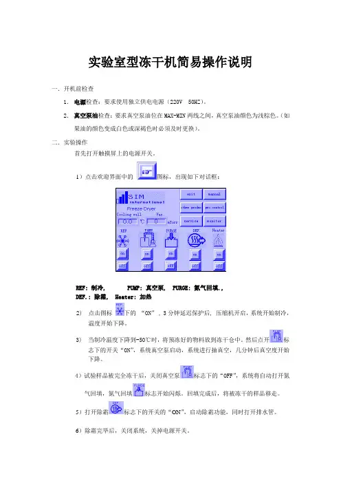
实验室型冻干机简易操作说明
一.开机前检查
1.电源检查:要求使用独立供电电源(220V 50HZ)。
2.真空泵油检查:要求真空泵油位在MAX-MIN两线之间,真空泵油颜色为浅棕色。
(如果油的颜色变成白色或深褐色时必须及时更换)。
二.实验操作
首先打开触摸屏上的电源开关。
1)点击欢迎界面中的图标,出现如下对话框:
REF: 制冷, PUMP: 真空泵, PURGE: 氮气回填.,
DEF.: 除霜, Heater: 加热
2) 点击图标下的“ON”, 3分钟延迟保护后, 压缩机开启,系统开始制冷,
温度开始下降。
3) 当制冷温度下降到-50℃时,将预冻好的物料放到冻干仓中。
然后点开标
志下的开关“ON”,系统真空泵启动,系统进行抽真空,几分钟后真空度开始
下降。
4)试验样品被完全冻干后,关闭真空泵标志下的“OFF”,系统将自动打开氮气回填,氮气回填标志开始闪烁。
回填完成后,将被冻干的样品移走。
5)打开除霜标志下的开关的“ON”,启动除霜功能,同时打开排水管。
6)除霜完毕后,关闭系统,关掉电源开关。
冻干机使用说明书一、产品介绍冻干机是一种用于冷冻和脱水食品和其他物品的设备。
它采用冷冻和真空技术,能够将食物或其他物品的水分迅速转化为固态,从而达到长时间保存和保鲜的目的。
本使用说明书将为您详细介绍冻干机的使用方法和注意事项。
二、使用方法1. 将冻干机放置在通风良好的平稳表面上,确保设备的稳定性。
2. 连接电源并打开开关,将设备预热至所需温度。
3. 准备待冻干的食物或其他物品,确保它们处于最佳状态。
4. 将食物或物品均匀地摆放在冻干机的托盘上,避免重叠。
5. 将托盘放入冻干机内,并确保托盘与设备接触良好。
6. 关闭设备的门,并打开真空泵开关,开始抽真空。
7. 根据不同物品的厚度和种类,设定适当的冻干时间和温度。
8. 稍作等待,直到设定的冻干时间结束,冻干机会自动停止工作。
9. 关闭真空泵开关,并打开设备门,取出冻干的物品。
10. 将冻干的物品储存在干燥、阴凉的地方,确保其长时间保鲜。
三、注意事项1. 在使用冻干机之前,务必先仔细阅读使用说明书并按照指示进行操作。
2. 使用冻干机时,请确保设备周围没有易燃物品,并保持通风良好。
3. 使用电源时,请确保电源电压与冻干机电源要求相符。
不要随意更换电源线,以免发生电气事故。
4. 当设备出现故障或异常时,请立即停止使用,并联系售后服务中心进行维修。
5. 在冻干的过程中,尽量避免频繁打开设备门,以免影响冻干效果。
6. 冻干机表面温度较低,请勿直接用手触摸,以免烫伤。
7. 清洁设备前,请先断开电源,并等待设备完全冷却。
8. 清洁设备时,请使用柔软的布进行擦拭,避免使用含有酸性或碱性成分的化学品。
9. 在清洁或维修设备时,请勿直接接触或擦拭设备内部的电器元件。
10. 若长时间不使用冻干机,请及时断开电源。
四、常见问题解答1. 为什么在冻干过程中设备会发出噪音?答:冻干机在工作过程中,会产生一定的噪音,这是正常现象,不会影响设备的使用和效果。
2. 冻干机的冻干时间和温度如何设置?答:冻干时间和温度的设置需根据不同的食物或物品种类来确定,具体的设置方式请参考食品或物品的冻干指导或咨询专业人士。
冷冻干燥机操作说明冷冻干燥机是一种重要的设备,广泛应用于食品、制药、生物科技等领域。
正确操作冷冻干燥机不仅可以保证工作效率和质量,还能提高设备的寿命。
本文将详细介绍冷冻干燥机的操作步骤及注意事项,以帮助用户正确使用该设备。
1. 设备准备在使用冷冻干燥机之前,首先需要确保设备处于良好的工作状态。
检查设备是否有损坏或漏水情况,并保证所需的冷却剂和真空泵等附件齐全。
如果发现设备有任何故障或缺陷,应及时联系维修人员进行维修或更换。
2. 准备样品在操作冷冻干燥机之前,需要准备好要干燥的样品。
确保样品干净并符合适当的规格和尺寸。
根据样品的特性,选择合适的冷冻温度和真空度进行设定。
3. 打开电源按下设备的电源开关,打开冷冻干燥机的电源。
待设备启动后,确保所有仪表指示均正常显示。
4. 设定工艺参数根据样品的要求,通过控制面板设定冷冻温度、真空度和干燥时间等工艺参数。
确保所有参数设定正确并合理。
5. 加载样品将准备好的样品放入设备的干燥室中。
注意不要超过设备的承载能力,并确保样品分布均匀,以充分利用设备的干燥效果。
6. 启动冷冻系统和真空系统按下冷冻系统和真空系统的启动按钮,使其开始工作。
在启动过程中,需要密切观察设备的运行情况,确保冷却剂和真空泵等系统正常工作。
如发现任何异常,应及时停止设备并检查故障原因。
7. 监控干燥过程在干燥过程中,应密切监控设备各个参数的变化,并根据需要进行调整。
特别注意干燥室内的温度和湿度,及时调整冷冻温度和真空度以确保干燥效果良好。
8. 停止设备当干燥时间达到设定值或者样品已经完全干燥时,关闭冷冻干燥机的冷冻和真空系统,并按下设备的停止按钮,使其停止工作。
9. 清洁和维护在停止设备后,及时清洁冷冻干燥机的内外部分,并保持设备的卫生。
检查设备是否有漏水或损坏的情况,并及时修理或更换。
以上就是冷冻干燥机的操作说明,希望用户能够按照以上步骤正确操作该设备,并注意安全。
在使用过程中,如遇到任何问题,请及时与设备制造商或专业维修人员联系。
冷干机使用说明书一、冷冻式干燥机工作原理冷冻式干燥机利用冷冻除湿原理,通过蒸发器强制压缩空气进行热交换,使其降温,从而将气态水和油凝结成液态,并夹带尘埃,通过自动排水器排出系统外,实现清洁的压缩空气。
改写:冷冻式干燥机通过冷冻除湿原理,强制压缩空气在蒸发器中进行热交换,从而将气态水和油凝结成液态,并通过自动排水器排出系统外,实现压缩空气的清洁。
二、冷冻式干燥机主要零部件图解改写:冷冻式干燥机的主要零部件图解。
三、设备安装注意事项1.冷冻式干燥机安装标准要求包括:基础水平坚固,排水系统高度和地沟设置要考虑,无需安装地脚螺栓。
2.冷冻式干燥机需安装在环境温度高于0℃低于38℃的地方,不宜置于温度高、通风不良或尘埃多的场所。
风冷式冷干机必须安装在室内,并具有通气设备以维持正常工作。
风冷型冷冻式干燥机置于空压房内时,需与空压机隔热。
警告:通风不良会导致热空气通过风冷冷凝器流反复,使室温不断升高,导致设备停止运转。
3.安装时应避免管道过长、弯曲角度过多、管径过小,以免产生压力降。
设备空气进出口口上方应加装旁路阀以便检修。
改写:设备安装时需注意基础水平的坚固,排水系统的高度和地沟设置,以及避免安装在温度高、通风不良或尘埃多的场所。
同时,管道长度、弯曲角度和管径也需注意,设备空气进出口口上方应加装旁路阀以便检修。
四、SLAD系列冷冻式干燥机操作方法改写:SLAD系列冷冻式干燥机的操作方法。
五、常规控制仪表板说明改写:常规控制仪表板的说明。
六、冷干机的启动过程改写:冷干机启动的过程。
七、冷干机的停机过程改写:冷干机停机的过程。
八、冷干机的保养要求设备保养要求包括:定期更换滤芯、清洗冷凝器和蒸发器、检查排水系统和电气接线、定期检查压缩机油位和油品、检查电机和风扇的运转情况。
改写:冷干机的保养要求包括定期更换滤芯、清洗冷凝器和蒸发器、检查排水系统和电气接线、检查压缩机油位和油品、检查电机和风扇的运转情况。
九、冷干机的典型故障分析和处理常见故障包括:压缩机无法启动、压缩机运转但无制冷效果、排水系统堵塞、制冷效果变差等。
冻干机操作手册一、设备介绍冻干机是一种用于冷冻干燥生物样品、药品、食品等物质的设备。
它通过将样品在低温下快速冷冻,然后将其置于真空环境中,使水分从样品中升华,从而达到干燥的目的。
冻干机操作手册是为了帮助用户正确、安全地使用设备,提高干燥效果和保护样品质量而编写的。
二、操作步骤1、准备阶段在开始操作冻干机之前,请确保您已经仔细阅读了本操作手册,并具备足够的技能和知识来操作该设备。
同时,请确保您已经了解了所干燥的样品特性,并知道如何处理可能的风险。
2、样品准备将需要干燥的样品进行适当处理,以避免在冻干过程中产生样品污染或损失。
根据样品的性质和大小,可以选择使用不同的容器或托盘来放置样品。
3、设备准备在操作冻干机之前,请检查设备的电源线是否连接良好,设备是否处于安全状态。
然后,打开设备的电源,启动设备,并等待设备达到所需的工作温度。
4、冻干过程将准备好的样品放入设备的冻干腔室中,然后开始进行冻干操作。
在冻干过程中,设备会不断监测温度和真空度等参数,并自动调整工作状态以保持稳定。
5、结束冻干当样品干燥完成后,设备会自动停止工作,并发出提示音。
此时,可以打开设备的门,取出已经干燥好的样品。
6、清理和维护在每次使用完冻干机后,请对设备进行清理和维护,以确保设备的良好状态和延长设备的使用寿命。
具体清理和维护事项可以参考设备的维护手册。
三、安全提示1、在操作冻干机时,请务必遵守本操作手册中的规定和指导,以确保您的安全和设备的正常运行。
2、请勿在冻干机的工作区域内放置任何与工作无关的物品,以保证设备的正常运行和防止火灾等意外事故的发生。
3、在使用设备前,请务必检查设备的电源线是否破损或松动,以避免触电或火灾等危险情况的发生。
4、在使用设备时,请勿打开设备的门或触摸设备的内部部件,以防止受伤或设备损坏。
5、在使用设备时,请勿离开设备,以防止设备出现故障或意外情况时无法及时处理。
在生态系统中,植物和微生物之间的关系复杂且多变。
新冷干机使用说明书(中英文)SLAD系列操作使用说明书目录一、冷冻式干燥机原理 (2)二、冷冻式干燥机零部件图解 (3)三、设备安装事项…………………………………………………………………4-6四、SLAD系列冷冻式干燥机操作方法…………………………………………6-7五、常规控制仪表板说明 (7)六、冷冻式干燥机的启动过程 (8)七、冷冻式干燥机的停机过程 (8)八、冷冻式干燥机的保养要求…………………………………………………9-10九、冷冻式干燥机的典型故障分析和处理……………………………………11-14冷冻式干燥机工艺流程冷冻式干燥机主要零部件图解设备安装注意事项一、冷冻式干燥机安装标准要求:无须安装地脚螺栓,但要求基础水平坚固,并要顾及排水系统的高度和设置排水地沟。
二、冷冻式干燥机避免安置于屋外直接日晒和雨淋或温度高、通风不良以及尘埃多的场所,需安装在环境温度高于0℃低于38℃的地方,风冷式冷冻式干燥机必须安置在室内,并具有良好的通气设备以维持冷冻式干燥机的正常工作。
安装在空压房内的风冷式冷冻式干燥机,要采取冷冻式干燥机与空压机的隔热措施。
将风冷冷冻式干燥机置于可使冷却空气便于通过冷凝器的地方,设备与周围环境或机器之间的距离应保持在1米以上的空间便于保养和维修。
三、安装时应尽量避免管道太长,弯曲角度太多,管径太小,以免产生压力降,设备空气进出口口上方请加装旁路阀以利检修。
四、安装冷冻式干燥机电源时电器接线可能在运输过程中由于震动而松动,请用工具拧紧,并注意以下几点:警告通风不良将导致冷凝后的热空气流反复通过风冷冷凝器而使室温不断升高。
这将导致制冷压缩机排气压力过高使冷媒高压开关保护或使电机内部过载保护,最终使设备停止运转。
1、额定电压在±5%范围以内。
2、电源进线的线径须视电流大小及线路长短而定。
3、SLAD-0.5NF∽8.5NF电源须专用。
警告连接冷冻式干燥机的电线必须符合国际(IEC)和地方上的法规和标准,并检查设备铭牌上标明的电压,电线的连接必须由专业电工人员操作。