钻铣床主轴箱数控化设计
- 格式:pdf
- 大小:180.60 KB
- 文档页数:3
本科毕业设计(论文)题目:JCS-013型自动换刀数控卧室镗铣床主轴箱设计系别:机电信息系专业:机械设计制造及其自动化班级:学生:学号:指导教师:2013年05月摘要机械行业是运用数控机床最多的,很多企业为了提高自己的生产效率,常常会对机床内部结构进行多方面的改造。
社会主义市场经济的发展为我国工业生产创造了条件,在现代一体化生产模式中运用了很多先进的设备。
对于数控机床而言,主轴箱是其最为核心的组织结构,整个主轴箱影响着数控机床的变速情况。
大部分制造企业在实行技术改造时把重点放在了主轴箱变速器上,这是调整机床运行速度的重点。
在设计过程中必须要对主轴箱的每个部件加以控制,这样才能确保数控机床主轴变速性能的良好。
本文对主轴箱变速操纵机构的工作原理进行结构设计和计算分析,利用两个液压油缸,经拨叉带动双联滑移齿轮移动到需要的多个位置。
关键字:数控机床;主轴箱;结构;设计AbstractMachinery industry is the use of CNC machine tools the most, a lot of enterprises to improve their production efficiency, often transform many aspects of the internal structure of machine tool. The society pays attention to the development of the market economy to create the conditions for the industrial production of our country, a lot of advanced equipment for use in the integration of modern production mode. For NC machine tool, the spindle box is the most core structure, the spindle box of CNC machine tool gear case. Most of the manufacturing enterprises in the implementation of technical transformation to focus on the main spindle box transmission, which is the key to adjust the machine running speed. In the design process must each component of the headstock to control, so as to ensure the good performance of NC machine tool spindle speed.In this pear, the working principle of the headstock gear control mechanism on the analysis of the structure design and calculation, using two hydraulic oil cylinders, the shifting fork drives a sliding duplex gear moving to a plurality of positions need.Key Words:CNC machine; machine head; structure; design目录1绪论 (1)1.1数控镗铣床的结构组成 (1)1.2我国卧式镗铣床的发展 (2)1.2.1我国卧式镗铣床的发展历史 (2)1.2.2我国卧式镗铣床的发展趋势 (2)2数控卧式镗铣床变速操纵机构设计 (4)2.1主轴箱变速操纵机构工作原理 (4)2.2主轴箱变速操纵机构中传动轴的安装 (5)2.3齿轮在轴上的布置和排列 (5)2.4 相啮合齿轮的宽度 (6)3主传动系统的设计计算 (7)3.1电动的选取 (7)3.1.1选择电动机的类型 (7)3.1.2转速及功率的确定 (7)3.1.3联轴器的选择 (7)3.1.4选定各齿轮齿数 (7)3.1.5转速的计算 (7)3.1.6各轴功率及转矩的计算 (8)3.2齿轮的设计 (8)3.2.1确定齿轮齿数的原则和要求 (8)3.2.2齿轮传动设计参数的选择 (8)3.2.3齿轮的结构设计计算 (9)3.3轴的设计 (12)3.3.1轴的结构设计 (12)3.3.2轴上作用力的计算 (14)3.3.3轴的结构设计 (14)3.3.4键的选取 (16)3.3.5 轴的受力分析 (16)3.3.6校核轴的强度 (17)3.3.7校核键连接的强度 (18)3.3.8校核轴承寿命 (18)4箱体的设计 (20)5传动系统的润滑 (21)总结 (22)参考文献 (23)致谢 (24)毕业设计(论文)知识产权声明........................错误!未定义书签。
摘要从研究数控铣床入手,借鉴国内外先进经验,设计一台用于ZK9350数控轴承保持架加工的专用数控钻铣床,满足了生产和设计的要求。
整个数控钻铣床主要包括横纵向进给机构,立柱、横梁、底座、工作台等主要组部件。
本次设计任务从整个数控钻铣床着眼,重点设计床身及滑台结构。
从专用数控钻铣床的结构原理,设计特点,论述了采用矩形-燕尾形滑动导轨的优点。
详细介绍了数控钻铣床的床身结构设计,并进行了分析。
论述了采用伺服电机和滚珠丝杠螺母副的优点。
详细介绍了数控龙门钻床的结构设计及校核,并进行了分析。
另外汇总了有关技术参数。
其中着重介绍了滑动导轨的原理及选用原则,中心在于立式钻铣床的布局形式,关键在于床身的截面选择、箱体的壁厚选择及床身的强度,系统地对导轨生产、保养等环节进行了介绍,包括种类选择、参数选择、精度选择、润滑方式选择等。
关键词钻铣床滚珠丝杠伺服电机滑动导轨AbstractBegins from the research CNC milling machine, to profit from the domestic and foreign advanced experiences, design one to use in the dedicated numerical control CNC drilling and milling machine for ZK9350 CNC bearing cage processing, has satisfied the production and the design request. The entire milling machine including parts of the horizontal and verticalfeed mechanism, columns, beams, base, table and other major groups. The design tasks keeps the entire CNC drilling and milling machine in mind, focus on the design of the bed and slide structure.Begins from the dedicated numerical control CNC drilling and milling machine's principle of the structure, and discusses the advantages of a rectangle-dovetail shaped sliding C drilling and milling machine bed structural design and analysis. discusses the use of servo motor and ball screw pair of the C gantry drilling machine described in detail the structure of the design and verification, and analyzed Addition, a summary of the technical parameters.In which introduced emphatically the principle of the sliding rail and selection principles, the center is the layout form of vertical drilling milling machine, the key is the bed cross-section selection. Introduce rail production, maintenance and other aspects of the presentation, Including species selection, parameter selection, precision selection, lubrication mode selection and so on.Keywords : drilling and milling machine, bearing guide screw nut Step-by-steps the electrical machineryBall, sliding rail目录摘要 (I)Abstract ................................................................................................................................................. I I 1.综述 (1)1.1 国外数控机床业的发展状况及趋势 (1)1.2国内数控机床业的发展状况及存在问题 (4)1.2.1 国内数控机床业的发展状况 (4)1.2.2 国内数控机床业存在问题 (5)1.3 数控机床的工作原理及组成 (7)1.3.1 数控机床的工作原理 (7)1.3.2 数控机床的组成 (7)1.4 专用数控钻铣床的应用及意义 (7)1.4.1 专用机床 (7)1.4.2 钻铣床的应用 (9)2 专用数控钻铣床的床身及滑台 (11)2.1 专用数控钻铣床的床身 (11)2.1.1 专用数控钻铣床的床身的简介 (11)2.1.2 专用数控钻铣床的床身的应用及要求 (12)2.1.3 我国当前数控机床床身现状 (13)2.2 专用数控钻铣床的滑台 (13)2.2.1 专用数控钻铣床的滑台及作用 (13)2.2.2 导轨的简介、设计要求及步骤 (14)2.2.3 直线滑动导轨 (16)2.2.4 滚动导轨 (18)3 专用数控钻铣床的参数 (21)3.1 床身参数 (22)3.1.1机架的截面形状 (22)3.1.2 床身壁厚的选择 (23)3.1.3 合理布置加强肋 (24)3.1.4 支承件的设计 (25)3.1.5 机架的联接结构设计 (28)3.2 导轨的参数 (29)3.2.1 导轨面的尺寸 (29)3.2.2 导轨间隙调整装置 (30)3.2.3 导轨材料的热处理 (30)3.2.4 滑动导轨磨损的基本形式 (31)3.2.5 导轨的润滑和防护 (31)3.2.6提高导轨的耐磨性措施 (32)3.3 滚珠丝杠副的设计 (33)3.3.1 滚珠丝杠介绍 (34)3.3.2 滚珠丝杠的结构 (34)3.3.3 滚珠丝杠原理 (35)3.3.4 滚珠丝杠的特点 (36)3.3.5 滚珠丝杠副结构类型 (36)3.3.6 滚珠丝杠副性能 (36)3.3.7 滚珠丝杠副在高速驱动时主要存在的问题 (37)3.3.8 滚珠丝杠的选用 (37)3.3.9 确定丝杠型号 (39)3.3.10 丝杠的校核计算 (39)3.4 伺服电机的选择 (40)4 主传动系统的设计 (41)4.1主传动系统的设计 (41)4.1.1电主轴的概述 (41)4.1.2电主轴的结构 (42)4.1.3高速电主轴结构特点 (43)4.1.4电主轴工作原理 (44)4.1.5电主轴所融合的技术 (44)4.1.6电主轴的选型 (45)4.1.7主轴刚度和刚度损失的计算: (47)5 总结 (49)致谢 (50)参考文献 (51)1.综述1.1 国外数控机床业的发展状况及趋势数控机床涌现至今已有60年,随科技特别是随着微电子、计算机技术的前进而不断发展。
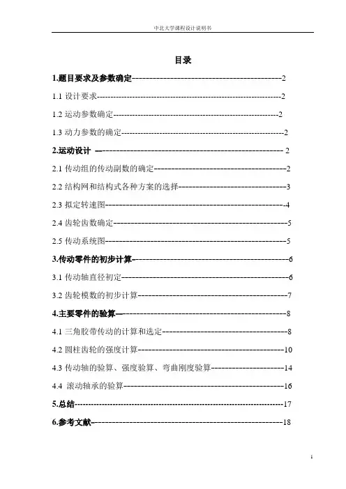
目录1.题目要求及参数确定-------------------------------------------2 1.1设计要求--------------------------------------------------------------------2 1.2运动参数确定-------------------------------------------------------------21.3动力参数的确定------------------------------------------------------------22.运动设计------------------------------------------------------ 2 2.1传动组的传动副数的确定--------------------------------------2 2.2结构网和结构式各种方案的选择-------------------------------3 2.3拟定转速图----------------------------------------------------4 2.4齿轮齿数确定--------------------------------------------------52.5传动系统图----------------------------------------------------53.传动零件的初步计算---------------------------------------------6 3.1传动轴直径初定------------------------------------------------63.2齿轮模数的初步计算-------------------------------------------74.主要零件的验算-------------------------------------------------8 4.1三角胶带传动的计算和选定------------------------------------8 4.2圆柱齿轮的强度计算------------------------------------------10 4.3传动轴的验算、强度验算、弯曲刚度验算---------------------144.4 滚动轴承的验算----------------------------------------------165.总结-----------------------------------------------------------------------------176.参考文献-------------------------------------------------------181. 题目要求及参数确定1.1设计要求1)机床的类型、用途及主要参数铣床,工作时间:二班制,电动机功率: 1.5N KW =,主轴最高、最低转速如下: max 1250n rpm =,min 100n rpm =变速级数:z=12。
XK6130数控卧式铣床总体及主轴箱设计机械设计制造及其自动化09010802 李积才指导老师胡世军副教授摘要本次设计的是数控卧式铣床,它是一种科技含量高的机电一体化设备。
目前,数控铣床在我国发展较快,它的应用是机器制造过程发生了巨大的变化。
本说明书是本次毕业设计的概要说明。
重点叙述了数控铣床的基本概况,国内发展史,现状和发展趋势,数控铣床的总体方案拟定,主传动系统,主轴箱的设计原理,具体结构,计算方法,数控系统的选型和其他内容。
关键词:数控卧式铣床主轴主轴箱设计AbstractThis design is the numerical control sign type miller. It is a kind of machine of the high technology electricity the integral whole turn on equipments, currently. The machine manufacturing process take place huge variety.This instruction booket is my this graduation progect outline explained that with emphasis narrated the numerical control miller basic survey, domestic and foreign histories, present situation and trend of development. The numerical over concept draws ups, master driver system, head stock, principle of design, concrete structure computational method, numerical control system shaping and other and so on contents.Keywords: The numerical control sign type miller principal axia head stock design本人有这套毕业设计的全部内容包括尺寸联系图、传动系统图、电气原理图、装配图、零件图、三维图、说明书等,都是电子版的,要的QQ我.QQ:2857104一、机床的主要设计参数1.主轴转速:30—1500转/分2.工作台尺寸(长╳宽):1250mm╳360mm3.工作台最大行程:纵向 800mm 横向 300mm 垂直 400mm4.快速移动速度: 10m/min5.工作台定位精度 x、y、z、±0.03mm;工作台重复定位精度x、y、z、±0.02mm;6.纵向、横向及垂直进给为微机控制,采用步进电机或直流伺服电机驱动,滚珠丝杠传动,脉冲当量0.010mm/脉冲。
目录目录 (1)1. 机床参数确定: (1)2. 运动设计 (1)2.1 传动组、传动副的确定: (1)2.2 结构式、结构网的选择: (2)2.3 拟定转速图: (2)2.4 齿轮齿数确定 (4)2.5传动系统图如图四所示: (5)2.6轴、齿轮的计算转速: (5)2.7展开图简图 (7)3. 传动零件的初步计算: (7)3.1传动轴直径初定 (7)3.2 主轴轴颈直径的确定 (8)3.3 齿轮模数的初步计算 (8)4. 主要零件的验算 (9)4.1 V带传动的计算和选定 (9)4.2 圆柱齿轮的强度计算: (10)4.3主轴的验算 (12)4.4 滚动轴承的验算 (13)参考文献 (15)1. 机床参数确定:运动参数: 回转主运动的机床,主运动的参数是主轴转速。
其数列的公比φ应选取标准的公比值,取公比φ=1.26。
主轴转速级数:12126.1lg 5.12lg 1lg lg =+=+=ϕn R z 式中Rn 为主轴变速范围:5.121001250min max ===n n R n 。
机床传动系统的变速组大多采用双联齿轮或三联齿轮,因此转速级数宜为2、3因子的乘积,即n m Z 23⋅=为宜,其中m 、n 为正整数。
动力参数:由任务书设定电动机功率:N=3KW 。
查表应选用Y 系列三相异步电动机Y100L2-4,转速1420 r/min ,效率82.5%。
功率因素cos φ=0.81,额定转矩2.2KNm 。
2. 运动设计2.1 传动组、传动副的确定:实现12级主轴转速变化的传动系统可以写成多种传动副组合: 1)12=3×4 2)12=4×3 3)12=3×2×2 4)12=2×3×2 5)12=2×2×3方案1)、2)可以省一根传动轴,但是其中一个传动组内有四个传动副,果增大了该轴的轴向尺寸这种方案不宜采用。
目录绪论 (1)第1章主传动系统设计概述 (3)第2章数控铣床主传动系统的配置方式 (4)第3章主轴电动机的选取 (5)第4章同步带传动设计与计算 (6)4.1、同步材料选择 (6)4.2、同步带参数的计算 (6)4.2.1、模数的选取 (6)4.2.2、小带轮齿数 (6)4.2.3、同步带节距 (6)4.2.4、节圆直径 (7)4.2.5、大带轮齿数 (7)4.2.6、大带轮直径 (7)4.2.7、带的速度 (7)4.2.8、定中心距 (7)4.2.9、带的节线长度 (7)4.2.10、计算中心距 (7)4.2.11、带轮与带的啮合齿数 (8)4.2.12、带宽 (8)4.2.13、作用在轴上的力 (8)4.2.14、小带轮的最小包角 (8)4.2.15、带轮宽度 (8)第5章主轴组件的设计 (9)5.1、主轴组件的设计要求 (9)5.1.1、回转精度 (9)5.1.2、主轴刚度 (9)5.1.3、主轴的抗振性 (10)5.1.4、主轴温升 (10)5.1.5、主轴耐磨性 (10)5.1.6、提高主轴组件抗振性的措施 (10)5.2、减少主轴组件热变形的措施 (10)5.3、主轴材料的选择及尺寸、参数的计算 (11)5.4、主轴转动装置箱体的作用 (13)5.5、主轴箱体的截面形状和壁厚的计算 (15)第6章主轴轴承的选择 (15)6.1、轴承的选择和轴承的精度 (15)6.2、轴承预紧力的要求 (15)6.3、主轴轴承的润滑与密封 (16)6.4、选取轴承求 (16)6.5、轴承寿命校核 (18)6.6、轴承座孔的设计要求 (19)第7章联接键的选择碟形弹簧的选择与计算 (20)7.1、碟形弹簧的特点 (20)7.2、碟形弹簧材料及热处理厚度和脱碳 (21)7.3、碟形弹簧的强压处理 (21)7.4、表面强化处理和防腐处理 (21)第8章螺钉联接的设计 (23)8.1、根据设计要求计算 (23)8.2、螺钉的强度计算与校核 (23)第9章液压缸的设计 (24)9.1.液压压缸安装应注意的问题 (24)9.2.压缸各部分的结构及主要尺寸的确定 (24)9.3.强度校核 (25)第10章润滑与密封件设计 (26)10.1、封件的作用及其意义 (26)10.2、密封的分类及密封件的材料要求 (26)10.3、防尘圈的设计要求 (27)结论 (28)致谢……………………………………………………………………………….................. .29参考文献………………………………………………………………………….................. ..30绪论数控技术,简称数控(Numerical Control)。

摘要目前中国企业中机床设备老化,不能满足新技术、新工艺的生产要求。
本文重点介绍Z5140A型台式钻床的数控改装方案和单片机系统设计,将传统的机械与现有的数控技术相结合,使其具有自动进给功能,为企业进行设备的数控化改造提供了一种有效可行的途径。
现有的Z5140A型台式钻床经改造后提高了加工精度,扩大了机床的使用范围,并提高了生产率。
本论文说明了普通钻床的数控化改造的设计过程,较详尽地介绍了Z5140A机械传动部分的设计及数控系统部分的设计。
通过该改造计划,改造后的Z5140A型钻床具备数控机床的精度要求,自动化柔性生产的能力。
机床整体能力达到预期的要求。
Z5140A数控钻床主要用于加工各种孔及平面和曲面的铣削。
它集中了立式钻床和铣床的功能。
数控钻床需要很少人工操作,也没有机械操作元件如手柄、摇把等。
该钻床如同其他CNC钻床,全部工作循环是在微机数控系统控制下实现的。
车削对象改变后,只需改变相应的软件就可适应新的需要。
由于利用的床身、立柱等基础件都是重而坚固的铸造构件,而不是那种焊接构件,改造后的机床性能高、质量好,可以作为新设备继续使用多年。
但是受到原来机械结构的限制,不宜做突破性的改造。
关键词:数控机床;滚珠丝杠;数控系统AbstractAt present,Machine tools made in China is aging and can not meet the requirements of new technologies and new processes of production. This paper focuses on the NC Z5140A-type drill press conversion programs and MCU system design. Combining the traditional machines with the CNC technology, it can realize automatically feed function and provides a feasible and effective way for the enterprise of equipment's transformation with NC.Existing Z5140-type drill press improves the machining accuracy, expands the scope of machine use and increases the productivity after transformation. This paper describes the design process of the transformation of the general drilling with NC, introduces the design of the Z5140A mechanical transmission part and numerical control system part in detail.After the transformation plan, Z5140A-type drill transformed has the accuracy requirement of CNC machine tools and the automatic flexible production capacity. Machine tools achieve the desired overall capacity requirements. Z5140A CNC drilling machine is mainly used for processing a variety of holes and planar and surface milling. It contains the vertical drilling and milling function. CNC drilling and milling machinerequires very little manual operation and no operation of machinery components such as handles, crank and so on. As with other CNC drilling of the drilling machine, all of the cyclic work is completed under the control of the computer numerical control system. As turning object changes, just change the corresponding software to adapt to new needs. Because lathebed, column and other basic items are heavy and casting equipments but not the welded components, machine tools transformed has higher performance and better quality, which can be used as a new equipment for years. However, limited by the mechanical structure of the original, it can not be transformed revolutionarily.Key Word:Numerical Control Machine Tools ; Ball Screw; CNC System目录摘要 ........................................ - 1 -Abstract ...................................... - 2 -1绪论......................................... - 6 -1.1 立式钻床的概述............................................................................................ - 6 -1.2 数控立式钻床的发展.................................................................................... - 6 -1.3 立式钻床数控化改造的市场 ....................................................................... - 8 -1.3.1 机床数控化改造的市场...................................................................... - 8 -1.3.2 立式钻床简介...................................................................................... - 9 -1.4床数控化改造的内容及优缺点 .................................................................. - 10 -1.4.1数控化改造的内容............................................................................. - 10 -1.4.2 立式钻床数控化改造的优缺点........................................................ - 11 -2主传动系统的设计............................ - 12 -2.1 立式钻床数控化改造设计任务 ................................................................. - 12 -2.2 总体方案的确定.......................................................................................... - 13 -2.2.1 Z向步进电机与进给滚珠丝杠的联结 ............................................. - 13 -2.2.2 传动形式的选择................................................................................ - 15 -2.2.3 滚珠丝杠副的参数............................................................................ - 16 -2.2.4 滚珠丝杠副的组成及特点................................................................ - 17 -2.2.5 滚珠丝杠副的典型结构类型............................................................ - 17 -2.2.6 滚珠丝杠的支撑形式选择................................................................ - 19 -2.3 Z向进给滚珠丝杠副的计算与校核 ................................................... - 22 -2.3.1主轴钻削力计算................................................................................. - 22 -2.3.2滚珠丝杠副的选择计算..................................................................... - 23 -2.3.3选择步进电动机................................................................................. - 26 -2.4 电主轴选用、冷却与润滑 ......................................................................... - 30 -2.4.1 电主轴的概述.................................................................................... - 30 -2.4.2 电主轴的冷却与润滑........................................................................ - 33 -2.4.3 电主轴的选用.................................................................................... - 35 -3数控系统电路设计............................ - 37 -3.1绘制系统电气控制的结构框图 .................................................................. - 37 -3.1.1 机床硬件电路有以下几部分组成.................................................... - 38 -3.2 MCS-51单片机简介 ................................................................................... - 38 -3.2.1 8031单片机的基本特性.................................................................... - 38 -3.2.2 8031芯片引脚及其功能介绍......................................................... - 40 -3.3存储器扩展电路设计................................................................................... - 42 -3.3.1 程序存储器的扩展............................................................................ - 42 -3.3.2 数据存储器的扩展............................................................................ - 44 -3.3.3 译码电路设计.................................................................................... - 45 -3.4 I/O接口扩展电路设计 ............................................................................ - 45 -3.4.1 8155通用可编程接口芯片................................................................ - 45 -3.4.2 8255可编程接器芯片........................................................................ - 47 -3.4.3 8255的结构........................................................................................ - 48 -3.5 其它辅助电路设计...................................................................................... - 49 -3.5.1 8031的时钟电路................................................................................ - 49 -3.5.2 越界报警和急停处理电路................................................................ - 49 -3.5.3 复位电路............................................................................................ - 49 -3.5.4 掉电保护电路.................................................................................... - 50 -3.5.5 键盘显示接口电路............................................................................ - 50 -4结论........................................ - 51 -致谢 ............................. 错误!未定义书签。
实践教学环节课程名称工艺装备设计课程编码佳木斯大學机械设计制造及其自动化专业(卓越工程师)设计说明书(工艺装备设计)题目:数控机床主轴箱箱体钻床夹具设计学院:机械工程学院专业:机械设计制造及其自动化姓名:指导教师:完成日期:2014年7月10日佳木斯大学机械工程学院2014年7 月目录第1章绪论 (1)1.1 工艺装备设计背景 (1)1.2 工艺装备发展史 (1)1.3 本章小节 (3)第2章机械加工工艺规程设计 (4)2.1 零件的分析 (4)2.1.1 零件的作用 (4)2.1.2 零件的工艺分析 (4)2.2 确定生产类型 (4)2.3 确定毛坯 (5)2.3.1 确定毛坯种类 (5)2.3.2 确定毛坯加工余量及形状 (5)2.4 工艺过程设计 (5)2.4.1 选择定位基准 (5)2.4.2 选择加工方法 (6)2.4.3 制定工艺路线及选用设备 (7)2.4.4 确定切削余量 (10)2.5 本章小结 (11)第3章夹具设计 (12)3.1 确定定位方案与定位元件 (12)3.2 确定夹紧方案与夹紧机构 (12)3.3 确定导向方案 (12)3.4 确定夹具体方案 (13)3.5 本章小结 (13)结论 (14)致谢 (15)参考文献 (16)附录一 (17)附录二 (18)第1章绪论1.1 工艺装备设计背景工具是人类文明进步的标志。
自20世纪末期以来,现代制造技术与机械制造工艺自动化都有了长足的发展。
但工具(含夹具、刀具、量具与辅具等)在不断的革新中,其功能仍然十分显著。
机床夹具对零件加工的质量、生产率和产品成本都有着直接的影响。
因此,无论在传统制造还是现代制造系统中,夹具都是重要的工艺装备。
随着科学技术的发展,各种新材料、新工艺和新技术不断涌现,机械制造工艺正向着高质量、高生产率和低成本方向发展。
各种新工艺的出现,已突破传统的依靠机械能、切削力进行切削加工的范畴,可以加工各种难加工材料、复杂的型面和某些具有特殊要求的零件。
AbstractOn April 19 unfolds from the seventh session of Chinese international engine bed learned that, develops unceasingly along with the science and technology, the numerical control engine bed development more and more is also quick, the numerical control engine bed also is facing the high performance, the high accuracy, the high velocity, the high flexibility and the modular direction develops. International manufacture technology exposition conducts which in the American Chicago, discovered the compound processing engine bed has become an important direction which the engine bed develops. Because the compound processing engine bed prominently manifested the work piece to complete in an attire card majority of or processes the working procedure completely, thus achieved reduced the engine bed and the jig, the exemption working procedure transporting and the storage, increased the work piece processing precision, reduced the processing cycle and saves the work area the goal. This article simply briefed the numerical control engine bed development tendency, as well as future aggregate machine-tool development key and aggregate machine-tool characteristic.In view of is processed the components to do the aggregate machine-tool system design, is processed by the detail drawing plan the components working procedure chart, the engine bedrelation dimensional drawing, the processing schematic drawing, as well as plan process heavy main point and limelight. By in the components hole position and the power determination headstock between various axes gear transmission relations, draw up the headstock assembly drawing by each kind of parameter. Finally designs the hardware circuit diagram to control the cutting tool the movement.Keyword: combination machine, main axle box, numerical control目录摘要- 1 -Abstract- 2 -目录- 3 -第一章数控组合机床的发展趋势及特点- 4 -1 .1 数控组合机床的发展趋势及特点- 4 -1.2 组合机床品种的发展重点以及特点- 5 -1.3 本论文工作的内容与安排- 5 -1.3.1. 主要技术参数:- 5 -1.3.2.设计任务- 6 -第二章组合机床工艺方案的制定- 6 -2.1 工艺基面的分析- 6 -2.1.1 已给定工艺基准及夹压部位- 6 -2.1.2 选择工艺基面的原则及注意问题- 6 -2.2 加工工艺的分析- 7 -第三章组合机床的总体设计- 7 -3.1 被加工零件的工序图- 7 -3.2 加工示意图- 8 -3.2.1 刀具的选择- 8 -3.2.2切削用量的选择- 8 -3.2.3 接杆的选择- 9 -3.2.4 导向结构的选择- 10 -3.2.5动力头工作循环及其行程的确定- 11 -3.3 机床联系尺寸图的绘制- 12 -3.3.1动力部件的选择- 12 -3.3.2 绘制机床联系尺寸图应考虑的主要问题- 16 -3.3.3 组合机床床身设计- 17 -3.4 组合机床主轴箱设计- 21 -3.4.1 概述- 21 -3.4.2 主轴箱的设计方法- 23 -第四章硬件电路图设计- 24 -4.1 微机数控系统的设计内容- 24 -4.2 MCS-51系列单片机及其扩展- 26 -4.2.1 MCS-51单片机的选择及简介- 26 -4.2.2 单片机的系统扩展- 26 -4.2.3 存储器扩展- 28 -4.2.4I/O口的扩展- 29 -设计总结- 31 -参考文献:- 31 -致谢- 31 -第一章数控组合机床的发展趋势及特点1 .1数控组合机床的发展趋势及特点随着科学技术不断发展,数控机床的发展也越来越快,数控机床也正朝着高性能、高精度、高速度、高柔性化和模块化方向发展。
课程设计(说明书)题目铣床工作台宽度为320 mm的普通铣床的主轴箱部件设计专业学生姓名班级学号指导教师二〇年月日摘要铣床工作台宽度为320 mm的普通铣床的主轴箱部件设计是机床设计中非常重要的组成部分,本次设计主要由机床的级数入手,于结构式、结构网拟定,再到齿轮和轴的设计,再选择各种主轴箱配合件,对轴和齿轮及配合件进行校核,将主轴箱方案“结构化”,设计主轴变速箱装配图及零件图,侧重进行传动轴组件、主轴组件、变速机构、箱体、润滑与密封、传动轴及滑移齿轮零件的设计,完成设计任务。
本次突出了结构设计的要求,在保证机床的基本要求下,根据机床设计的原则,拟定机构式和结构网,对机床的机构进行精简,力求降低生产成本;主轴和齿轮设计在满足强度需要的同时,材料的选择也是采用折中的原则,没有选择过高强度的材料从而造成浪费。
关键词:铣床、主轴箱系统、结构式、电动机。
铣床主轴箱系统设计全套图纸加153893706目录目录 (5)第1章绪论 (7)第2章铣床参数设计 (9)2.1铣床主参数和基本参数 (9)2.2 确定最大转速 (9)第3章运动设计 (10)3.1 主电机功率——动力参数的确定 (10)3.2确定结构式 (10)3.3 确定结构网 (11)3.4 绘制转速图和传动系统图 (11)3.5 确定各变速组此论传动副齿数 (12)3.6 核算主轴转速误差 (14)第4章动力计算 (15)4.1 带传动设计 (15)3.1计算设计功率Pd (15)3.2选择带型 (16)3.3确定带轮的基准直径并验证带速 (16)3.4确定中心距离、带的基准长度并验算小轮包角 (17)3.5确定带的根数z (18)3.6确定带轮的结构和尺寸 (18)3.7确定带的张紧装置 (18)3.8计算压轴力 (18)4.9 计算转速的计算 (19)4.10 齿轮模数计算及验算 (19)4.11 传动轴最小轴径的初定 (24)4.12 零件验算 (25)4.12.1 主轴刚度 (25)4.12.2 传动轴刚度 (30)4.12.3 齿轮疲劳强度 (33)4.13 轴承的选择 (35)4.14 键的规格 (35)4.15变速操纵机构的选择 (36)第5章主轴箱结构设计及说明 (36)5.1 结构设计的内容、技术要求和方案 (36)5.2 展开图及其布置 (36)第6章设计部分的调节、润滑、维护保养、技术要求及其它 (37)参考文献 (40)致谢 (41)第1章绪论机床的主轴箱系统的布局可分成集中传动和分离传动两种类型。
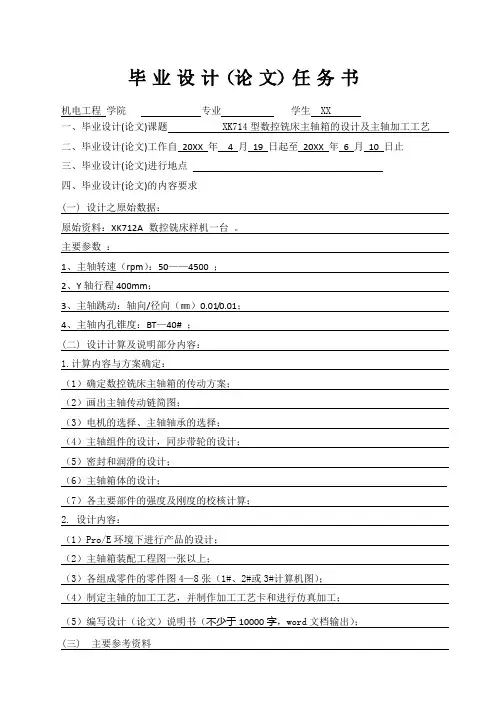
毕业设计(论文)任务书机电工程学院专业学生 XX一、毕业设计(论文)课题 XK714型数控铣床主轴箱的设计及主轴加工工艺二、毕业设计(论文)工作自20XX 年 4 月19 日起至20XX 年 6 月10 日止三、毕业设计(论文)进行地点四、毕业设计(论文)的内容要求(一) 设计之原始数据:原始资料:XK712A 数控铣床样机一台。
主要参数:1、主轴转速(rpm):50——4500 ;2、Y轴行程400mm;3、主轴跳动:轴向/径向(㎜)0.01/0.01;4、主轴内孔锥度:BT—40# ;(二) 设计计算及说明部分内容:1.计算内容与方案确定:(1)确定数控铣床主轴箱的传动方案;(2)画出主轴传动链简图;(3)电机的选择、主轴轴承的选择;(4)主轴组件的设计,同步带轮的设计;(5)密封和润滑的设计;(6)主轴箱体的设计;(7)各主要部件的强度及刚度的校核计算;2. 设计内容:(1)Pro/E环境下进行产品的设计;(2)主轴箱装配工程图一张以上;(3)各组成零件的零件图4—8张(1#、2#或3#计算机图);(4)制定主轴的加工工艺,并制作加工工艺卡和进行仿真加工;(5)编写设计(论文)说明书(不少于10000字,word文档输出);(三) 主要参考资料1、《机床设计手册》,机械工业出版社2、《机械师设计手册》,机械工业出版社3、《机械零件设计手册》,冶金工业出版社4、《工程力学》5、《金属切削机床》上海科学技术出版社6、《材料力学》,高等教育出版社。
7、《互换性与技术测量》中国计量出版社8、《金属切削机床概论》机械工业出版社9、《机械原理》(四)附属专题1、专题外文翻译检索与阅读与设计题目相关的外文资料,并书面翻译2~3篇(2000~3000字(附原文))外文资料。
指导教师接受设计论文任务开始执行日期20XX年4月19 日学生签名摘要高速加工是近年来发展起来的先进制造技术,电主轴是实现机床高速化的核心部件。
数控铣床的主轴箱结构设计摘要:本文主要有如下几个方面的内容1)主传动系统设计,其中包括主传动电机的选择及其型号的确定。
2)数控铣床主传动系统的配置方式,其中要考虑传动性能的最优化选择,如:传动准确,无滑动;传动效率高且传动平稳可靠,噪音小等。
4)同步带传动设计与计算,其中包括同步材料的选择和同步参数的计算。
5)主轴组件的设计。
6)主轴轴承的选择,其中包括轴承的精度,预紧力几轴承的润滑与密封等问题。
7)联接键的选择和碟形弹簧的选择与计算,这里要考虑弹簧的热处理问题。
8)螺钉联接的设计。
9)液压缸的设计。
10)润滑与密封件设计。
关键词:机械设计;数控三坐标铣床;主轴Main spindle box structure design of numerical control milling machineStudent: he yiTutor: chenzhiliang(Oriental Science &Technology College of Hunan Agricultural University, Changsha 410128)Abstract: This thesis mainly includes the following content: 1) main drive system design and it contained the content of selection main drive motor and its model. 2) configuration of numerical control milling machine main drive system and it shall consider optimization selection of drive performance, such as accurate drive, nonslip; high drive efficiency with stability, reliability and low noise etc. 3) design and calculation of synchronous belt drive including selection of synchronous material and calculation of synchronous parametric. 4) design of spindle parts. 5) selection of spindle bearing, including precision of bearing, lubrication and sealing of preload bearing etc. 6) selection of joint bolt and selection and calculation of disk spring, thermal treatment of spring shall be considered. 7) design of bolt joint. 8) design of hydraulic cylinder. 9) design of lubrication and sealing parts. 10) lubrication and seal design.Key words: Mechanical design, Numerical Control three coordinates of milling machines, Spindle.1 前言数控机床的主传动系统包括主轴电动机,传动系统和主轴组件。
课程设计说明书学院:机械工程与自动化学院专业:机械设计制造及其自动化题目:金属切削机床课程设计——铣床主轴箱设计课程设计任务书课程设计任务书目录一、概述 (1)1.1金属切削机床在国民经济中的地位 (1)1.2机床课程设计的目的 (1)1.3铣床的规格系列和用处 (1)1.4 操作性能要求 (2)二、参数的拟定 (2)2.1 确定转速范围 (2)2.2 主电机选择 (2)三、传动设计 (2)3.1 主传动方案拟定 (2)3.2 传动结构式、结构网的选择 (3)3.2.1 确定传动组及各传动组中传动副的数目 (3)3.2.2 传动式的拟定 (3)3.2.3 结构式的拟定 (3)3.3转速图的拟定 (4)四、传动件的估算 (5)4.1 三角带传动的计算 (5)4.2 传动轴的估算 (7)4.2.1 传动轴直径的估算 (7)4.3 齿轮齿数的确定和模数的计算 (8)4.3.1 齿轮齿数的确定 (8)4.3.2 齿轮模数的计算 (9)4.3.4齿宽确定 (11)4.4 带轮结构设计 (11)五、动力设计 (12)5.1主轴刚度验算 (12)5.1.1 选定前端悬伸量C (12)5.1.2 主轴支承跨距L的确定 (12)5.1.3 计算C点挠度 (12)5.2 齿轮校验 (14)六、结构设计及说明 (15)6.1 结构设计的内容、技术要求和方案 (15)6.2 展开图及其布置 (16)6.3 齿轮块设计 (16)6.3.1其他问题 (17)6.4 主轴组件设计 (17)七、总结 (18)八、参考文献 (19)一、概述1.1金属切削机床在国民经济中的地位金属切削机床是用切削的方法将金属毛坯加工成机器零件的机器,它是制造机器的机器,又称为“工作母机”或“工具机”。
在现代机械制造工业中,金属切学机床是加工机器零件的主要设备,它所担负的工作量,约占机器总制造工作量的40%~60%。
机床的技术水平直接影响机械制造工业的产品质量和劳动生产率。
毕业设计(论文)开题报告题目:立式单面8轴数控组合钻床主轴箱设计学院:专业:班级:学号:姓名:指导教师:填表日期:一、选题的依据及意义:正确合理地选题是做好毕业设计的首要环节,此次毕业设计选题紧紧围绕高等教育大纲的培养目标进行。
选题依据有以下几点:1.选题符合本专业培养目标和教学的基本要求,可以使我们在所学专业的基础上能够结合运用所学知识和技能,解决工程技术.产品开发设计问题。
2.选题具有科学性.技术先进性.实用性.工艺性及可行性。
该选题结合生产.科研和社会实践等具有实际运用价值的课题,可以增强我们的责任感.紧迫感和经济观念。
3.选题既注意课题内容的先进性和经济上的可行性,又符合学生实际能力;既有理论分析.设计计算.图纸设计,又有一定试验.制作加工.上机.选题的主要意义有:(1)选题是毕业设计和毕业论文的写作的战略起点一切科学研究,都是先提出问题,经过对问题的分析和研究,最后解决问题,折射事物发展的客观规律。
(2)选题可以规划论文与设计的方向,叫的和范围同其他科学一样,学毕业论文不外乎两个问题,一个是写什么一个是怎样写。
只这两个问题明确下来了,设计方案就容易确定,毕业论文就好写了。
在写什么与怎样写这两个问题中,解决写什么是前提,(3)选题是确立毕业设计方案和论文的质量与价值的重要方面选题不仅仅给设计与论文下个题目和简单的划个范围,而是作者初步研究所得成果或已获取知识的一种“确定”。
(4)通过选题可以提高设计与论文的质量影响设计与论文质量的因素是多方面的,其中一个重要因素是取决于作者的主观能动性的发挥程度。
而选题是调动与发挥人的主观能动性的一个重要环节。
二国内外研究现状及发展趋势:市场的开放性和全球化使机床产品的竞争日趋激烈。
而决定机床产品竞争力的指标是产品的开发时间(Time ) ,产品(Quality),成本(Cost),创新能力(Creation)和服务(Service)。
用户在追求高质量产品的同时,会更多的追求较低的价格和较短的交货周期。
AbstractOn April 19 unfolds from the seventh session of Chinese international engine bed learned that, develops unceasingly along with the science and technology, the numerical control engine bed development more and more is also quick, the numerical control engine bed also is facing the high performance, the high accuracy, the high velocity, the high flexibility and the modular direction develops. International manufacture technology exposition conducts which in the American Chicago, discovered the compound processing engine bed has become an important direction which the engine bed develops. Because the compound processing engine bed prominently manifested the work piece to complete in an attire card majority of or processes the working procedure completely, thus achieved reduced the engine bed and the jig, the exemption working procedure transporting and the storage, increased the work piece processing precision, reduced the processing cycle and saves the work area the goal. This article simply briefed the numerical control engine bed development tendency, as well as future aggregate machine-tool development key and aggregate machine-tool characteristic.In view of is processed the components to do the aggregate machine-tool system design, is processed by the detail drawing plan the components working procedure chart, the engine bedrelation dimensional drawing, the processing schematic drawing, as well as plan process heavy main point and limelight. By in the components hole position and the power determination headstock between various axes gear transmission relations, draw up the headstock assembly drawing by each kind of parameter. Finally designs the hardware circuit diagram to control the cutting tool the movement.Keyword: combination machine, main axle box, numerical control目录摘要- 1 -Abstract- 2 -目录- 3 -第一章数控组合机床的发展趋势及特点- 4 -1 .1 数控组合机床的发展趋势及特点- 4 -1.2 组合机床品种的发展重点以及特点- 5 -1.3 本论文工作的内容与安排- 5 -1.3.1. 主要技术参数:- 5 -1.3.2.设计任务- 6 -第二章组合机床工艺方案的制定- 6 -2.1 工艺基面的分析- 6 -2.1.1 已给定工艺基准及夹压部位- 6 -2.1.2 选择工艺基面的原则及注意问题- 6 -2.2 加工工艺的分析- 7 -第三章组合机床的总体设计- 7 -3.1 被加工零件的工序图- 7 -3.2 加工示意图- 8 -3.2.1 刀具的选择- 8 -3.2.2切削用量的选择- 8 -3.2.3 接杆的选择- 9 -3.2.4 导向结构的选择- 10 -3.2.5动力头工作循环及其行程的确定- 11 -3.3 机床联系尺寸图的绘制- 12 -3.3.1动力部件的选择- 12 -3.3.2 绘制机床联系尺寸图应考虑的主要问题- 16 -3.3.3 组合机床床身设计- 17 -3.4 组合机床主轴箱设计- 21 -3.4.1 概述- 21 -3.4.2 主轴箱的设计方法- 23 -第四章硬件电路图设计- 24 -4.1 微机数控系统的设计内容- 24 -4.2 MCS-51系列单片机及其扩展- 26 -4.2.1 MCS-51单片机的选择及简介- 26 -4.2.2 单片机的系统扩展- 26 -4.2.3 存储器扩展- 28 -4.2.4I/O口的扩展- 29 -设计总结- 31 -参考文献:- 31 -致谢- 31 -第一章数控组合机床的发展趋势及特点1 .1数控组合机床的发展趋势及特点随着科学技术不断发展,数控机床的发展也越来越快,数控机床也正朝着高性能、高精度、高速度、高柔性化和模块化方向发展。
数控铣床主轴箱结构设计目录绪论 (1)第一章数控加工技术概论 (5)1.1 数控技术及数控加工的基本概念 (5)1.2 数控机床的组成与分类 (6)1.3数控机床的特点与数控机床的发展方向 (8)第二章数控铣床主传动系统 (9)2.1 数控机床对主传动的要求 (10)2.2 数控铣床主传动的配置方式 (10)第三章主轴电动机的选取 (12)第四章同步带传动 (14)4.1 材料选择 (14)4.2 参数计算 (14)第五章主轴组件的设计 (17)5.1 主轴组件的设计要求 (17)5.2 主轴材料的选择及尺寸、参数的计算 (19)5.3 主轴传动装置箱体的作用 (23)5.4 主轴箱体的截面形状和壁厚计算 (23)第六章主轴轴承的选择 (24)6.1 轴承的选择和轴承的精度 (24)6.2 轴承预紧力的要求 (25)6.3 主轴轴承的润滑与密封 (26)6.4 轴承寿命校核 (27)第七章联接键的选择和碟形弹簧的选择与计算 (28)7.1联接键的选择 (28)7.2碟形弹簧的选择与计算 (28)7.3碟形弹簧材料及热处理、厚度和脱碳 (29)7.4碟形弹簧的强压处理、表面强化处理和防腐处理 (29)第八章螺钉联接的设计 (31)1第九章液压缸与密封件的设计 (33)9.1液压缸安装时应注意的问题 (34)9.2液压缸各部分的结构及主要尺寸的确定 (35)9.3强度校核 (35)9.4 密封件的作用及其意义 (36)9.5 密封的分类及密封件的材料要求 (36)9.6防尘圈设计要求 (37)结论................................................ 错误!未定义书签。
致谢............................................. 错误!未定义书签。
参考文献 .. (40)附录 (41)2绪论在工业生产中,金属热切割一般有气割、等离子切割、数控铣床等。