ALE-CL00 V100R001C92B230 版本升级指导书
- 格式:pdf
- 大小:514.27 KB
- 文档页数:7
![HUAWEI+FC5121+V100R001+版本升级指导书_SPUpgrade[1]](https://uimg.taocdn.com/35df70294b73f242336c5fa6.webp)
HUAWEI ASG2000 应用安全网关V100R001C10SPC200升级指导书发布日期2016-03-03华为技术有限公司版权所有© 华为技术有限公司2016。
保留一切权利。
非经本公司书面许可,任何单位和个人不得擅自摘抄、复制本文档内容的部分或全部,并不得以任何形式传播。
商标声明和其他华为商标均为华为技术有限公司的商标。
本文档提及的其他所有商标或注册商标,由各自的所有人拥有。
注意您购买的产品、服务或特性等应受华为公司商业合同和条款的约束,本文档中描述的全部或部分产品、服务或特性可能不在您的购买或使用范围之内。
除非合同另有约定,华为公司对本文档内容不做任何明示或默示的声明或保证。
由于产品版本升级或其他原因,本文档内容会不定期进行更新。
除非另有约定,本文档仅作为使用指导,本文档中的所有陈述、信息和建议不构成任何明示或暗示的担保。
华为技术有限公司地址:深圳市龙岗区坂田华为总部办公楼邮编:518129网址:目录1 升级前必读 (1)1.1 升级场景说明 (1)1.2 升级方式介绍 (2)1.3 升级流程 (3)1.4 升级影响 (6)1.4.1 升级过程中对现行系统的影响 (6)1.4.2 升级后对现行系统的影响 (6)1.5 注意事项 (7)2 ASG设备版本升级 (8)2.1 升级前准备 (8)2.1.1 准备升级环境 (8)2.1.2 获取升级所需的文件 (9)2.1.3 查询当前版本软件的信息 (10)2.1.4 确认License的使用情况 (10)2.1.5 查询设备的运行状态 (11)2.1.6 查询业务的运行情况 (12)2.1.7 保存和备份重要数据 (13)2.2 单机环境下的版本升级 (16)2.2.1 通过Web方式升级 (16)2.3 双机热备环境下升级ASG版本软件 (21)2.3.1 简介 (21)2.3.2 升级过程 (21)2.4 升级结果验证 (23)2.4.1 检查升级后的版本软件信息 (23)2.4.2 检查License的状态 (23)2.4.3 检查设备的运行状态 (24)2.4.4 检查配置是否恢复 (24)2.4.5 检查业务是否正常 (25)2.5 版本回退 (26)3 ASG管理中心升级 (27)3.1 升级前准备 (27)3.1.1 获取升级所需的安装包 (27)3.1.2 保证升级所需磁盘空间 (28)3.1.3 查询当前版本软件的信息 (28)3.1.4 查询采集器的运行状态 (28)3.1.5 查询当前管理的设备状态 (28)3.1.6 查询业务的运行情况 (28)3.1.7 分布式部署的版本信息 (30)3.2 集中式部署升级 (30)3.2.1 升级ASG管理中心 (30)3.2.2 验证升级结果 (33)3.2.3 升级异常处理 (34)3.3 分布式部署升级 (35)3.3.1 升级日志采集器 (35)3.3.2 验证升级结果 (38)3.3.3 采集器升级异常处理 (39)3.3.4 升级ASG管理中心服务器 (39)4 附录A:通过BootROM方式升级版本软件 (40)4.1 背景信息 (40)4.2 升级流程 (41)4.3 升级操作 (41)5 附录B:通过Console口搭建升级环境 (46)5.1 操作步骤 (46)5.2 故障处理 (48)5.2.1 忘记Console口密码的解决方法 (48)6 附录C:如何解决升级后自定义应用协议分类缺失 (50)7 附录D:申请License文件 (53)8 附录E:软件完整性校验 (56)9 附录F:升级记录表 (57)10 附录G:缩略语 (59)11 附录H:手动增加手机类型对象定义 (60)1 升级前必读关于本章1.1 升级场景说明1.2 升级方式介绍1.3 升级流程1.4 升级影响1.5 注意事项1.1 升级场景说明ASG主要包括两部分:ASG设备、ASG管理中心。
(V100R006C00SPC00)eNodeB 6.0版本配置指导书Huawei Technologies Co., Ltd.华为技术有限公司All rights reserved版权所有侵权必究(仅供内部使用)Revision record 修订记录Table of Contents目录1环境描述 (5)1.1组网图 (5)1.1.1实验室整体组网图 (5)1.1.2各个端口连接方式 (5)1.1.3各个网元信息 (6)2激活最小配置 (7)3增加操作维护链路 (8)3.1配置近端维护IP (8)3.2配置远端维护IP (9)4LTE eNodeB配置 (10)4.1配置步骤 (10)4.2具体操作 (10)4.2.1配置eNodeB基本信息 (10)1.增加应用 (10)2.增加基站的标识 (11)3.增加运营商 (11)4.跟踪区域配置 (12)4.2.2配置RRU相关 (13)1.查询RRU 、RRUCHAIN、单板 (14)2.增加机柜 (14)3.增加机框 (14)4.查看单板状态DSP BRD (14)5.增加单板 (15)6.增加RRU链环 (16)7.增加RRU (16)4.2.3配置S1接口 (17)1.增加设备IP (17)2.增加信令链路(即与MME连接的链路) (17)3.增加业务链路(即与SGW连接的链路) (19)4.增加信令链路路由 (20)5.增加业务链路路由 (21)6.增加控制端口承载 (21)7.创建S1接口 (22)8.添加EnodeB Path (23)4.2.4配置站点小区 (23)1.增加扇区 (24)2.增加小区 (24)3.创建小区扇区设备 (26)4.创建小区运营商信息 (26)5.激活小区 (26)5eNodeB配置及升级过程中常见错误 (28)1.RRU无法开工 (28)2.版本升级失败 (28)3.S1链路不通 (28)1环境描述1.1 组网图1.1.1实验室整体组网图SAE 1.1.2各个端口连接方式1.1.3各个网元信息表1网元信息表【注意】1、实验室组网下,为了防止LTE大流量对大网的影响,把eNB的业务IP与维护IP分开。
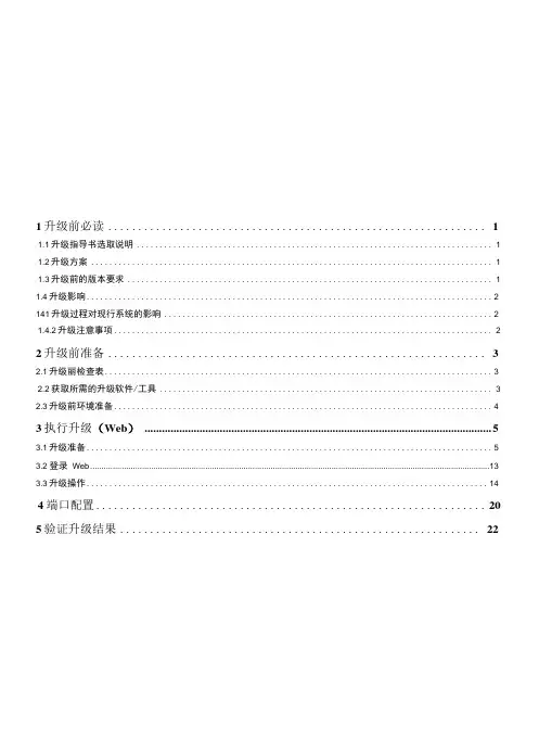
1升级前必读 (1)1.1升级指导书选取说明 (1)1.2升级方案 (1)1.3升级前的版本要求 (1)1.4升级影响 (2)141升级过程对现行系统的影响 (2)1.4.2升级注意事项 (2)2升级前准备 (3)2.1升级丽检查表 (3)2.2获取所需的升级软件/工具 (3)2.3升级前环境准备 (4)3执行升级(Web) (5)3.1升级准备 (5)3.2 登录Web (13)3.3升级操作 (14)4端口配置 (20)5验证升级结果 (22)1.1升级指导书选取说明升级前,需获得客户许可,使用PC连接客户的电源设备;在未经客户允许的情况下, 禁止升级客户电源设备软件。
1.2升级方案设备的so库协议包可以通过Web方式进行加载升级。
1.3升级前的版本要求表i・i升级前的版本要求Q说明当前系统的软件版本,可以通过Web进行查看,查看方法请参考5验证升级结果。
1.4升级影响1.4.1升级过程对现行系统的影响对业务的影响在升级完软件时,监控模块会重新启动,约3分钟。
对网管系统的影响无1.4.2升级注意事项升级过程屮,如果岀现升级失败等异常情况,不能断电复位,应按照指导屮的界常处理情况操作,或联系本地TAC。
2升级前准备2.1升级前检查表表2-1升级前检查表ffll 说明“耗时"依不同环境(包括现场数据量.服务器性能等原因)会存在一定差异。
表格中的〃检查 结果〃由现场升级人员填写。
2.2获取所需的升级软件/工具文件列表表2-2待下载的文件列表文件包名称说明SCC800 V100R001C90SPCXXX_SMU02B_SQ.zip设备的so 库协议包下载方法步骤1进入网站主页http://s 叩,单击“中文”或者"English ”选择合适的语 言。
步骤2单击“登录”,输入用户名、密码登录。
登录成功进入华为技术支持主界面。
步骤3选择“技术支持 > 产品软件 > 网络能源 > 通信能源 > 站点电源 > 能源其他> SMU”,根据实际需要下载相应版本的软件包,如下图所示。
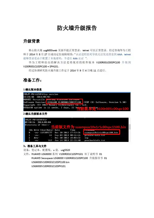
防火墙升级报告升级背景核心防火墙usg6650web页面不能正常登录,telnet可以正常登录。
经过咨询华为工程师于2014年8月27日成功定位故障原因:“认证进程挂死导致无法发送消息到AAA,telnet 能够登录是由于配置了本地密码,不进行AAA认证”。
华为工程师给出的解决方法是将现有的软件版本V100R001C00SPC100升级到V100R001C10SPC100 + SPH101。
经过协调研究防火墙升级工作定于2014年9月4日晚11点进行。
准备工作:1:确认版本信息当前版本是v100r001c00spc100 2:确认当前版本文件当前版文件为suampua10v1r1c00spc1100.bin3:准备工具与文件设备:笔记本、配置线、u盘、usg5320文件:HUAWEI USG6000系列V100R001C10SPH101 补丁说明书01HUAWEI Secospace USG6000 V100R001C10SPC100 升级指导书01USG6000V100R001C10SPC100.binUSG6000V100R001C10SPH101升级步骤:一:备份cf卡所有文件并导入新版本的启动软件。
1:将u盘插入防火墙usb接口,出现udisk0: filesystem status is OK.提示时说明u盘挂载成1200640 KB total (244544 KB free)执行copy命令,将cf卡中的文件备份到u盘里采用同样的方法,将其他的文件备份到u盘里。
4:执行copy命令,将u盘中的启动文件导入到设备cf卡的根目录#必须是根目录,否则会导致升级失败#二:重启设备1:确认设备的当前的配置文件、版本文件和下次启动时加载的配置文件、版本文件,如下图。
2:使用startup system-software命令指定下次启动时加载的版本文件,如下图。
3:升级前确定执行display startup 查看startup信息,如下图。
SoftCo V100R002 升级指导书(仅供内部使用)拟制: Drafted by: 周学艺 00101134 日期: Date: 2009-01-13 审核:Reviewed by: 日期: Date: 审核:Reviewed by: 日期: Date: 批准:Approved by:日期: Date:华为技术有限公司Huawei Technologies Co., Ltd.版权所有 侵权必究 All rights reserved修订记录目录1 产品简介 (5)1.1 功能简介 (5)1.2 面板介绍 (5)1.3 接口板介绍 (7)1.4 系统软件介绍 (8)2 版本加载 (13)2.1 加载前的准备工作 (13)2.2 加载过程 (17)2.3 加载后的验证工作 (25)2.4 数据备份操作 (25)3 版本升级 (26)3.1版本程序在线升级 (26)3.2版本程序加载升级 (28)3.3 数据恢复操作 (29)4 常见问题 (29)5 附件 (30)SoftCo V100R002升级指导书关键词:SoftCo、TFTP摘要:此文档主要介绍了SoftCo5816、SoftCo9500的版本加载方法、升级操作指导以及一些常见问题的定位和排除方法等内容。
重点在于版本加载的介绍,对于其它数据及业务配置请参考《SoftCo V100R002 开局指导书》。
缩略语清单:1 产品简介1.1 功能简介SoftCo系列语音交换机是一个小型的NGN系统,集NGN的各种部件功能如SoftSwitch(软交换) 、TG(中继媒体网关) 、SG(信令网关) 、MRS(媒体资源服务器)于一体,专门用于向非营运网络(企业网、政务网)提供语音业务。
SoftCo自带模拟POTS用户,可通过IAD、MGCP、UA5000等设备接入普通用户,可以直接接入SIP Phone,也可以下挂传统PBX或集团电话保护用户原有投资。
HUAWEIALE-CL00 V100R001C92B170版本升级指导书Huawei Technologies Co., Ltd.华为技术有限公司All rights reserved版权所有侵权必究目录1版本要求 (3)1.1历史版本信息表. (3)1.2升级环境要求 (3)1.3升级文件清单 (3)2升级准备 (3)2.1检查升级环境是否符合要求 (3)2.2获取/检查升级软件包 (3)3升级说明 (3)4升级操作 (4)4.1正常升级(首选升级方法) (4)4.1.1升级大包 (4)4.2强制升级 (4)4.2.1升级大包 (4)5升级验证 (6)5.1版本检查1.开机后进入设置-〉关于手机-〉版本号,查看版本号正确,如图: (6)5.2基本功能遍历 (6)6注意 (6)6.1注意事项一 (6)6.2注意事项二 (6)1 版本要求1.1 历史版本信息表.1.2 升级环境要求适用于手机软件,需要使用MICRO SD卡升级或usb升级1.3 升级文件清单2 升级准备2.1 检查升级环境是否符合要求检查MICRO SD卡是否可以读写2.2 获取/检查升级软件包目录结构相同为:dload\UPDATE.APP3 升级说明升级方式有两种:强制升级和正常升级强制升级由于不需要开机,因此适合在无法正常开机的情况下使用(包括无法开机,无法进入待机界面等).正常升级需要开机并且能够进入设置模块。
4 升级操作4.1 正常升级(首选升级方法)4.1.1升级大包步骤一:准备一张SD卡,建议使用Sandisk, Kingstone, 或Kingmax,大小建议在2G 以上。
步骤二:格式化SD卡(可选)。
步骤三:拷贝大包路径下的UPDATA.APP 到SD卡dload\UPDATA.APP。
步骤四:检查SD卡根目录下是否有dload\UPDATA.APP。
步骤五:将SD卡插入手机开机,在主屏进入设置-〉系统更新-〉本地升级-〉SD卡升级,如需备份数据,请选择备份数据;之后,开始升级。
OptiX 2500+ (Metro 3000)产品软件升级指导书华为技术有限公司版权所有侵权必究修订记录目录1概述 (6)1.1升级工具 (6)1.2升级必读资料 (6)1.3升级先后顺序 (6)1.4软件获取途径 (7)1.5升级流程规范........................................................................................ 错误!未定义书签。
2SCC板软件升级.. (7)2.1升级前准备工作 (7)2.2升级顺序 (8)2.3升级注意事项 (8)2.4各版本之间升级方式说明 (9)2.4.1Optix 2500+主流主机软件升级方式汇总表 (9)2.4.2各种升级方式详细描述 (11)2.5升级后重点检查内容 (14)2.6主机软件加载异常问题处理 (15)2.6.1问题1:主机软件升级后进入安装态 (15)2.6.2问题2:主机软件无法加载 (15)2.6.3问题3:SS62SCC板的FPGA加载问题 (17)2.6.4问题3:低阶业务过多导致升级后校验无法通过 (17)3业务板的单板软件及FPGA升级 (18)3.1升级前准备工作 (18)3.2升级顺序 (20)3.3升级步骤 (20)3.4升级注意事项 (22)3.5升级后重点检查内容 (22)3.6单板软件加载异常问题处理 (23)3.6.1问题1单板软件加载不成功 (23)3.7单板FPGA加载异常问题处理 (24)3.7.1问题1:单板软件及FPGA加载错误问题 (24)4数据单板升级指导书 (25)4.1ATM处理板.......................................................................................... 错误!未定义书签。
4.1.1升级前准备工作 .......................................................................... 错误!未定义书签。

HUAWEI ASG2000 应用安全网关 V100R001C10SPC200升级指导书文档版本 01发布日期2016-03-03华为技术有限公司版权所有© 华为技术有限公司2016。
保留一切权利。
非经本公司书面许可,任何单位和个人不得擅自摘抄、复制本文档内容的部分或全部,并不得以任何形式传播。
商标声明和其他华为商标均为华为技术有限公司的商标。
本文档提及的其他所有商标或注册商标,由各自的所有人拥有。
注意您购买的产品、服务或特性等应受华为公司商业合同和条款的约束,本文档中描述的全部或部分产品、服务或特性可能不在您的购买或使用范围之内。
除非合同另有约定,华为公司对本文档内容不做任何明示或默示的声明或保证。
由于产品版本升级或其他原因,本文档内容会不定期进行更新。
除非另有约定,本文档仅作为使用指导,本文档中的所有陈述、信息和建议不构成任何明示或暗示的担保。
华为技术有限公司地址:深圳市龙岗区坂田华为总部办公楼邮编:518129网址:目录1 升级前必读 (1)1.1 升级场景说明 (1)1.2 升级方式介绍 (2)1.3 升级流程 (3)1.4 升级影响 (6)1.4.1 升级过程中对现行系统的影响 (6)1.4.2 升级后对现行系统的影响 (6)1.5 注意事项 (7)2 ASG设备版本升级 (8)2.1 升级前准备 (8)2.1.1 准备升级环境 (8)2.1.2 获取升级所需的文件 (9)2.1.3 查询当前版本软件的信息 (10)2.1.4 确认License的使用情况 (10)2.1.5 查询设备的运行状态 (11)2.1.6 查询业务的运行情况 (12)2.1.7 保存和备份重要数据 (13)2.2 单机环境下的版本升级 (16)2.2.1 通过Web方式升级 (16)2.3 双机热备环境下升级ASG版本软件 (21)2.3.1 简介 (21)2.3.2 升级过程 (21)2.4 升级结果验证 (23)2.4.1 检查升级后的版本软件信息 (23)2.4.2 检查License的状态 (23)2.4.3 检查设备的运行状态 (24)2.4.4 检查配置是否恢复 (24)2.4.5 检查业务是否正常 (25)2.5 版本回退 (26)3 ASG管理中心升级 (27)3.1 升级前准备 (27)3.1.1 获取升级所需的安装包 (27)3.1.2 保证升级所需磁盘空间 (28)3.1.3 查询当前版本软件的信息 (28)3.1.4 查询采集器的运行状态 (28)3.1.5 查询当前管理的设备状态 (28)3.1.6 查询业务的运行情况 (28)3.1.7 分布式部署的版本信息 (30)3.2 集中式部署升级 (30)3.2.1 升级ASG管理中心 (30)3.2.2 验证升级结果 (33)3.2.3 升级异常处理 (34)3.3 分布式部署升级 (35)3.3.1 升级日志采集器 (35)3.3.2 验证升级结果 (38)3.3.3 采集器升级异常处理 (39)3.3.4 升级ASG管理中心服务器 (39)4 附录A:通过BootROM方式升级版本软件 (40)4.1 背景信息 (40)4.2 升级流程 (41)4.3 升级操作 (41)5 附录B:通过Console口搭建升级环境 (46)5.1 操作步骤 (46)5.2 故障处理 (48)5.2.1 忘记Console口密码的解决方法 (48)6 附录C:如何解决升级后自定义应用协议分类缺失 (50)7 附录D:申请License文件 (53)8 附录E:软件完整性校验 (56)9 附录F:升级记录表 (57)10 附录G:缩略语 (59)11 附录H:手动增加手机类型对象定义 (60)1 升级前必读关于本章1.1 升级场景说明1.2 升级方式介绍1.3 升级流程1.4 升级影响1.5 注意事项1.1 升级场景说明ASG主要包括两部分:ASG设备、ASG管理中心。
Release Notes PowerFlex 700 Drive w/Vector Control Option (Revision 40.001)These release notes correspond to the firmware version 40.001 for PowerFlex® 700 drives using the new Variable Boost V oltage function. This version of firmware incorporates all functions included in PowerFlex 700 drive firmware version 6.001.Determining Firmware Revision Level To determine the firmware version for a PowerFlex 700 Drive, view parameter 29 [Control SW Ver].Firmware Upgrade Procedure This section describes procedures to flash upgrade your drive firmware. Downloads are provided on the Allen-Bradley Web Updates site located at /support/abdrives/webupdate. For a detailed explanation of the flash procedure, refer to /support/abdrives/ powerflex700vc/phase1/firmware/index.html.Important:Once a flash update has been started, do not remove drive power until the download is complete and the drive has beenreset. If power is removed during Boot Flash, the drive may bepermanently damaged. A drive that has been damaged in thisway cannot be repaired. If power is removed duringApplication Flash, the drive will remain in Boot and can bereflashed.1.Remove/disconnect any HIMs before proceeding.2.Install the “v40.001 Flash Kit” from the Allen-Bradley Web Updates site.This automatically installs the latest version of the ControlFLASH utility on your computer. ControlFLASH, DriveExplorer or DriveExecutive can now be used to update the drive using the following instructions.Using ControlFLASHImportant:This method requires RSLinx.unch ControlFLASH (if it is not already running).2.Follow the screen prompts until the flash procedure is completed and thenew firmware version is displayed.ATTENTION: Risk of drive damage exists if drive power isremoved during the Boot Flash segment of the upgrade/download.To guard against damage, Do Not Remove Power to the driveuntil the download is complete and the drive has been reset.2PowerFlex 700 Drive w/Vector Control Option (Revision 40.001)Using DriveExplorer Lite/Full1.Exit the ControlFLASH program (if it is running) and launchDriveExplorer. Make a connection to the drive.2.In the DriveExplorer treeview, select the appropriate drive. Then selectthe Information icon.3.On the Properties screen, select the “Details” tab.4.Select “Flash Update” and follow the screen prompts until the procedureis completed and the new firmware version is displayed.Using DriveExecutiveImportant:This method requires RSLinx.1.Exit the ControlFLASH program (if it is running) and launchDriveExecutive. Make a connection to the drive.2.In the DriveExecutive treeview, select the appropriate drive. Then selectthe Information icon.3.On the Properties screen, select “Component Details.”4.Select “Flash Update” and follow the screen prompts until the procedureis completed and the new firmware version is displayed. Enhancements This section describes the enhancements included in this revision:Variable Boost Voltage FunctionThe Variable Boost V oltage function provides a reliable means of selectingthe appropriate fixed-value boost voltage in V/Hz mode to allow a drive(s)to start a load with a high variable level of breakaway torque and to allow adrive(s) to start into a rotating load in order to provide a controlleddeceleration when shutting down.Configuration and OperationTo enable the variable boost voltage function:1.Set [Motor Cntl Sel], parameter 53 to 2 “Custom V/Hz”2.Set bit 0 “VB Enable” of parameter 575 [Boost Config] to “1”Bit 0 “VB Enabled” of parameter 576 [Boost Status] is set to “1” when theabove two conditions are met.Immediately following a valid drive run command, the drive produces themotor voltage specified in [Start Boost], parameter 69 at the frequencyspecified in [Boost Frequency], parameter 566. The actual motor boostvoltage can be viewed in [Boost V oltage], parameter 560. Parameter 23[Speed Reference], regardless of the speed reference source, and parameter2 [Commanded Speed], regardless of the linear ramp and S-curve settings,are held at the value of [Boost Frequency]. The boost voltage (in [BoostV oltage]) ramps up at the value specified in [Start Boost], parameter 69 atthe rate set in [Boost Accel Rate], parameter 564 (in volts per second).PowerFlex 700 Drive w/Vector Control Option (Revision 40.001)3This occurs until the value of [Boost Maximum], parameter 563 is reached or one of the variable boost voltage trigger events occurs and bit 2 “Triggered” of [Boost Status], parameter 576 is set to “1” (true). When the maximum boost voltage value is reached or a trigger event occurs, [Boost V oltage] ramps down at the value specified in [Boost Decel Rate], parameter 565 (in volts per second) to the voltage value set in [Boost Minimum], parameter 562. Whenever the drive is stopped, the value of [Boost V oltage] is reset to the value of [Start Boost]. Coincident with a voltage trigger event, the commanded speed of the drive ramps according to the linear ramp and S-curve settings. Typically, the selected speed reference will be greater than the value set in [Boost Frequency], but is not required. Boost voltage trigger event sources are individually enabled via bits in [Boost Config], parameter 575 with a corresponding status bit displayed in [Boost Status]. The boost voltage trigger events are derived from the following sources:•The level of [Filt Flux Curr], parameter 570•The slope and level of [Current Rate], parameter 571•The level of [Output Freq], parameter 1•The level of [Boost V oltage], parameter 560 (always enabled) [Current Rate], Parameter 571 is the derivative of the value of [Output Current], parameter 3 passed through a first order low-pass filter with a cutoff frequency equal to the value of [Rate Lag Freq], parameter 574. The trigger event associated with this value is enabled by setting bit 1 “Current Rate” in [Boost Config]. The trigger condition is defined by the level of [Current Thresh], parameter 573 with a hysteresis band equal to the value of [Current Hyst], parameter 572. In addition, the slope of [Current Rate] is set to either rising or falling via bit 2 “Rising Edge” in [Boost Config].4PowerFlex 700 Drive w/Vector Control Option (Revision 40.001)If these trigger conditions are met, bit 3 “Current Trig” in [Boost Status] isset to “1” (true).[Filt Flux Curr], Parameter 570 is the drive calculated value of the unfilteredmotor flux current passed through a first order low-pass filter with the cutofffrequency equal to the value specified in [Flux Lag Freq], parameter 569.The trigger event associated with this value is enabled by setting bit 3 “FluxLevel” in [Boost Config]. The trigger condition is defined by the level of[Flux Threshold], parameter 568. If [Filt Flux Curr] is greater than or equalto the value of [Flux Threshold] then bit 4 “Flux Trigger” in [Boost Status]is set to “1” (true).The third trigger source is derived from the value of [Output Freq],parameter 1 and is enabled via bit 4 “Minimum Freq” in [Boost Config]. Ifthe value of [Output Freq] is less than or equal to the value of [Boost MinFreq], parameter 567 then bit 5 “Freq Trigger” of [Boost Status] is set to “1”(true).If the boost voltage (set in [Boost V oltage]) reaches the value of [BoostMaximum], parameter 563 before any of the other trigger events cause theboost voltage to ramp down, then bit 6 “Max Boost” in [Boost Status] is setto “1” (true) and the boost voltage ramps down at the rate specified in[Boost Decel Rate], parameter 565 (in volts per second) to the value set in[Boost Minimum], parameter 562. This trigger condition is always enabledand therefore has no corresponding bit in [Boost Config] and is notconstrained by the time set in [Boost Time], parameter 561.If any of the preceding trigger conditions are met and bit 0 “VB Enable” in[Boost Status] is set to “1” (true), then bit 2 “Triggered” in [Boost Status] isset to “1” (true). This bit and the trigger status bits are cleared (set to false)at the moment the drive starts. You may clear the individual trigger statusbits at any time by toggling the corresponding enable bit in [Boost Config].All trigger status bits are cleared if bit 0 “VB Enable” in [Boost Config] iscleared (set to “0”).Following a valid drive run command, the trigger sources, with theexception of the “Max Boost” trigger (based on the value of [BoostMaximum]), are not enabled until the amount of time specified in [BoostTime], parameter 561 has expired. When the value of [Boost V oltage]reaches the value of [Boost Maximum], the boost voltage begins rampingdown and the output frequency is released from the value set in [BoostFrequency], regardless of [Boost Time].PowerFlex 700 Drive w/Vector Control Option (Revision 40.001)5New ParametersThe following parameters are added for this firmware version and support the Variable Boost V oltage function:F i l eG r o u pN o .Parameter Name & DescriptionValuesR e l a t e dB o o s tC o n f i g560[Boost Voltage]Displays the output value of thevoltage-axis intercept of the V/Hz curve.When the variable boost function is enabled the value of [Boost Voltage] is ramped up/down according to the settings of the variable boost function when the drive is running.[Boost Voltage] is equal to parameter 69 [Start Boost] when the drive is stopped or when bit 0 “VB Enable”, of parameter 575 [Boost Config], is set to “0”.Default:Min/Max:Units:Read Only0.0/Drive Rated Volts 0.1 VAC 561[Boost Time]Sets the time delay for which the variable voltage boost trigger becomes activefollowing a drive start.The [Boost Time] begins counting down when the drive enters the run state. Valid trigger conditions may only be met in the time following the expiration of the [Boost Time] to cause a trigger event. This time delay does not affect the trigger condition associated with parameter 563 [Boost Maximum].Default:Min/Max:Units: 1.0 Secs 0.0/100.0 Secs 0.1 Secs 562[Boost Minimum]Sets the minimum voltage boost level for the variable boost voltage function.If parameter 560 [Boost Voltage] reaches the value of parameter 563 [Boost Maximum] or one of the variable boost voltage trigger events occurs, then [Boost Voltage] decelerates at the rate corresponding to the value set in parameter 565 [Boost Decel Rate].Default:Min/Max:Units:Based on Drive Rating 0.0/563 [Boost Maximum]0.1 VAC 563[Boost Maximum]Sets the maximum voltage boost level for the variable boost voltage function.If parameter 560 [Boost Voltage] reachesthe value of [Boost Maximum] then [Boost Voltage] decelerates at the rate corresponding to the value of parameter 565 [Boost Decel Rate].Default:Min/Max:Units:Based on Drive Rating 69 [Start Boost] /71 [Break Voltage]0.1 VAC 564[Boost Accel Rate]Sets the rate of acceleration of parameter 560 [Boost Voltage] for the variable boost voltage function.Default:Min/Max:Units:0.75 V/s 0.01/327.67 V/s0.01 V/s 565[Boost Decel Rate]Sets the rate of deceleration of parameter 560 [Boost Voltage] for the variable boost voltage function following a trigger event.Default:Min/Max:Units: 6.00 V/s 0.01/327.67 V/s0.01 V/s 566[Boost Frequency]Sets the initial frequency reference forthe variable boost voltage function.Default:Min/Max:Units:0.8 Hz 0.5/10.0 Hz 0.1 Hz6PowerFlex 700 Drive w/Vector Control Option (Revision 40.001)B o o s tC o n f i g567[Boost Min Freq]Sets the frequency reference trigger level for the variable boost voltage function.Bit 5 “Freq Trigger” of parameter 576 [Boost Status] is set to 1 when the value of parameter 1 [Output Freq] falls below [Boost Min Freq].To enable this threshold and trigger event set bits 0 "VB Enable" and 4 "Minimum Freq" in parameter 576 [Boost Config] to “1”.Default:Min/Max:Units:0.5 Hz1.0/10.0 Hz0.1 Hz 568[Flux Threshold]Sets the flux current trigger level for the variable boost voltage function.Bit 4 “Flux Trigger” of parameter 576 [Boost Status] is set to “1” when the value of parameter 570 [Filt Flux Curr] exceeds the value of this parameter.To enable this threshold and trigger event set the bits 0 "VB Enable" and 3 "Flux Level" in parameter 576 [Boost Config] to “1”.Default:Min/Max:Units:50% Drive Rated Amps 0.0/690.00.1 Amps 569[Flux Lag Freq]Sets the lag (cutoff) frequency of theparameter 5 [Flux Current] low pass filter.The output of this filter is displayed in parameter 570 [Filt Flux Curr].Default:Min/Max:Units:0.60 Rads/Sec.0.01/100.00 Rads/Sec.0.01 Rads/Sec.570[Filt Flux Curr]Filtered value of parameter 5 [FluxCurrent].Parameter 569 [Flux Lag Freq] sets the cutoff frequency of the low-pass filter.Default:Min/Max:Units:Read Only 0.0 / 3276.70.1 Amps571[Current Rate]Output current rate of change.Default:Min/Max:Units:Read Only–/+1000.0 Amps/Sec.0.1 Amps/Sec.572[Current Hyst]Sets the hysteresis level aroundparameter 573 [Current Thresh] for the variable boost voltage function.Default:Min/Max:Units:0.0 Amps/Sec.–/+100.0 Amps/Sec.0.1 Amps/Sec.573[Current Thresh]Sets the trigger level of parameter 571 [Current Rate] for the variable boostvoltage function. The trigger is not active until the time specified in parameter 561 [Boost Time] time has expired following a drive start.•When bit 2 “Rising Edge” ofparameter 575 [Boost Config] = “0”, the value of parameter 571 [Current Rate] must first fall below the value of [Current Thresh] + [Current Hyst], then fall below the value of [Current Thresh] in order to cause a boost voltage trigger event.•When bit 2 “Rising Edge” ofparameter 575 [Boost Config] = “1”, the value of [Current Rate] must first rise above the value of [Current Thresh] - [Current Hyst], then rise above the value of [Current Thresh] in order to cause a boost voltage trigger event.Default:Min/Max:Units:–25.0 A/s–/+1000.0 Amps/Sec.0.1 Amps/Sec.PowerFlex 700 Drive w/Vector Control Option (Revision 40.001)7Motor Overload MemoryThis is an enhanced version of the v4.002 Motor Overload Memory function.In v4.002, the ability to preserve the value of [Motor OL Count], parameter 220 through a power cycle was added and enabled through testpoint (#629).Set [234 Testpoint 1 Sel] = 629 and then set [235 Testpoint 1 Data] to 1 or Set [236 Testpoint 2 Sel] = 629 and then set [237 Testpoint 2 Data] to 1.In earlier software versions the value of [Motor OL Count] was NOT maintained through a drive reset. That enhancement is now offered. The testpoint method will still work, but the preferred method is to set [Motor OL Mode], parameter 50.8PowerFlex 700 Drive w/Vector Control Option (Revision 40.001)Disable Synchronous PWMAt high output frequencies (if [Motor Cntl Sel] is NOT set to “4, FVCVector”) the PWM frequency is varied to keep it a multiple of the outputfrequency (synchronous PWM):PWM Frequency = PWM Ratio × Output FrequencyPWM Ratio = 27, 24, 21, 18, 15, 12, 9, or 6A bit has been added to [Compensation], parameter 56 to optionally disablesynchronous PWM.PowerFlex 700 Drive w/Vector Control Option (Revision 40.001)9“Manual Mode” and “Fast Braking” StatusStatus bits have been added to indicate that a device has “Manual” control of the speed reference and that a “Fast Brake” stop is in progress.Refer to “Auto/Manual Examples” in the User Manual for an explanation of “Manual” control.New Speed Error Filter Bandwidth ParameterA separate adjustment for the speed error filter bandwidth was added to aid in configuring high inertia systems.S P E E D C O M M A N DS p e e d R e g u l a t o r448[Spd Err Filt BW]Sets the bandwidth of a speed error filter used in FVC Vector mode. Setting 0.0 disables the filter.Default:Min/Max:Units:200.0 R/s 0.0/2000.0 R/s0.1 R/s 053FV v6U.S.Allen-BradleyDrivesTechnicalSupport-Tel:(1)262.512.8176,Fax:(1)262.512.2222,Email:*****************,Online:/support/abdrivesPublication 20B-RN006A-EN-P – February, 2008Copyri g ht © 2008 Rockwell Automation, Inc. All ri g hts reserved. Printed in USA.。
OptiX Metro 500 V100R001软件升级指导书拟制:曾凡旭日期:2003年03月28日审核:日期:审核:日期:批准:日期:华为技术有限公司目录1产品软件情况 (3)1.1产品上支持的软件 (3)1.2软件版本情况 (3)2软件升级指导 (3)2.1主机软件升级 (4)2.1.1主机软件升级步骤 (4)2.1.2主机软件加载方法 (5)2.2BIOS升级 (5)2.2.1扩展BIOS软件升级步骤 (6)2.2.2扩展BIOS软件加载方法 (6)2.3FPGA升级 (6)2.3.1FPGA软件升级步骤 (6)2.3.2FPGA软件加载方法 (7)OptiX Metro 500 V100R001软件升级指导书1 产品软件情况1.1 产品上支持的软件Metro 500 V100R001上支持的软件有:主机软件、基础BIOS、扩展BIOS、FPGA;除基础BIOS外,其他均可在线升级。
无单板软件、单板BIOS、单板FPGA。
1.2 软件版本情况单板FPGA版本:110/120/130主机软件的版本为:ne5.17.01.10P05。
//备注:目前网上主流版本ne5.17.01.10P01/ ne5.17.01.10P04/ ne5.17.01.10P05。
BIOS软件版本:8.02.02/03/04/05。
扩展BIOS版本:9.02.01网管软件的版本为:V100R004版本以及以上版本Navigator:5.01以及以上版本2 软件升级指导目前主机软件有ne5.17.01.10P01/P04/P05。
FPGA软件有:110/120/130。
扩展BIOS版本为9.02.01,由于扩展BIOS是用来完善基础BIOS功能的,所以早期发货没有扩展BIOS,后续版本需要加载。
升级时,主机软件、FPGA和扩展BIOS的加载顺序没有特别要求,建议软件加载顺序:扩展BIOS、主机软件、FPGA。
2.1 主机软件升级Metro 500有两套主机软件,分别为“nsf1”、“nsf2”,分别存放在两片FLASH中,主机软件后缀名为“.hwx”。
1 升级前必读1.1 升级前的版本要求表1-1升级前的版本要求1.2 升级影响如果需要从低版本升级到V100R003C00SPC301版本,您需要认真阅读本章,了解升级可能对现有系统造成的影响。
1.2.1 升级过程对现行系统的影响对业务的影响业务中断时间为升级时间、配置业务时间和重新启动时间的总和。
对网络通信的影响重新启动时,单板和网管之间的通信会中断。
1.2.2 升级后对现行系统的影响无1.3 升级注意事项●请确保同时升级了bootrom。
●因S2300设备的flash存储格式在V100R003C00SPC100版本做过重大的修改,V100R002各版本升级到V100R003C00时,不建议使用bootrom升级方式,推荐通过命令行方式升级的方式。
加载完V100R003C00SPC100版本及其之后的版本后第一次重启动时,软件会对flash进行重新格式化并删除原V100R002版本的VRP软件(V1R3的版本及配置文件会保留),此时请不要复位单板或断电,以防数据丢失。
由于Flash格式发生了变化,请在升级前备份Flash中重要数据。
(配置文件不用单独备份,系统会自动同步)2 升级流程图2-1升级流程图注:后续举例都以升级到V100R003C00SPC100为例。
3 升级前准备3.1 升级前检查表表3-1升级前检查表3.2 查看当前VRP系统软件版本使用display version命令查看S2300正在运行的VRP系统软件的版本。
<Quidway> display versionHuawei Versatile Routing Platform SoftwareVRP (R) Software, Version 5.30 (S2300 V100R002C02SPC002)Copyright (C) 2007-2008 Huawei Technologies Co., Ltd.Quidway S2309TP-EI uptime is 0 day, 0 hour, 2 minutes[Slot 0] E8FE uptime is 0 day, 0 hour, 2 minutesStartup time :2008/01/01 00:21:3864M bytes DDR Memory16M bytes FLASHPcb Version : CX22E8FE REV BBasic BOOTROM Version : 113 Compiled at May 6 2009, 13:46:43Advanced BOOTROM Version : 115 Compiled at May 6 2009, 13:48:53Software Version : VRP (R) Software, Version 5.30 (S2300 V100R002C02SPC002)3.3 检查设备运行状态使用display device命令查看S系列设备工作状态。
ALE-CL00 V100R001C92B230
版本升级指导书
Huawei Technologies Co., Ltd.
华为技术有限公司
All rights reserved
版权所有侵权必究
目录
1版本要求 (4)
1.1升级环境要求 (4)
1.2升级文件清单 (4)
2升级准备 (4)
2.1检查升级环境是否符合要求 (4)
2.2获取/检查升级软件包 (4)
3升级说明 (4)
4升级操作 (4)
4.1正常升级(首选升级方法) (4)
4.2强制升级 (5)
5升级验证 (7)
5.1版本检查1.开机后进入设置-〉关于手机-〉版本号,查看版本号,如图参考: (7)
5.2基本功能遍历 (7)
6注意 (7)
6.1注意事项一 (7)
6.2注意事项二 (7)
1 版本要求
1.1 升级环境要求
适用于手机软件,需要使用MICRO SD卡升级或usb升级
1.2 升级文件清单
2 升级准备
2.1 检查升级环境是否符合要求
检查MICRO SD卡是否可以读写
2.2 获取/检查升级软件包
目录结构相同为:
dload\UPDATE.APP
3 升级说明
升级方式有两种:强制升级和正常升级
强制升级由于不需要开机,因此适合在无法正常开机的情况下使用(包括无法开机,无法进入待机界面等).正常升级需要开机并且能够进入设置模块。
4 升级操作
4.1 正常升级(首选升级方法)
步骤一:准备一张SD卡,建议使用Sandisk, Kingstone, 或Kingmax,大小建议在2G 以上。
步骤二:格式化SD卡(可选)。
步骤三:拷贝大包路径下的UPDATE.APP 到SD卡dload目录下。
步骤四:拷贝小包路径下的UPDATE_VENDOR.APP 到SD卡dload目录下。
步骤五:检查SD卡根目录文件夹dload下是否有\UPDATE.APP和
UPDATE_VENDOR.APP
步骤六:将SD卡插入手机开机,进入设置-〉关于手机-〉系统软件更新-〉本地升级,如需备份数据,请选择备份数据;之后,开始升级。
步骤七:升级过程有进度条显示,待进度条走完后,手机自动重启.
4.2 强制升级
步骤一:准备一张SD卡,建议使用Sandisk, Kingstone, 或Kingmax,大小建议在2G 以上。
步骤二:格式化SD卡(可选)。
步骤三:拷贝大包路径下的UPDATE.APP 到SD卡dload目录下。
步骤四:拷贝小包路径下的UPDATE_VENDOR.APP到SD卡dload目录下。
步骤五:检查SD卡根目录文件夹dload下是否有\UPDATE.APP和
UPDATE_VENDOR.APP
步骤六:手机在关机状态下,插入SD卡,同时按下音量上键+音量下键+开关机键,手机自动进入升级模式,然后开始升级,如图:
步骤七:待进度条走满不动后,手机会自动重启,如果没有请手动拆除电池。
5 升级验证
5.1 版本检查1. 开机后进入设置-〉关于手机-〉版本号,查看版本号,如图参
考:
ALE-CL00 V100R001C92B230
5.2基本功能遍历
开机正常启动,进入待机界面,输入号码能够拨通电话,长按Power键关机,正常掉电。
6 注意
6.1 注意事项一
为了确保升级过程中电池电量充足,建议在升级过程中连接USB线供电。
6.2 注意事项二
升级过程会擦除用户数据,如果有重要内容,建议在升级前先做好备份。