ZB24580-application
- 格式:pdf
- 大小:40.07 KB
- 文档页数:1

桂电智能仪器实验代码(最新l ab 80 00 平台汇编)实验1ORG 0000HAJMP MAINORG 0200HBUFF EQU 60HMAIN:MOV R3,#00HMOV R4,#00H ACALL DISPLAY ACALL KEXAM JZ MAINACALL D10msACALL KEXAMJZ MAINMOV R2,#0DFH MOV DPTR,#8004H MOV A,#00H MOVX @DPTR,A KEY1:MOV DPTR,#8002H MOV A,R2 MOVX @DPTR,A MOV DPTR,#8001H MOVX A,@DPTR CPL AANL A,#0FHJNZ KEY2MOV A,R3 ADD A,#04H MOV R3,AMOV A,R2RR AMOV R2,AJB ACC.0,KEY1AJMP MAINKEY2:CPL AKEY3:RRC AJNC KEY4 INC R4AJMP KEY3KEY4:ACALL DISPLAY ACALL D10ms ACALL KEXAM JNZ KEY4MOV A,R3ADD A,R4MOV BUFF,AKEND:AJMP MAINKEXAM:MOV DPTR,#8002HMOV A,#00HMOVX @DPTR,AMOV DPTR,#8001HMOVX A,@DPTRCPL AANL A,#0FHRETDISPLAY:MOV DPTR,#TABMOV A,60HMOVC A,@A+DPTRMOV DPTR,#8004H MOVX @DPTR,A MOV DPTR,#8002H MOV A,#10HMOVX @DPTR,ARETD10ms:MOV R5,#30H DL:MOV R6,#0FFH DL0:DJNZ R6,DL0 DJNZ R5,DLRETTAB:DB 3FH 06H 66H 07HDB 71H 5BH 6DH 7FHDB 79H 4FH 7DH 6FHDB 5EH 39H 7CH 77HORG 0000HAJMP MAINORG 0100HMAIN: ACALL KEXAM ;检查按键JZ MAIN ;无继续ACALL D10ms ;延时去抖ACALL KEXAMJZ MAINSTART: MOV DPTR,#8002H ;键值分析及选通道MOV A,#0DFHMOVX @DPTR,AMOV DPTR,#8001HMOVX A,@DPTRCPL AANL A,#07HCJNE A,#01H,KEY1 ;INT0AJMP INT0KEY1: CJNE A,#02H,KEY2;INT1AJMP INT1KEY2: CJNE A,#04H,MAINAJMP AUTOINT0: ACALL DISPLAY1MOV A,#0FH ;0-5VMOV DPTR,#9000HMOV R0,#40HMOVX @DPTR,AACALL D10msMOVX A,@DPTRMOV @R0,AACALL CAIACALL DISPLAYACALL KEXAMJZ INT0AJMP STARTINT1: ACALL DISPLAY2MOV A,#0FH ;固定值MOV DPTR,#9001HMOV R0,#40HMOVX @DPTR,AACALL D10msMOVX A,@DPTRMOV @R0,AACALL CAIACALL DISPLAYACALL KEXAMJZ INT1AJMP STARTAUTO: MOV 50H,#2000000 LOPO:ACALL DIOmsDJNZ 50H,L OPOAJMP INTOOAUTO1: MOV 51H,#2OOOOOO LOP1:ACALL DIOmsDJNZ 51H ,L OP1AJMP INT11INTOO:ACALL DISPLAY1MOV A,#OFH ;O-5VMOV DPTR,#9OOOHMOV R0,#40HMOVX @DPTR,AACALL D10msMOVX A,@DPTRMOV @R0,AACALL CAIACALL DISPLAYACALL D10msMOV 53H,#30PPP: ACALL DISPLAY1ACALL DISPLAYACALL DISPLAY1ACALL DISPLAYACALL DISPLAY1ACALL DISPLAYDJNZ 53H,PPPACALL KEXAMJZ AUTO1AJMP STARTINT11:ACALL DISPLAY2MOV A,#0FH ;固定值MOV DPTR,#9001HMOV R0,#40HMOVX @DPTR,AACALL D10msMOVX A,@DPTRMOV @R0,AACALL CAIACALL DISPLAYACALL DIOmsMOV 54H,#30000: ACALL DISPLAY2ACALL DISPLAYACALL DISPLAY2ACALL DISPLAYACALL DISPLAY2ACALL DISPLAYDJNZ 54H,OOOACALL KEXAMJZ AUTOAJMP STARTKEXAM: MOV DPTR,#8004H ;按键判断MOV A,#00HMOVX @DPTR,AMOV DPTR,#8002HMOV A,#00HMOVX @DPTR,AMOV DPTR,#8001HMOVX A,@DPTRCPL AANL A,#0FHRETCAI: MOV A,@R0 ;数据处理MOV B,#51DIV ABMOV 40H,AMOV A,BCLR F0SUBB A,#1AHMOV F0,CMOV A,#10MUL ABMOV B,#51DIV ABJB F0,L OOP2ADD A,#5 LOOP2:MOV 41H,AMOV DPTR,#TAB ;余数 41H 42HMOV A,41HMOVC A,@A+DPTRMOV DPTR,#8004HMOVX @DPTR,AMOV DPTR,#8002HMOV A,#08HMOVX @DPTR,AMOV A,BMOV A,BCLR F0SUBB A,#1AHMOV F0,CMOV A,#10MUL ABMOV B,#51DIV ABJB F0,L OOP3ADD A,#5LOOP3:MOV 42H,ARET DISPLAY:MOV DPTR,#TAB MOV A,40HMOVC A,@A+DPTRMOV DPTR,#8004HMOVX @DPTR,AMOV DPTR,#8002HMOV A,#10HMOVX @DPTR,AACALL D10ms 列表显示个位整数 40H MOV A,#80HMOV DPTR,#8004HMOVX @DPTR,AMOV DPTR,#8002HMOV A,#10H MOVX@DPTR,A ACALL D10ms;小数点ACALL DIOmsMOV DPTR,#TABMOV A,42HMOVC A,@A+DPTRMOV DPTR,#8004HMOVX @DPTR,AMOV DPTR,#8002HMOV A,#04HMOVX @DPTR,AACALL D10msRETDISPLAY1: MOV A,#3FHMOV DPTR,#8004HMOVX @DPTR,AMOV DPTR,#8002HMOV A,#20HMOVX @DPTR,ALCALL D10msRETDISPLAY2: MOV A,#06HMOV DPTR,#8004HMOVX @DPTR,AMOV DPTR,#8002HMOV A,#20HMOVX @DPTR,ALCALL D10msRETD10ms: MOV R5,#03H ;延时 10 DL: MOV R6,#0FFHDL0: DJNZ R6,DL0DJNZ R5,DLRETTAB: DB 3FH,06H,5BH,4FHDB 66H,6DH,7DH,07HDB 7FH,6FH,77H,7CHDB 39H,5EH,79H,71H实验4ORG 0000HAJMP KEYPRORG 0200HKEYPR:MOV R3,#00H ;列寄存器MOV R4,#00H ;行寄存器ACALL KEXAMJZ KENDACALL D10msACALL KEXAMJZ KENDMOV R2,#0DFH ;扫描初值KEY1:MOV DPTR,#8004HMOV A,#00HMOVX @DPTR,AMOV DPTR,#8002H ;送列码地址MOV A,R2MOVX @DPTR,A ;扫描第一列MOV DPTR,#8001H ;送行码地址MOVX A,@DPTRCPL AANL A,#0FHJNZ KEY2 ;有键按下,求行值MOV A,R3 ;无键按下,列加4ADD A,#04HMOV R3,AMOV A,R2 ;求下一列扫描值RR AMOV R2,AJB ACC.0,KEY1 ;判断是否已全扫描AJMP KENDKEY2:CPL A ;恢复行模型KEY3:RRC AJNC KEY4INC R4AJMP KEY3KEY4:ACALL DIOmsACALL KEXAMJNZ KEY4MOV A,R3ADD A,R4MOV 60H,A ;键值存入60HLO:CJNE A,#00H,L1MOV DPTR,#DLTABMOV A,30HCJNE A,#05,ADDF1MOV 30H,#00HLJMP ADDF2ADDF1:INC 30HADDF2:MOVC A,@A+DPTRMOV 31H,ADLTAB:DB 01H,20H,50H,80H,0A0HL1:CJNE A,#0F H,L2 ;锯齿波LS0: ACALL DISPLAY MOV DPTR,#9000H MOV A,#00HLS1:MOVX @DPTR,A INC AACALL DELAYCJNE A,#0FFH,LS1 ACALL DELAY ACALL DISPLAY ACALL KEXAMJZ LS0AJMP KEND KEND:ACALL DISPLAY精品资料LJMP KEYPRL2:CJNE A,#OE H,L3LS2: ACALL DISPLAYMOV DPTR,#9000HMOV A,#00HMOV R0,#200LS3: ACALL DELAYMOVX @DPTR,A INCACJNE A,#0FFH,LS3 LS4: ACALL DELAYDEC AMOVX @DPTR,ACJNE A,#00H,LS4DJNZ R0,LS3ACALL DISPLAYACALL KEXAMJZ LS2AJMP KENDL3:CJNE A,#0D H,L4LS5:ACALL DISPLAYMOV A,#00MOV R0,ALS6: MOV DPTR,#TZSB MOV A,R0MOVC A,@A+DPTRMOV DPTR,#9000HMOVX @DPTR,AACALL DELAYINC R0CJNE R0,#32,LS6ACALL DISPLAYACALL KEXAMJZ LS5AJMP KENDL4:CJNE A,#0CH,KEND ;三角波;正弦波;方波精品资料ACALL DISPLAYMOV R0,#200LS7: ACALL DISPLAYMOV A,#00MOV DPTR,#9000H MOVX @DPTR,A ACALLDELAYMOV A,#255MOVX @DPTR,AACALL DELAYDJNZ R0,LS7ACALL D10msACALL DISPLAYACALL KEXAMJZ LS7AJMP KENDDISPLAY:MOV DPTR,#TAB显示子程序MOV A,60HMOVC A,@A+DPTRMOV DPTR,#8004HMOVX @DPTR,AMOV DPTR,#8002HMOV A,#01HMOVX @DPTR,ARETD10ms:MOV R5,#03H ;延时 10 毫秒DL: MOV R6,#0FFHDL0: DJNZ R6,DL0DJNZ R5,DLRETDELAY:MOV R6,31HDL1:DJNZ R6,DL1RETKEXAM:MOV DPTR,#8002H ;检查是否有键按下子程序MOV A,#00HMOVX @DPTR,AMOV DPTR,#8001HMOVX A,@DPTR CPL AANL A,#0FHRETTAB:DB3FH,06H,66H,07H,71H,5BH,6DH,7FH,79H,4FH,7DH,6FH,5EH,39H,7CH,77HTZSB: DB 80H , 98H, 0B0H, 0C6H, 0DAH, 0EAH, 0F5H, 0FDH DB 0FFH, 0FDH, 0F5H , 0EAH, 0DAH, 0C6H, 0B0H, 98H DB 80H , 68H, 50H , 3AH, 26H, 16H, 0BH, 03HDB 01H, 03H, 0BH, 16H, 26H, 3AH, 50H, 68H实验5ORG 0000HAJMP MAINORG 0200HMAIN:MOV DPTR,#8001HMOV A,#00HMOVX @DPTR,AMOV DPTR,#8002HMOV A,#00HMOVX @DPTR,AMOV R3,#00HMOV R4,#00HACALL DISPLAYACALL KEXAMJZ MAINACALL DL10msACALL KEXAMJZ MAINMOV R2,#0DFHMOV DPTR,#8004HMOV A,#00HMOVX @DPTR,AKEY1:MOV DPTR,#8002HMOV A,R2MOVX @DPTR,AMOV DPTR,#8001HMOVX A,@DPTRCPL AANL A,#0FHJNZ KEY2MOV A,R3ADD A,#04HMOV R3,AMOV A,R2RR AMOV R2,AJB ACC.0,KEY1AJMP MAINKEY2:CPL AKEY3:RRC AJNC KEY4INC R4AJMP KEY3KEY4:ACALL DISPLAYACALL DL10msACALL KEXAMJNZ KEY4MOV A,R3ADD A,R4MOV 30H,A KEY8:CJNE A,#00H,KEY5 ZIJIAN:MOV 41H,#0 LCALL DISPLAY1ACALL DL10msACALL KEXAMACALL DL10msACALL KEXAMJZ ZIJIANAJMP MAINKEY5: CJNE A,#01H,KEY1 JK: LCALL MSFCLCALL DISPLAY1ACALL DL10msAJMP JKMSFC: MOV TMOD,#15HMOV R1,#0AHMOV TL0,#00HMOV TH0,#00HMOV TL1,#0B0HMOV TH1,#3CHSETB P3.4JB P3.4,$SETB TR0SETB TR1WAIT:JBC TF1,NEXTSJMP WAITNEXT:MOV TL1,#0B0HMOV TH1,#3CHDJNZ R1,WAITCLR TR1CLR TR0MOV 41H,TH0MOV 40H,TL0RETBBCD:MOV R2,40H ;二----十进制转换MOV R3,41HMOV R0,#64H ;64H高位数据存储单元MOV R7,#04HMOV DPTR,#PWTABMOV R6,#00HBBC1:MOV A,R6MOVC A,@A+DPTRMOV R4,AINC R6MOV A,R6MOVC A,@A+DPTRMOV R5,AINC R6MOV @R0,#00HBBC2:CLR CMOV A,R2SUBB A,R4MOV R2,AMOV A,R3SUBB A,R5MOV R3,AJC BBC3INC @R0BBC3:MOV A,R2 ADD A,R4MOV R2,AMOV A,R3ADDC A,R5MOV R3,ADEC R0DJNZ R7,BBC1MOV @R0,ARETPWTAB: DB 10H 27H 0E8H 03H 0E8H 03H 0AH 00H DISPLAY :MOV R2,#20H ;显示循环次数MOVX @DPTR,A MOV R0,#64HMOV R7,#4MOV R6,#00100000BMOV DPTR,#8002HMOV A,#0MOVX @DPTR,ALOOP:MOV DPTR,#TABMOV A,@R0MOVC A,@A+DPTRCJNE R0,#63 H,L OPPORL A,#80HLOPP:MOV DPTR,#08004HMOVX @DPTR,AMOV DPTR,#08002HMOV A,R6MOVX @DPTR,ACALL DL10msMOV A,R6RR AMOV R6,ADEC R0DJNZ R7,LOOPDJNZ R2QISPLAY;64H 为高位数据存储单元 ;共2个八段管 ;从左边开始显示 ;关所有八段管 第二位打小数点,单位为KHz ;显示一位八段管MOV DPTR,#8002HMOV A,#10HMOVX @DPTR,AMOV A,40HMOVC A,@A+DPTRMOV DPTR,#8004HMOVX @DPTR,AMOV DPTR,#8002HMOV A,#08HMOVX @DPTR,ARETDDFF:DB 0CH,09FH,4AH,0BH,99HDB 29H,28H,8FH,08H,09HKEXAM: MOV DPTR,#8002H ;列地址MOV A,#00HMOVX @DPTR,AMOV DPTR,#8001H ;行地址MOVX A,@DPTRCPL AANL A,#0FHRETDL10ms:MOV 11H,#30HDL:MOV 10H,#255DL0:DJNZ 10H,DL0DJNZ 11H,DLRETTAB:DB 3FH 06H 66H 07HDB 71H 5BH 6DH 7FHDB 79H 4FH 7DH 6FHDB 5EH 39H 7CH 77H考试ORG 0000HAJMP MAINORG 0200HBUFF EQU 60HMAIN:CLR P1.4CLR P1.5CLR P1.6CLR P1.7MOV R3,#00HMOV R4,#00HACALL DISPLAYACALL KEXAMJZ MAINACALL D10msACALL KEXAMJZ MAINMOV R2,#0DFHMOV DPTR,#0D004HMOV A,#00HMOVX @DPTR,AKEY1:MOV DPTR,#0D002H MOV A,R2MOVX @DPTR,AMOV DPTR,#0D001HMOVX A,@DPTRCPL AANL A,#0FHJNZ KEY2MOV A,R3ADD A,#04HMOV R3,AMOV A,R2RR AMOV R2,AJB ACC.0,KEY1AJMP MAINKEY2:CPL AKEY3:RRC AJNC KEY4INC R4AJMP KEY3KEY4:ACALL DISPLAYACALL D10msACALL KEXAMJNZ KEY4MOV A,R3ADD A,R4CJNE A,#0CH,KEY5 ;INT0AJMP INT0KEY5: CJNE A,#08H,KEY6;INT1 AJMP INT1KEY6: CJNE A,#04H,MAINAJMP AUTOINTO: ACALL DISPLAY1MOV A,#0FHMOV DPTR,#0C000HMOV R0,#40HMOVX @DPTR,AACALL D10msMOVX A,@DPTRCLR CSUBB A,#178JC GREENSETB P1.4AJMP PASSGREEN: SETB P1.5 PASS:ADD A,#178MOV @R0,AACALL CAIACALL DISPLAYACALL KEXAM JZ INT0KEND:AJMP MAININT1: ACALL DISPLAY2MOV A,#0FHMOV DPTR,#0C001HMOV R0,#40HMOVX @DPTR,AACALL D10msMOVX A,@DPTRCLR CSUBB A,#247JC GRENSETB P1.7AJMP PASGREN: SETB P1.6PAS:ADD A,#247 MOV @R0,A ACALL CAI ACALL DISPLAY ACALL KEXAM JZ INT1 AJMP MAINAUTO: MOV 50H,#2000000LOPO:ACALL DIOmsDJNZ 50H,L OPOAJMP INTOOAUTO1: MOV 51H,#2OOOOOOLOP1:ACALL DIOmsDJNZ 51H ,L OP1AJMP INT11INTOO:ACALL DISPLAY1MOV A,#OFHMOV DPTR,#OCOOOHMOV R0,#40HMOVX @DPTR,AACALL D10msMOVX A,@DPTRMOV @R0,AACALL CAIACALL DISPLAYACALL D10msMOV 53H,#30PPP: ACALL DISPLAY1ACALL DISPLAYACALL DISPLAY1ACALL DISPLAYACALL DISPLAY1ACALL DISPLAYDJNZ 53H,PPPACALL KEXAMJZ AUTO1AJMP MAININT11:ACALL DISPLAY2MOV A,#0FHMOV DPTR,#0C001HMOV R0,#40HMOVX @DPTR,AACALL D10msMOVX A,@DPTRMOV @R0,AACALL CAIACALL DISPLAYACALL DIOmsMOV 54H,#30000: ACALL DISPLAY2ACALL DISPLAYACALL DISPLAY2ACALL DISPLAYACALL DISPLAY2ACALL DISPLAYDJNZ 54H,OOOACALL KEXAMJZ AUTOAJMP MAINKEXAM: MOV DPTR,#0D004H:按键判断MOV A,#00HMOVX @DPTR,AMOV DPTR,#0D002HMOV A,#00HMOVX @DPTR,AMOV DPTR,#0D001HMOVX A,@DPTRCPL AANL A,#0FHRETCAI: MOV A,@R0 ;数据处理MOV B,#51DIV ABMOV 40H,AMOV A,BCLR F0SUBB A,#1AHMOV F0,CMOV A,#10MUL ABMOV B,#51DIV ABJB F0,L OOP2ADD A,#5LOOP2:MOV 41H,AMOV A,BMOV A,BCLR F0SUBB A,#1AHMOV F0,CMOV A,#10MUL ABMOV B,#51DIV ABJB F0,L OOP3ADD A,#5 LOOP3:MOV 42H,ARETDISPLAY:MOV DPTR,#TABMOV A,40HMOVC A,@A+DPTRMOV DPTR,#0D004HMOVX @DPTR,AMOV DPTR,#0D002HMOV A,#10HMOVX @DPTR,AACALL D10ms 列表显示个位整数40HMOV A,#80HMOV DPTR,#0D004HMOVX @DPTR,AMOV DPTR,#0D002HMOV A,#10HMOVX @DPTR,AACALL D10ms;小数点MOV DPTR,#TABMOV A,41HMOVC A,@A+DPTRMOV DPTR,#0D004HMOVX @DPTR,AMOV DPTR,#0D002HMOV A,#08HMOVX @DPTR,A;余数 41H 42HMOV DPTR,#TABMOV A,42HMOVC A,@A+DPTRMOV DPTR,#0D004HMOVX @DPTR,AMOV DPTR,#0D002HMOV A,#04HMOVX @DPTR,AACALL D10msRETDISPLAY1: MOV A,#3FHMOV DPTR,#0D004HMOVX @DPTR,AMOV DPTR,#0D002HMOV A,#20HMOVX @DPTR,ALCALL D10msRETDISPLAY2: MOV A,#06HMOV DPTR,#0D004HMOVX @DPTR,AMOV DPTR,#0D002HMOV A,#20HMOVX @DPTR,ALCALL D10msRETD10ms: MOV R5,#03H ;延时DL: MOV R6,#0FFHDL0: DJNZ R6,DL0DJNZ R5,DLRETTAB: DB 3FH,06H,5BH,4FHDB 66H,6DH,7DH,07HDB 7FH,6FH,77H,7CH DB 39H,5EH,79H,71H。

Atlona Manuals SwitchersA T -UHD-CLSO-840Application Programming Interface0.1.408x4 HDBaseT ™and HDMI4K/UHDMatrix SwitcherVersion InformationCommandsIMPORTANT: Each command is terminated with a carriage-return (0x0d) and the feedback is terminated with a carriage-return and line-feed (0x0a).The following tables provide an alphabetical list of commands available on the AT-UHD-CLSO-840. All commands are case-sensitive and must be entered as documented. If the command fails or is entered incorrectly, then the feedback is “Command FAILED”.All#Resets the matrix to the factory-default one-to-one routing state. This command only resets the input/output routing: Input 1 > Output 1, Input 2 > Output 2, etc. No other settings are affected.AudioSrcSpecifies the audio type to be output on the output channel (HDMI 1, HDMI 2, HDBaseT 3, HDBaseT 4).Example AudioSrc2 ana Feedback AudioSrc2 anaExample All#Feedback All#This command does not require any parametersBlinkEnables or disables blinking of the POWER button on the front panel. When set to on, the POWER button will flash, alternating between red and blue, and can be used to physically identify the unit on a network. The POWER button will flash until the Blink off command is executed. on = enables blinking; off = disables blinking; sta = displays the current setting. The default setting is off.Example Blink on Feedback Blink onBroadcastEnables or disables broadcast mode. By default, broadcast mode is set to off. When set to on , changes in the web GUI will also be affected on the control system (if connected), via TCP/IP . To separate control between web GUI and Telnet, set this feature off. on = enables broadcast mode; off = disables broadcast mode; sta = displays the current setting.ClearErases the specified preset.Example Broadcast onExample Clear2Feedback Broadcast onFeedback Clear2CSparaSets the baud rate, data bits, parity bit, and stop bits for the serial port. Use the sta argument to display the current serial port settings. Each argument must be separated by a comma; no spaces are permitted. Brackets must beused when executing this command.ExampleCSpara[115200,8,0,1] CSpara[sta]FeedbackCSpara[115200,8,0,1]CSpara [115200,8,0,1]EDIDMSetAssigns an EDID to the specified input. The EDID can be one of the internal pre-programmed EDID selections or a custom EDID that can be stored in one of the four memory locations. A brief description of each pre-programmed EDID is listed in the table below. For a detailed summary of each EDID, refer to the Appendix in the User Manual table. Use arguments save1 through save4 to store the EDID in any of four memory locations. To display the EDID assigned to an input, use the sta argument. Do not use a space between the command and the first parameter. For the first parameter, inputs are represented as follows:1 = HDMI IN 12 = HDMI IN 23 = VGA IN4 = DP IN 45 = HDMI IN 5 (receiver)Example EDIDMSet3 int6 EDIDMSet3 sta Feedback EDIDMSet3 int6EDIDMSet3 int6EDIDOutSave the EDID of the display (sink), connected to the receiver, to internal memory. The first parameter must be 1.Example EDIDOut1 save2FeedbackEDIDOut1 save2HDCPSetSet the HDCP reporting mode of the specified port. Some computers will send HDCP content if an HDCP-compliant display is detected. on = reports to the source device that the display (sink) is HDCP-compliant, off = reports tothe source device that the display (sink) is not HDCP-compliant (HDCP content will not be sent), auto = uses the attributes of the display device to accept or not accept HDCP content. Setting this value to off does not decrypt HDCP content. Use the staargument to display the current setting.Example HDCPSet 1 on Feedback HDCPSet 1 onhelpDisplays the list of available commands. To obtain help on a specific command, enter the help command followed by the name of the command.HTTPPortSets the HTTP listening port for the AT-UHD-CLSO-840.Example helpExampleHTTPPort 8080FeedbackAvailable cmds:help PWON PWOFF PWSTA ......HTTPPort 8080InputStatusDisplays the status of each input as a set of five consecutive numbers between 0 and 1. Each number represent an input, from 1 to 5: HDMI IN 1, HDMI IN 2, VGA IN , DP IN 4, and HDMI IN 5, respectively. If a source is detected on the input, then a 1 will be displayed. Inputs with no source connected will display a 0.InputBroadcastEnables or disables broadcast mode. The default setting is off .ExampleInputBroadcast onFeedbackInputBroadcast onExample InputStatusThis command does not require any parameters FeedbackInputStatus 10010IPAddUserAdds a user for web GUI login and Telnet sessions. This command performs the same function as adding a user within the web GUI. Refer to User Manual for more information.ExampleIPAddUser BigBoss b055manFeedbackIPAddUser BigBoss b055man TCP/IP user was addedIPCFGDisplays the current network settings for the AT-UHD-CLSO-840.Example IPCFGThis command does not require any parameters FeedbackMAC addr: B8:98:B0:03:1D:7C IP addr: 10.0.1.182Netmask: 255.255.255.0Gateway: 10.0.1.1Web Port: 80Telnet Port: 23Send with TCP/IP 1:IP Addres: 192.168.1.10 TCP Port: 23Listen UDP Port: 8 Send with: TCP Send with TCP/IP 2:IP Addres: 192.168.1.11 TCP Port: 23Listen UDP Port: 18 Send with: TCPIPChangePassChanges the password for the specified user.ExampleIPChangePass root Atlona BoS5manFeedbackIPChangePass root Atlona BoS5manIPDelUserDeletes the specified user. Deleted users will no longer be able to access the web GUI or initiate Telnet sessions. This command performs the same function as removing a user within the web GUI. Refer to the User Manual for more information.ExampleIPDelUser Minion2FeedbackIPDelUser Minion2TCP/IP user was deletedIPDHCPEnables or disables DHCP mode on the AT-UHD-CLSO-840. on = DHCP mode ON; off = DHCP mode OFF; sta = displays the current setting. If this feature is disabled, then a static IP address must be specified. The default setting is DHCP = ON.ExampleIPDHCP onFeedback IPDHCP onIPLoginEnables or disables the use of login credentials when initiating a Telnet session on the AT-UHD-CLSO-840. If this feature is set to on , then the AT-UHD-CLSO-840 will prompt for both the username and password. Use the same credentials as the web GUI. on = login credentials required; off = no login required. Use the sta argument to display the current setting. The default setting is on .ExampleIPLogin offFeedback IPLogin offIPPortSets the TCP/IP listening port for the AT-UHD-CLSO-840.ExampleIPPort 230Feedback IPPort 230IPQuitCloses the current Telnet session.ExampleIPQuitFeedbackConnection lost...This command does not require any parameters IPStaticSets the static IP address, subnet mask, and gateway (router) address of the AT-HDVS-210U-TX-WP. Before using this command, DHCP must be disabled on the AT-HDVS-210U-TX-WP. Refer to the IPDHCP command for more information. Each argument must be entered in dot-decimal notation and separated by a space. The default static IP address of the AT-UHD-CLSO-840 is 192.168.1.254.ExampleIPStatic 192.168.1.112 255.255.255.0 192.168.1.1FeedbackIPStatic 192.168.1.112 255.255.255.0 192.168.1.1IPTimeoutSpecifies the time interval of inactivity before the TCP/IP session is terminated. When terminated, both the Telnet and web GUI session will be closed. The default setting is 300 seconds.LockLocks the buttons on the front panel. This feature is useful when the unit is installed in a rack environment or other remote location, to prevent unauthorized tampering or accidental pressing of the front-panel buttons. Also refer to the Unlock command.LockSTDisplays the current lock status.ExampleIPTimeout 300Feedback IPTimeout 300Example LockExample LockSTFeedback LockFeedback UnlockThis command does not require any parameters This command does not require any parametersMirrorAudioEnables or disables mirroring for the specified audio and video outputs. Refer to the User Manual for more information on mirroring. Specify 0 for the second parameter to disabling mirroring.ExampleMirrorAudio2 Out3FeedbackMirrorAudio2 Out3MresetResets the AT-UHD-CLSO-840 to factory-default settings.ExampleMresetFeedback MresetThis command does not require any parameters PWOFFExecuting this command will power-off the AT-JUNO-451. Use the PWON command to power-on the unit.ExamplePWOFFFeedback PWOFFThis command does not require any parametersPWONExecuting this command will power-on the AT-JUNO-451. Use the PWOFF command to power-off the unit.ExamplePWONFeedback PWONThis command does not require any parameters PWSTADisplays the current power state of the AT-JUNO-451.RecallLoads the specified routing preset.ExamplePWSTAFeedback PWONThis command does not require any parameters ExampleRecall2Feedback Recall2RS232paraSets the baud rate, data bits, parity bit, and stop bits for the RS-232 port on the AT-UHD-CLSO-840. Each argumentmust be separated by a comma; no spaces are permitted. Brackets must be included when typing this command.ExampleRS232para1[115200,8,0,1]FeedbackRS232para1[115200,8,0,1]RS232zoneSends commands to the connected display. Refer to the User Manual of the display device for a list of available commands. Brackets must be used when specifying the command argument. The command line must not containany spaces.ExampleRS232zone1[command]FeedbackRS232zone1[command]SaveSaves the current routing state to the specified preset.StatusDisplays the current routing status for each A/V and audio port.ExampleSave2Feedback Save2Example StatusFeedbackx1AVx1,x2AVx2,x3AVx3,x4AVx4,x1Ax1,x3Ax2,x3Ax3,x4Ax4This command does not require any parameters TrigCECSends the specified command to the display using CEC. The output must always be specified and set to the value of 1. Do not add a space between the command and the first argument.ExampleTrigCEC1 onFeedback TrigCEC1 onTypeDisplays the model information of the AT-UHD-CLSO-840. The full argument may be specified to display the hostname and firmware version. This argument is optional.Example Type FeedbackAT-UHD-CLSO-840UnlockUnlocks the buttons on the front panel. Also refer to the Lockcommand.Example Lock Feedback LockThis command does not require any parameters VersionDisplays the current version of firmware.Example Version Feedback Firmware 0.1.55This command does not require any parametersVINSets the input volume, in decibels, for the specified input. Values for parameter Y can be specified numerically or can be incremental/decremental using the + or - character.VOUTSets the output channel volume, in decibels. Values for parameter Y can be specified numerically or can be incremental/decremental using the + or - character.Example VIN1 2Example VOUT2 +Feedback VIN1 2FeedbackVOUT2 -9VOUTMuteControls volume muting for the specified audio channel (zone). Use the sta argument to display the current muting state for the specified zone.x?$Enables or disables the specified output channel. Use the sta argument to display the current state.ExampleVOUTMute2 onExample x3$ offFeedbackVOUTMute2 onFeedbackx3$ offx?AllRoutes the specified input to all outputs. x?AVx?Routes the specified input to the specifed output. Multiple outputs may be specified. If multiple outputs are specified, use the comma delimiter with a spaces (as shown in the example below).x?Ax?Routes the audio from the specified video input to the specified audio output.Example x2AllExamplex3AVx2, x4, x7Example x6Ax2Feedback x2AllFeedback x3AVx2, x4, x7Feedbackx6AVx2 • 408.962.0515 • 877.536.3976© 2018 Atlona Inc. All rights reserved. “Atlona” and the Atlona logo are registered trademarks of Atlona Inc. All other brand names and trademarks or registered trademarks are the property of their respective owners. Pricing, specifications and availability subject to change without notice. Actual products, product images, and online product images may vary from images shown here.。
Enterprise Toolkit GuideWelcomeOverviewEnterprise Toolkit Contents Activation FAQTelephone SupportOnline SupportSoftware, Firmware and Other Updates Support OptionsInternational Numbers7International NumbersLegacy Toolkit: For customers who require access to RSVeiw32, Historian Classic, SoftLogix, Studio 5000 Legacy for v20.04 and below select the Legacy Toolkit “buy with” option when you shop for the Enterprise Toolkit. The Legacy Toolkit provides you with the appropriate activation certificate required to use the software highlighted above.Note: All Toolkit software is subject to limitations as described in the license agreement.1 Enterprise Toolkit Contents*Denotes product serial number indicated on toolkit activation certificate is the parent serial number to download all activationsEnterprise Software Toolkit Bundle Contents - Named & ConcurrentWhat is Media?Media is an electronic image of all software that is available for additional purchase at time of Toolkit purchase. Media is provided for your internal development use only, and external customer distribution is prohibited. Distribution to customers may result in program termination.• You will have activations to the products that are included in the license type purchased by your company (see your Contents document). Please Note: The media provided is propertyof Rockwell Automation and may not be resold, transferred, or used in a production or manufacturing capacity.Who can use media?Media is restricted to use of the toolkit owner. External customer distribution is prohibited. Distribution to customers may result in program termination.Is media included in the Toolkit?No. Media is optional and can be purchased when the Toolkit subscription is renewed at the end of each contract period.Can I use media to update my customers?Media is for internal development use only and is not intended for end customer use. Distribution to customers may result in program termination. Where can I find product release notes and system requirements?https:///What if a product revises between media releases?https:///Will I be able to activate all products included in the media?No. Which products you can activate depends on the contents of your license. Some products have third-party licensing restrictions prohibiting inclusion in internal development licenses. However, these products may be included on media for update and demo purposes.What do I need to activate my software electronically?To activate your software electronically you will need:• A computer with an Internet connection and web browser (or email, telephone, or fax capability).• FactoryTalk Activation Manager software (the FactoryTalk Activation Manager software application is included on your media if you purchase).• The software serial number and product key (printed on the Activation Certificate document, enclosed in a red envelope included with the software media).Who do I call if I need activation support?Please access Technical Support athttps:/// or by phone using the numbers provided on pages 9-10. How do I Lock or UnLock a Serial Number? Request via Tech Support. Go tohttps:/// Rockwell Automation Tech Support ... 24 x 7 around the globe! (). Select Chat & Submit a Question. Select the FactoryTalk Activation ? icon. Select “I have a different question and would like to submit it”, then Next. In “Please enter a short title for your ticket”. Enter: Lock to Mail or UnLock to Email. In “What information do you want to pass to the Rockwell Automation Support Engineer?” Enter the applicable Serial Number(s). A ticket will be created and you will be notified when complete.2Activation FAQWhere can I find tutorials on FT Activation? You can access FAQs, tutorials, and view archived Q&As online at our Activations site https:///What if I need help installing a product?Start with the Rockwell Automation Knowledgebase for 24/7 technical information and assistance:• View technical/application notes• Obtain software patches• Ask questions, and much more!• Subscribe for product/service emailsWhat is Lock to Email?Toolkit owner can control activation distribution to users by setting Lock to Email On. Lock to Email requires the user to activate to an internet computer. The owner or administrator assigns users the explicit number of activations they will receive. The user will receive an email to activate. The user must use the “Activate Software” button to activate. Direct use of FactoryTalk Activation Manager is inhibited. For dongle activations or deployment to a disconnected system, Lock to Email must be OFF and the use Serial Number and Product Key with FactoryTalk Activation Manager is required.Will my Toolkit have one serial number with FactoryTalk Activation?Yes. You will have one serial number per Toolkit catalog number ordered. A Toolkit license serial number includes individual activation keys for the software products contained in the bundle. Your Toolkit license may include multiple installs under the same serial number depending on the number of installs purchased.Where can I find product manuals and release notes?The Rockwell Automation Technical Reference Library is included on media, and contains product manuals, technical notes, and Knowledgebase files for on-demand installation assistance.What is the minimum version of the FactoryTalk Activation Tool I need to use with my Toolkit?We encourage participants to use the latest version of FactoryTalk Activation Manager. The latest version of FactoryTalk Activation Manager can be downloaded from our website at https://How is the Toolkit license activated?The Toolkit license uses FactoryTalk Activation. FactoryTalk Activation is part of the Rockwell Automation FactoryTalk Services Platform. It allows FactoryTalk enabled products to be activated via files generated by Rockwell Automation over the Internet. It eliminatesthe dependency on physical media to initiate activation. As a result, software activations can be delivered, distributed, stored, backed-up and moved electronically. Activation files are hosted to your local server, machine, or a USB dongle. For help with activation, click Help in the upper right corner of the FactoryTalk Activation Manager, or visit our Activations Support site at at https://2Activation FAQ continued…How to ContactImmediately address issues with phone support. These specialists are ready when you need them. Please access Technical Support athttps:/// or by phone using the numbers provided on pages 9-10. Once your contract is active, you will receive a designated authorization number that can be found within their Welcome Kit (wallet cards) and/ or within their account profile on Knowledgebase. Please use your designated Authorization Number (and phone number if you purchased System Support) when calling for support. These numbers can only be used for support issues regarding products included in the Toolkit Program support offering.Standard phone support hours are 8 am to 5 pm Monday through Friday in the time zone of the primary participant location unless a 24x7x365 support level was purchased.You will receive an e-mail containing your toolkit support entitlement information and credentials via PDF attachment following the toolkit order shipment. The PDF is formatted to print directly onto Avery Stock Number 5371, so you canprint cards to carry with you and/or distribute electronically to your engineers who use the Toolkit software.Please allow 5-7 days for receipt. The registered participant site will be able to use the Toolkit serial number to obtain telephone support in the interim.• If you want to ask questions and/or need support regarding issues that have a direct impacton your operation or business, you should categorize the urgency as HIGH. In high urgency situations, your system or process should remain operational but at less than full capability. In these situations, you require immediate or same day resolution if possible.• If your system or process is down and you require an immediate response, you should communicate this status to the telephone support specialist directly and classify it as VERY HIGH. In these situations, we leverage additional technical support and engineering resourcesto resolve your issue quickly. We expect you to implement technical support recommendations and to be available for immediate follow-up.If this does not occur, we may downgrade the urgency of your situation.*Phone Support is not available onRockwell Automation observed holidays unless you have elected for 24x7x365 support. A list of these holidays for all regions can be found via the Knowledgebase in article #819086.Maximize the Value of Your CallWhen you call for support, we will ask you for the following information which you will wantto have available:• TechConnect Support agreement authorization number• You can find this on your eWallet Cards• If you cannot locate this number, we will ask you for your name and company site location.• Product name(s), description and series/ revision/version number• System configuration and components, e.g., operating system, etc.• Sequence of events prompting your call• Complete error message if applicableIn addition, you should communicate to the telephone support specialist who answers your call the urgency of your situation so that we can respond appropriately. Use the following as a guide:• If you want to ask questions and/or need support regarding issues that have minimal or no immediate impact on your operation or business, you should categorize the urgency as MEDIUM. In normal situations, you agree that it is acceptable if your issue is not resolved on an initial call.Make CallsUse the designated telephone support number listed on your support entitlement e-mail and wallet cards, or refer to this guide for a list of International Numbers. You can use this number only to request support on product included in the Toolkit TechConnect support offering. In general, standard telephone support hours are from 8:00 am to 5:00 pm Monday through Friday in the time zone of the participating location listed on your support entitlement e-mail, unless you purchased a 24x7x365 support option. Standard telephone support hours may vary according to your region. Refer to your support entitlement email for specific in ormation. Note: 24x7 Support is not currently availableon certain products, such as FactoryTalk ProductionCentre, certain Safety products and KEPServer Enterprise. Toolkit Support does not include Legacy Support. Participants may purchase a Legacy Support contract through your local Rockwell Automation sales or Authorized Distributor.PACKAGED SOLUTIONS RAPID Line Integration™ 007PLANTPAX PlantPAx®008ACTIVATIONSoftware Activations, Copy Protection, Software Download Issues 010CONTROLLERSControlLogix®, FlexLogix™, GuardLogix®,Communications, Associated I/O and Instruction Set 100CompactLogix™, Compact GuardLogix®, Communications, Associated I/O and Instruction Set101DIAL MENU DIRECT DIAL MENU DIRECTFactoryTalk® View ME, RSView® ME, PanelView™ Plus Graphic Terminals, Studio 5000 View Designer® and PanelView™ 5500202PanelView™ Classic, Standard, Enhanced Terminals and PanelBuilder™ Software203PanelView™ Component and PanelView™ 800 204Message Displays205Industrial Computers and Monitors 206NETLINXDeviceNet, ControlNet, EtherNet/IP and Associated RSNetWorx™ Software300RSLinx ® Classic, RSLinx® Enterprise and FactoryTalk Linx301Call the Rockwell Automation U.S. Customer Support Center:1.888.382.1583 (toll free) or 1.440.646.3434Monday through Friday from 8:00am to 6:00pm ET.Direct Dial NumbersFor customers with Active TechConnect SMand Integrated Service Agreement Support agreementsFor online technical support:https:///app/phoneSelect Option 3Technical Support1 Select Option 5More options2Enter the three digit code from the tables below.3The KnowledgebaseThe Rockwell Automation Support Center https:// is your online resource for technical information, support and assistance. Increase your productivity by finding solutions to technical questions more quickly – saving both time and money.Maintained by the same engineers who provide your TechConnect Support, the Support Center houses the Knowledgebasehttps://,an online database that we update with the hardware and software solutions from actual support service tickets.The Knowledgebase, included with all TechConnect support agreements, provides you with access to over 70,000 technical notes, documents and solutions. In addition, you can submit questions and chat live with our Technical Support engineers in your local language. Create an AccountTo begin using your TechConnect Support contract, you need to create an account. For information about how to create an account watch the video tutorial posted to the Support Center under the Support Center Training menu or use the job aid posted in Knowledgebase Answer 452148.IMPORTANT NOTE:Use your email address as your user name and anything you want as a password. Enter your support authorization number into your account profile to gain full access to all Knowledgebase documents and features.You can locate your support authorization number on your e-Wallet Cards.Search KnowledgebaseFor information about how to search the Knowledgebase, watch the video tutorial posted to the Support Center under the Support Center Training menu or use the job aid posted in Knowledgebase Answer 452148.Explore ForumsOur forum community offers peer to peer support on a wide range of topics. You can search foran answer, offer a solution or start your own forum discussion. For information on how to use the forums, watch the video tutorial posted to the support center under the Support Center Training menu or use the job aid posted in the Knowledgebase Answer 452161.Submit QuestionsThe Submit Questions feature lets you email you email a question on a specific product to a tech support engineer. For information about howto search the Knowledgebase, watch the video tutorital posted to the Support Center under the Support Center Training menu or use the job aid posted in Knowledgebase Answer 44451.Your question is assigned a service ticket number. Our targeted email response time for TechConnect customers is 24 business hours.IMPORTANT NOTE: The ‘Submit a Question’ feature is only available when you have entered your TechConnect Support authorization number into your account profile as described in the ‘Create an Account’ section.If you need immediate assistance, do not submit an online support request. Instead, call the telephone number listed on your e-Wallet Cards (you must have purchased a toolkit with one of our available phone support options to qualify for phone support).4 Online Support4 Online Support continued…Chat LiveMobile friendly and available 8am-5pm local time, chat live with our engineers for expedited issue resolution. Visit the Knowledgebase to chat live with Tech Support engineers athttps:///app/ chat/chat_launchFor information about how to chat, watch the video tutorial posted to the Support Center under the Support Center Training Menu or use the job aid posted in Knowledgebase Answer anize Your InformationFind My TechConnect acts as your personal information library. For information about how to use this feature, watch the video tutorial available at https://rockwellautomation.custhelp. com/app/answers/answer_view/a_id/35770/loc/ en_US#__highlightObtaining UpdatesThe Toolkit Support contract enables you to download software updates via the Web for the products included in your Toolkit license. Please go to https:/// To download software or firmware updates, hot fixes or patches, navigate tohttps:///and select “Compatibility and Downloads” section from the left hand navigation.For More InformationVisit https:///en-us/support.html or refer to the following websites for additional information about Rockwell Automation products and programs: Software Registration Transfer:https:///Remote Support Programs:/services/ onlinephone FactoryTalk® Activation SupportIf you experience a hard disk failure or an activation related problem, you should contact Rockwell Automation Technical Support at https:///en-us/ support.html or by phone using the call in numbers listed on page 15. See this Guide for a list of international numbers by country and region, or use our Worldwide Locator online at https://Get Activation Support without picking up the phone! Online activation support, including Live Chat, Reference and FAQ documents, and Activation Forum is available on the Rockwell Automation Knowledgebase. Go to https://5 Software, Firmware, and Other UpdatesReceive unlimited access to Rockwell Automation technical support engineers for real-time phone and electronic support. With deep knowledge of our hardware and software products, and remote desktop technology, our engineers can help you install, configure and maintain equipment and software, obtain software updates, diagnose and fix operating problems and perform basic programming tasks.System Support M-F, 8-5With System Support, your calls are routed to a specialized group of technical support engineers who are trained to support your overall Rockwell Automation control system. You receive a dedicated, single point of contact who will own the ticket from start to finish and follow up to ensure your issue has been resolved. In addition, you gain access to a monthly series of Webinars to stay up-to-date on new products and offerings. System Support is available for both 8-5 and 24x7 support levels.Standard phone support hours are 8:00 am to 5:00 pm Monday-Friday (in time zone of the primary participating location) for TechConnect Support.System Support 365x24x7For companies needing support after 5pm or over the weekend for special projects or start-ups across the region, this option extends your hours of coverage to include weekends and holidays. Note: 24x7x365 support is not currently available on certain products, such as FactoryTalk ProductionCentre and KEPServer Enterprise. Toolkit Support does not include Legacy Support or Process Safety Support coverage. Participants may purchase a Legacy Support or Process Safety Support contract at a suggested discount through your local Rockwell Automation Distributor or Rockwell Automation sales office. *Phone Support is not available onRockwell Automation observed holidays unless you have elected for 24x7x365 support. A list of these holidays for all regions can be found via the Knowledgebase in article #819086.6 Support Options7 International NumbersThis User Guide is designed for global use. For local language information or support you may call the Customer Support number for your country. If your country is not included in the following list, please call the number listed for your region.Connect with us.AADvance, Allen-Bradley, Anorad, ArmorBlock, ArmorConnect, ArmorStart, AutoMax, CENTERLINE, CenterONE, CIRCE, CNC, CompactLogix, Connected Components Workbench software, ControlLogix, Datapac, DriveExecutive, DriveExplorer, Dynamix, Emonitor, Enpac, Enshare, Enwatch, expanding human possibility, FactoryTalk, FactoryTalk Activation, FactoryTalk AssetCentre, FactoryTalk Batch View, FactoryTalk Batch, FactoryTalk eProcedure, FactoryTalk Gateway, FactoryTalk Historian Site Edition, FactoryTalk Historian, FactoryTalk Linx, FactoryTalk Network Manager, FactoryTalk Transaction Manager, FactoryTalk VantagePoint EMI, FactoryTalk View ME, FactoryTalk View SE, FlexLogix, Flex I/O, FORCE, GML, GuardLogix, IM/PACT, IntelliCENTER, iTrak, Kinetix, LifecycleIQ, MachineAlert, MagneMotion, MaterialTrack, MegaDySC, Micro800, MicroLogix, MiniDySC, MultiSight, OneGear, OptiSIS, PanelBuilder, PanelView, PanelView 5500,PanelView 800, PanelView Classic, PanelView Component, PanelView Plus, PhaseManager, Pico, PlantMetrics, PlantPAx, PlantPAx, PLC-2, PLC-3, PLC-5, Point I/O, PowerBrick,PowerControl Builder, PowerFlex 1557, PowerFlex, PowerMonitor, ProcessLogix, ProductionCentre, ProDySC, RAPID Line Integration, Reliance Electric, RSBatch, RSBizWare, RSBizWare Historian, RSBizWare, RSBizWare Scheduler, RSFieldbus, RSLinx, RSLinx Classic, RSLinx Enterprise, RSLogix 500, RSLogix 5000, RSLogix Emulate 5000, RSLogix, RSMACC, RSNetWorx, RSPower, RSSql, RSTestStand, RSView, RSView ME, RSView SE, RSView32 Active Display System, RSView32 WebServer, RSView32, Scheduler, SequenceManager, SLC, SLC 500, SMC, SoftLogix, Stratix, Studio 5000 Architect, Studio 5000 Logix Designer, Studio 5000, Studio 5000 View Designer,TechConnect, ThinManager, Trusted, Ultra, VantagePoint and XM are trademarks of Rockwell Automation, Inc.Trademarks not belonging to Rockwell Automation are property of their respective companies.Publication SYSINT-SP007F-EN-P - September 2023 | Supersedes Publication SYSINT-SP007E-EN-P - June 2023。
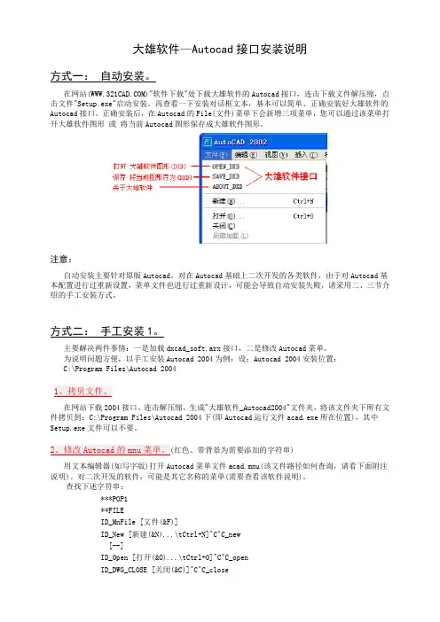
大雄软件—Autocad接口安装说明方式一:自动安装。
在网站()"软件下载"处下载大雄软件的Autocad接口,连击下载文件解压缩,点击文件"Setup.exe"启动安装。
再查看一下安装对话框文本,基本可以简单、正确安装好大雄软件的Autocad接口。
正确安装后,在Autocad的File(文件)菜单下会新增三项菜单,您可以通过该菜单打开大雄软件图形或将当前Autocad图形保存成大雄软件图形。
注意:自动安装主要针对原版Autocad。
对在Autocad基础上二次开发的各类软件,由于对Autocad基本配置进行过重新设置,菜单文件也进行过重新设计,可能会导致自动安装失败,请采用二、三节介绍的手工安装方式。
方式二:手工安装1。
主要解决两件事情:一是加载dxcad_soft.arx接口,二是修改Autocad菜单。
为说明问题方便,以手工安装Autocad 2004为例:设:Autocad 2004安装位置:C:\Program Files\Autocad 2004在网站下载2004接口、连击解压缩,生成"大雄软件_Autocad2004"文件夹,将该文件夹下所有文件拷贝到:C:\Program Files\Autocad 2004下(即Autocad运行文件acad.exe所在位置),其中Setup.exe文件可以不要。
红色、带背景为需要添加的字符串)用文本编辑器(如写字版)打开Autocad菜单文件acad.mnu(该文件路径如何查询,请看下面附注说明)。
对二次开发的软件,可能是其它名称的菜单(需要查看该软件说明)。
查找下述字符串:***POP1**FILEID_MnFile [文件(&F)]ID_New [新建(&N)...\tCtrl+N]^C^C_new[--]ID_Open [打开(&O)...\tCtrl+O]^C^C_openID_DWG_CLOSE [关闭(&C)]^C^C_close在ID_MnFile行下添加大雄软件菜单接口如下:***POP1**FILEID_MnFile [文件(&F)]ID_New [新建(&N)...\tCtrl+N]^C^C_new[--]ID_Open [打开(&O)...\tCtrl+O]^C^C_openID_DWG_CLOSE [关闭(&C)]^C^C_close附注说明:与版本有关问题。
施耐德自动化产品技术问答2006-11-11 02:57223,问:我用的PLC是PC-E984-258, 但当配置了AS-BDEP217并下载后启动PLC 时, 出现错误, 错误代码为4000, PLC 无法运行, 如何解决?当使用PC-A984-1xx, PC-E984-24x与PC-E984-25x系列的PLC时, 对某些A120I/O模块需要下载loadables, 具体说明如下:1. 要支持DEP211,DEP214,DEP215,DEP217与DAP217,需下载Dsc1.dat文件2. 要支持ADU214, 需下载Adu214.dat文件3. 要支持ADU216, 需下载Adu216.dat文件出现上面现象的原因就是没有下载支持DEP217的Dsc1.dat文件, 只要下载该文件, 以上故障即可排除..224,问:如何将ProWorx软件授权从一台PC机移到另一台PC机里?1. 将 ProWorx 软件安装到目标PC机中2. 点击”help”→”product authorization”→”software keys”, 然后记下界面右上角的”sitecode number”3. 返回源PC机, 点击”help”→”product authorization”→”software keys”→”move”→”next”4. 输入目标PC机中的”site code number”, 点击”next”, 并确认5. 插入空白软盘, 点击”next”→”finish”→”ok”6. 返回目的PC机, 点击”add”→”authorize by disk”→”next”7. 插入授权软盘, 点击”next”→”finish”→”ok”, 授权移机完成225,问:Premium,Micro通过TSXFPP10作为FIPIO agent时,如何与FIPIO主站进行数据交换?FIPIO agent与FIPIO主站之间通过共享变量的方式,进行数据交换。
1 IntroductionThe MPC56xx 32-bit microcontroller family built on Power Architecture ® technology provides a mechanism by which the e200 core implements interrupts and exceptions. Thisapplication note describes a method for decoding the length of VLE instructions, one which is used to correctly increment the returning address of the exception.2 OverviewIn this application note, core exceptions are split into two types:•Exceptions for which the address located in the SRR0 is increased automatically.•Exceptions for which the address located in the SRR0has to be increased manually based on the length of the instruction that caused the exception.This information is located in the IVORx interrupt chapter in the related e200 Core Reference Manual .Table 1 highlights IVORx exceptions that require manual incrementing of the return address in the SRR0 register for thee200z7 core. For further information, refer to the "DebugApplication NoteRev. 1, 3/2013VLE 16-bit and 32-bit Instruction Length Decode Algorithmby:Pavel Bohacik© 2013 Freescale Semiconductor, Inc.Contents1Introduction................................................................12Overview....................................................................13Machine check interrupt (IVOR1exception) example...................................................24Book E or VLE instruction decoding (25)Decoding 16-bit or 32-bit VLEinstructions................................................................35.1Decoding the condition in C...........................45.2Decoding the condition inassembly.........................................................56Conclusion.. (57)References (5)Machine check interrupt (IVOR1 exception) exampleInterrupt—Register Settings" table in the Interrupts and Exceptions chapter of document number e200z760RM, e200z760n3 Power Architecture Core Reference Manual.3Machine check interrupt (IVOR1 exception) exampleWhen an IVOR1 exception occurs (due to memory protection, for example), the e200 core sets Machine Check Save/Restore Register 0 (MCSRR0) to the address of the instruction that was executed or about to be executed when the machine check condition occurred. If a recoverable machine check exception occurred, you should update MCSSR0 appropriately in the IVOR1 handler epilog based on all recommendations mentioned in AN2865, Qorivva Simple Cookbook available at .Freescale e200 cores allow you to use both variable length encoding (VLE) 16-bit and 32-bit instructions and Book E 32-bit instructions. (Book E is not supported by the e200z0 core, however.) When a machine check interrupt occurs, MCSRR0 contains the address of the instruction that was executed when the machine check occurred. To avoid a recurrence of the machine check interrupt, you should properly increment the instruction address in MCSSR0. The increment of the instruction address depends on the type of instruction interrupted by the machine check interrupt. An increment of 4 bytes is required for Book E instructions and VLE 32-bit instructions; an increment of 2 bytes is required for VLE 16-bit instructions.4Book E or VLE instruction decodingMore powerful types of e200 cores, like the e200z7, allow a mixed execution of VLE and Book E instructions. For this reason, Book E instruction detection is required when a machine check interrupt occurs.There are several ways to determine whether a Book E or a VLE instruction was used.1.Check Instruction Register Status Bit 8 in the Control State Register (CTL[IRSTAT8]) to determine the Power ISA VLE status for the Instruction Register (IR). This is a debug register, so it is not accessible by the main core. See e200z760RM, e200z760n3 Power Architecture Core Reference Manual for further details.2.Check the Power ISA VLE bit in the Memory Management Unit's MMU Assist Register 2 to determine the type of page. Your IVORx epilog should read all valid MMU table entries (MAS1[VALID]) and compare whether the returning address located in Machine Status Save/Restore Register 0 (SRR0) fits one of MMU entries.e a global variable. To simplify the procedure with the MMU, which may be undesired because it takes a significant amount of time, you can use a global array that lists memory ranges of VLE or Book E pages and is filled during the definition of MMU entries. Your IVORx epilog then reads SRR0 and determines whether a VLE or Book E instruction was executed based on global array values.5Decoding 16-bit or 32-bit VLE instructionsWhen a VLE instruction has been successfully decoded, the interrupt handler epilog should detect whether a 16-bit or 32-bit VLE instruction has been interrupted. Depending on the type of e200 core, different 32-bit instructions are available. See VLEPEM, Variable-Length Encoding (VLE) Programming Environments Manual , for the "VLE Instruction Set Sorted by Opcode" table, which contains both 32-bit and 16-bit instructions. After detailed investigation, the difference in opcodebetween all types of 16-bit and 32-bit VLE instructions is easily visible. Table 2, which lists a range of 16-bit and 32-bit VLE instructions, is based on the table from VLEPEM.Opcode size is determined by the first 4 bits (instruction bus[0:3]). 16-bit operations use encoding 0b0xx0 and 0b1xxx, with the exception of 0b1111, which are reserved operations (32-bit). 32-bit operations use 0b0xx1. As highlighted in thefollowing table, 32-bit instructions contain values 1, 3, 5, and 7 in the most significant byte position of this opcode. 16-bit VLE instruction contains values 0, 2, 4, 6, 8, 9, 0xA, 0xB, 0xC, 0xD, and 0xE in the most significant byte position of this opcode.Decoding 16-bit or 32-bit VLE instructions5.1Decoding the condition in Cif(VLE_INSTRUCTION){if((instruction & 0x9000) == 0x1000) {// first 4 bits have a value of 1,3,5,7return address +=4; //instruction was 32-bit } else {// first 4 bits have a value of 0,2,4,6,8,9,A,B,C,D,E (and F, but F is reserved) return address +=2; //instruction was 16-bit }}5.2Decoding the condition in assemblymfspr r5,570 # MCSRR0 -> r5se_lhz r4,0(r5) # determine opcode @ MCSRR0 e_andi. r3,r4,0x9000e_cmpli 0x0,r3,0x1000 # check bit 31,28 onlye_bne __machine_check_adjust_for_16bit_opcode se_addi r5,2 # 0xx1 => 32 bit __machine_check_adjust_for_16bit_opcode:se_addi r5,2 # all others just 16 bit long mtspr 570,r5 # save adjusted return address6ConclusionThis application note describes how to correctly increment the returning address for IVORx exceptions, which do notautomatically increase it. Incrementing the returning address is required only for instructions that would cause this exception continuously, causing software to get stuck. You should always correctly handle the root cause of the IVORx exception before incrementing the returning address.7ReferencesHow to Reach Us:Home Page:Web Support:/supportUSA/Europe or Locations Not Listed:Freescale SemiconductorTechnical Information Center, EL5162100 East Elliot Road Tempe, Arizona 85284+1-800-521-6274 or +/supportEurope, Middle East, and Africa:Freescale Halbleiter Deutschland GmbH Technical Information Center Schatzbogen 781829 Muenchen, Germany +44 1296 380 456 (English)+46 8 52200080 (English)+49 89 92103 559 (German)+33 1 69 35 48 48 (French)/supportJapan:Freescale Semiconductor Japan Ltd.Headquarters ARCO Tower 15F1-8-1, Shimo-Meguro, Meguro-ku,Tokyo 153-0064Japan0120 191014 or +81 3 5437 9125***************************Asia/Pacific:Freescale Semiconductor China Ltd.Exchange Building 23F No. 118 Jianguo Road Chaoyang District Beijing 100022China+86 10 5879 8000**************************Document Number: AN4648Rev. 1, 3/2013Information in this document is provided solely to enable system and softwareimplementers to use Freescale Semiconductors products. There are no express or implied copyright licenses granted hereunder to design or fabricate any integrated circuits or integrated circuits based on the information in this document.Freescale Semiconductor reserves the right to make changes without further notice to any products herein. Freescale Semiconductor makes no warranty, representation, orguarantee regarding the suitability of its products for any particular purpose, nor does Freescale Semiconductor assume any liability arising out of the application or use of any product or circuit, and specifically disclaims any liability, including without limitation consequential or incidental damages. "Typical" parameters that may be provided in Freescale Semiconductor data sheets and/or specifications can and do vary in different applications and actual performance may vary over time. All operating parameters,including "Typicals", must be validated for each customer application by customer's technical experts. Freescale Semiconductor does not convey any license under its patent rights nor the rights of others. Freescale Semiconductor products are not designed,intended, or authorized for use as components in systems intended for surgical implant into the body, or other applications intended to support or sustain life, or for any other application in which failure of the Freescale Semiconductor product could create a situation where personal injury or death may occur. Should Buyer purchase or useFreescale Semiconductor products for any such unintended or unauthorized application,Buyer shall indemnify Freescale Semiconductor and its officers, employees, subsidiaries,affiliates, and distributors harmless against all claims, costs, damages, and expenses, and reasonable attorney fees arising out of, directly or indirectly, any claim of personal injury or death associated with such unintended or unauthorized use, even if such claims alleges that Freescale Semiconductor was negligent regarding the design or manufacture of the part.RoHS-compliant and/or Pb-free versions of Freescale products have the functionality and electrical characteristics as their non-RoHS-complaint and/or non-Pb-free counterparts.For further information, see or contact your Freescale sales representative.For information on Freescale's Environmental Products program, go to /epp.Freescale™ and the Freescale logo are trademarks of Freescale Semiconductor, Inc.All other product or service names are the property of their respective owners.© 2013 Freescale Semiconductor, Inc.。

SmartFusion2, IGLOO2, and RTG4Hard Multiplier ConfigurationSmartFusion2, IGLOO2, and RTG4 Hard Multiplier Configuration Table of ContentsIntroduction . . . . . . . . . . . . . . . . . . . . . . . . . . . . . . . . . . . . . . . . . . . . . . . . . . . . . . . . . . . . . . . . . . . . . . 3 Key Features . . . . . . . . . . . . . . . . . . . . . . . . . . . . . . . . . . . . . . . . . . . . . . . . . . . . . . . . . . . . . . . . . . . . . . . . . . . . . . 31SmartDesign. . . . . . . . . . . . . . . . . . . . . . . . . . . . . . . . . . . . . . . . . . . . . . . . . . . . . . . . . . . . . . . . . . . . . . 42Core Parameters . . . . . . . . . . . . . . . . . . . . . . . . . . . . . . . . . . . . . . . . . . . . . . . . . . . . . . . . . . . . . . . . . . 63Port Description . . . . . . . . . . . . . . . . . . . . . . . . . . . . . . . . . . . . . . . . . . . . . . . . . . . . . . . . . . . . . . . . . . . 8A Product Support. . . . . . . . . . . . . . . . . . . . . . . . . . . . . . . . . . . . . . . . . . . . . . . . . . . . . . . . . . . . . . . . . . 11Customer Service . . . . . . . . . . . . . . . . . . . . . . . . . . . . . . . . . . . . . . . . . . . . . . . . . . . . . . . . . . . . . . . . . . . . . . . . . 11 Customer Technical Support Center . . . . . . . . . . . . . . . . . . . . . . . . . . . . . . . . . . . . . . . . . . . . . . . . . . . . . . . . . . . 11 Technical Support . . . . . . . . . . . . . . . . . . . . . . . . . . . . . . . . . . . . . . . . . . . . . . . . . . . . . . . . . . . . . . . . . . . . . . . . . 11 Website . . . . . . . . . . . . . . . . . . . . . . . . . . . . . . . . . . . . . . . . . . . . . . . . . . . . . . . . . . . . . . . . . . . . . . . . . . . . . . . . . 11 Contacting the Customer Technical Support Center . . . . . . . . . . . . . . . . . . . . . . . . . . . . . . . . . . . . . . . . . . . . . . . 11 ITAR Technical Support . . . . . . . . . . . . . . . . . . . . . . . . . . . . . . . . . . . . . . . . . . . . . . . . . . . . . . . . . . . . . . . . . . . . . 12IntroductionThe Hard Multiplier for SmartFusion2, IGLOO2, and RTG4 supports two's complement normal (Figure 1) and dot product (Figure 2) multiplication.Key FeaturesThe Hard Multiplier supports two operating modes: Normal and Dot Product.•A structural netlist is generated in either Verilog or VHDL.•Individual inputs and outputs can be optionally registered with:–A common rising edge clock –Independent active-low asynchronous and synchronous clear controls –Independent active-high enable controls •Additional cascade output CDOUT can be enabled. This is the sign-extended 44 bit copy of output P .• Normal Mode Features:–Configurable operand widths for A0 and B0 between 2 and 18.–Optional assignment of operand A0 to an 18 bit two's complement constant.•Dot Product Mode Features:–Configurable operand widths for A0, B0, A1, B1 between 2 and 9.–Optional assignment of operand A0 and A1 to a 9 bit two's complement constant. Figure 1 • Normal MultiplierFigure 2 •Dot Product Multiplier1 – SmartDesignThe Hard Multiplier for SmartFusion2, IGLOO2, and RTG4 is available for download from the Libero®SoC IP Catalog via the web repository. Once listed in the Catalog you can double-click the macro toconfigure it in SmartDesign. For information on using SmartDesign to configure, connect, and generatecores, see the Libero SoC online help.Figure1-1 • Hard Multiplier Configuration Options - Normal ModeAfter configuring and generating the macro instance, you can simulate basic functionality. The macro canthen be instantiated as a component of a larger design.Figure 1-2 •Hard Multiplier Configuration Options - Dot Product Mode2 – Core ParametersTable2-1 lists the Normal mode Hard Multiplier settings; Table2-2 lists the Dot Product mode settings. Table2-1 • Hard Multiplier Normal Mode Configuration DescriptionName Valid Range DescriptionInput Port A0Use Constant Sets input port A0 to constantConstant Value (Hex)-217 to (217 - 1)Two's complement value of A0, if A0 is constant. Values shorter than18 bits are padded with zeros. Negative values must be a full 18 bitswide. For example, 0x1FFFF means +131071 (217 - 1), while 0x3FFFFmeans -1Width 2 to 18Width of input port A0; if shorter than 18 bits it is sign-extended. Forexample, if the width is 8, a value of 0x7F means +127 and a value of0xFF means -1Register Port Registers input port A0 (if A0 is not constant)Input Port B0Width 2 to 18Width of input port B0; if shorter than 18 bits it is sign-extended. Forexample, if the width is 8, a value of 0x7F means +127 and a value of0xFF means -1.Register Port Registers input port B0Output Port PRegister Port Registers output port P and CDOUTTable2-2 • Hard Multiplier Dot Product Mode Configuration DescriptionName Valid Range DescriptionInput Port A0Use Constant Sets input port A0 to constantConstant Value (Hex)-28 to (28 - 1)Two's complement value of A0, if A0 is constant. Values shorter than 9bits are padded with zeros. Negative values must be a full 9 bits wide.For example, 0xFF means +255 (28 - 1), while 0x1FF means -1Width 2 to 9Width of input port A0; if shorter than 9 bits it is sign-extended. Forexample, if the width is 8, a value of 0x7F means +127 and a value of0xFF means -1.Register Port Registers input port A0 (if A0 is not constant)Input Port A1Use Constant Sets input port A1 to constantTable2-2 • Hard Multiplier Dot Product Mode Configuration DescriptionName Valid Range DescriptionConstant Value (Hex)-28 to (28 - 1)Two's complement value of A1, if A1 is constant. Values shorter than 9bits are padded with zeros. Negative values must be a full 9 bits wide.For example, 0xFF means +255 (28 - 1), while 0x1FF means -1Width 2 to 9Width of input port A1; if shorter than 9 bits it is sign-extended. Forexample, if the width is 8, a value of 0x7F means +127 and a value of0xFF means -1.Register Port Registers input port A1 (if A1 is not constant).Input Port B0Width 2 to 9Width of input port B0; if shorter than 9 bits it is sign-extended. Forexample, if the width is 8, a value of 0x7F means +127 and a value of0xFF means -1.Register Port Registers input port B0Input Port B1Width 2 to 9Width of input port B1; if shorter than 9 bits it is sign-extended. Forexample, if the width is 8, a value of 0x7F means +127 and a value of0xFF means -1.Register Port Registers input port B1Output Port PRegister Port Registers output port P and CDOUT3 – Port DescriptionThe figures below display the Hard Multiplier input and output ports for Normal mode (Figure3-1) andDot Product mode (Figure3-2). The ports shown are a superset of all possible ports. Only a subset of theports is used in any given Hard Multiplier configuration.Figure3-1 • Hard Multiplier Ports, Normal ModeFigure3-2 • Hard Multiplier Ports, Dot Product ModeTable3-1 lists the Hard Multiplier port signals for Normal mode.Table3-1 • Hard Multiplier Ports - Normal ModeSignal Direction DescriptionA0Input Input data A0, 2 - 18 bits wideB0 Input Input data B0, 2 - 18 bits wideCLK Input Input clock for A0, B0, P and CDOUT registersA0_ACLR_N Input Asynchronous reset for data A0 registersA0_SCLR_N Input Synchronous reset for data A0 registersA0_EN Input Enable for data A0 registersB0_ACLR_N Input Asynchronous reset for data B0 registersB0_SCLR_N Input Synchronous reset for data B0 registersB0_EN Input Enable for data B0 registersP_ACLR_N Input Asynchronous reset for result P and CDOUT registers P_SCLR_N Input Synchronous reset for result P and CDOUT registers P_EN Input Enable for result P and CDOUT registersP Output Result data: P = A0 * B0CDOUT OutputCascade Cascade output of result P. CDOUT is a copy of P, sign- extended to 44 bits. The entire bus must either be dangling or drive an entire CDIN of another MATH block in normal mode.Table3-2 lists the Hard Multiplier port signals for Dot Product mode. Table3-2 • Hard Multiplier Ports - Dot Product ModeSignal Direction DescriptionA0Input Input data A0, 2 - 9 bits wideA1Input Input data A1, 2 - 9 bits wideB0Input Input data B0, 2 - 9 bits wideB1Input Input data B1, 2 - 9 bits wideCLK Input Input clock for A0, A1, B0, B1, P and CDOUT registers A0_ACLR_N Input Asynchronous reset for data A0 registersA0_SCLR_N Input Synchronous reset for data A0 registersA0_EN Input Enable for data A0 registersB0_ACLR_N Input Asynchronous reset for data B0 registersB0_SCLR_N Input Synchronous reset for data B0 registersB0_EN Input Enable for data B0 registersA1_ACLR_N Input Asynchronous reset for data A1 registersA1_SCLR_N Input Synchronous reset for data A1 registersA1_EN Input Enable for data A1 registersB1_ACLR_N Input Asynchronous reset for data B1 registersB1_SCLR_N Input Synchronous reset for data B1 registersB1_EN Input Enable for data B1 registersP_ACLR_N Input Asynchronous reset for result P and CDOUT registers P_SCLR_N Input Synchronous reset for result P and CDOUT registers P_EN Input Enable for result P and CDOUT registersP Output Result data: P = (A0 * B0) + (A1 * B1)CDOUT OutputCascade Cascade output of result P. CDOUT is a copy of P, sign- extended. The entire bus must either be dangling or drive an entire CDIN of another MATH block in dot product mode.A – Product SupportMicrosemi SoC Products Group backs its products with various support services, including CustomerService, Customer Technical Support Center, a website, electronic mail, and worldwide sales offices.This appendix contains information about contacting Microsemi SoC Products Group and using thesesupport services.Customer ServiceContact Customer Service for non-technical product support, such as product pricing, product upgrades,update information, order status, and authorization.From North America, call 800.262.1060From the rest of the world, call 650.318.4460Fax, from anywhere in the world, 408.643.6913Customer Technical Support CenterMicrosemi SoC Products Group staffs its Customer Technical Support Center with highly skilledengineers who can help answer your hardware, software, and design questions about Microsemi SoCProducts. The Customer Technical Support Center spends a great deal of time creating applicationnotes, answers to common design cycle questions, documentation of known issues, and various FAQs.So, before you contact us, please visit our online resources. It is very likely we have already answeredyour questions.Technical SupportVisit the Customer Support website (/soc/support/search/default.aspx) for moreinformation and support. Many answers available on the searchable web resource include diagrams,illustrations, and links to other resources on the website.WebsiteYou can browse a variety of technical and non-technical information on the SoC home page, at/soc.Contacting the Customer Technical Support CenterHighly skilled engineers staff the Technical Support Center. The Technical Support Center can becontacted by email or through the Microsemi SoC Products Group website.EmailYou can communicate your technical questions to our email address and receive answers back by email,fax, or phone. Also, if you have design problems, you can email your design files to receive assistance.We constantly monitor the email account throughout the day. When sending your request to us, pleasebe sure to include your full name, company name, and your contact information for efficient processing ofyour request.The technical support email address is **********************.115-02-00366-1/04.15Microsemi makes no warranty, representation, or guarantee regarding the information contained herein or the suitability of its products and services for any particular purpose, nor does Microsemi assume any liability whatsoever arising out of the application or use of any product or circuit. The products sold hereunder and any other products sold by Microsemi have been subject to limited testing and should not be used in conjunction with mission-critical equipment or applications. Any performance specifications are believed to be reliable but are not verified, and Buyer must conduct and complete all performance and other testing of the products, alone and together with, or installed in, any end-products. Buyer shall not rely on any data and performance specifications or parameters provided by Microsemi. It is the Buyer's responsibility to independently determine suitability of any products and to test and verify the same. The information provided by Microsemi hereunder is provided "as is, where is" and with all faults, and the entire risk associated with such information is entirely with the Buyer. Microsemi does not grant, explicitly or implicitly, to any party any patent rights, licenses, or any other IP rights, whether with regard to such information itself or anything described by such information. Information provided in this document is proprietary to Microsemi, and Microsemi reserves the right to make any changes to the information in this document or to any products and services at any time without notice.Microsemi Corporation (Nasdaq: MSCC) offers a comprehensive portfolio of semiconductor and system solutions for communications, defense and security, aerospace, and industrial markets. Products include high-performance and radiation-hardened analog mixed-signal integrated circuits, FPGAs, SoCs, and ASICs; power management products; timing and synchronization devices and precise time solutions, setting the world's standard for time; voice processing devices; RF solutions; discrete components; security technologies and scalable anti-tamper products; Power-over-Ethernet ICs and midspans; as well as custom design capabilities and services. Microsemi is headquartered in Aliso Viejo, Calif. and has approximately 3,400 employees globally. Learn more at .Microsemi Corporate HeadquartersOne Enterprise, Aliso Viejo,CA 92656 USAWithin the USA: +1 (800) 713-4113Outside the USA: +1 (949) 380-6100Sales: +1 (949) 380-6136Fax: +1 (949) 215-4996E-mail:***************************©2015 Microsemi Corporation. All rightsreserved. Microsemi and the Microsemilogo are trademarks of MicrosemiCorporation. All other trademarks andservice marks are the property of theirrespective owners.My CasesMicrosemi SoC Products Group customers may submit and track technical cases online by going to My Cases .Outside the U.S.Customers needing assistance outside the US time zones can either contact technical support via email (**********************) or contact a local sales office. Sales office listings can be found at /soc/company/contact/default.aspx.ITAR Technical SupportFor technical support on RH and RT FPGAs that are regulated by International Traffic in Arms Regulations (ITAR), contact us via ***************************. Alternatively, within My Cases , select Yes in the ITAR drop-down list. For a complete list of ITAR-regulated Microsemi FPGAs, visit the I TAR web page.。
安装与建立Qt 桌面运行环境一、实验目的1. 了解在Linux 下安装Qt 以及Qt/Embedded 的基本步骤;2. 学会在Qt/E 平台下使用Virtual framebuffer 显示程序结果;二、实验内容1. 在Linux 下编译和使用Qt/E 平台;2. 在Qt/E 平台下编译和运行一个程序使用Virtual framebuffer 显示运行结果;三所需工具tmake-1.13.tar.gz qt-embedded-2.3.10-free.tar.gz qt-x11-2.3.2 .tar.gz cross-arm四、实验步骤在Trolltech公司的网站上可以下载该公司所提供的Qt/Embedded 的免费版本,在/arm2410s/gui/Qt/src 下。
在做实验前把本次实验用到的三个文件拷贝到/root/2410sQt 目录下。
[root@binnary root]#cd /root/[root@ binnary root]#mkdir 2410sQt[root@ binnary root]#cd /arm2410s/gui/Qt/src[root@ binnary src]#cp -arf tmake-1.13.tar.gz qt-embedded-2.3.10-free.tar.gz qt-x11-2.3.2.tar.gz/root/2410sQt安装编译器arm-linux-gcc将该文件中的PATH 变量改为PATH[root@ binnary tools]# source /root/.bash_profile如果安装正确的话,在任意路径下输入ar 后按Tab 键即可列出编译器文件。
Qt/Embedded 平台的搭建需要以下几步:第一步,解压安装包并设置环境变量1.安装Tmakecd ~/2410sQttar –xzf tmake-1.13.tar.gzexport TMAKEDIR=$PWD/tmake-1.132.安装Qt 2.3.2cd ~/2410sQttar –xzf qt-x11-2.3.2.tar.gzexport QT2DIR=$PWD/qt-2.3.23.安装Qt/Embeddedcd ~/2410sQttar –xzf qt-embedded-2.3.10-free.tar.gzexport QTEDIR=$PWD/qt-2.3.10环境变量的设置是非常重要的,它关系到能否正确的安装及编译这些安装包,下面介绍一下这些环境变量:TMAKEDIR : 指向用于编译Qt/Embedded 的Tmake 工具QT2DIR : 指向qt-2.3.2 的文件夹QTEDIR : 指向qt-2.3.10 的文件夹第二步,编译Qt/Embedded。
Lab5: 终端状态检查Posture Services配置指南一、目的 (1)二、Posture Services工作流程 (1)三、实验环境 (2)实验5.1 Agent的推送与检测配置 (5)实验5.2 授权策略配置 (9)实验5.3 终端状态检查策略的配置 (12)实验5.4 测试NAC Agent的推送与终端状态检查 (15)一、目的本文介绍了思科ISE实现终端状态检查Posture Service的具体配置步骤。
这个配置步骤是以有线网络的配置场景为例,对于无线网络的应用场景,只需要在Authentication Policy 中启用Wireless_802.1x就可以了,其他配置步骤不需要改动。
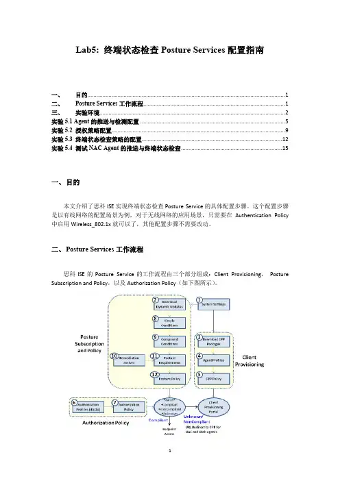
二、Posture Services工作流程思科ISE的Posture Service的工作流程由三个部分组成:Client Provisioning,Posture Subscription and Policy,以及Authorization Policy(如下图所示)。
1.Client Provisioning客户端的推送要完成终端设备的状态的评估,并确定合规检查的结果,需要推送Agent到终端设备上。
ISE的Agent程序安装后可以永久存在(NAC Agent),当每次用户登录时,会被自动加载。
Agent程序也可以临时存在(Web Agent),这是通过Web方式在用户建立新的会话时动态的下载,运行完成后再进行删除。
Agent还负责设备的修复工作,同时还为用户提供了一个AUP策略的提示。
因此,在工作流程开始的几个步骤中,包含了从思科网站上获取Agent文件,然后创建Client Provisioning策略,该策略是基于客户端的属性(如用户身份或客户端操作系统类型),确定下载到终端设备的Agent程序和配置描述文件。
2.Posture Subscription and Policy终端状态检查的判定条件与策略定义一系列的强制判断条件,用于判定终端设备是否被视为“合规”,包括文件,注册表,进程,Windows补丁,以及AS/AV的检查规则。
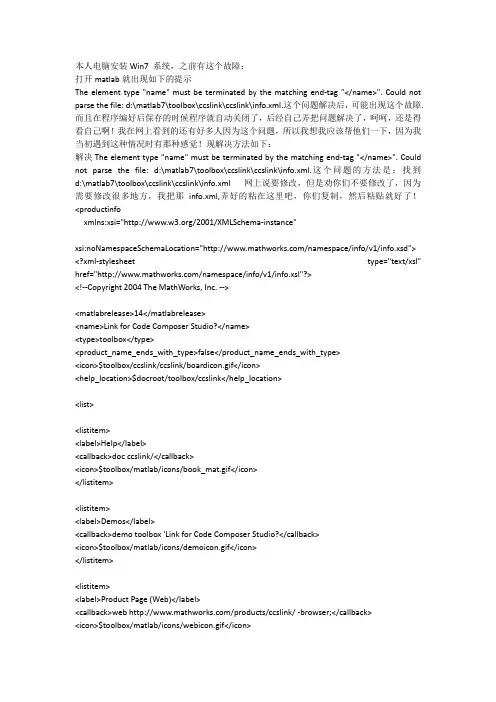
本人电脑安装Win7 系统,之前有这个故障:打开matlab就出现如下的提示The element type "name" must be terminated by the matching end-tag "</name>". Could not parse the file: d:\matlab7\toolbox\ccslink\ccslink\info.xml.这个问题解决后,可能出现这个故障.而且在程序编好后保存的时候程序就自动关闭了,后经自己弄把问题解决了,呵呵,还是得看自己啊!我在网上看到的还有好多人因为这个问题,所以我想我应该帮他们一下,因为我当初遇到这种情况时有那种感觉!现解决方法如下:解决The element type "name" must be terminated by the matching end-tag "</name>". Could not parse the file: d:\matlab7\toolbox\ccslink\ccslink\info.xml.这个问题的方法是:找到d:\matlab7\toolbox\ccslink\ccslink\info.xml 网上说要修改,但是劝你们不要修改了,因为需要修改很多地方,我把那info.xml,弄好的粘在这里吧,你们复制,然后粘贴就好了!<productinfoxmlns:xsi="/2001/XMLSchema-instance"xsi:noNamespaceSchemaLocation="/namespace/info/v1/info.xsd"> <?xml-stylesheet type="text/xsl" href="/namespace/info/v1/info.xsl"?><!--Copyright 2004 The MathWorks, Inc. --><matlabrelease>14</matlabrelease><name>Link for Code Composer Studio?</name><type>toolbox</type><product_name_ends_with_type>false</product_name_ends_with_type><icon>$toolbox/ccslink/ccslink/boardicon.gif</icon><help_location>$docroot/toolbox/ccslink</help_location><list><listitem><label>Help</label><callback>doc ccslink/</callback><icon>$toolbox/matlab/icons/book_mat.gif</icon></listitem><listitem><label>Demos</label><callback>demo toolbox 'Link for Code Composer Studio?</callback><icon>$toolbox/matlab/icons/demoicon.gif</icon></listitem><listitem><label>Product Page (Web)</label><callback>web /products/ccslink/ -browser;</callback><icon>$toolbox/matlab/icons/webicon.gif</icon></listitem></list></productinfo>有些Win7 里(info.xml)这个文件是后缀名不是.xml,请务必改过来,然后再复制粘贴保存!解决前面那个问题,另一个故障就是:编好程序后,想保存运行,但是一保存,Matlab 软件就自动关闭了,如:遇到这个问题,是因为我在网上看到如下图所示:解决方法是:将兼容模式运行这个程序改为Vista 如下图所示:然后点击应用、确定就OK了,然后再打开Matlab 7 就行了!下面是我在网上看到的其它解决方法,但行不行得通还得自己去实验了,不过我遇到的那种情况在我这里肯定是能够搞定的!安装问题集中解决故障一:安装MATLAB时总是出现下面的显示: The installer cannot read the mwinstall.dll file, This is probably due to a CD reader which can only read files with an eight.three naming convention.Please see the technical support page at / for assistance.解决方法:绝大多数情况是因为matlab安装程序放在了一个中文目录下面了,只要把路径改成英文或数字即可。

Copyright and Confidentiality StatementAny information contained in this document, whether it is related to Inspur or its partners, including but not limited to functional description, policies, processes, decisions, employee information, agent and customer information, and all financial data, shall be kept in strict confidence.Copyright© Inspur Group Limited 2012文档信息文档修改记录版权及保密性声明本文档中包含的所有信息,无论涉及到浪潮还是其合作伙伴(包括但不限于功能描述、政策、流程、决定、雇员信息、代理及客户信息以及所有的财务信息),都必须绝对保密。
此报告为浪潮信息客户服务部为XX用户提供,本文件中出现的任何文字叙述、文档格式、插图、照片、方法、过程等内容,除另有特别注明,版权均属浪潮信息所有,受到有关产权及版权法保护。
任何单位和个人未经浪潮信息的书面授权许可,不得复制或引用本文件的任何片断,无论通过电子形式或非电子形式。
浪潮集团版权所有© 2012目录1.用户信息........................................... 错误!未定义书签。
.用户信息.................................................. 错误!未定义书签。
2.设备信息........................................... 错误!未定义书签。
.交换机信息................................................ 错误!未定义书签。
中铁十一局二公司宿淮铁路指挥部测量室CASIO fx-5800测量应用程序编著者:刘杰赵宝注;本程序只供参考如果出现由程序引起的施工事故编著者一律不予承担法律责任。
一直线中边桩坐标程序(ZX)“ZH--X”?A;“ZH--Y”?B;“Z H”?C;“WH”?D;“QIEXIAN—ZH”?O LbI 0;D-C→SA+S×coc(O)→FB+S×sin(O)→G“L-1 R-0”?H;“S”?JIf H=1;Then O-90→K;Eles O+90→K;IfendF+J×cos(K)→XG+J×sin(K)→Y“X=”;X⊿“Y=”;Y⊿“WH”?D;Goto 0注释;ZH—X输入直缓点X坐标,ZH—Y输入直缓点Y坐标,ZH输入缓直点里程,WH输入待求点里程,QIEXIAN—ZH输入直缓点切线方位角。
二曲线中边桩坐标程序(QX)70→DimZ“ZH”?A; “L0”?L; “R”?R; “ao”?E; “ZH-X”?C; “ZH-Y”?D “QIEXIAN”?F; “WISE”?GIf G=0;Then F+E→Z[38];Else F+E→Z[38];Ifend]33[6479.28]32[238424]31[240234223Z R L Z R L R L Z R L L →÷⨯→÷÷-÷÷→÷÷-÷(R+Z[32]) ×tan(E/2)+Z[31] →Z[35](E-2×Z[32]) ×π÷180×R+2×L →Z[34]A+Z[34] →Z[36]C+Z[35] ×cos(F) →Z[39]D+Z[35]×sin(F )→Z[40]Z[39]+Z[35] ×cos(Z[38]) →Z[41]Z[40]+Z[35]×sin(Z[38])→Z[42]Z[38]+180→Z[43]“WH”?BZ[36]-L →Z[60]If B< Z[60];Then Prog “1”;Else Prog “2”;Ifend注释;ZH 输入直缓点里程,WH 待求点里程,L0缓和曲线长度,R=输入半径,ZH-X 直缓点的X 坐标,ZH-Y 直缓点的Y 坐标,ao 输入转角,QIEXIAN 直缓点的切线方位角,WISE 左转曲线输入1,右转曲线输入0。
毕昇编译器2.1.0用户指南文档版本01发布日期2021-12-30版权所有 © 华为技术有限公司 2021。
保留一切权利。
非经本公司书面许可,任何单位和个人不得擅自摘抄、复制本文档内容的部分或全部,并不得以任何形式传播。
商标声明和其他华为商标均为华为技术有限公司的商标。
本文档提及的其他所有商标或注册商标,由各自的所有人拥有。
注意您购买的产品、服务或特性等应受华为公司商业合同和条款的约束,本文档中描述的全部或部分产品、服务或特性可能不在您的购买或使用范围之内。
除非合同另有约定,华为公司对本文档内容不做任何明示或暗示的声明或保证。
由于产品版本升级或其他原因,本文档内容会不定期进行更新。
除非另有约定,本文档仅作为使用指导,本文档中的所有陈述、信息和建议不构成任何明示或暗示的担保。
华为技术有限公司地址:深圳市龙岗区坂田华为总部办公楼邮编:518129网址:https://客户服务邮箱:******************客户服务电话:4008302118目录1 毕昇编译器介绍 (1)2 毕昇编译器安装使用 (2)2.1 环境依赖 (2)2.2 获取毕昇编译器 (2)2.3 安装毕昇编译器 (3)2.4 使用毕昇编译器 (3)2.5 安全加固 (4)3 毕昇编译器选项说明 (5)3.1 默认选项 (5)3.2 指定数学库 (5)3.3 指定jemalloc (6)3.4 LTO优化 (6)3.5 浮点运算控制选项 (6)3.6 自定义优化选项 (8)4 Fortran语言引导语 (12)5 GDB调试 (15)5.1 约定 (15)5.2 不支持场景(按需更新) (15)5.2.1 Fortran函数入参调试信息丢失 (15)5.2.2 无法进入Fortran代码的函数内部进行单步调试 (16)5.3 通过升级gdb版本解决部分问题 (16)6 已知故障与解决方法(按需更新) (18)6.1 约定 (18)6.2 编译极复杂表达式导致栈耗尽 (18)7 兼容性说明 (20)7.1 概述 (20)7.2 Clang不支持问题 (20)7.2.1 不支持print-multi-os-directory (20)7.2.2 不支持选项-fstack-clash-protection (21)7.2.3 不支持__builtin_longjmp/__builtin_setjmp (21)7.2.4 不支持__uint128_t (21)7.2.5 不支持选项-aux-info (22)7.2.6 不支持__ builtin___snprintf_chk (22)7.2.7 不支持NEON指令 (22)7.2.8 不支持部分运行库 (23)7.2.9 不支持原子类型(atomic type)的类型转换 (23)7.3 链接问题 (23)7.3.1 指定pic、pie (24)7.3.2 给链接器参数加上-Wl (24)7.3.3 Clang不再默认传递--build-id到链接器 (25)7.3.4 系统libstdc++库版本过低导致符号未定义或运行结果错误 (25)7.4 其它类兼容问题 (25)7.4.1 Clang预处理器结果与GCC存在较大差异 (25)7.4.2 Clang不支持在使用'-o'指定输出时直接添加头文件 (26)7.4.3 不同编译器对built-in includes的实现不同 (26)7.4.4 不同编译器链接的OpenMP运行时库不同 (27)7.4.5 __builtin_prefetch 语义检查错误 (27)7.4.6 找不到符号perl_tsa_mutex_lock (28)7.4.7 Clang 宏问题 (29)7.4.8 支持的Attributes集合 (29)7.4.9 -march选项在架构扩展特性上的使用说明 (29)7.4.10 -mgeneral-regs-only选项的使用说明 (29)7.4.11 -ffixed-line-length-n选项的使用说明 (29)7.4.12 -mllvm -unroll-runtime选项的使用说明 (29)7.4.13 依赖操作系统libatomic库的使用说明 (29)7.4.14 128位浮点数学库支持说明 (30)7.5 Flang兼容性 (30)7.5.1 Fortran与C互操作,main函数双重定义 (30)7.5.2 Flang中调用getpid()等系统调用需额外声明 (30)7.5.3 Flang中将算术表达式直接作为NORM2函数的输入时需要额外选项 (30)7.5.4 Flang对多维数组的大小支持有限 (31)7.6 Intrinsic Procedures (31)7.6.1 etime is not an intrinsic function (31)7.6.2 CPU_TIME (31)7.6.3 SYSTEM_CLOCK (31)7.6.4 RTL库函数 (32)7.6.5 Neon Intrinsic (32)7.7 HPC Workload应用支持范围 (34)8 附录 (35)8.1 问题反馈 (35)8.2 修订记录 (35)1毕昇编译器介绍前言本手册提供毕昇编译器的使用方法以及构建业务场景的注意事项。
Sun Microsystems, Inc.请到以下网址提交您对本文档的意见和建议:/hwdocs/feedbackSun Blade™ X6240服务器模块安装指南文件号码 820-5249-10,修订版 A 2008 年 6 月请回收利用版权所有 © 2008 Sun Microsystems, Inc., 4150 Network Circle, Santa Clara, California 95054, U.S.A. 保留所有权利。
Sun Microsystems, Inc. 拥有本文档所述产品技术的知识产权。
需特别指出的是(但不局限于此),这些知识产权可能包含在/patents 中列出的一项或多项美国专利,以及在美国和其他国家/地区申请的一项或多项其他专利或待批专利。
本产品的某些部分可能是从 Berkeley BSD 系统衍生出来的,并获得了加利福尼亚大学的许可。
UNIX 是 X/Open Company, Ltd. 在美国和其他国家/地区独家许可的注册商标。
Sun 、Sun Microsystems 、Sun 徽标、Java 、Solaris 、Sun Blade 、 、Sun Fire 以及 Solaris 徽标是 Sun Microsystems, Inc. 在美国和其它国家/地区的商标或注册商标 。
Microsoft 是 Microsoft Corporation 或其子公司在美国和其他国家/地区的商标或注册商标。
Window 是 Microsoft Corporation 或其子公司在美国和其他国家/地区的商标或注册商标。
Adobe. 徽标是 Adobe Systems, Incorporated 的注册商标。
对任何 CPU 备件或更换件的使用仅限于对遵照美国出口法律出口的产品中的 CPU 进行修复或一对一更换。
除非经过美国政府授权,否则,严禁将 CPU 用于产品升级 。
浪潮故障诊断软件工具集用户手册文档版本:2.2发布日期:2017-3-19目录目录 (2)版本信息 (5)第一部分浪潮LINUX版日志收集工具 (6)1概述 (6)1.1 功能简介 (6)1.2 规格说明 (6)1.3 应用说明 (6)2安装与使用 (8)2.1 安装步骤 (8)2.2 使用方法 (8)3日志收集 (9)3.1 功能介绍 (9)3.2使用方法 (15)第二部分浪潮WINDOWS版日收集工具 (17)1概述 (17)1.1 功能简介 (17)1.2 规格说明 (17)1.3 应用说明 (18)2安装与使用 (19)2.1 安装步骤 (19)2.2 使用方法 (19)3日志收集 (22)3.1 功能介绍 (22)3.2 使用方法 (26)4IPMI工具 (29)4.1 功能介绍 (29)4.2 使用方法 (29)5黑盒日志解析工具 (31)5.1 功能介绍 (31)5.2 使用方法 (31)第三部分浪潮单机版压力测试工具 (32)1概述 (32)1.1 功能简介 (32)1.2 规格说明 (32)1.3 应用说明 (33)2安装与使用 (34)2.1 安装步骤 (34)3硬件信息展示 (36)3.1 功能介绍 (36)3.2 使用方法 (36)4CPU压力测试 (40)4.1 功能介绍 (40)4.2 使用方法 (40)5内存压力测试 (41)5.1 功能介绍 (41)5.2 使用方法 (41)6硬盘压力测试 (42)6.1 功能介绍 (42)6.2 使用方法 (42)7日志收集和故障诊断 (43)7.1 功能介绍 (43)7.2 使用方法 (43)8保存日志到U盘 (46)8.1 功能介绍 (46)8.2 使用方法 (46)第四部分浪潮云端故障诊断系统 (47)1概述 (47)1.1 功能简介 (47)1.2 规格说明 (47)1.3 应用说明 (48)2安装与使用 (49)2.1 安装步骤 (49)2.2 使用方法 (49)3故障分布统计 (50)3.1 功能介绍 (50)3.2 使用方法 (50)4批量上传日志 (52)4.1 功能介绍 (52)4.2 使用方法 (52)5故障诊断 (53)5.1 功能介绍 (53)5.2 使用方法 (55)6诊断结果导出 (57)6.1 功能介绍 (57)6.2 使用方法 (57)7普通用户修改密码 (58)7.1 功能介绍 (58)7.2 使用方法 (58)8用户管理 (59)8.1 功能介绍 (59)9故障规则录入 (60)9.1 功能介绍 (60)9.2 使用方法 (60)附-LIVEUSB制作(WINDOWS) (61)版本信息版本完成日期变更记录变更人1.0 2016.6.18 新建王兴隆1.1 2016.7.11 修改操作王兴隆2.0 2016.11.19 完善诊断工具王兴隆2.1 2017.3.16 整合浪潮诊断软件工具集用户手册,包括Linux日志搜集工具、Windows日志收集工具、单机压力测试工具、云端故障诊断系统王兴隆2.2 2017.3.21 增加可诊断故障列表王兴隆第一部分浪潮Linux版日志收集工具1概述1.1 功能简介Linux版日志收集工具面向客服、测试、工程人员,工具运行在Linux系统下收集服务器故障日志。
Installation, Maintenance& Parts ManualTable of ContentsWarnings – General Safety2. . . . . . . . . . . . . . . . . . . . Introduction2 . . . . . . . . . . . . . . . . . . . . . . . . . . . . . . . .Installation3 . . . . . . . . . . . . . . . . . . . . . . . . . . . . . . . . . RequiredTools3. . . . . . . . . . . . . . . . . . . . . . . . . . . . Mounting When Ordered With Conveyor3. . . . . . . Mounting When Ordered Without Conveyor4. . . . Service Parts 5. . . . . . . . . . . . . . . . . . . . . . . . . . . . . . . Return Policy6. . . . . . . . . . . . . . . . . . . . . . . . . . . . . . .851-468 Rev. BEnd Stop for 2200 Series Conveyors: Installation, Maintenance & Parts Manual851-468 Rev. B2Dorner Mfg. Corp.IntroductionIMPORTANT: Some illustrations may showguards removed. DO NOT operate equipment with-out guards.Upon receipt of shipment:D Compare shipment with packing slip. Contact factory regarding discrepancies.D Inspect packages for shipping damage. Contact carrier regarding damage.D Accessories may be shipped loose. See accessory in-structions for installation.Dorner 2200 Series conveyors are covered by Patent No. 5,174,435, 5,131,529 and corresponding patents and patent applications in other countries.Dorner ’s Limited Warranty applies.Dorner reserves the right to make changes at any time without notice or obligation.Warnings – General SafetyEnd Stop for 2200 Series Conveyors: Installation, Maintenance & Parts ManualDorner Mfg. Corp.3851-468 Rev. BRequired ToolsD Hex key wrenches:2.5 mm, 4 mm, 5 mm D Torque wrenchMounting When Ordered With Conveyor1.Gather components (Figure 1)Figure 1BACA End StopB Spacer (2x)CM5 x 45 Socket Head Screw (2x)Installation Component List2.Insert spacer (B of Figure 2) in both ends of endstop (A).Figure 2BA3.Install end stop with spacers (A of Figure 3) on endof conveyor with M5 screws (CC). Tighten screws to 60 in-lb (7 Nm).Figure 3ACInstallationEnd Stop for 2200 Series Conveyors: Installation, Maintenance & Parts Manual851-468 Rev. B4Dorner Mfg. Corp.Mounting When Ordered Without Conveyor1.Gather components (Figure 4)Figure 4EDBACA End StopB Spacer (2.)C M5 x 45 Socket Head Screw (2x)D Headplate (LH)EHeadplate (RH)Installation Component List2.Remove conveyor end pulley. See “Pulley Remov-al ” on page 13 of “2200 Series End Drive Convey-ors ” manual, part number 851–452.3.Remove bearings from conveyor headplates and install them into new headplates (D & E of Figure 4).See “Bearing Removal and Replacement ” on page 14 of “2200 Series End Drive Conveyors ” manual,part number 851–452.4.Replace end pulley and new headplates. See “PulleyReplacement ” on page 15 of “2200 Series End Drive Conveyors ” manual, part number 851–452.5.Install conveyor belt. See belt installation section onpage 10 of “2200 Series End Drive Conveyors ”manual, part number 851–452.6.Tension the conveyor belt. See “Conveyor BeltTensioning ” on page 11 of “2200 End Drive Conveyors ” manual, part number 851–452.7.Insert spacer (B of Figure 5) in both ends of endstop (A).Figure 5BA8.Install end stop with spacers (A of Figure 6) on endof conveyor with M5 screws (C). Tighten screws to 60 in-lb (7 Nm).Figure 6ACInstallationEnd Stop for 2200 Series Conveyors: Installation, Maintenance & Parts ManualDorner Mfg. Corp.5851-468 Rev. BNOTE: For replacement parts other than those shown on this page, contact an authorized Dorner Service Center or the factory.Figure 721435Service PartsNo returns will be accepted without prior written factory authorization. When calling for authorization, please have the following information ready for the Dorner Factory representative or your local distributor: and address of customer.2.Item(s) being returned.3.Reason for return.4.Customer ’s original order number used when ordering the item(s).5.Dorner or distributor invoice number.A representative will discuss action to be taken on the Returned items and provide a Returned Goods Authorization Number to reference.There will be a 15% restocking charge on all new items returned for credit where Dorner was not at fault. These will not be accepted after 60 days from original invoice date. The restocking charge covers inspection, cleaning,disassembly, and reissuing to inventory.If a replacement is needed prior to evaluation of returned item, a purchase order must be issued. Credit (if any) is issued only after return and evaluation is complete.Dorner has representatives throughout the world. Feel free to contact Dorner for the name of your local representative. Our technical sales and service staff will gladly help with your questions on Dorner products.For a copy of Dorner ’s Limited Warranty, contact factory, distributor, service center or visit our website @851-468 Rev. BPrinted in U.S.A.1299For replacement parts, contact an authorizedDorner Service Center or the factory.Return Policy。
利用API开发串行通信程序
雷学生
【期刊名称】《金融科技时代》
【年(卷),期】2005(013)012
【摘要】本文通过对Windows环境下串行通信技术的分析,介绍了一种利用Visual Basic6.0语言开发串行通信程序的方法,实现了PC机与工控机之间的串行通信技术.
【总页数】3页(P75-77)
【作者】雷学生
【作者单位】北华大学
【正文语种】中文
【中图分类】TP3
【相关文献】
1.Delphi中利用ComPort元件开发串行通信程序 [J], 赵曙光
2.利用Visual C++6.0编制串行通信程序的实现 [J], 胡赤兵;桑瑞鹏
3.C++中利用ComPort元件开发串行通信程序 [J], 王万勇;王希军
4.在VC+ +中利用ActiveX控件开发串行通信程序 [J], 王楠
5.在VC++中利用Win32API开发串行通信程序 [J], 陈耕
因版权原因,仅展示原文概要,查看原文内容请购买。