智能SCHIEBEL中文说明书
- 格式:doc
- 大小:639.50 KB
- 文档页数:10
![奥地利西贝SCHIEBEL执行机构操作手册[1]](https://uimg.taocdn.com/0b572ad276eeaeaad1f330a9.webp)
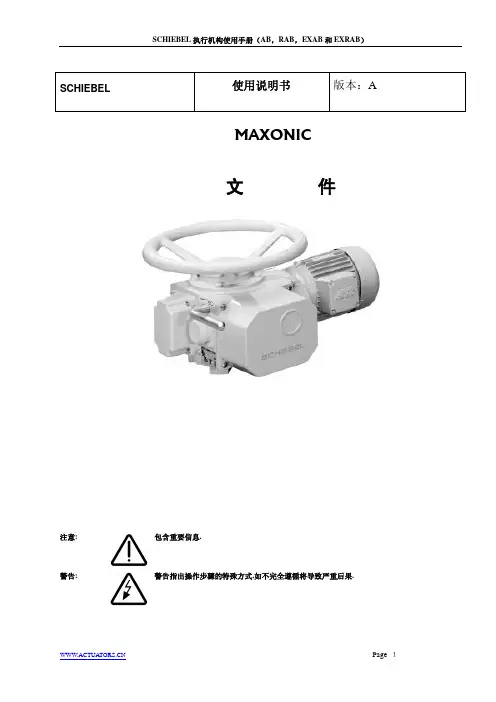

智能S C H I E B E L中文说明书(总8页)--本页仅作为文档封面,使用时请直接删除即可----内页可以根据需求调整合适字体及大小--智能SCHIEBEL调试文件智能SCHIEBEL是具有SMARTCON控制单元的智能型执行机构,它通过参数设置和内部程序控制,能有效增强控制的灵活性和舒适性,通过良好的人机界面交流,能最大限度发挥操作的简易性,它所具有的强大功能是其它执行机构所无法比拟的。
下面是对智能SCHIEBEL操作的简要介绍以及调试说明,供用户参考。
一、界面操作与LED提示灯介绍1. 界面与操作通过选择开关(红)可以选择三种不同的操作形式:OFF 停止L就地(LOCAL). 此时只有用操作开关才能操作执行机构动作.远程控制 (REMOTE). 此时执行机构的动作只接受系统来的信号,不受操作开关的手动控制.根据选择开关的位置,操作开关就能获得不同的功能:选择开关在“OFF”位置:操作开关被用来上、下翻动菜单,操作开关从中间旋向的方向,可用来观察数据记录状态(S项及H项) ,从中间旋向的方向可以观察参数菜单(P 项)在菜单里,选择开关具有对实际输入的确认和取消的功能,选择开关15度的旋转可用来确认或取消参数项里的各种输入(如果要修改参数请注意将左下角的“edit ”变为“save ”才能修改,如果要确认参数请注意将“save ”变为“edit ”).如果在菜单中想快速返主界面,请将选择开关打到L位置即可。
选择开关在“REMOTE”位置这个状态是远程控制状态, 通过操作开关只可观察不同的数据记录,不能进行参数的设定选择开关在“LOCAL”位置操作开关被用来控制执行机构,既可以将开关置于机械保持位置使执行机构做持续运动,也可以通过小幅偏转使执行机构点动,.点动时操作开关都能通过弹簧回到中间位置2. LED 指示灯名称 颜色 亮闪烁 不亮 L1 红 开 正在开启 没到开位 L2 绿 关 正在关闭 没到关位 L3 黄 转矩正常 转矩故障---------------L4 黄就绪报警故障二、 调试说明调试是在确定机械安装和电气连接正确无误后方可进行!产品在出厂之前,参数都已按基本要求设置完成,请不要随意更改。

索引1.绪论2.简介总览序列号操作模式防护等级安装位置旋转方向保护装置环境温度执行机构的交货状况标签3.包装.运输和储存简介储存长期储存4.安装说明4.1. 机械安装4.2 接线5. 启动5.1.变换执行机构到手动5.2.预先机械调节5.3.机械位置指示的调节(操作)5.4.SMARTCON的参数控制5.5.附加元件6. SMARTCON控制6.1.界面6.2.显示原理6.3.操作7. 参数7.1 参数组: 限位7.2. 参数组: 转矩7.3.参数组: 密码7.4.参数组: 位置7.5. 参数组: 数字输入7.6. 参数组: 数字输出7.7.参数组: 位置信号(选项)7.8.参数组: 步进运动7.9.参数组: 远程位置调节器(选项)7.10.参数组: PID远程位置调节器(选项)7.11.参数组: Profibus(选项)7.12.参数组: 多样性7.13.参数组: 电路板7.14.参数组: 数据记录8. 状态菜单8.1.状态8.2.历史8.3.数据记录9. 红外线连接10. 维护11.故障诊断12.保险丝13.备件14.推荐使用润滑剂主要部分润滑剂使用年限润滑剂要求15.培训16.关于机械部件的声明17.综述18.技术参数SMARTCON控制智能型执行机构操作手册(CSC0502e) 1.绪论本手册适合于具有SMARTCON控制的AB型SCHIEBEL执行机构.通过使用RISC处理器,执行机构的控制单元能够提供比我们到目前为止所知的控制更多的灵活性和舒适性.应用范围为工业阀门的控制.例如旋塞阀, 闸阀,蝶阀以及球阀.如有其他的应用,请联系我们.对于超出指定使用范围以外的使用所造成的损坏,SCHIEBEL公司不予以负责.由用户自行承担责任.必须遵守操作说明书来使用执行机构,请用户务必于使用前阅读此手册在接电操作期间不可避免的部分部件会带电压.所以操作电气系统或设备必须由熟练的电工本人来执行,或者是在电工的监督和控制下经过培训的人员来完成,他们必须遵守电工规则.务必遵守维护使用说明书,否则就不能保证执行机构安全.长久的运行.不遵守警告和注意可能会导致严重的后果.操作人员必须十分地熟悉在操作说明中所有的警告和注意恰当的运输,正确的贮藏.合理的安装.小心的试车.精心的维护,只有如此才能从根本上保证无故障的安全运行.2.简介总览图1序列号每一个执行机构都有独自的序列号,也称之为装配号.序列号是一个8位数.起始为生产年限.它被刻于执行机构的标牌(见图2)上(执行机构的标牌位于手柄的下方见图3).在SCHIEBEL公司的产品记录上将序列号作为执行机构唯一的证明(型号,尺寸,运行,选项,技术数据和检查报告)图2图3用于防爆的执行机构(依照EN 50014 标准)单独使用专有标牌(Eex,TüV-标准)图4操作模式有两种截然不同的操作模式:依照VDE0530DE 的开环控制(操作模式S2,开关型)和闭环控制(操作模式S4)。
Intrusion DetectorReference Guide2 | Bosch Security SystemsTable of ContentsIntroduction3Blue Line Series6Commercial Series8Professional Series10Classic Line12RADION wireless18Specialty Sensors20Detector Reference Guide | 3Security you can rely onWhether you are securing a home, retail store, bank, museum, commercial business or government facility, you need dependability from your systems. With decades of experience and an unwavering dedication to high-quality and high-performing products, Bosch detectors provide best-in-class false alarm immunity and catch performance while minimizing installation time and complexity. Millions of residential and commercial users rely on Bosch for superior intrusion detection.Bosch is recognized throughout the security industry as a global leader in intrusion detection expertise. We have earned this reputation by consistently providing products that meet your needs with a focus on performance, reliability, durability, and ease of installation.Bosch detectors fulfill the requirements of standards allover the world. In the state-of-the-art Bosch laboratory, we verify that our detectors pass the most stringent requirements of each certification standard. Bosch also designs its own, even more demanding, tests to ensure the detectors are virtually immune to environmental disturbances. As a result, false alarm protection and catch performance exceed the requirements of any single country. With Bosch detectors, there is no hiding place for intruders and zero tolerance for false alarms.4| Bosch Security SystemsWall-to-Wall coverageExcellent catch performanceFirst Step Processing intelligently analyzes motionfor an almost instant response to intruders. Thedetectors automatically adjust to their environment bycompensating for temperature fluctuations, so you areguaranteed optimal performance regardless of changesin room conditions.For more challenging applications, models with SensorData Fusion technology employ a sophisticated softwarealgorithm to analyze signals from multiple sensors,including microwave, temperature, and white light levels,to make the most intelligent alarm decisions in thesecurity industry.No more false alarmsBosch detectors feature Microwave Noise AdaptiveProcessing to easily differentiate humans from falsealarm sources, such as a ceiling fan or hanging sign.For increased reliability, dual sensors process the PIR andmicrowave Doppler radar signals independently and mustagree there is an alarm before the relay activates. Thesealed optical chamber also prevents drafts and insectsfrom affecting the detector. Bosch pet and small animalimmunity provides optimal sensitivity for any application.Minimize time on the ladderBosch detectors include a number of uniquedesign features to help you get the job done fasterand more reliably.▶ A self-locking, two-piece enclosure means no more lostscrews and an easy snap-to-lock installation▶ Integrated biaxial bubble level eliminates the guessworkto ensure proper alignment, requiring one lessinstallation tool▶ The removable, gap-free, liftgate-style terminal stripr educes mounting time to mere seconds and preventsincorrect wiring to eliminate future service calls▶ Optics and electronics are assembled into the frontenclosure and sealed with a protective cover to preventdamage during installation▶ A flexible mounting height makes positioning thedetector easy, and you get no-gap coverage withoutany optical or electronic on-site adjustmentsDetector Reference Guide | 5Ideal for any applicationIntelligent intrusion detection is a delicate balance between responding to real security breaches and ignoring sources of costly false alarms. Bosch offers a choice of detector models that set the standard for reliability and rapid detection.Our intrusion detectors suit the requirements of virtually any application — from residential to large commercial to high security. They stand up to multiple challenges, including strong drafts, moving objects, and the presence of pets.Our complete line includes:▶ Passive Infrared (PIR) and TriTech®(Combination PIR and microwave Dopper radar) – Long-range – 360° ceiling mount – Pet friendly®▶ Request-to-exit PIR ▶ Glass break ▶ Seismic and shock ▶ Photoelectric beam▶ Wireless communication6| Bosch Security SystemsBlue Line Gen2 Series Detection is PowerPIRStandardPet Friendly®Quad PIR* Difficult environments include rooms with potential false alarm sources, such as: air conditioning vents, strong drafts of cold or warm air, slow moving objects such as curtains, plants, or signs hanging from the ceiling, a fan that could be running when the system is activated, under floor heating, room temperatures exceeding 86℉ (30℃), a detector that could be exposed to bright white light (car headlights, floodlights, direct sunlight, etc.)** For UL installations the operating range is 32℉ to 120℉ (0℃ to 49℃), indoor useDetector Reference Guide | 7 TriTech® (PIR + MW)Standard Pet Friendly®8| Bosch Security SystemsCommercial SeriesDetection delivered. Reliability assured.TriTech (PIR + MW)StandardAnti-maskas curtains, plants, or signs hanging from the ceiling, a fan that could be running when the system is activated, under floor heating, room temperatures exceeding 86℉ (30℃), a detector that could be exposed to bright white light (car headlights, floodlights, direct sunlight, etc.)** For UL installations the operating range is 32℉ to 120℉ (0℃ to 49℃), indoor useDetector Reference Guide | 910| Bosch Security SystemsProfessional SeriesIntelligent Motion DetectionPIRTriTech® (PIR + MW)StandardAnti-maskStandard* Difficult environments include rooms with potential false alarm sources, such as: air conditioning vents, strong drafts of cold or warm air, slow moving objects such as curtains, plants, or signs hanging from the ceiling, a fan that could be running when the system is activated, under floor heating, room temperatures exceeding 86℉ (30℃), a detector that could be exposed to bright white light (car headlights, floodlights, direct sunlight, etc.)** For UL installations the operating range is 32℉ to 120℉ (0℃ to 49℃), indoor useTriTech® (PIR + MW)Anti-mask CurtainAnti-mask CurtainClassic Line Long Range PIRLong-range* Difficult environments include rooms with potential false alarm sources, such as: air conditioning vents, strong drafts of cold or warm air, slow moving objects such as curtains, plants, or signs hanging from the ceiling, a fan that could be running when the system is activated, under floor heating, room temperatures exceeding 86℉ (30℃), a detector that could be exposed to bright white light (car headlights, floodlights, direct sunlight, etc.)** For UL installations the operating range is 32℉ to 120℉ (0℃ to 49℃), indoor useTriTech® (PIR + MW)Long-range OutdoorClassic Line Ceiling Mount PIRCurtain Wide angleLow-profile Panoramicas curtains, plants, or signs hanging from the ceiling, a fan that could be running when the system is activated, under floor heating, room temperatures exceeding 86℉ (30℃), a detector that could be exposed to bright white light (car headlights, floodlights, direct sunlight, etc.)** For UL installations the operating range is 32℉ to 120℉ (0℃ to 49℃), indoor usePIR TriTech®(PIR + MW)PIR TriTech® (PIR + MW)PanoramicHigh-Performance PanoramicPIRRecessedas curtains, plants, or signs hanging from the ceiling, a fan that could be running when the system is activated, under floor heating, room temperatures exceeding 86℉ (30℃), a detector that could be exposed to bright white light (car headlights, floodlights, direct sunlight, etc.)** For UL installations the operating range is 32℉ to 120℉ (0℃ to 49℃), indoor useRADION wireless†Superior Range and Reliability PIR TriTech® (PIR + MW) Pet Friendly® Standard Pet Friendly® Curtain Pet Friendly®Standard† Wireless peripherals require a compatible receiver. B810 RADION receiver is compatible with SDI2 bus panels (B Series and G Series); RFRC-OPT is compatible with Option bus panels; RFRC-STR is compatible with Streamline bus panels.* Difficult environments include rooms with potential false alarm sources, such as: air conditioning vents, strong drafts of cold or warm air, slow moving objects such as curtains, plants, or signs hanging from the ceiling, a fan that could be running when the system is activated, under floor heating, room temperatures exceeding 86℉ (30℃), a detector that could be exposed to bright white light (car headlights, floodlights, direct sunlight, etc.)** For UL installations the operating range is 32℉ to 120℉ (0℃ to 49℃), indoor useGlass break Door/Window Contacts OtherAcoustic Surface Mount RecessedMount Universal Transmitter SmokePortable Other Keyfob Panic Button Bill TrapPremises Wireless (ZigBee) RADION ZB PIR TriTech® (PIR+MW) StandardStandard* Difficult environments include rooms with potential false alarm sources, such as: air conditioning vents, strong drafts of cold or warm air, slow moving objects such as curtains, plants, or signs hanging from the ceiling, a fan that could be running when the system is activated, under floor heating, room temperatures exceeding 86°F (30°C), a detector that could be exposed to bright white light (car headlights, floodlights, direct sunlight, etc.)** For UL installations the operating range is 32° to 120°F (0° to 49°C), indoor use.*** Power source has capacity for an additional battery increasing the battery life from 6 to 10 years (RFPR-ZB) or from 3 to 6 years (RFDL-ZB).**** All models feature a two-piece design, self-locking enclosure, interchangeable mounting base and integrated bubble level.Specialty Request-to-exit PIRStandardHigh-performance* Difficult environments include rooms with potential false alarm sources, such as: air conditioning vents, strong drafts of cold or warm air, slow moving objects such as curtains, plants, or signs hanging from the ceiling, a fan that could be running when the system is activated, under floor heating, room temperatures exceeding 86℉ (30℃), a detector that could be exposed to bright white light (car headlights, floodlights, direct sunlight, etc.)** For UL installations the operating range is 32℉ to 120℉ (0℃ to 49℃), indoor useSpecialty Glass Break AcousticStandardComboMagneticContactSpecialty Photoelectric Beam Dual BeamShort RangeMedium Range* Difficult environments include rooms with potential false alarm sources, such as: air conditioning vents, strong drafts of cold or warm air, slow moving objects such as curtains, plants, or signs hanging from the ceiling, a fan that could be running when the system is activated, under floor heating, room temperatures exceeding 86℉ (30℃), a detector that could be exposed to bright white light (car headlights, floodlights, direct sunlight, etc.)** For UL installations the operating range is 32℉ to 120℉ (0℃ to 49℃), indoor useSpecialty Photoelectric Beam Quad BeamMedium RangeLong Range* QS — single channel QF — four channelSpecialty Seismic/ShockSeismic Shock StandardHigh-performanceStandard* Difficult environments include rooms with potential false alarm sources, such as: air conditioning vents, strong drafts of cold or warm air, slow moving objects such as curtains, plants, or signs hanging from the ceiling, a fan that could be running when the system is activated, under floor heating, room temperatures exceeding 86℉ (30℃), a detector that could be exposed to bright white light (car headlights, floodlights, direct sunlight, etc.)** For UL installations the operating range is 32℉ to 120℉ (0℃ to 49℃), indoor useN e wAccessoriesNotesDetector Reference Guide | 31 NotesA Tradition of Quality and Innovation For 125 years, the Bosch name has stood for quality and reliability. Bosch is the global supplier of choice for innovative technology backed by the highest standards for service and support. Bosch Security Systems proudlyoffers a wide range of security, safety, communications and sound solutions that are relied upon every day in applications around the world, from government facilities and public venues to businesses, schools and homes. Bosch Security Systems, Inc.130 Perinton ParkwayFairport, NY 14450 USAPhone: 800.289.0096Fax: 585.223.9180For more information please visit © Bosch Security Systems, 2016 Modifications reservedPrinted in United States | 10/16BINBR_DETECT-REF_v20161028。
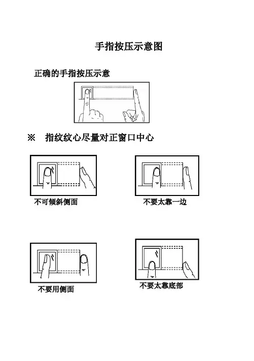
手指按压示意图正确的手指按压示意※指纹纹心尽量对正窗口中心不可倾斜侧面不要太靠一边不要太靠底部不要用侧面技术指标目录1、指纹考勤机的基本操作 (1)1.1指纹考勤机的用户 (1)1.2指纹考勤机的登记方式 (1)1.3指纹考勤机的密码 (1)1.4指纹考勤机的工作状态 (1)1.5指纹考勤机记录的数据 (2)1.6指纹考勤机的功能设置 (3)1.6.1 系统设置 (3)1.6.2 记录设置 (4)1.6.3 通讯设置 (5)2、指纹考勤机的一般操作 (5)2.1键盘 (5)2.2菜单 ..........................................................................错误!未定义书签。
2.3菜单结构图 (6)2.4第一次使用时的操作 (9)2.5考勤状态下的使用方法 (9)2.6管理者操作状态的操作步骤 (11)3、指纹考勤机的管理者操作方法 (12)3.1数据管理 (13)3.1.1 用户登记 (13)3.1.2 指纹登记 (15)3.1.2.1 新用户登记 (15)3.1.2.2 备份登记 (17)3.1.3密码登记 (20)3.1.3.1 新用户登记 (21)3.1.3.2 备份登记 (22)3.1.4 指纹及密码 (23)3.1.4.1 新用户登记 (23)3.1.4.2 备份登记 (25)3.1.5 管理者登记 (25)3.1.6 删除登记数据 (26)3.1.7 查看考勤记录 (28)3.1.8 查看管理记录 (29)3.1.9 删除全部记录 (29)3.2设置 (30)3.2.1 系统设置 (31)3.2.2 管理者总数 (31)3.2.3 机号 (32)3.2.4 时间设置 (33)3.2.5 语言 (33)3.2.6 锁驱动 (33)3.2.7 自动关机 (34)3.2.8 记录设置 (34)3.2.9 管理记录警告 (34)3.2.10 考勤记录警告 (35)3.2.11 重复确认时间 (35)3.2.12 通讯设置 (35)3.2.13 波特率 (36)3.2.14 奇偶校验 (36)3.2.15 停止位 (36)3.2.16 系统信息 (36)4、与计算机通信 (38)4.1连接指纹考勤机 (38)4.2考勤统计 ..................................................................错误!未定义书签。

Siebel实用工具软件用户手册汉得信息技术股份有限公司版本号:V1.0 Beta版序言Siebel实用小工具是基于基于Microsoft .NET Framework开发的一个小软件,目的在于提高日常项目实施中的工作效率,避免一些重复性的劳动.其主要功能有:对文本的各种简单处理,最常用的有,对数据进行OR连接,可以方便的实现在siebel应用的查询,对数据进行sql中in字句的连接,可以方便的将数据插入到sql的语句中。
对文本进行按照给定数据的拆分,以及替换,使用非常方便快捷。
对文本进行查重、去重、对比等各种功能。
对剪贴板进行监控,可以方便的获取数据,方便的生成ldap的ldif文件、db的sql脚本等可以按照模板发送邮件等,可以用在期初上线发送用户名以及密码给客户。
可以获取数据库中的eScript脚本第一章软件安装与初始化Siebel实用小工具是一个免安装工具,双击运行目录下的Siebel实用工具.exe即可运行。
但是前提是您的电脑中安装有Microsoft .NET Framework,否则程序无法打开启动页面,可能会报如下错误:/downloads/zh-cn/details.aspx?FamilyID=39C8B6 3B-F64B-4B68-A774-B64ED0C32AE7可通过以上地址下载安装Microsoft .NET Framework。
若可以成功打开,则能看到如下界面:第二章操作说明2.1 期初配置2.2 功能说明2.2.1 文本操作2.2.2 其它操作2.1 参数配置文件在软件的目录下面有文件夹config下面对每个参数做一个简单的讲解:●emailLAddressform:用与发送邮件的时候使用,可不填写!●emailLAddressto:用与发送邮件的时候使用,可不填写!●emailLAddresspassword:用与发送邮件的时候使用,可不填写!●emailLAddresssmtp:用与发送邮件的时候使用,可不填写!●REG_HOT_KEY:用户判断是否开启注册SHIFT+X按键的热键●DEVPODBCDCN:配置一个开发环境的odbc信息,用户获取脚本时使用,可不填写●DEVPODBCDataBase配置一个开发环境的odbc信息,用户获取脚本时使用,可不填写●DEVPODBCUID配置一个开发环境的odbc信息,用户获取脚本时使用,可不填写●DEVPODBCPWD配置一个开发环境的odbc信息,用户获取脚本时使用,可不填写2.2.1 文本功能操作如图所示,在图中上方的框中随便输入一段信息,点击【使用OR连接】,可以得到以OR连接的方便siebel查询的字符串。
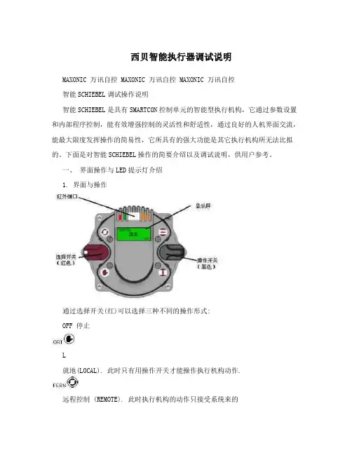
西贝智能执行器调试说明MAXONIC 万讯自控 MAXONIC 万讯自控 MAXONIC 万讯自控智能SCHIEBEL调试操作说明智能SCHIEBEL是具有SMARTCON控制单元的智能型执行机构,它通过参数设置和内部程序控制,能有效增强控制的灵活性和舒适性,通过良好的人机界面交流,能最大限度发挥操作的简易性,它所具有的强大功能是其它执行机构所无法比拟的。
下面是对智能SCHIEBEL操作的简要介绍以及调试说明,供用户参考。
一、界面操作与LED提示灯介绍1. 界面与操作通过选择开关(红)可以选择三种不同的操作形式:OFF 停止L就地(LOCAL). 此时只有用操作开关才能操作执行机构动作.远程控制 (REMOTE). 此时执行机构的动作只接受系统来的信号,不受操作开关的就地控制,但可查阅菜单. 如果须手动操作执行机构,请勿必先将两开关放到中间位置~再压下手柄,转动手轮即可实现手动(手动时禁止将红色选择开关打到状态~执行机构在电动运行状态时禁止压手柄~),如遇手柄压不下去,请先空转手轮再压手柄。
根据选择开关的位置,操作开关就能获得不同的功能:选择开关在“OFF”位置:操作开关被用来上、下翻动菜单,操作开关从中间旋向的方向,可用来观察数据记录状态(S项及H项) ,从中间旋向的方向可以观察参数菜单(P项)与您共享世界新技术成果 We build automation success in ChinaPage 1MAXONIC 万讯自控 MAXONIC 万讯自控 MAXONIC 万讯自控在菜单里,选择开关具有对实际输入的确认和取消的功能,选择开关15度的旋转可用来确认或取消参数项里的各种输入(如果要修改参数请注意将左下角的“edit”变为“save”才能修改,如果要确认参数请注意将“save”变为“edit”).如果在菜单中想快速返主界面,请将操作开关放到中间,选择开关打到L位置后即可。
选择开关在“REMOTE”位置这个状态是远程控制状态,通过操作开关只可观察不同的数据记录,不能进行参数的设定选择开关在“LOCAL”位置操作开关被用来控制执行机构,既可以将开关置于机械保持位置使执行机构做持续运动,也可以通过小幅偏转使执行机构点动,.点动时操作开关都能通过弹簧回到中间位置2. LED指示灯各指示灯不同状态所表示的含义名称颜色亮闪烁不亮L1 红开正在开启没到开位L2 绿关正在关闭没到关位L3 黄转矩正常转矩故障 ---------------L4 黄就绪报警故障二、参数菜单项说明在执行机构菜单中共有P项(组态参数)、S项(数据记录)和H项(历史记录),P 项在后面调试说明和参数设置中将详细讲述。

Models:Copyright © 2012 by Schilling Robotics, LLC. All rights reserved.Schilling Robotics, the FMC Technologies logo, and their frameworks are trademarks and service trademark applications of FMC Technologies. No part of this document may be reproduced or used in any form without the express written permission of FMC Technologies. Descriptions and specifications are subject to change without notice.FMC Technologies Schilling Robotics260 Cousteau Place, Suite 200, Davis, CA 95618 • Ph: (530) 753-6718 • Fax: (530) 753-8092 E-mail: ******************* • ************************** • Customer**********************Web Site: TECHNICAL MANUAL REVISION LOGTitan 4 Manipulator System, Model Nos. 199-0295, 0295PAL, 0296, 0299,0299-1, 0300, 0301, 0302, 0307, 0308-1, 2, 3, 4, 7, 8TECHNICAL MANUAL: 011–8239Description Date Rev.Manual release March, 2012AT4 O7P compatible, 8 pin 20 shell burton connector June, 2012BTable of ContentsSpecifications1 System. . . . . . . . . . . . . . . . . . . . . . . . . . . . . . . . . . . . . . . . .91.1 Electrical. . . . . . . . . . . . . . . . . . . . . . . . . . . . . . . . . . . . . . . 91.2 Telemetry . . . . . . . . . . . . . . . . . . . . . . . . . . . . . . . . . . . . . . 92 Password. . . . . . . . . . . . . . . . . . . . . . . . . . . . . . . . . . . . . . .93 Slave Arm . . . . . . . . . . . . . . . . . . . . . . . . . . . . . . . . . . . . .103.1 Specifications . . . . . . . . . . . . . . . . . . . . . . . . . . . . . . . . . . 103.2 Electrical. . . . . . . . . . . . . . . . . . . . . . . . . . . . . . . . . . . . . . 103.3 Slave Arm Functions. . . . . . . . . . . . . . . . . . . . . . . . . . . . . . 103.4 Slave Arm Dimensions & Range of Motion. . . . . . . . . . . . . . . 113.5 Sensor . . . . . . . . . . . . . . . . . . . . . . . . . . . . . . . . . . . . . . . 114 Master Controller. . . . . . . . . . . . . . . . . . . . . . . . . . . . . . . .114.1 Specifications . . . . . . . . . . . . . . . . . . . . . . . . . . . . . . . . . . 114.2 Electrical. . . . . . . . . . . . . . . . . . . . . . . . . . . . . . . . . . . . . . 115 Environmental. . . . . . . . . . . . . . . . . . . . . . . . . . . . . . . . . .116 Hydraulics . . . . . . . . . . . . . . . . . . . . . . . . . . . . . . . . . . . . .116.1 Fluids . . . . . . . . . . . . . . . . . . . . . . . . . . . . . . . . . . . . . . . . 116.2 System Requirements. . . . . . . . . . . . . . . . . . . . . . . . . . . . . 127 Compensation . . . . . . . . . . . . . . . . . . . . . . . . . . . . . . . . . .128 Custom Features or Modifications. . . . . . . . . . . . . . . . . . .12 Installation1 User-Supplied Equipment . . . . . . . . . . . . . . . . . . . . . . . . .132 Installation Overview . . . . . . . . . . . . . . . . . . . . . . . . . . . .133 Mechanical Installation. . . . . . . . . . . . . . . . . . . . . . . . . . .133.1 Slave Arm. . . . . . . . . . . . . . . . . . . . . . . . . . . . . . . . . . . . . 133.2 Compensator. . . . . . . . . . . . . . . . . . . . . . . . . . . . . . . . . . . 143.3 Junction Box . . . . . . . . . . . . . . . . . . . . . . . . . . . . . . . . . . . 153.4 Master Controller. . . . . . . . . . . . . . . . . . . . . . . . . . . . . . . . 164 Electrical Power & Telemetry Connections . . . . . . . . . . . .164.1 Telemetry Configuration . . . . . . . . . . . . . . . . . . . . . . . . . . . 164.2 Long-Line Connections . . . . . . . . . . . . . . . . . . . . . . . . . . . . 16Page 34.3 Deck-Test Connections . . . . . . . . . . . . . . . . . . . . . . . . . . . .185 Completing the Installation. . . . . . . . . . . . . . . . . . . . . . . .19Operation1 The Master Controller. . . . . . . . . . . . . . . . . . . . . . . . . . . . .231.1 Master Arm . . . . . . . . . . . . . . . . . . . . . . . . . . . . . . . . . . . .241.2 LCD Display Screen. . . . . . . . . . . . . . . . . . . . . . . . . . . . . . .241.3 Function Keys. . . . . . . . . . . . . . . . . . . . . . . . . . . . . . . . . . .241.4 Control Keys. . . . . . . . . . . . . . . . . . . . . . . . . . . . . . . . . . . .241.5 Power Switch . . . . . . . . . . . . . . . . . . . . . . . . . . . . . . . . . . .241.6 Auxiliary Jaw Switch . . . . . . . . . . . . . . . . . . . . . . . . . . . . . .251.7 Menu Structure. . . . . . . . . . . . . . . . . . . . . . . . . . . . . . . . . .251.8 Baud Rate . . . . . . . . . . . . . . . . . . . . . . . . . . . . . . . . . . . . .262 Using the Master Controller. . . . . . . . . . . . . . . . . . . . . . . .262.1 Master Arm . . . . . . . . . . . . . . . . . . . . . . . . . . . . . . . . . . . .262.2 Slave Arm Status . . . . . . . . . . . . . . . . . . . . . . . . . . . . . . . .272.3 Controlling Slave Arm Hydraulics . . . . . . . . . . . . . . . . . . . . .282.4 Controlling Auxiliary Equipment . . . . . . . . . . . . . . . . . . . . . .292.5 Menu Security. . . . . . . . . . . . . . . . . . . . . . . . . . . . . . . . . . .292.6 Incompatibility Alert Screens . . . . . . . . . . . . . . . . . . . . . . . .293 Operation. . . . . . . . . . . . . . . . . . . . . . . . . . . . . . . . . . . . . .303.1 Pre-Start Checks. . . . . . . . . . . . . . . . . . . . . . . . . . . . . . . . .303.2 Startup . . . . . . . . . . . . . . . . . . . . . . . . . . . . . . . . . . . . . . .303.3 Using the STOW OUT Menu . . . . . . . . . . . . . . . . . . . . . . . . .323.4 Using the MAIN Menu . . . . . . . . . . . . . . . . . . . . . . . . . . . . .323.5 Using the OPERATE Menu. . . . . . . . . . . . . . . . . . . . . . . . . . .343.6 Using OPERATE Menu Options. . . . . . . . . . . . . . . . . . . . . . . .363.7 Using the SHUT DOWN Menu . . . . . . . . . . . . . . . . . . . . . . . .403.8 Shut Down Maintenance. . . . . . . . . . . . . . . . . . . . . . . . . . . .413.9 Operating the Optional Wrist Camera. . . . . . . . . . . . . . . . . . .414 Setting Performance Options. . . . . . . . . . . . . . . . . . . . . . .414.1 Using the OPTIONS Menu. . . . . . . . . . . . . . . . . . . . . . . . . . .414.2 Using the SETUP Menu. . . . . . . . . . . . . . . . . . . . . . . . . . . . .434.3 Enhancing the Slave Arm Position Data Stream . . . . . . . . . . .505 System Errors & Warnings. . . . . . . . . . . . . . . . . . . . . . . . .505.1 Startup with System Warnings . . . . . . . . . . . . . . . . . . . . . . .505.2 Startup with System Errors . . . . . . . . . . . . . . . . . . . . . . . . .515.3 ERR (Error) Message During Operation . . . . . . . . . . . . . . . . .525.4 Using the SHOW ERRORS Menu . . . . . . . . . . . . . . . . . . . . . .525.5 Enabling & Disabling System Error Checking. . . . . . . . . . . . . .555.6 Diagnosing Master/Slave Problems . . . . . . . . . . . . . . . . . . . .565.7 Fatal Telemetry Errors. . . . . . . . . . . . . . . . . . . . . . . . . . . . .566 Avoiding Slave Arm Damage . . . . . . . . . . . . . . . . . . . . . . .56 Troubleshooting1 Preliminary Fault Isolation Procedures. . . . . . . . . . . . . . .57Page 4Table of Contents1.1 Definitions. . . . . . . . . . . . . . . . . . . . . . . . . . . . . . . . . . . . . 572 Diagnosing Master/Slave Joint Problems. . . . . . . . . . . . .582.1 Uncontrolled Operation. . . . . . . . . . . . . . . . . . . . . . . . . . . . 582.2 The Stow In/Stow Out Test. . . . . . . . . . . . . . . . . . . . . . . . . 582.3 Diagnosis with the MASTER TEST Screen . . . . . . . . . . . . . . . 592.4 Diagnosis with the Slave Test Screen . . . . . . . . . . . . . . . . . . 603 Diagnosing Key and Freeze Button Failures . . . . . . . . . . .624 Troubleshooting Tables. . . . . . . . . . . . . . . . . . . . . . . . . . .634.1 Screen-Displayed Symptoms. . . . . . . . . . . . . . . . . . . . . . . . 634.2 Master Arm Symptoms. . . . . . . . . . . . . . . . . . . . . . . . . . . . 654.3 Slave Arm Symptoms (Entire Arm). . . . . . . . . . . . . . . . . . . . 664.4 Slave Arm Symptoms (Individual Joints). . . . . . . . . . . . . . . . 674.5 Jaw Symptoms . . . . . . . . . . . . . . . . . . . . . . . . . . . . . . . . . 684.6 System Errors . . . . . . . . . . . . . . . . . . . . . . . . . . . . . . . . . . 694.7 Fatal Telemetry Errors . . . . . . . . . . . . . . . . . . . . . . . . . . . . 715 Using the Status Indicator LEDs . . . . . . . . . . . . . . . . . . . .725.1 Slave Controller PCB LEDs. . . . . . . . . . . . . . . . . . . . . . . . . . 725.2 Master Controller PCB Status LEDs. . . . . . . . . . . . . . . . . . . . 726 Master Controller Voltage Test Points. . . . . . . . . . . . . . . .737 Factory Assistance. . . . . . . . . . . . . . . . . . . . . . . . . . . . . . .74 Maintenance & Service1 Safety First . . . . . . . . . . . . . . . . . . . . . . . . . . . . . . . . . . . .751.1 Worksite Safety. . . . . . . . . . . . . . . . . . . . . . . . . . . . . . . . . 751.2 Electrical Safety. . . . . . . . . . . . . . . . . . . . . . . . . . . . . . . . . 761.3 Mechanical Safety . . . . . . . . . . . . . . . . . . . . . . . . . . . . . . . 761.4 Hydraulic Safety. . . . . . . . . . . . . . . . . . . . . . . . . . . . . . . . . 761.5 Deck Testing . . . . . . . . . . . . . . . . . . . . . . . . . . . . . . . . . . . 772 Service Guidelines. . . . . . . . . . . . . . . . . . . . . . . . . . . . . . .772.1 Service Assumption . . . . . . . . . . . . . . . . . . . . . . . . . . . . . . 772.2 Guidelines. . . . . . . . . . . . . . . . . . . . . . . . . . . . . . . . . . . . . 782.3 Startup After Maintenance or Service . . . . . . . . . . . . . . . . . . 793 Maintenance . . . . . . . . . . . . . . . . . . . . . . . . . . . . . . . . . . .803.1 Daily Maintenance . . . . . . . . . . . . . . . . . . . . . . . . . . . . . . . 803.2 Long Term Periodic Maintenance . . . . . . . . . . . . . . . . . . . . . 803.3 Cable & Penetrator Maintenance . . . . . . . . . . . . . . . . . . . . . 814 Junction Box Service. . . . . . . . . . . . . . . . . . . . . . . . . . . . .824.1 Fuse Replacement . . . . . . . . . . . . . . . . . . . . . . . . . . . . . . . 825 Master Controller Service & Configuration . . . . . . . . . . . .825.1 Accessing Internal Components. . . . . . . . . . . . . . . . . . . . . . 825.2 Adjusting the LCD Screen Viewing Angle. . . . . . . . . . . . . . . . 835.3 Changing the System Baud Rate . . . . . . . . . . . . . . . . . . . . . 835.4 Master Controller Software Selection . . . . . . . . . . . . . . . . . . 845.5 Incompatibility Alert Screens. . . . . . . . . . . . . . . . . . . . . . . . 86Table of Contents Page 56 Slave Arm Service . . . . . . . . . . . . . . . . . . . . . . . . . . . . . . .896.1 Slave Arm Filter Replacement and Cleaning . . . . . . . . . . . . . .896.2 Emergency Manual Slave Arm Manipulation . . . . . . . . . . . . . .916.3 Recovery from Water Intrusion. . . . . . . . . . . . . . . . . . . . . . .926.4 Remove & Install Optional Camera . . . . . . . . . . . . . . . . . . . .947 System Adjustments & Configuration . . . . . . . . . . . . . . . .977.1 Setting Servo Valve Voltage Offsets. . . . . . . . . . . . . . . . . . . .977.2 Changing the Communication Protocol. . . . . . . . . . . . . . . . . .987.3 Changing the System Baud Rate. . . . . . . . . . . . . . . . . . . . . 1008 Service & Work Instructions . . . . . . . . . . . . . . . . . . . . . 1008.1 Index. . . . . . . . . . . . . . . . . . . . . . . . . . . . . . . . . . . . . . . . 1018.2 Instructions for Serviceable Components. . . . . . . . . . . . . . . 1018.3 Startup Following Maintenance or Service . . . . . . . . . . . . . . 101 Drawings & Part Lists1 Organization. . . . . . . . . . . . . . . . . . . . . . . . . . . . . . . . . . 1432 Index . . . . . . . . . . . . . . . . . . . . . . . . . . . . . . . . . . . . . . . 1432.1 Manipulator System. . . . . . . . . . . . . . . . . . . . . . . . . . . . . . 1432.2 Deck Test Cables. . . . . . . . . . . . . . . . . . . . . . . . . . . . . . . . 1432.3 Slave Arm . . . . . . . . . . . . . . . . . . . . . . . . . . . . . . . . . . . . 1442.4 Master Controller . . . . . . . . . . . . . . . . . . . . . . . . . . . . . . . 1452.5 Junction Box. . . . . . . . . . . . . . . . . . . . . . . . . . . . . . . . . . . 1452.6 Hydraulic Compensator . . . . . . . . . . . . . . . . . . . . . . . . . . . 1452.7 Spares Kits. . . . . . . . . . . . . . . . . . . . . . . . . . . . . . . . . . . . 1453 Reference Drawings. . . . . . . . . . . . . . . . . . . . . . . . . . . . 1454 Spares Kits. . . . . . . . . . . . . . . . . . . . . . . . . . . . . . . . . . . 2944.1 Standard Spares Kits. . . . . . . . . . . . . . . . . . . . . . . . . . . . . 2944.2 Enhanced Spares Kits . . . . . . . . . . . . . . . . . . . . . . . . . . . . 3034.3 Enhanced Spares Sub-Kits . . . . . . . . . . . . . . . . . . . . . . . . . 307Page 6Table of ContentsSafety & Service SummaryPrecautionary NoticesThis manual provides precautionary notices which carry important information about safety risks to personnel and damage to equipment while installing, operating, servic-ing, or maintaining this equipment.The form and significance of the notices are shown below.!WARNINGA WARNING alerts you to a risk of injury or loss of life. It may also include instructions to help minimize or eliminate the risk.!CautionA CAUTION alerts you to a risk of equipment damage or loss.It may also include instructions to help minimize or elimi-nate the risk.NOTE: The absence of WARNING and CAUTION notices does not meanthat risk is absent. Always use appropriate safety procedures, equipment,and personal protective equipment (PPE) when operating and servicing thisequipment.Service AssumptionThis manual assumes that service personnel are familiar with the general operating principles, safety guidelines, and service practices associated with the types of equip-ment represented in this manual.Table of Contents Page 7Security PasswordModel No.__________________________Serial No.__________________________Level 5 PasswordThis is your level 5 password: 1357!WARNINGMisuse of the menus accessible with this password cancause malfunctions of the manipulator system, injury to per-sonnel, and/or damage to equipment.The password for security level 5 is set at the factory and cannot be changed. It pro-vides access to all configurable system menus, including those for setting other secu-rity levels and passwords for other operators. See the OPERATION module in your technical manual for complete information on how to use the level 5 password. Temporary Password, Levels 1-4The temporary password 0000 is provided for access to security levels 1 through 4 during installation and first startup. This password can be changed to meet your security level requirements.Security Level 0Security level 0 is the default level, always available at system startup and requiring no password. While permitting operation, it restricts access to almost all system con-figuration menus and security features. An operator using a correctly configured manipulator should need no higher privilege level. Levels above 0 require passwords and allow access to specific manipulator system configuration menus.Page 8Table of ContentsSpecificationsIn This Chapter:•1System.........................................................................page 9•2Password.......................................................................page 9•3Slave Arm...................................................................page 10•4Master Controller..........................................................page 11•5Environmental..............................................................page 11•7Compensation..............................................................page 12•8Custom Features or Modifications...................................page 12NOTE: The specifications in this chapter apply to the systems listed on the title page, ex-cept as noted. The components specific to each system are itemized in the 199-level partlists at the end of the “Drawings & Part Lists” chapter.1System1.1ElectricalSystem supply at junction box . . . . . . . . . 90 to 260 VAC, 50-60 Hz, single-phase1.2TelemetryDefault protocol . . . . . . . . . . . . . . . . . . . . . . . . . . . . . . . . . . . . . . . . . . . . . . . . . RS-232User-selectable option. . . . . . . . . . . . . . . . . . . . . . .RS-422/-485 half-duplex 2-wireNOTE: RS-485 full-duplex telemetry (4-wire) is not supported.Default baud . . . . . . . . . . . . . . . . . . . . . . . . . . . . . . . . . . . . . . . . . . . . . . . . . . . . . 19200User-selectable options . . . . . . . . . . . . . . . . . . . . . . . . . . . . . 57600 and 115200 baudNOTE: At 57600 and 115200 baud, additional slave arm joint position data is added toeach data packet, however third-party software is needed to utilize it.2PasswordAccess to some master controller menus is password protected. A password information sheet follows the “Table of Contents” section.011–0929Page 9• Specifications3Slave Arm3.1SpecificationsDepth rating . . . . . . . . . . . . . . . . . . . . . . . . . . . . . . . . . . . . . . 4,000 msw (13,124 fsw)Maximum reach . . . . . . . 1,922 mm (75.7 in.) (from azimuth to gripper T-bar slot)Weight in air . . . . . . . . . . . . . . . . . . . . . . . . . . . . . . . . . . . . . . . . . . . . . 100 kg (221 lb)Weight in seawater . . . . . . . . . . . . . . . . . . . . . . . . . . . . . . . . . . . . . . . . . 78 kg (174 lb)NOTE: Performance specifications use the standard system configuration with ShellTellus Oil 32 hydraulic fluid, input pressure of 207 bar (3,000 psi) and available flow of19 lpm (5 gpm).Lift at full extension, nominal. . . . . . . . . . . . . . . . . . . . . . . . . . . . . . . 122 kg (270 lb)Maximum lift, nominal . . . . . . . . . . . . . . . . . . . . . . . . . . . . . . . . . . 454 kg (1,000 lb)Maximum gripper opening (standard gripper), nominal . . . . . . . . 99 mm (3.9 in.)Grip force, nominal . . . . . . . . . . . . . . . . . . . . . . . . . . . . . . . . . . . . . 4,092 N (920 lbf)Wrist torque, nominal . . . . . . . . . . . . . . . . . . . . . . . . . . . . . . . . . . 170 Nm (125 ft-lb)Wrist rotation, continuous . . . . . . . . . . . . . . . . . . . . . . . . . . . . . . . . . 360°, 6-35 rpm3.2ElectricalConnectorThe slave arm connector to system power and telemetry varies with the Titan 4 model. See the 199- part list for this system model.Input power:Slave arm. . . . . . . . . . . . . . . . . . . . . . . . . . . . . . . . . . . . . . . . . . . . . . . . . . . . . . . 24 VDC Power consumption:Slave in-arm controller plus solenoid . . . . . . . . . . . . . . . . . . . . 6 W start, 12 W runSlave arm current draw . . . . . . . . . . . . . . . . . . . . . . . . . . . . . . . . . 1.875 A, at 24 VDC3.3Slave Arm FunctionsAzimuth Rotary240°Shoulder pitch Linear120°Elbow pitch Rotary270°Wrist pitch Rotary180°Wrist yaw Rotary180°Wrist rotate Gerotor360° continuousJaw (standard)Linear99mm (3.9-in.)Page 10 • Slave Arm 011–0929Specifications •011–0929 Master Controller • Page 113.4Slave Arm Dimensions & Range of MotionSee the slave arm drawing in the “Drawings & Part Lists” chapter for:Ranges of motionExtended dimensionsStow dimensions Mounting dimensions3.5SensorWater detection . . . . . . . . . . . . . . . . . . . . . . . . . . . . . . . . . . . . . . . . . . . . . . . . .forearm 4Master Controller4.1SpecificationsLength . . . . . . . . . . . . . . . . . . . . . . . . . . . . . . . . . . . . . . . . . . . . . . . . 470 mm (18.5 in.)Width . . . . . . . . . . . . . . . . . . . . . . . . . . . . . . . . . . . . . . . . . . . . . . . . . 177 mm (7.0 in.)Height . . . . . . . . . . . . . . . . . . . . . . . . . . . . . . . . . . . . . . . . . . . . . . . . . . 67 mm (2.6 in.)Weight . . . . . . . . . . . . . . . . . . . . . . . . . . . . . . . . . . . . . . . . . . . . . . . . . . . 3.7 kg (8.2 lb)4.2ElectricalInput power:Master controller . . . . . . . . . . . . . . . . . . . . 90 to 260 VAC, 50-60 Hz, single-phase Power consumption:Master controller . . . . . . . . . . . . . . . . . . . . . . . . . . . . . . . . . . . . . . 6 W start, 3 W run 5EnvironmentalOperating temperature . . . . . . . . . . . . . . . . . . . . . . . . -2 to +54° C (+28 to +130° F)Storage temperature . . . . . . . . . . . . . . . . . . . . . . . . . . -15 to +71° C (+5 to +160 ° F)Humidity. . . . . . . . . . . . . . . . . . . . . . . . . . . . . . . . . . . . . . . . . 0% to 100% condensing 6Hydraulics6.1FluidsSelect a hydraulic fluid based on its maximum temperature during normal operations.Lower than 54°C (130°F): Use 22 grade oil.Higher than54°C (130°F): Use 32 grade oil. For temperatures above 71°C (160°F), below 0°C (32°F), or when in doubt about which fluid to use, contact your regional technical support representative.Do not use water-based fluids.If a fluid has been specified for this system to meet special environmental or oper-ational requirements, use it and disregard the parameters listed above.• Specifications6.2System RequirementsViscosity. . . . . . . . . . . . . . . . . . . . . . . . . . . . . . . . . . . . . . . . . . . . . . . . . . . . 10 - 200 cStAvailable flow . . . . . . . . . . . . . . . . . . . . . . . . . . . . . . . . .5.7 - 19.0 lpm (1.5 - 5.0 gpm)Pressure. . . . . . . . .103 bar (1,500 psi) minimum to 207 bar (3,000 psi) maximumNOTE: Slave arm performance specifications are determined at maximum pressureand flow. Performance diminishes when pressure or flow are reduced.Hydraulic fluid temperature, maximum . . . . . . . . . . . . . . . . . . . . . . . .54° C (130° F)Return pressure, maximum . . . . . . . . . . . . . . . . . . . . . . . . . . . . . . 34.5 bar (500 psi)Filtration, hydraulic supply. . . . . . . . . . . . . . . . . . 3 microns (10 microns absolute)NOTE: Use of the recommended filtration will reduce the need to clean or replace theslave arm’s internal hydraulic filter (10 microns, 25 microns absolute).Return relief valve cracking pressure, nominal . . . . . . . . . . . . . . 500 psi (34.5 bar)Customer-supplied mating fittings required:Supply hose fitting -4 JIC female, 1/4-in.Return hose fitting -6 JIC female, 3/8-in.7CompensationFluid requirement . . . . . . . . . . . . . . . . . . . . . . . . Non-conductive, non-water basedCompensator fluid capacity. . . . . . . . . . . . . . . . . . . . . . . . . . . . . . . . . . 2.2 l (0.58 gal)Slave arm fluid capacity. . . . . . . . . . . . . . . . . . . . . . . . . . . . . . . . . . . . . 9.6 l (2.54 gal)System total fluid capacity. . . . . . . . . . . . . . . . . . . . . . . . . . . . . . . . . . 11.8 l (3.12 gal.)Fluid pressure (above ambient) . . . . . . . . . . . . . . . . . . 0.48 to 0.69 bar (7 to 10 psi)Relief valve cracking pressure, nominal . . . . . . . . . . . . . . . . . . . . . . .1.4 bar (20 psi)8Custom Features or ModificationsAny custom features or modifications present on the supplied Manipulator System are described on the following page(s).Page 12 • Compensation 011–0929。

EasyBelt and FlexiBelt are used for sitting transfers or as support when the user is standing or walking.SystemRoMedic’s EasyBelt and FlexiBelt, are used for sit-to-stand transfers or for moving from the wheelchair to the bed, toilet or car. Both models are available in several sizes. FlexiBelt, hug is a new version with a patent applied for design which makes the belt ”hug” on to the user instead of sliding up.Originalmodels And a new hugging versionBelts for supportSturdy finished edge increases longevity of the product.The handles are ergonomically designed to provide the best possible grip.In exposed areas, the seams are reinforced.This innerside is anti-slip treated, which keeps the belt in position preventing slippage.The tightening strap is sturdy and easy to adjust.A good, strong grip around the waist is often all that is needed.In many transfer situations a firm and helping hand is exactly what is needed. SystemRoMedic’s EasyBelt and FlexiBelt are used for sit-to-stand transfers or for transfer from the wheelchair to the bed, toilet or car. It's all about a little firm support and help when it's most needed.Firm grip in two versionsThe belt, which is placed around the user’s waist or hips, has mul-tiple, sturdy handles, both vertically and horizontally, providing the carer with a firm grip in various situations. The belt is available in two models. EasyBelt has an anti-slip inside of PU-coated nylon and can therefore be used in environments where moisture and damp-ness are present or when there are special hygiene requirements. FlexiBelt has a soft innerside of polyester velvet which makes it very comfortable to wear.For heavy transfers, the belt can be combined with other devicesFor transfers that are heavy and complex, the belt can easily be used in combination with other devices. Sitting transfers can be made with a little extra help from a sliding mat like EasySlide or a sliding board like EasyGlide. EasyBelt and FlexiBelt make life easier for both user and carer, and they have positive effects on the way in which both parties work together in everyday situations.FlexiBeltFlexiBelt has a soft innerside,making the belt comfortable.EasyBeltEasyBelt has an inside of PU-coated nylon which prevents slipping against clothes and repelsmoisture and water.FlexiBeltFlexiBelt has a soft polyester velvet innerside, making the belt verycomfortable to wear.EasyBelt and FlexiBelt are used as support when the user is standing or walking. It's all about a little firm support and help when it's most needed.The quick-connect buckle is strong and safe and easy to open, close and tighten.The outer material ismade of durable nylon for maximum product life.Vertical and horizontal handles enable easy accessand a good grip from allpositions.FlexiBelt, hugFlexiBelt, hug features a new patent applied for design which makes the belt "hug" on to the user instead of sliding up.New!New! FlexiBelt, hugFlexiBelt, hug is a new version of SystemRoMedic’s classic FlexiBelt. Flexi-Belt, hug features a new, patented design with horizontal handles that slide freely in loops to make the belt “hug” on to the user instead of sliding up during transfer situations. With FlexiBelt, hug, the carer can provide even more support without using more effort. The new design actually does all the work by itself.QUICK REFERENCEEasyBelt and FlexiBelt are used for sitting transfers or as support when the user is standing or walking. Outer material: nylon. Inside material: FlexiBelt, polyester velvet and EasyBelt, moisture-repellent PU-coated nylon. EasyBelt is recommended in environments with special hygiene requirements, while FlexiBelt has a softer and more pleasant surface against the body. SupportStraps is a multi-functional accessory providing extra support and security for users during standing, gait training and transfers with SystemRoMedic belts, sit-to-stand aids and transfer platforms. SupportStraps can be used as leg harness for EasyBelt and FlexiBelt, effectively preventing the belt from sliding upwards during transfer or gait trainingArt. No. Product Size Measurement Waist measurement Handles 6012 EasyBelt XS 75 cm / 29,5" 45–70 cm/18”-28” 5 pcs 6013 EasyBelt S 105 cm / 41,3" 60–100 cm/24”-40” 7 pcs 6014 EasyBelt M 120 cm / 47,2" 70–120 cm/28”-48” 9 pcs 6015 EasyBelt L 135 cm / 53,1" 100–160 cm/40”-64” 11 pcs6023 FlexiBelt S 105 cm / 41,3" 60–100 cm/24”-40” 7 pcs 6024 FlexiBelt M 120 cm / 47,2" 70–120 cm/28”-48” 9 pcs 6025 FlexiBelt L 135 cm / 53,1" 100–160 cm/40”-64” 11 pcs 6026 FlexiBelt XL 150 cm / 59,1" 115–175 cm/46"-70" 13 pcs 6072 FlexiBelt, hug XS 75 cm / 29,5" 45–70 cm/18”-28” 5 pcs ( 3 + 2 movable ) 6073 FlexiBelt, hug S 105 cm / 41,3" 60–100 cm/24”-40” 7 pcs ( 4 + 3 movable ) 6074 FlexiBelt, hug M 120 cm / 47,2" 70–120 cm/28”-48” 9 pcs ( 5 + 4 movable ) 6075 FlexiBelt, hug L 135 cm / 53,1" 100–160 cm/40”-64” 11 pcs ( 6 + 5 movable )encompasses four product areas that meet most needs in different transfer situations.Transfer, between two locations. Positioning, within the same location.Support, for mobility. Lifting, both manual and mechanical.。
t e r y o u rn e w d e v i c eo nM y B o s c h no w a n dg e t f r e e b en e f i t s:b o sc h-h o me.c o m/w e l c o m e Warming drawerBIC510N.0BID510N.0[en]User manual and installation instructionsen Safety2Table of contentsINFORMATION FOR USE 1Safety.................................................................... 22Preventing material damage ............................... 33Environmental protection and saving en-ergy....................................................................... 34Familiarising yourself with your appliance........ 45Before using for the first time............................. 46Tableware............................................................. 47Basic operation.................................................... 58Preheating tableware........................................... 59Keeping food warm.............................................. 510Cleaning and servicing........................................ 611Troubleshooting................................................... 612How it works......................................................... 713Customer Service. (814)INSTALLATION INSTRUCTIONS (9)14.4Safe installation .................................................101 SafetyObserve the following safety instructions.1.1 General information¡Read this instruction manual carefully.¡Keep the instruction manual and the product information safe for future refer-ence or for the next owner.¡Do not connect the appliance if it has been damaged in transit.1.2 Intended useThis appliance is designed only to be built into kitchen units. Read the special installation instructions.Only a licensed professional may connect ap-pliances without plugs. Damage caused by in-correct connection is not covered under the warranty.Only use this appliance:¡To keep food warm and to warm cookware.¡In private households and in enclosed spaces in a domestic environment.¡Up to an altitude of max. 4000 m abovesea level.Do not use the appliance:¡On boats or in vehicles.¡with an external timer or a remote control.1.3 Restriction on user groupThis appliance may be used by children aged 8 or over and by people who have reduced physical, sensory or mental abilities or inad-equate experience and/or knowledge,provided that they are supervised or have been instructed on how to use the appliance safely and have understood the resulting dangers.Do not let children play with the appliance.Children must not perform cleaning or user maintenance unless they are at least 15 years old and are being supervised.Keep children under the age of 8 years away from the appliance and power cable.1.4 Safe useWARNING ‒ Risk of fire!The inside of the appliance gets very hot and may cause flammable materials to ignite.▶Never place flammable objects or plasticcontainers in the appliance.WARNING ‒ Risk of burns!The accessories and cookware become very hot during operation.▶Always use oven gloves when removing hot accessories or cookware from the ap-pliance.The inside of the appliance becomes very hot during operation.▶Never touch the inside of the appliance while it is hot.▶Keep children away from the appliance.The appliance becomes hot during operation.▶Allow the appliance to cool down beforecleaning.WARNING ‒ Risk of electric shock!Incorrect repairs are dangerous.▶Repairs to the appliance should only be carried out by trained specialist staff.▶Only use genuine spare parts when repair-ing the appliance.▶If the power cord of this appliance is dam-aged, it must be replaced by trained spe-cialist staff.Preventing material damage en3If the insulation of the power cord is dam-aged, this is dangerous.▶Never let the power cord come into contact with hot appliance parts or heat sources.▶Never let the power cord come into contact with sharp points or edges.▶Never kink, crush or modify the power cord.An ingress of moisture can cause an electric shock.▶Do not use steam- or high-pressure clean-ers to clean the appliance.If the appliance or the power cord is dam-aged, this is dangerous.▶Never operate a damaged appliance.▶Never pull on the power cord to unplug the appliance. Always unplug the appliance at the mains.▶If the appliance or the power cord is dam-aged, immediately unplug the power cord or switch off the fuse in the fuse box.▶Call customer services. →Page 8WARNING ‒ Risk of suffocation!Children may put packaging material over their heads or wrap themselves up in it and suffocate.▶Keep packaging material away from chil-dren.▶Do not let children play with packaging ma-terial.Children may breathe in or swallow small parts, causing them to suffocate.▶Keep small parts away from children.▶Do not let children play with small parts.2 Preventing material damageATTENTION!Excessive weight may damage the appliance.▶The appliance has a maximum load capacity of 15 kg.Moisture may damage the appliance.▶Do not use the appliance to store food and drinks.The humidity of the food may cause corrosion dam-age.3 Environmental protection and saving energy3.1 Disposing of packagingThe packaging materials are environmentally compat-ible and can be recycled.▶Sort the individual components by type and dispose of them separately.en Familiarising yourself with your appliance44 Familiarising yourself with your appliance4.1 ApplianceYou can find an overview of the parts of your appliance here.4.2 ControlsYou can use the control panel to configure all functions of your appliance and to obtain information about the 5 Before using for the first timeConfigure the settings for initial start-up. Clean the ap-pliance and accessories.5.1 Cleaning and heating up the appliance before using it for the first time1.Clean the appliance.2.Remove the accessories.3.Heat up the appliance at 80 °C for one hour.a Smoke development and odour development arenormal.6 TablewareThese instructions help you to avoid damaging your tableware.6.1 Suitable tablewareThe warming drawer has a maximum load capacity of 15 kg. You can use it to preheat the place settings for 6 or 12 people, for example.Drawer – 14 cm Drawer – 29 cm 6 dinner plates 24 cm diameter 12 dinner plates 24 cm diameter 6 soup bowls 10 cm diameter 12 soup bowls 10 cm diameter 1 bowl 19 cm diameter 1 bowl 22 cm diameter 1 bowl17 cm diameter 1 bowl 19 cm diameter 1 meat platter32 cm1 bowl17 cm diameter 2 meat platters32 cmBasic operation en57 Basic operation7.1 Opening the appliance▶Press on the centre of the warming drawer.a The warming drawer pops open and can be pulledout.7.2 Closing the appliance▶Press on the centre of the warming drawer andpush it back in.7.3 Switching on the appliance▶Press .7.4 Switching off the appliance▶Press .7.5 Setting the temperature▶Set the temperature to any value between,and .8 Preheating tablewareFood does not cool down as quickly on preheated tableware. Drinks also remain warm for longer.8.1 Starting the "Preheat tableware"functionWARNING ‒ Risk of burns!Drinking vessels become very hot at high temperat-ures.▶For drinking vessels, set the settings to.1.Place an anti-slip mat at the bottom of the drawer toprevent the tableware scratching the interior surface of the drawer.2.Place the tableware in the warming drawer.‒Distribute the tableware across the entire bottom of the warming drawer to reduce the preheating time.Do not block the ventilation opening with tall items of tableware or stacks of plates. Keeping the ventila-tion opening clear ensures that hot air can circulate efficiently.3.Turn the temperature selector to set the requiredtemperature.A setting of up to is suitable for tableware. For drinking vessels, the settings from to are suitable.4.Switch on the appliance.a The operation indicator lights up, the applianceheats up and the fan runs.5.Close the warming drawer.Note: The preheating time depends on the material,thickness, quantity and distribution of the tableware.For place settings for 6 people, the preheating time is approx. 15-25 minutes.8.2 Ending the "Preheat cookware" functionWARNING ‒ Risk of burns!The accessories and/or cookware become very hot during operation.▶Always use oven gloves to remove accessories or cookware from the cooking compartment.1.Open the warming drawer.2.Switch off the appliance.3.Remove the cookware.9 Keeping food warmYou can use the warming drawer to keep food warm for a certain period of time.We advise against keeping food warm for longer than an hour. Suitable food includes meat, poultry, fish,sauces, vegetables, side dishes and soups.9.1 Starting the "Keep food warm" functionATTENTION!Hot cookware from the hob damages the anti-slip mat in the warming drawer.▶Never take hot pots and pans off the hob and place them directly on the anti-slip mat.1.Place an anti-slip mat at the bottom of the drawer toprevent the tableware scratching the interior surface of the drawer.The anti-slip mat is food-safe. Dry food can be heated directly on the anti-slip mat in the warming drawer. The anti-slip mat must then be cleaned.2.Place the tableware in the warming drawer.3.Turn the temperature selector to set the required temperature.4.Switch on the appliance.a The operation indicator lights up, the appliance heats up and the fan runs.5.Preheat the tableware for approx. 10 minutes.6.Place food into the preheated tableware.‒Do not completely fill the tableware with food to prevent any content from spilling out when you open and close the warming drawer.‒Cover food which dries out easily with a heat-res-istant lid or aluminium foil.7.Close the warming drawer.en Cleaning and servicing69.2 Ending the "Keep food warm" functionWARNING ‒ Risk of burns!The accessories and/or cookware become very hot during operation.▶Always use oven gloves to remove accessories or cookware from the cooking compartment.1.Open the warming drawer.2.Switch off the appliance.3.Remove the cookware.10 Cleaning and servicingTo keep your appliance working efficiently for a long time, it is important to clean and maintain it carefully.10.1 Cleaning productsYou can obtain suitable cleaning products from after-sales service or the online shop.ATTENTION!Unsuitable cleaning products may damage the sur-faces of the appliance.▶Do not use harsh or abrasive detergents.▶Do not use cleaning products with a high alcohol content.▶Do not use hard scouring pads or cleaning sponges.▶Only use glass cleaners, glass scrapers or stainless steel care products if recommended in the cleaning instructions for the relevant part.▶Wash sponge cloths thoroughly before use.10.2 Cleaning the applianceWARNING ‒ Risk of electric shock!An ingress of moisture can cause an electric shock.▶Do not use steam- or high-pressure cleaners toclean the appliance.WARNING ‒ Risk of burns!The appliance becomes hot during operation.▶Allow the appliance to cool down before cleaning.Requirement: The appliance is switched off.1.Clean the appliance with a damp cloth and a neutral cleaning agent, such as washing-up liquid and wa-ter.2.Dry with a soft cloth.10.3 Cleaning the stainless steel surfaces1.Always remove limescale, grease, starch or albuminstains immediately.Corrosion may form under such stains.2.Clean with water and some washing-up liquid.3.Dry with a soft cloth.10.4 Cleaning the glass front▶Clean the glass front using a glass cleaning productand a soft cloth.‒Do not use any abrasive sponges that may scratch or any glass scrapers.10.5 Cleaning the anti-slip mat1.Remove the anti-slip mat to clean it.2.Clean the anti-slip mat with washing-up liquid.11 TroubleshootingYou can rectify minor faults on your appliance yourself.Read the troubleshooting information before contactingafter-sales service. This will avoid unnecessary costs.WARNING ‒ Risk of injury!Improper repairs are dangerous.▶Repairs to the appliance should only be carried out by trained specialist staff.▶If the appliance is defective, call Customer Service.WARNING ‒ Risk of electric shock!Incorrect repairs are dangerous.▶Repairs to the appliance should only be carried out by trained specialist staff.▶Only use genuine spare parts when repairing the appliance.▶If the power cord of this appliance is damaged, it must be replaced by trained specialist staff.11.1 MalfunctionsFaultCause and troubleshooting The cookware or food is not heating up.There has been a power cut.▶Check whether the lighting in your kitchen or other appliances are working.The appliance is switched off.▶Switch the appliance on.The warming drawer is not completely closed.▶Close the warming drawer.How it works en7FaultCause and troubleshooting The appliance is not working.The circuit breaker is faulty.▶Check the circuit breaker in the fuse box.The cookware or food does not get warm enough.The cookware or food has not been heated for long enough.▶Heat the cookware or the food for a longer period of time.The warming drawer is not completely closed.▶Close the warming drawer.The warming drawer was open for a long time.▶Close the warming drawer.The warming drawer was not adequately preheated.▶Preheat the warming drawer sufficiently.The ventilation opening has been blocked by tableware.▶Remove tall tableware from the ventilation opening.The operation indic-ator light does not light up.The operation indicator light is defective.▶Call the after-sales service. → "Customer Service", Page 8The fuse in the fuse box has blown.The circuit breaker is faulty.▶Pull out the mains plug.▶Call the after-sales service. → "Customer Service", Page 812 How it worksHere, you can find the ideal settings for various dishes as well as the best accessories and cookware. We have tailored these recommendations to your appliance.12.1 Recommended settingsThe following settings have been specially tested for your appliance.Tableware and drinking vessels DishPreheating thePreheating tableware Level InformationDefrosting frozen foods DishPreheating the Preheating tableware LevelInformationen Customer Service 8Warming DishPreheating thePreheating tableware Level InformationmuffinsKeeping warm DishPreheating thePreheating tableware Level InformationMelting DishPreheating the Preheating tableware LevelInformationProving dough Dish Preheating thePreheating tableware Level Information trays13 Customer ServiceFunction-relevant genuine spare parts according to the corresponding Ecodesign Order can be obtained from Customer Service for a period of at least 10 years from the date on which your appliance was placed on the market within the European Economic Area.Note: Under the terms of the manufacturer's warranty the use of Customer Service is free of charge.Detailed information on the warranty period and terms of warranty in your country is available from our after-sales service, your retailer or on our website.If you contact Customer Service, you will require the product number (E-Nr.) and the production number (FD) of your appliance.The contact details for Customer Service can be found in the enclosed Customer Service directory or on our website.13.1 Product number (E-Nr.) and production number (FD)You can find the product number (E-Nr.) and the pro-duction number (FD) on the appliance's rating plate.You can see the rating plate with these numbers when you open the drawer.Make a note of your appliance's details and the Cus-tomer Service telephone number to find them again quickly.Installation instructions en914 Installation instructionsObserve this information when installing the appliance.14.1 Included with the applianceAfter unpacking all parts, check for any transport dam-age and for completeness of delivery.14 cm29 cm14.2 Installation in the cabinetYou will find the dimensions of the appliance here14 cm29 cm14.3 Instructions for the electrical connectionIn order to safely connect the appliance to the elec-trical system, follow these instructions.¡The appliance must only be connected to a protect-ive contact socket that has been correctly installed.Only a qualified electrician may install a socket or replace the connecting cable, taking the appropriate regulations into account.¡The appliance must only be connected with the power cable provided. Connect the power cable to the back of the appliance.¡Connecting cables with various plug types are avail-able from after-sales service.¡No multi-plugs, multiple connectors or extension leads must be used. Overloading causes a risk of fire.¡If the plug can no longer be reached after the in-stallation, a partition must be provided in the phases in the permanent electrical installation in accord-ance with the installation regulations.en Installation instructions10Follow these safety instructions when in-stalling the appliance.WARNING ‒ Risk of suffocation!Children may put packaging material over their heads or wrap themselves up in it and suffocate.▶Keep packaging material away from chil-dren.▶Do not let children play with packaging ma-terial.WARNING ‒ Risk of electric shock!If the insulation of the power cord is dam-aged, this is dangerous.▶Never let the power cord come into contact with hot appliance parts or heat sources.▶Never let the power cord come into contact with sharp points or edges.▶Never kink, crush or modify the powercord.WARNING ‒ Risk of injury!Sharp-edged parts may be accessible during installation.▶Wear protective gloves.14.5 InstallationFitted unitsThis is where you can find information about safe in-stallation.ATTENTION!Covering the ventilation slots and air intake openings causes the appliance to overheat.▶Do not cover ventilation slots and air intake open-ings.If the appliance is installed behind a decorative panel,this may cause it to overheat.▶Do not install the appliance behind a decorative panel.The built-in unit must not have a rear panel behind the appliance.The minimum distance between the wall and the cab-inet base or back wall of the cabinet that is situated above must be complied with.Observe the installation instructions for the appliance installed above.If no intermediate floor is possible above the appliance or above the oven, install tilt protection for the appli-ance. Suitable tilt protection can be obtained from cus-tomer service, on our website or in the online shop.Installing the applianceWARNING ‒ Risk of electric shock!If the insulation of the power cord is damaged, this is dangerous.▶Never let the power cord come into contact with hot appliance parts or heat sources.▶Never let the power cord come into contact with sharp points or edges.▶Never kink, crush or modify the power cord.WARNING ‒ Risk of injury!After removing the transport lock, the drawer may open suddenly during transport.▶Transport the appliance in such a way that the drawer does not accidentally open.The high weight of the appliance may result in injury when lifted.▶Do not lift the appliance on your own.1.Insert the power cord into a protective contactsocket.The power cord must not touch the rear and base of the appliance after installation.2.Insert the appliance.3.Centre the appliance.4.5.Remove and dispose of the protective padding.Thank you for buying aBosch Home Appliance!Register your new device on MyBosch now and profit directly from:•Expert tips & tricks for your appliance•Warranty extension options•Discounts for accessories & spare-parts•Digital manual and all appliance data at hand•Easy access to Bosch Home Appliances ServiceFree and easy registration – also on mobile phones:/welcomeLooking for help?You'll find it here.Expert advice for your Bosch home appliances, help with problemsor a repair from Bosch experts.Find out everything about the many ways Bosch can support you: /serviceContact data of all countries are listed in the attached service directory.。
SCHIEBEL 㸠 Փ⫼ ˄ABˈRABˈEXAB EXRAB˅SCHIEBEL Փ⫼䇈 к⠜ ˖AMAXONICӊ⊼ : 䞡㽕 .䄺 :䄺 ℹ偸ⱘ⡍⅞ , ϡ 䙉 㟈Ϲ䞡 .㸠 Փ⫼ Ⳃ1ㅔҟ˖1.1 ⠠------------------------------------------------------------------------------ 21.2 -------------------------------------------------- ----------------------21.3 䰆 ㄝ㑻-------------------------------------------------------------------21.4 㺙ԡ㕂-------------------------------------------------------------------------21.5 䕀 -------------------------------------------------------------------------31.6⦃ ⏽ -------------------------------------------------------------------------31.7 㸠 Ѹ䋻⢊ -------------------------------------------------------------31.8 ㅒ-------------------------------------------------------------------------------32.䖤䕧 ------------------------------------------------------------------------------------42.1 ㅔҟ-------------------------------------------------------------------------------42.2 -------------------------------------------------------------------------------43. 㺙 ---------------------------------------------------------------------------------------43.1 Ẅ䖲 ---------------------------------------------------------------------------43.2 ⬉䖲 ------------------------------------------------------------------------------64.䇗䆩--------------------------------------------------------------------------------------------74.1 Ẕ ---------------------------------------------------------------------74.2 䆒㕂㸠 ---------------------------------------------------------------------84.3 䆒㕂䕀ⶽ ---------------------------------------------------------------------84.4 ⹂ 䕀 ---------------------------------------------------------------------84.5 㒭 䇗䆩------------------------------------------------------------------------85. CMRㅔҟ-------------------------------------------------------------------------------------115.1⬉⑤------------------------------------------------------------------------------------115.2 㛑-----------------------------------------------------------------------------------115.3 ԡ SRG2------------------------------------------------------------------------125.4 ⬉⺕ -----------------------------------------------------------------------------135.5 䆞 -----------------------------------------------------------------------------------145.6 ------------------------------------------------------------------------------146. ӊ---------------------------------------------------------------------------------------157.⍺⒥---------------------------------------------------------------------------------------------158. 䆁---------------------------------------------------------------------------------------------169. 㾕 䱰---------------------------------------------------------------------------------------161.ㅔҟ1.1 ⠠↣ϔ 㸠 Ҫ㞾 ⱘ ԡ 㺙䜡 ⷕˈ↣ϔ㺙䜡 ⷕ䍋 Ў⫳ѻ 䰤 Ѣ ⠠ϞDŽ˄ ⠠ 䗄 㸠 ˈԡѢ 䕂ϟ ˅SCHIEBEL 䚼 ↣ϔ 㸠 ⱘ䆄 DŽ1⫼Ѣ䰆⟚ⱘ 㸠 ( 㾕 EN 50014 ) ⣀Փ⫼ϧ ⠠DŽ(EEx, TÜV- ˈ 㾕 2)2㽕∖ 䆶 䞛䌁 ӊˈ ˄TYPE˅ ㋏ ˄NO˅ ⶹ 乏ⱘDŽ1.2 ϸ⾡ϡ ⱘ ˖ ⦃ ( S2---- ) 䯁⦃ ( S4)-----ヺ VDE 0530 DŽ䱣ⴔ ⾡ ⡍⅞ ⱘ⫳ѻˈ 㤤 㗗⬉ ⠠ 䖤㸠 䯈DŽ1.3 䰆 ㄝ㑻ϝⳌ⬉ 㸠 䜡㕂IP66䰆 ㄝ㑻 (ヺ DIN- 40050)DŽ䰆⟚ 㸠 䜡㕂IP65䰆ㄝ㑻 DŽ ҪѸ⌕ˈⳈ⌕ˈ 䯌⬉ ㄝ 㸠 ⡍⅞䅶䋻 DŽ䄺 :䰆 ㄝ㑻 Ѣ ⠠ϞDŽ ⬉㓚㶎㒍 䰆 ㄝ㑻 㺙ԡ㕂ヺ 1.3ゴ㡖ˈ䰆 㽕∖ Ӯ䖒DŽӀ 㤤Փ⫼ヺ DIN 40430 ⱘPG㶎㒍⬉㓚 ㅵDŽ≵ Փ⫼ⱘ⬉㓚 䞛⫼㶎㒍ӊ DŽ 㺙䜡 䇗 ⿏⿏ ˈ 㺙 䳔㽕Ϲ䇼㗗㰥䗖 DŽ ϡ 㟈∈ⱘ⏫䗣㗠 㸠 DŽ⬉㓚 䖯㒓 ϔ↉ϟ ˈ䖭ḋ㛑 ⬉㓚 ㅵⱘ ˈ ∈㛑 Ⓢϟ㗠䙓 䖯 ㅵ( 㾕1.4ゴ㡖)DŽ1.4 㺙ԡ㕂䗮 ≵ 䰤 DŽԚ 㸠 㺙Ѣ Ѣ∈ ˈḍ 㒣偠 䆂 ϟ˖-⬉㓚䖯㒓 ϟ-ϡ㽕Փ⬉ ϟ-⬉㓚㒓 ϔ↉ϟ1.5䕀䕂䍟 DŽ3Ё 䛑 Ѣℸ DŽ1.6⦃ ⏽䰸䴲䅶䋻 ⡍⅞ ˈ䗮 㽕∖⦃ ⏽ ϟ: ⦃ 㸠 (S2)-25°C ~ +80°C䯁⦃ 㸠 (S4) -25°C ~ +60°C䰆⟚ 㸠 -20°C ~ +40°C (ヺ EN50014 )䄺 :⦃ ⏽ г Ѣ 㕂䚼ӊ䇋 䯙Ⳍ 㸼1.7 㸠 Ѹ䋻⢊Ѣ↣ϔ 㒜䋼䞣 䳔㒭 Ẕ偠 ˈ 100% 㾖Ẕ偠ˈ 䕀ⶽⱘ䇗 ҹ 㕂䚼ӊⱘ 㛑Ẕ⌟DŽ㸠 ҹ ӏԩ䅶䌁ⱘ䰘 䚼ӊⱘ䇗 乏 㸠 Ϣ ԡ ӊ䖲 䖯㸠DŽ䄺 : 乏 䙉 㸠 ˄ 㾕 ゴ㡖˅ʽ㺙 ӊˈ⬉ 䚼ӊ 乏䇗 ˈ 䆄 ҹ ㅒ 䌈Ѣ ϞDŽ( 㾕 4)DŽEinbaukomponenten sind eingestellt. Stellantrieb darf weder demontiert noch in seiner Stellung zur Armatur verändert werden, andernfalls ist Neueinstellung erforderlich.Built-in components are set.Actuator shall not be dismounted and not be changed in its location. Otherwise a resetting is necessary.SCHIEBEL A-1230 Wien4ㅒ䌈Ѣ Ϟ1.8 ㅒ↣ϔ 㸠 ⱘ 䕂Ϟ㓮 ϔ㑶㡆 ㅒˈ⫼ϸ⾡䇁㿔 ὖ㽕DŽ 䚼Ѹ䋻 ⷕг 䆚Ѣ ㅒϞ2 䖤䕧䄺 :Փ⫼䕃 㸠 ⽕ℶ㓮Ѣ 㸠 䕂ϞDŽ2.1 ㅔҟ䄺 ! 㸠 乏⿏䍄 ⸙㛊 ➹ !2.2䄺 !䌂 㸠 䇋⊼ ҹϟ :- 㸠 Ѣ䗮亢 ➹ⱘ DŽ- 㸠 Ѣ ˈ ㆅ ˈ Ϟˈ䰆ℶ 㗠 ╂DŽ- 㸠 ⫼ 㔽ԣҹ䰆♄ DŽ- 㸠 乏䰆ℶ Ẅ ӸDŽ3 㺙Ẅ䖲ҹ90嘙㾦㸠ѻ Ў՟DŽϸ⾡䖲 ⊩ˈϔ⾡ЎⳈ 䖲 ˈϔ⾡Ў䯈 䖲 ˈ⼎ ϟⳈ 䖲Ⳉ 䖲 ㅔ ˈ㋻ ˈ ӋˈԚϡ㛑⫼Ѣ催⏽䯔䮼ˈẔ гϡ䯈 䖲 ϔѯˈ Ϩ њ ǃ⧗㒲ˈԚ ҹ⫼Ѣ ⾡ ˈ 㺙ԡ㕂 ♉⌏䗝 ˈՓẔ 㓈 ˈ ҹ 䚼 䛑䗝 њ䯈 䖲 DŽ䖲 ˖-⹂ 㸠 ⱘ䕧 ⊩ Ϣ㘨 ⊩ ϔϔ䜡 ˈ䖲 䕈 Ϣ䕈䜡 ˈ-⍺⒥䕧 䕈DŽ-⏙䰸 䴆䚼 䰆㜤⍖ DŽ- 㸠 Ϣ㘨 ӊ 㾺䴶䕏 ⍺⒥DŽ-Ѹ ㋻䖲 㶎㒍DŽ⊼ ˖ 㺙ԡ㕂ⱘ ˈSCHIEBEL 㸠 Ӯ䘛 Ϣ䖲 ӊ⺄ ⱘ , ⬉ 䚼 Ϣ 䗳ㆅⱘ 㺙ԡ㕂DŽ ԧ ϟ ⼎˖⫼ ϟ ỉ㶎䩝ˈՓ 䗳ㆅϢ 䕀 ⬉ 䕀90 180 ˈⳈ 䗖ԡ㕂DŽ⬉䖲⬉䖲 䳔㽕⬅ϧϮҎ DŽ䙉 ⡍⅞ 㾘 DŽ⬉ 䖯㸠⬉䖲 DŽ⊼ :↣ 㸠 ϔ 㣅 䇈 кˈ 䰘ϔ 㒓 DŽ⬅Ѣ ϡ ˈ 㒓 гϡϔḋˈⳌѦϡ㛑 Փ⫼ˈ 䆄ʽʽℸ 㒓 ϔ 㽕 ḷˈҹ⭥䯂 ҹ Ҏ 㘨㋏DŽ3.2.1 SMOD ッSCHIEBEL ϸ⾡ 㒓ッ ˖䴲䰆⟚ 㸠 䗝⫼SMOD ッ ˄ ˅ˈ ϟ ˖7SMOD 㒓ッ ⬉⑤ ˄⫼Ѣ⬉⑤䖲 ˅ ˄⫼Ѣ䖲 Ҹ ⼎ ˅DŽ䖭⾡⬉⑤ ϡ ⾡㉏ⱘ 㒓ッ 䙓 њ 㒓ⱘ䫭䇃DŽ⊼ ˖1 . 㒓Ⲧ ϸ 䩜ˈϔ 䩜 ⬉⑤˄380V 220V ˅ˈ ϔ 䩜 4-20MA2 SMOD 㒓ッ 㒓 ˈ 㒓⫼ 㒓䪇 䗖 ⱘ䭓 ˈ SMOD ッ ⱘ Ёˈ⫼ 㒓䪇 ㋻3䫭ˈ ⫼ ⫼ⱘ3.2.2 AK47 㒓ッ䇗䆩⹂ 㸠 㒣ℷ⹂㒘㺙 㒓ⱘ ϟˈ 㛑 䇗䆩⊼ :Ң ⿏ ⸙㛊 ➹ DŽ4.1Ẕϟ 㸠 䖥Ԑ15°ˈ˄ 㾕 7 8˅ˈ 䕀 䕂Փ ˈ✊ 䕀 䕂Ẕ 㸠ℷ⊼ :㸠 Ӯ㞾 ⢊ ˈ 乏䖲㓁 ԣ ʽϞDŽ⬉ 䗮⬉ Ӯ㞾✊ ⬉ ⢊ ˈ г㞾✊ 䍋DŽ䄺 !: Ў⬉ Ӯ偀Ϟ Ϟ 䍋ˈℸ 㽕 !8 9г 䆚Ѣ 㸠 Ϟ:AB5 AB8, 18, 4084.2䆒㕂㸠Ϟ䗄ℷ ˈ䇋䆒㕂㸠 DŽx䆒㕂ԡ㕂" ":㸠 " "ԡDŽ䆒㕂 㒜ԡ㕂ˈ⫼ ϟ ⱘ䮾⚕䕈˄㾕 10˅DŽ⫼ 㶎ϱ ㆁ 䕀 䆚"R"ⱘ⒮ㄦ ῑⳈ Ⳍ ⱘ䗚 䩜 䕂 ԣ 㸠 DŽ ⹂ 啓 ⒮ㄦ DŽ10":㸠 " "ԡDŽ䆒㕂 㒜ԡ㕂ˈ⫼ ϟ ⱘ䮾⚕䕈˄㾕 9˅DŽ⫼ 㶎ϱ ㆁ 䕀 䆚"L"ⱘ⒮ㄦ ῑⳈ Ⳍ ⱘ乎 䩜 䕂 ԣ 㸠 DŽ ⹂ 啓 ⒮ㄦ DŽ⊼˖䆒㕂 ˈ䇋 㸠 ԡ ԡˈẔ ԡ ԡ ˈⳌ 㸠 DŽ4.3䆒㕂䕀ⶽ䕀ⶽ ⬅ 䆒㕂ˈ䇋 ˈ 㟈䇃 ⹂ 䕀㸠 Ё䯈ԡ㕂DŽ㒭 㸠 ⷁ 䯈䗮⬉" "DŽSCHIEBELϔ㠀 㸠 䆆,↣ϔ 㸠 Ϟ䛑 ϸϾ DŽϔϾ 䩹ⱘS30䗝 ˈϔϾ S31 DŽS30 ϝϾԡ㕂 կ䗝 ˖䖰RemotoǃLocalǃ OFFDŽS31г ϝϾԡ㕂 կ䗝 ˖ CLOSEǃ OPENǃ STOP DŽS30䗝 䖰 ˈ 㛑⬅Ϟԡ 4—20MA ˈS31 ϡ㛑 ⦄ ˗S30䗝 ˈ㛑⬅S31 ⦄ ǃ ǃ ˈ⬅Ϟԡ 4—20MAϡ㛑 DŽ㽕 Џ㽕S30䗝 DŽS30 㛑 䗝 DŽS31 S30䗝 ⱘ ϟ 㛑䍋⫼DŽ⊼ :⬉ 䖲 㞾 DŽ㸠 䗝 CMR 㒘ӊˈ 䗮⬉ ϡ ˈ Ⳍ 䯂乬,䇋 ϝⳌ⬉Ёⱘӏ ϸḍ.㸠 ˈ ҹϟ ⧚䕀 䫭䇃:x ѢϝⳌ⬉ ˈ L1 L2DŽx Ѣ Ⳍ⬉ ˈ R LDŽ䄺 :䕀 䫭䇃ˈ 㟈 㸠 Ϲ䞡 DŽ!!!4.5㒭 䇗䆩4.5.1 㸠 Ϟ䗄 䇗䆩 DŽ4.5.2 䇗㡖 㸠4.5.2.1 㒭 㸠 䕧 4MA ˈ 㸠 ԡ㕂, ⬉ԡ 䇗 0 DŽ⬉ԡ 䑿ϡ䳔㽕䇗 ˈԚ 䖲 ԡ㕂 䗕 ˈ ҹ䳔 ϟℹ偸䇗 DŽ ⫼㶎ϱ 䗚 䩜 䕀䕈( .11) 㒜ッDŽ( 㸠 Ў ⫼ˈ 乎 䩜 䕀䕈 㒜ッDŽ).11: ⬉ԡ ԡ㕂 䗕✊ 䇗㡖ԡ㕂 䗕 ESG2䇗䳊⬉ԡ ˄ZERO˅ˈՓ䕧 ⬉⌕ Ў4MADŽ4.5.2.2 㒭 㸠 䕧 20MA ˈ 㸠 ԡ㕂,ˈ䇗㡖ԡ㕂 䗕 ESG2䞣⬉ԡ˄RANGE˅ˈՓ䕧 ⬉⌕ Ў20MADŽESG212 4.5.2.3 ҹϞℹ偸Ⳉ㟇䕧 4MA 作䕧 4MAˈ䕧 20MA 作䕧 20MADŽ⊼˖1. 㸠 㤵ˈ䇋䗚 䩜䇗 SRG Ϟⱘ⬉ԡ DDŽ˄䆺㾕5.3.2˅2 . 㸠 ⱘ 䯔䮼ⱘ ϡ ˈ DIPⱘ Ͼ ON ˈ作⬉ԡ ⱘϸϾ㒜ッ䖲 ESG2ⱘ㑶㡆 咥㡆 㒓ˈ䇗䆩 ϞDŽ˄䆺㾕5.2.2˅3.䰆⟚ 㸠 ˄EXRAB㋏ ˅䳔⫼ϧ⫼䇗䆩㒓DŽ䇗䆩㒓 Ў䖲 䗮䆃Փ⫼,䇗䆩⊩ Ϟ1ˈ 㒓 ⊩ ϟ1⊼ ˖SCHIEBEL䰆⟚ 䇗䆩 ˈ㽕 ϟ ỉ㶎ϱˈ 㒘ӊҢ䩶ㄦ䞠 ˈ⫼ϧ⫼䇗䆩㒓䖲 䇗䆩ˈ䇗䆩 ˈ ϧ⫼䇗䆩㒓ˈ 㒘ӊ㺙 ˈ ㋻ ỉ㶎ϱˈҹ䖒 Ⳍ 䰆 ㄝ㑻5. 㒘ӊCMRㅔҟACTUMATIC ϔ⾡ 㒘 㛑 ⱘ 㸠 㒘ӊDŽ ⱘ⬉ ˈ ⧚ Ӵ䗕ㄝ 㛑DŽ䗮䖛 㛑ⱘ䆒 ˈ㒜ッ ӊⱘ䇗㡖(՟ 䯔䮼 ⅏) ㋏㒳ⱘ䇗㡖(՟ 䫕 㸠 Ҹ) ⦄DŽ䰸ℸП ˈ ⱘ䕧 䕧 䗮䖛LED ⼎ˈӬ 䆞 DŽ5.1⬉⑤ACTUMATIC⬉⑤ 䘏䕥 ⬉⑤ Ѹ⌕ 㾺 ⱘ⬉ ⬉⑤ˈ 㛑Փϸ䚼 ⬉⑤Ѧ㘨DŽ.䗮䖛Ⳍ Ẕ 䙓 ⬉ Ⳍ 䫭䇃㗠 㟈䫭䇃 DŽ5.2 㛑5.2.1䗝 S30:ԡ㕂:䗮䖛S31 ( - - )ⱘ ⦄ 㸠 ⱘ DŽ䆒㕂DIP 5ˈ 㸠 Ў DŽ 䖰 ҙ EMERGENCY OPEN˄㋻ ˅( 6 ЎOFF) EMERGENCY CLOSE˄㋻ ˅ DŽℶԡ㕂: ⬉⑤㹿 ˈ 㸠 ⬉DŽ䖰 ԡ㕂:䖰䕧 DŽ5.2.2 DIP Փ⫼䇈ⱘԡ㕂 㛑䇈1 䆒 䕀䎱 :OFF: Ⳍ ⱘ㸠 䖒 㒜ッԡ㕂 ˈ ℸ 䕀䎱 䇈 䱰 ⫳DŽ.ON: 㸠 䕀䎱 䖒 㒜ッԡ㕂 ˈ 䕀䎱 Ѣ㸠 П 䇈 䱰 ⫳DŽ2 䆒 䕀䎱 :OFF: Ⳍ ⱘ㸠 䖒 㒜ッԡ㕂 ˈ ℸ 䕀䎱 䇈 䱰 ⫳DŽON: 㸠 䕀䎱 䖒 㒜ッԡ㕂 ˈ 䕀䎱 Ѣ㸠 П 䇈 䱰 ⫳DŽ3 䆒 䴲㞾䫕㳫 :OFF: ⫼Ѣ 㶎㒍㳫 㸠 (䕧 䗳 ԢѢ120min-1).ON:⫼Ѣϝ㶎㒍㳫 㸠 (䴲㞾䫕,䕧 䗳 催Ѣ120min-1)ˈ䕀䎱 乏乱 䫕 ҹ䙓 䕀䎱 ⬉ ϔ 䞡 DŽ4 䆒 㒜ッ ӊⱘ :OFF: 㸠 乎 䩜 — 㒜ッ ӊON: 㸠 乎 䩜 䕀— 㒜ッ ӊ5 䆒 㞾䫕Self-locking LOCAL:OFF: 㞾䫕ˈ S31㹿 ㇻ ԡԡ㕂 㸠 DŽON˖ 㞾䫕ˈ 㸠 ˈS31 㽕 OPEN˄ CLOSE˅ⱘԡ㕂ˈ㗠 乏ԡ㕂DŽ 㽕Փ 㸠 ϟ ˈ 乏 STOP.6䆒 䖰 㞾䫕:OFF: 䖰 㞾䫕ˈ Ⳍ 䚼 㸠 DŽℸ 䚼 ㋻ / ㋻ DŽON: 䖰 㞾䫕, 㸠 ḍ 䚼 ϔ㒜ッԡ㕂 ℸ DŽ 䳔㽕 㸠 ℶ ˈ䳔䆒㕂 䚼 DŽℸ 䚼 ㋻ /㋻ DŽ⊼ ˖ ACTUMATI C 㒘ӊ㺙䜡Ԏ SRG, 䖰 㞾䫕ϡ䍋⫼DŽԚ 䆎 ԩ 㸠 䛑 䚼 㽕∖ ˈ✊ 㸠 ℶ DŽ⊼ : 䚼 䗮 ⫼Ѣ Ѣ ⱘ ˄՟ 㒓˅DŽ ≵ ⬉ 㸠ˈ 24VDC 㸠 ㋻ DŽ Ӏ 䆂ҙ 㸠 㒘 䚼DŽ7, 8 䆒 䆒 ⚍ 㸠 ⢊ (ҙ⫼ѢԎ SRG1)7 OFF, 8 OFF: 䆒 ⚍ DŽ0...20mA. 䳔ℸ䆒 DŽ7 OFF, 8 ON: 䆒 ⚍ 㸠 DŽ7 ON, 8 OFF: 䆒 ⚍ 㸠 DŽ7 ON, 8 ON: 䆒 ⚍ 㸠 ℶ DŽ5.2.3 䚼 㽕∖:䚼 㽕∖䗝 䗮䖛ℷ24VDC ⦄ˈ䋳ッ ッDŽ Ϣ 㗺䖲 ˈϢ 㸠 ⱘ 䚼⬉⑤䱨⾏DŽ S30 㕂Ѣ䖰 ˄REMOTE˅ ˈ ˄OPEN˅ǃ ˄STOP˅ǃ ˄CLOSE˅ⱘ㽕∖ DŽ 䆎S30 㕂Ѣ ˄LOCAL˅ 䖰˄REMOTE˅ԡ㕂ˈ㋻ /㋻ ⱘ㽕∖䛑 ˈ 䍙䖛 Ҫ 㽕∖DŽDIP 6 䚼 䕧 㛑DŽ 䖰 㞾䫕ˈ㋻ 㽕∖ DŽ⊼ ˖ 䖰 ˈ䖰 / ㋻ ˈ㋻ ⫼ˈ 㸠 ℶ DŽ㋻ 㽕∖Ӭ Ѣ Ҫӏԩ㽕∖DŽ5.2.4 㒻⬉ :䘏䕥 Ϟ䆒 Ͼ 㒻⬉ ˈ 㒭 䚼 կ 㓬 ..㛑ЎK3 = ˈK4 = ˈK5 = ˈK6 = 䖤㸠DŽ㒻⬉ K3 = ˈ 㸠 䖒 㒜ッ DŽ㒻⬉ K4 = ˈ 㸠 䖒 㒜ッ DŽ㒻⬉ K5 = ˈ 㸠 ˈ 䍋 ⱘ 㛑 ˖⬉ 䖛⛁ˈ⬉⑤ ˄Ẕ 䰽ϱ˅ˈⳌ 䫭䇃˄ϝⳌ ˅ˈ䕀ⶽ䫭䇃DŽ㒻⬉ K6 = 䖤㸠ˈ 㸠 䖤㸠 䮾⚕ 䖲 ˗ 䮾⚕ 䖲 䘏䕥 Ϟⱘ ⫼䕧 䮾⚕DŽ5.2.5 Ⳍ㓁Ẕ⌟:ACTUMATIC 㒘ӊ⬉⑤ Ⳍ 䫭䇃ⲥ 㺙㕂ˈ ҹ䙓 Ⳍ 䫭䇃ϝⳌ⬉ DŽℸⲥ 㺙㕂ϢACTUMATIC⬉⑤䱨⾏DŽ ℸˈ㱑✊⬉ ⬉ ACTUMATIC⬉ Ⳍ䖲ˈг㛑㹿ⲥ5.3 ԡ SRG 25.3.1 ㅔҟ:ԡ SRG2䗮䖛䆒 ⚍⬉⌕4~20mA ACTUMATIC 㒘ӊⱘ⬉ 㸠 DŽ ѢSRG2䞛⫼ 作⬉䰏DŽ 㸠 䗮䖛 ԡ SRG䇗㡖 ˈ 䰙 䎳䏾䆒 ⚍DŽ⊼ ˖ 䚼 ϡ ⱘ ϟˈ䆒 ⚍ 䰙 ⦄ˈ䖭 䳔㽕䆒 ⚍ 䰙 䖲 ϔ䍋DŽЎњ䙓 㸹 ⬉⌕ˈ䖭ϸϾ 㟇 ϔ䏃 乏⬉⌕䱨⾏DŽ5.3.2 䇗 :D:⬉ԡ D ҹ䇗 ♉ ˄ ˅ ϔDŽ 㸠 ԡ㕂 ⱘ䍞㊒⹂ˈ 㽕∖ 䍞 ˈԚ Ӯ 㟈 㸠 ⱘ 㤵ˈ 㸠 㤵 乏 DŽ ҹ䗮䖛䗚 䩜䇗㡖⬉ԡ D ⦄DŽAbb.1: Switch points of the 3-point controllerV:䞛⫼Ⳍ䳊 䰤 ⱘ 䭓䗳 DŽ ϡ 䋼ⱘ ϟˈ ⱘ ˄催 䭓䗳 ˅DŽ⊼ ʽ ⱘ⫼ гӮ 䍋 㤵ˈ ҹ䗮䖛乎 䩜䇗 ⬉ԡ V DŽ䇗 ℹ偸:乎 䩜 䕀⬉ԡ V䆒㕂 ˈ ḍ 䆒 ⚍䏇䎗⹂ 㽕䗝 ⱘ DŽ䗚 䩜 䕀⬉ԡDˈ DŽ䆒 ⚍䏇䎗 Ⳍ ⱘˈ ⱘ 䳔⒵䎇 㸠 ⱘ 㾘䗳 DŽ✊ 䗚 䩜 䕀⬉ԡVˈ䇗㡖 ⱘ〇 DŽ5.4⬉⺕ :Ϲ䞡ⱘ⬉⺕ Ӯ ACTUMATIC 㒘ӊⱘ 㛑DŽ ⍜䗔ˈ 㛑 㗠ϡ䳔㽕 ⱘ䇗 DŽ 䆂 ԡSRGⱘ 㒓Փ⫼ 㬑⬉㓚DŽ5.5䆞 :䘏䕥 LED ⼎♃ҷ㸼 ϟ Н:LOCAL 䗝 S30 ԡ㕂LOCAL OPEN S31 㸠LOCAL CLOSE S31 㸠LOCAL TIPP S31 ϸϾ ッ ㇻ ԡԡ㕂ПϔRES. Փ⫼䮾⚕REMOTE 䗝 S30 䖰 ԡ㕂/TEMP ⛁ ℷ/DER 䕀䎱 ˄乎 䩜 䕀˅ /DEL 䕀䎱 ˄䗚 䩜 䕀˅ /WER 㸠 ˄乎 䩜 䕀˅ /WEL 㸠 ˄䗚 䩜 䕀˅ REMOTE OPEN 䚼㽕∖ 㸠REMOTE CLOS 䚼㽕∖ 㸠REMOTE EM.-OPEN/STOP 䚼㽕∖㋻ 㸠REMOTE EM.-CLOSE 䚼㽕∖㋻ 㸠PS Ⳍ㓁䫭䇃SRG SP Ok. ԡ SRG䆒 ⚍ ℷSRG A V Ok. ԡ SRG 䰙 ℷSRG/OPEN ԡ SRG≵ 㒭 㸠 ҸSRG/CLOSE ԡ SRG≵ 㒭 㸠 Ҹ5.6 :5.6.1 ㅔҟ:⦃ ⏽ .................................................................................-25...+60°C5.6.2 ⬉⑤㒘:⬉⑤⬉ (L, N)........................................................................230V, 50Hz, 10VAⳌ㓁ⲥ (L1, L2, L3).............................................................3 x 400V, 50HzESG2 䚼կ⬉................................................24VDC, 30mA5.6.3 䘏䕥 :䚼 㽕∖.......................................................................... , ,㋻ / ,㋻䕧 .................................................................................24VDC㒻⬉ ( Ў㾺⚍)...........................................................K3: K5: ,K4: K6: 䖤㸠, 䞣(䰏 䋳㥋)......................................................................3A, 125VAC, 2x 1052A, 250VAC, 2x 10⁴ Ẅ .................................................................................1075.6.4 ԡ SRG2:䆒 ⚍....................................................................................0.(4)...20mA䆒 ⚍䕧 ⬉ ...............................................................max. 2V with 20mA䰙 ....................................................................................⬉ԡ 1k:..10k:........................................................................................䖥Ԑ. 0.05..1mA (0.2..5% ref. to20mA)⒲ ........................................................................................䖥Ԑ. 0.005..0.1mA (0.02..0.5% ref.to 20mA)6 ӊ䅶䌁 ӊ 䳔㽕 㸠 㺙䜡 ⷕ˄ 㾕1ゴ㡖˅ Ҫ ӊ ҹ 㽕∖DŽ7⍺⒥ ⱘ 㤤(⫼Ѣ Ẅ 䳊ӊ)7.1 Џ㽕䚼7.1.1 ⫼⏽ -25°C~ +85°C⍺⒥⊍㛖DIN 51826 - G 0/00 G催 (EP), ⊍㛖˄Al Li 㛖㙾Ⲥ䝌˅NLGI ㄝ㑻0 to 00 ⏫䗣㛑 0.1 mm 355 ~ 430 Acid-free, ϡ Ϣ∈ ⊍Ⓢ⏽ : 㑺 120°C7.1.2 ℷ啓䕂-40 ~ +85°C⍺⒥⊍㛖DIN 51826 - KPF -1/2 G-20催㑻 ≹䴦∌Й⍺⒥ ˈさ ⱘEP 㛑7.2⍺⒥ Փ⫼ 䰤SCHIEBEL⍺⒥ Փ⫼ 䰤Ў10 (ҢSCHIEBEL Antriebstechnik Gesellschaft m.b.H, A-1230 Vienna Ѹ䋻)✊ˈ⍺⒥ ⱘ 㛑 Ѣ ⦃ DŽ 乏䅵ㅫ DŽ⦃ (s) Н (Ь ) (OP) 催ⱘ OP催 OPԢⱘ OP( ⱘ⬉ 䖤㸠 䯈)䍙䖛 1,250 hours/year䍙䖛over 500 hours/yearԢѢ 0.5 hours/year0.50.70.8⦃ ⏽⚍䯈催Ԣ(∌Йⱘ 䭓 ⱘ)-10 ~ +50°C䍙䖛 +50°CԢѢ-25°C0.50.70.9䕧 䗳催䗳 䕀( 㸠 Џ䕧 䕈)䍙䖛 80 rev./min 0.8Փ⫼ ⥛䴲 催催(㗗㰥䗮 㛑)䍙䖛 90%80 90%П䯈0.80.9՟:Ԣ OP + Ԣ⦃ ⏽ +催䗳 䕀 + Փ⫼ ⥛ 87%0.8 x 0.9 x 0.8 x 0.9 = 0.51 .⍺⒥ Փ⫼ 䰤 10 x 0.51 = 5.1 (62 ).䄺 :ℸ ⱘ䅵ㅫՓ⫼ 䰤ϡϡ䗖⫼䕧 A˄㶎㒍䕈㹀˅ˈгϡ䗖⫼ѢⳈ㸠 㸠 DŽ䖭ѯ 乏䗮䖛⍺⒥ 㾘 ⍺⒥DŽ˄㟇 ↣ Ͼ ϔ˅(㾕 7.1.4ゴ㡖)!⍺⒥ 䯈ˈ ⱘ 乏 ⏙䰸DŽϡϡ 䆌ϡ ⠠⍺⒥ ⏋ Փ⫼!8 䆁䄺 :㺙䜡 䇗䆩 ⦄䯂乬䇋 㘨㋏SCHIEBEL Antriebstechnik Gesellschaft m.b.H, Josef-Benc Gasse 4, A-1230 Wien, Telephone (43-1) 66 108ˈҹ䙓 ϡℷ⹂ⱘ Ӹ 㸠 DŽSchiebel 䆂⬅ 㒣偠ⱘҎ䇗䆩Schiebel 㸠 DŽ䅶䌁⡍⅞㽕∖ 㸠 ˈ Ҏ 䳔㽕⬅Schiebel 䆁DŽ9 㾕䯂乬9.1 䯂˖ϔ 㒓䇗䆩䇗㡖 SCHIEBEL ˈ䗮⬉ ⦄ ϡ ˈ М ˛ㄨ˖佪 ˖ 㒓 䴴ˈ 㰮 DŽ ⬉⑤㒓ǃ P$'&㒭 㒓˖ 㺙 㒘ӊCMRⱘ ˈ ⳟ䘏䕥 Ϟϔ LED♃DŽҢ ѨϾˈ Ⳍ PS♃ˈ㢹҂ˈ䇈 Ⳍ 䫭䇃DŽ䇋 ϝⳌ⬉Ёⱘӏ ϸḍˈ䯂乬㾷 DŽ.˖ 䙷ϔ Ѡ ㅵⱘ ⼎♃DŽ˖ ⛁ ⼎˖ 7(03䕀ⶽ ⼎˖ '(5 '(/㸠 ⼎˖ :(5 :(/9.2 䯂˖ϔ ϔ 䇗㡖 SCHIEBELℷ Փ⫼2 ˈさ✊ ⦄ϡ㛑 ˈ 㛑 ⱘ⦄䈵ˈЎҔМ˛ㄨ˖䇋Ẕ 作 㒓 ǃ㰮 DŽ9.3䯂˖ϔ ϔ 䇗㡖 SCHIEBELℷ Փ⫼2 ˈさ✊ ⦄ϡ㛑 ˈ 㛑 ⱘ⦄䈵ˈЎҔМ˛ㄨ˖䇋Ẕ 㒓 ǃ㰮 DŽ䯂˖ϔ 㒓䇗䆩ϔ 䇗㡖 SCHIEBELˈ ⦄ 作 ϡ㛑䇗 20mAˈЎҔМ˛ㄨ˖䇋 作 ⱘ 㒓ˈ⫼ϛ⫼㸼Ẕ⌟ 作䋳䕑ⱘ䰏 DŽ6&+,(%(/ 作䋳䕑 Ў ˈ ⌟䋳䕑 Ѣ ˈ䇋 ϔ䱨⾏ッ䯂˖ϔ 㒓䇗䆩ϔ SCHIEBELˈ ⦄㒭 ˈ⬉ ䷇Ԛϡ䕀 ˈЎҔМ˛ㄨ˖⬉⑤㔎ⳌDŽ䇋Ẕ ⬉⑤䖲 DŽ。
t e r y o u rn e w d e v i c eo nM y B o s c h no w a n dg e t f r e e b en e f i t s:b o sc h-h o me.c o m/w e l c o m e Accessory drawerBIE7101B1[en]User manual and installation instructionsen Safety2Table of contentsINFORMATION FOR USE1Safety (22)Preventing material damage (23)Environmental protection and saving en-ergy (34)Basic operation (35)Cleaning and servicing (36)Customer Service (37)INSTALLATION INSTRUCTIONS........................ 41 Safety Observe the following safety instructions.1.1 General information ¡Read this instruction manual carefully.¡Keep the instruction manual and the product information safe for future refer-ence or for the next owner.¡Do not install the appliance if it has been damaged in transit.1.2 Intended use Only use this appliance:¡To store cookware.¡In private households and in enclosed spaces in a domestic environment.1.3 Restriction on user group This appliance may be used by children aged 8 or over and by people who have reduced physical, sensory or mental abilities or inad-equate experience and/or knowledge,provided that they are supervised or have been instructed on how to use the appliance safely and have understood the resulting dangers.Do not let children play with the appliance.Children must not perform cleaning or user maintenance unless they are at least 15 years old and are being supervised.Keep children under the age of 8 years awayfrom the appliance and power cable.1.4 Safe useWARNING ‒ Risk of suffocation!Children may put packaging material overtheir heads or wrap themselves up in it andsuffocate.▶Keep packaging material away from chil-dren.▶Do not let children play with packaging ma-terial.Children may breathe in or swallow smallparts, causing them to suffocate.▶Keep small parts away from children.▶Do not let children play with small parts.WARNING ‒ Risk of harm to health!The silicone mat is not food-safe.▶Do not store any food in the accessorydrawer.▶Do not allow food to come into contact with the silicone mat.2 Preventing material damageATTENTION!Excessive weight may damage the appliance.▶The appliance has a maximum load capacity of25 kg.Moisture may damage the appliance.▶Do not use the appliance to store food and drinks.The humidity of the food may cause corrosion dam-age.The silicone mat is not heat-resistant.▶Do not use the silicone mat in a warming drawer orin an oven.Environmental protection and saving energy en 33 Environmental protection and saving energy3.1 Disposing of packagingThe packaging materials are environmentally compat-ible and can be recycled.▶Sort the individual components by type and dispose of them separately.4 Basic operation4.1 Opening the appliance▶Press on the appliance's panel.a The appliance opens and can be pulled out.4.2 Closing the appliance ▶Slide the appliance in until it engages.5 Cleaning and servicingTo keep your appliance working efficiently for a longtime, it is important to clean and maintain it carefully.5.1 Cleaning productsYou can obtain suitable cleaning products from after-sales service or the online shop.ATTENTION!Unsuitable cleaning products may damage the sur-faces of the appliance.▶Do not use harsh or abrasive detergents.▶Do not use cleaning products with a high alcoholcontent.▶Do not use hard scouring pads or cleaningsponges.▶Only use glass cleaners, glass scrapers or stainlesssteel care products if recommended in the cleaninginstructions for the relevant part.▶Wash sponge cloths thoroughly before use.5.2 Cleaning the applianceATTENTION!Heat may damage the silicone mat.▶Do not clean the silicone mat in the dishwasher. 1.Remove the silicone mat.2.Clean the appliance and silicone mat with a dampcloth and neutral cleaning agents, such as washing-up liquid and water.3.Dry with a soft cloth.4.Place the silicone mat into the dried appliance.5.3 Cleaning the stainless steel surfaces 1.Always remove limescale, grease, starch or albumin stains immediately.Corrosion may form under such stains.2.Clean with water and some washing-up liquid.3.Dry with a soft cloth.5.4 Cleaning the glass front ▶Clean the glass front using a glass cleaning productand a soft cloth.‒Do not use any abrasive sponges that may scratch or any glass scrapers.6 Customer ServiceFunction-relevant genuine spare parts according to thecorresponding Ecodesign Order can be obtained fromCustomer Service for a period of at least 10 years fromthe date on which your appliance was placed on themarket within the European Economic Area.Note: Under the terms of the manufacturer's warrantythe use of Customer Service is free of charge.Detailed information on the warranty period and termsof warranty in your country is available from our after-sales service, your retailer or on our website.If you contact Customer Service, you will require theproduct number (E-Nr.) and the production number(FD) of your appliance.The contact details for Customer Service can be found in the enclosed Customer Service directory or on our website.6.1 Product number (E-Nr.) and production number (FD)You can find the product number (E-Nr.) and the pro-duction number (FD) on the appliance's rating plate.Make a note of your appliance's details and the Cus-tomer Service telephone number to find them again quickly.en Installation instructions 47 Installation instructions Observe this information when installing the appliance.7.1 Scope of deliveryAfter unpacking all parts, check for any transport dam-age and for completeness of delivery.7.2 Appliance dimensionsYou will find the dimensions of the appliance here7.3 Installation in the cabinet You will find the dimensions of the appliance here14 cm Follow these safety instructions when installing the ap-pliance.WARNING ‒ Risk of suffocation!Children may put packaging material over their heads or wrap themselves up in it and suffocate.▶Keep packaging material away from children.▶Do not let children play with packaging material.WARNING ‒ Risk of injury!Sharp-edged parts may be accessible during installa-tion.▶Wear protective gloves.Installation instructions enAdjusting the appliance frontAdjust the appliance front upwards or downwards if ne-cessary.1.Open the appliance.6Thank you for buying aBosch Home Appliance!Register your new device on MyBosch now and profit directly from:•Expert tips & tricks for your appliance•Warranty extension options•Discounts for accessories & spare-parts•Digital manual and all appliance data at hand•Easy access to Bosch Home Appliances ServiceFree and easy registration – also on mobile phones:/welcomeLooking for help?You'll find it here.Expert advice for your Bosch home appliances, help with problemsor a repair from Bosch experts.Find out everything about the many ways Bosch can support you: /serviceContact data of all countries are listed in the attached service directory.。
智能S C H I E B E L中文说明书-CAL-FENGHAI.-(YICAI)-Company One1智能SCHIEBEL调试文件智能SCHIEBEL是具有SMARTCON控制单元的智能型执行机构,它通过参数设置和内部程序控制,能有效增强控制的灵活性和舒适性,通过良好的人机界面交流,能最大限度发挥操作的简易性,它所具有的强大功能是其它执行机构所无法比拟的。
下面是对智能SCHIEBEL操作的简要介绍以及调试说明,供用户参考。
一、界面操作与LED提示灯介绍1. 界面与操作通过选择开关(红)可以选择三种不同的操作形式:OFF 停止L就地(LOCAL). 此时只有用操作开关才能操作执行机构动作.远程控制 (REMOTE). 此时执行机构的动作只接受系统来的信号,不受操作开关的手动控制.根据选择开关的位置,操作开关就能获得不同的功能:选择开关在“OFF”位置:操作开关被用来上、下翻动菜单,操作开关从中间旋向的方向,可用来观察数据记录状态(S项及H项) ,从中间旋向的方向可以观察参数菜单(P 项)在菜单里,选择开关具有对实际输入的确认和取消的功能,选择开关15度的旋转可用来确认或取消参数项里的各种输入(如果要修改参数请注意将左下角的“edit ”变为“save ”才能修改,如果要确认参数请注意将“save ”变为“edit ”).如果在菜单中想快速返主界面,请将选择开关打到L位置即可。
选择开关在“REMOTE”位置这个状态是远程控制状态, 通过操作开关只可观察不同的数据记录,不能进行参数的设定选择开关在“LOCAL”位置操作开关被用来控制执行机构,既可以将开关置于机械保持位置使执行机构做持续运动,也可以通过小幅偏转使执行机构点动,.点动时操作开关都能通过弹簧回到中间位置2. LED 指示灯名称 颜色 亮闪烁 不亮 L1 红 开 正在开启 没到开位 L2 绿 关 正在关闭 没到关位 L3 黄 转矩正常 转矩故障---------------L4 黄就绪报警故障二、 调试说明调试是在确定机械安装和电气连接正确无误后方可进行!产品在出厂之前,参数都已按基本要求设置完成,请不要随意更改。
一般情况下用户只需对基本项进行调试,如果您需要其他扩展功能,请参照扩展项的调试进行。
(一)基本项调试 1、 执行器的限位最重要的也是首当其冲的问题!第一步:关限位。
首先进入的选项,通过选择开关将符号“edit”变为“save”,然后再将选择开关达到位置保持,这时屏幕上的右下脚就会显示“teach-in”的符号,然后再通过操作开关使执行机构到达全关位置,接下来将选择开关恢复到OFF的位置,并用选择开关将符号“save”变为“edit”以确定这个值。
此时关限位机械位置已限好。
第二步:S4调整。
打开信号盖,会看见一个可以旋转的电位器。
如下图31:电位器 2:旋钮 3:灰色塑料齿轮通过旋转操作开关进入S4项,可以看到显示屏左下角的百分数,如图:我们通过旋转旋钮2使百分数变为5%.第三步:关限位确定,再次进入选项中“Teach-in”模式,步骤见第一步,但是注意:此时不要再用操作开关动作执行机构!,然后只需将选择开关恢复到“OFF”位置,并将左下角的“save”变为“edit”以保存数值。
第四步:开限位。
首先进入的选项,通过选择开关将符号“edit”变为“save”,然后再将选择开关达到位置保持,这时屏幕上的右下脚就会显示“teach-in”的符号,然后再通过操作开关使执行机构到达全开位置,接下来将选择开关恢复到OFF的位置,并用选择开关将符号“save”变为“edit”以确定这个值。
此时开限位就已限好。
注意:限位全开、全关时,执行机构不应出现异常声音,否则需重新限位。
2、远程控制及死区的设置首先要在中激活选项,然后在中设定死区的大小,具体的操作是将选择开关置于OFF位置,通过操作开关进入选项,然后调节选择开关使屏幕左下角的“edit”改变为“save”,再用操作开关将“0”设为“1”,接着旋动选择开关使“save”恢复到“edit”,这样就激活的整个的P13中的选项,接着用操作开关选择项,再通过选择开关使屏幕左下角的“edit”变为“save”,这时,用户就可以通过操作开关来设定死区的大小了,范围是%---10%,一般设定为%%,确定了数值以后通过选择开关将屏幕左下角的“save”变为“edit”。
注意:只有项保持为“1”时,才能实现远程控制。
3、阀门反馈位置的设置如果要采集阀位反馈信号,就必须激活项(使其设定值为“1”),具体操作:通过操作开关进入选项,然后调节选择开关使屏幕左下角的“edit”改变为“save”,再用操作开关将“0”设为“1”,接着旋动选择开关使“save”恢复到“edit”,这样就激活了选项。
4、正反作用的实现执行机构的正反作用是在的选项里实现的.具体的操作是将选择开关放在中间的OFF位置,通过操作开关进入项,然后拨动左边的选择开关,使显示屏左下脚的“edit”变成“save”,选择值是“0”为正作用,“1”为反作用,然后用户通过选择开关将“save”变为“edit”以确定正反作用形式。
(二)扩展项调试设置1、步进动作步进动作用途在于可以使执行机构在某一段位置能按照用户的要求逐步的关闭或开启阀门。
例如要求在开方向上先匀速走过20%的行程,然后开始步进运动,一次步进为2秒,然后停顿3秒,这样一直动作到75%的位置后又开始匀速的运动直到达到100%的行程。
操作为将选择开关置于OFF的位置,然后调节操作开关到选项,将值由“0”设定到“1-4”(0为不激活,1为任何情况下激活,2为仅在就地状态下激活,3为在远程控制状态下激活,4为在就地和远程控制下都能激活选项)接着选择项,将起始位置设为20%,将开方向结束位置设为70%,步进的动作时间设为2秒,步进停顿的时间设为3秒。
这样就完成了步进的设定。
同理可以用同样的方法在关方向上完成步进的设定,菜单项为。
2、断信号保护执行机构在断信号的情况下可以实现以下动作(1、保持,2、全开,3全关,4、向设定好的紧急位置动作),这些要求的实现是在中实现的(0为不支持,1为保持阀位,2为全开,3为全关,4为紧急动作),如果用户希望断信号达到紧急位置,那么就必须先在选项中选择“4”,然后在中确定紧急位置的百分数(也可在中实现紧急位置的设定)。
3、数字输入和数字输出对于数字输入和数字输出,智能型执行机构提供了丰富的功能组合,操作者只需要根据自己的要求对照说明(见下表)找到对应的功能项,通过选择开关选择此项功能即可。
输入输出点都是有源(24VDC)开关信号,客户需要某项功能时,先在参数中选中此功能,输入输出回路可从执行机构信号接线端子1、2端直接取出24VDC进行控制(具体接线详见接线图,程序前版本须外供24VDC),输入通道有24V时执行机构才能响应其功能动作, 输出回路当设置功能的条件参数满足时,它就在相应的通道中输出高电平(24V)或低电平(0V)或闪烁电平(24V 和0V交替)。
出厂的数字输入设置如下可能设定 解释/标注 可能设定 解释/标注No function无功能CLOSE/OPEN当有24V 时执行机构向CLOSE 方向运动,一旦信号消失执行机构转向OPEN 方向运动 OPEN当有24V 时使执行机构向OPEN 方向运行直到全开(远程有效)OPEN INV当没有24V 时执行机构向OPEN 方向运动(远程时低电平有效)CLOSE 当有24V 时使执行机构向CLOSE 方向运行直到全关(远程有效)CLOSE-INV当没有24V 时执行机构向CLOSE 方向运动(远程时低电平有效)STOP 当有24V 时停止执行机构(远程有效)。
STOP INV 当没有24V 时停止执行机构(远程时低电平有效)OPENLOCK 使执行机构向OPEN 方向运动---远程时触发24V ,执行机构到开位后又按电流大小关闭阀门;若常给24V 执行机构到达开限位OPEN LOCK INV.功能同OPENLOCK ,但激活的是低电平CLOSELOCK 使执行机构向CLOSE 方向运动---远程时触发24V ,执行机构到关位后又按电流大小开启阀门;若常给24V 执行机构到达关限位CLOSE LOCKINV. 功能同CLOSELOCK ,但激活的是低电平Emergenc y OPEN 在就地或远程时有最高优先级使执行机构向OPEN 方向运行到开位Emergency OPEN INV 在就地或远程模式中开启具有最高优先级,(低电平有效) Emergency CLOSE 在就地或远程时有最高优先级使执行机构向CLOSE 方向运行到关位Emergency CLOSE INV 在就地或远程模式中关闭具有最高优先级(低电平有效) RELEASE 锁定,执行机构只当有24V时才转动(在就地或远程)BLOCK在执行机构就地操作时激活信息模块OPEN/CLOSE 当有24V 时执行机构向OPEN 方向运动,一旦24V消失执行机构转向CLOSE 方向运动出厂定义的四个初始输出信号如下:4、阀门中间位置的定义智能型执行机构除了开位、关位能定义外,还可在P8中设置四个中间(—),这主要是为方便输出功能组合而设立的.例如:一客户需阀门开度>70%后给出一个信号,这时就得在中先定义这个位置并保存,然后再进入中找到相应的Pos>这项功能并选中,这样当阀开度在70%以上时,相应的输出通道就会给出一个有源信号(24VDC).5、转矩的设定转矩的设定在和项中完成.智能型的执行机构可以在开和关两个方向上设定不同的转矩,调节范围是最大转矩的1%---100%。
比如执行机构的最大转矩是1000NM,要在开方向上设定500NM的转矩,而在关方向上设定750NM的转矩,那么进入菜单将值设为50%,进入菜单将值设为75%即可.6、力矩开关动作的设置通过力矩开关的动作可将阀门关死或开到最大位置,开方向力矩开关的动作是在选项中实现的, “0”表示开方向行程开关动作,“1”表示开方向力矩开关动作。
关方向动作是在中实现的,“0”表示关方向行程开关动作,“1”表示关方向力矩开关动作。
7、输入输出电流的调整当输入电流有一定的误差时,可以进入中进行输入电流的微调,一般在20MA处便于调整,它能实时在屏幕下方显示电流值大小;输出电流调整是为了和二次仪表更好匹配,它可在中对满度反馈进行调整,一般改变其百分数值,可以使现场执行机构和二次仪表能得到完全一致的阀位显示,零位有较小误差时可进入中对零位反馈电流进行微调。
8、密码的设置密码的用途主要是在保护用户已经设定好的执行机构的运行程式不被改变.步骤是:在中写密码,然后用的选项确认,最后要断电重启,这样密码才被接受.密码为三位,具体可以由数字和字母自由组合.出厂时默认值为”000”.9、语言的选择是在中实现的,0为德文,1为英语.10、屏幕旋转是在中实现的,0为标准显示,1为旋转180度显示.11、菜单的恢复在电位器调整紊乱或参数设置出错时,那么程序就有可能出现紊乱,这时可进入中进行菜单恢复,具体操作是: ,通过操作开关选择的选项,再通过选择开关和操作开关的配合我们可以将“0”变为“1-4”(1为恢复用户菜单不包括—,2为恢复用户菜单包括、4为恢复出厂菜单),再用选择开关将此值确认,这样就完成了恢复。