BL-P6130 千兆以太网网卡
- 格式:docx
- 大小:35.47 KB
- 文档页数:2

Démarrage rapideCPL 1000 + prise supplémentaire Modèle PLP1000Contenu de la boîteDans certaines régions, un CD est inclus avec votre produit.Pour bien démarrerLes adaptateurs CPL constituent une autre méthode pour augmenterla portée de votre réseau à l'aide de votre câblage électrique existant. Branchez deux adaptateurs CPL ou plus dans des prises murales pour créer une connexion réseau filaire. Vous pouvez ajouter jusqu'à 16 adaptateus pour augmenter la portee de votre reseau.Présentation de l'adaptateurAvant d'installer votre adaptateur, familiarisez-vous avec sesvoyants, ses boutons et ses ports.Port Ethernet Bouton de sécuritéBouton de réinitialisationVoyant d'alimentationVoyant EthernetVoyant Pick A PlugVoyant d'alimentationVert continu . L'appareil est sous tension.Orange continu . L'adaptateur est en mode économied'énergie.Vert clignotant . L'adaptateur configure les dispositifs de sécurité.Éteint . L'adaptateur n'est pas alimenté.Voyant EthernetVert continu . Le port Ethernet est connecté.Éteint . Aucune connexion Ethernet détectée.Voyant Pick A PlugLa fonction Pick A Plug (Trouver la meilleure prise) vous permet de choisir la prise électrique ayant le débit de connexion le plus important, repérable par la couleur duvoyant :Rouge . Débit de connexion < 50 Mbits/s (bonne connexion).Orange . Débit de connexion > 50 et < 80 Mbits/s (très bonne connexion).Vert . Débit de connexion > 80 Mbits/s (excellente connexion).Éteint . L'adaptateur n'a pas trouvé d'autres périphériques CPL compatibles utilisant la même clé de chiffrement.Bouton de réinitialisation Appuyez sur le bouton Factory Reset (Réinitialisation)pendant une seconde pour rétablir les paramètres par défaut de l'adaptateur CPL.Port Ethernet Utilisez un câble Ethernet pour brancher les appareils filaires, comme les ordinateurs, les routeurs WiFi ou les consoles dejeu vidéo, à votre adaptateur CPL.Bouton de sécuritéUtilisez le bouton de sécurité pour créer un réseau CPL sécurisé.Installer les adaptateursPièce 1Pièce 2Sécuriser le réseau¾Pour créer un réseau sécurisé :1. Branchez les nouveaux adaptateurs.2. Patientez jusqu'à ce que les voyants Pick A Plug s'allument.3. Appuyez sur le bouton de sécurité pendant 2 secondes, puis appuyezpendant 2 secondes sur le bouton de sécurité d'un autre adaptateur de votre réseau actuel.Vous devez appuyer sur les boutons dans un délai de 2 minutes.4. Si vous installez davantage d'adaptateurs, répétez l'étape 3 avec l'undes adaptateurs de sécurité et l'un des adaptateurs qui n'a pas encore été sécurisé.Remarque : Le bouton de sécurité ne fonctionne pas en moded'économie d'énergie (voir Conseils de dépannage à la page 10).Avertissement : Avant d'appuyer sur le bouton de sécurité, attendez que l'installation de l'adaptateur CPL soit terminée et que les adaptateurs communiquent entre eux (voyant CPL clignotant). En appuyant trop tôt sur ce bouton, vous risquez de désactiver temporairement la communication CPL. Le cas échéant, appuyez sur le bouton de réinitialisation pour rétablir les paramètres par défaut de l'adaptateur CPL.Ajouter des adaptateursPour brancher des adaptateurs avant d'avoir configuré la fonction desécurité, branchez-les simplement et connectez-les à vos appareils.¾Pour ajouter des adaptateurs au réseau CPL après avoir configuré la fonction de sécurité, vous devez suivre cette procédure :1. Branchez et connectez les nouveaux adaptateurs.2. Sur n'importe lequel des adaptateurs faisant déjà partie du réseausécurisé, appuyez et maintenez le bouton Sécurité durant deuxsecondes.3. Sur le nouvel adaptateur, appuyez et maintenez le bouton Sécuritédurant deux secondes.Vous devez appuyer sur les boutons dans un délai de 2 minutes.Conseils de dépannageLe voyantd'alimentation est éteint.Assurez-vous que la prise électrique est bien sous tension et que les périphériques CPL ne sont pas branchés à une rallonge électrique, un bloc multiprise ou un dispositif de protection contre les surtensions.Le voyantd'alimentation clignote en orange.Le mode d'économie d'énergie est activé lorsque le voyant Ethernet est éteint. Cette situation peut se produire dans les circonstances suivantes :• le câble Ethernet est débranché;• le périphérique connecté au moyen du câble Ethernet est éteint;• l'adaptateur est inactif pendant 10 minutes.Le retour au mode normal s'effectue dans undélai de 2 secondes après la mise à jour du lien Ethernet.Le voyant Pick A Plug est éteint.• Si vous avez configuré la sécurité du réseau, assurez-vous que tous les périphériques CPLutilisent la même clé de chiffrement. Consultez le Manuel de l'utilisateur en ligne pour en savoir plus.• Appuyez sur le bouton de réinitialisation de chaque appareil pendant 1 secondepour rétablir les paramètres par défaut del'adaptateur CPL.Le voyant Pick A Plug est orange ou rouge.De l'interférence perturbe la communication entre les adaptateurs. Pour régler le problème, faites ce qui suit :• Branchez l'adaptateur dans une autre prise.• Débranchez les appareils qui pourraient causer de l'interférence, comme les limiteurs de surtensionet les appareils à moteur.Le voyant Ethernet est éteint.• Assurez-vous que les câbles Ethernet sont branchés aux périphériques et fonctionnentcorrectement.• Appuyez sur le bouton de réinitialisation de chaque appareil pendant 1 seconde pour rétablir les paramètres par défaut de l'adaptateur CPL.11NETGEAR, Inc.350 East Plumeria Drive San Jose, CA 95134, États-Unis BETA Octobre 2016SoutienNous vous remercions pour l'achat de ce produit NETGEAR. Allez sur la page gear.fr/support pour enregistrer votre produit, accéder aux téléchargements et manuels de l'utilisateur les plus récents et rejoindre notre communauté. Nous vous recommandons d'utiliser uniquement les ressources d'assistance officielles de NETGEAR.Marques de commerce© NETGEAR, Inc. NETGEAR et le logo NETGEAR sont des marques de commerce de NETGEAR, Inc. Toutes les autres marques de commerce sont utilisées à titre de référence uniquement.ConformitéPour obtenir la déclaration de conformité actuelle pour l'UE, visitez le site /app/answers/detail/a_id/11621/.Pour obtenir des renseignements sur la conformité, visitez la page /about/regulatory/.Consultez le document relatif à la conformité réglementaire avant de brancher l'appareil.。

C o n n e c t i n g a N e t C o m m W i r e l e s s R o u t e r t o a n E a t o n N e t w o r k C a r dI n t r o d u c t i o nThis document provides instructions for connecting a NetComm Wireless NTC-220or NTC-140W Serieswireless router to one of the following Eaton connectivity cards:•Industrial Gateway Card(INDGW-M2)•Gigabit Industrial Gateway X2Card(INDGW-X2)•Power Xpert Gateway UPS(PXGX-UPS)•Power Xpert Gateway Minislot UPS(PXGMS)•Gigabit Network(Network-M2)NOTE The Network-M2card has now reached end-of-life(EOL)status.P r e r e q u i s i t e s•Eaton UPS with a INDGW-M2,INDGW-X2,PXGX-UPS,PXGMS,or Network-M2card•USB-to-USB(Type B)cable for PXGX-UPS•USB-to-USB(MiniTypeB)for PXGMS•USB-to-USB(MicroUSB B)for INDGW-M2,INDGW-X2,or Network-M2•Serial COM port or USB-to-serial9-pin male adapter•An existing PredictPulse account(refer to the PredictPulse Quick Start Guide)•Download the latest card firmware and RNDIS driver from the Eaton product site:–For the INDGW-M2card,go tohttps:///us/en-us/catalog/backup-power-ups-surge-it-power-distribution/eaton-industrial-gateway-card.resources.html–For the INDGW-X2card,go tohttps:///us/en-us/catalog/backup-power-ups-surge-it-power-distribution/eaton-gigabit-industrial-gateway-card.html.Go to the Resources page and scroll down to the Software,firmware,and applications section.Clickthe links to download the firmware and RNDIS driver files.NOTE The Netcomm Wireless router must be powered by a120V electrical outlet powered bythe UPS.This ensures that the router is protected during a power outage.If no UPS-protected outlet is available,a Universal Accessory Power(UAP)kit is required.The UAPmust be installed by an Eaton technician.Contact your Eaton service representative for aquote.N e t C o m m W i r e l e s s R o u t e r I n s t a l l a t i o n G u i d e l i n e sRefer to the Quick Start Guide provided with the NetComm Wireless router for instructions on mounting therouter and connecting power.NOTE The router must be powered by a120V electrical outlet powered by the UPS.Thisensures that the router is protected during a power outage.If no UPS-protected outlet isavailable,a Universal Accessory Power(UAP)kit is required.The UAP must be installedby an Eaton technician.Contact your Eaton service representative for a quote.I N D G W -M 2o r I N D G W -X 2C a r d I n s t a l l a t i o nThe hot-swappable INDGW-M2and INDGW-X2cards (see Figure 1and Figure 2)can be installed without turning off the UPS or disconnecting the load.To install the card:1.Ensure that the UPS has logic power.2.Remove the two screws securing the Minislot or X-slot cover and remove the cover from the UPS.Retain the screws.3.Remove the INDGW-M2or INDGW-X2card from its shipping package.4.Slide the card into the open slot.Secure with the screws removed in Step 2.5.Wait for the Warning LED (see Figure 1or Figure 2)to flash only green to indicate that the card is operational.The ON LED also flashes green when the card is ready.6.Connect a USB cable from the SETTINGS port of the INDGW-M2or INDGW-X2card to a USB port on the laptop.•Windows will automatically detect the INDGW-M2or INDGW-X2card connection 7.Open a web browser and enter https://169.254.0.1.You are prompted to log in.Figure 1.INDGW-M2CardFigure 2.INDGW-X2Card8.Log in using the username admin and password admin .9.You are prompted to change your password.Network Connector Network Speed LED Network Link/Activity LED AUX (EMP)ConnectorRESTART ButtonON LED Warning LEDSETTINGS/UPS Data Connector Modbus Connector INDGW-M2or INDGW-X2Card InstallationINDGW-M2or INDGW-X2Card Installation.10.Enter the new password Eaton123!,re-enter the new password,and press Submit11.Read and accept the license agreement.12.The INDGW-M2or INDGW-X2card home page displays(see Figure3).13.The green ON LED should be flashing to indicate that the card is operating normally(see Figure1orFigure2).wait10seconds,plug it back in,and wait3minutes.If the LED still does not flash,contact the Brightlayer DataCenter at800-356-5737,option2,option2to troubleshoot.Figure3.INDGW-M2or INDGW-X2Home Page ArrayI N D G W-M2o r I N D G W-X2C a r d F i r m w a r e U p d a t e1.As noted in the Prerequisites section,the installation requires the latest card firmware.To view thefirmware installed on the INDGW-M2or INDGW-X2card,click the Maintenance(wrench)icon on the cardhome page(see Figure3).The Firmware tab shown in Figure4displays.2.The Version column shows the firmware version of the card.To check the latest firmware for the networkcard:•For an INDGW-M2card,go tohttps:///us/en-us/catalog/backup-power-ups-surge-it-power-distribution/eaton-industrial-gateway-card.html•For an INDGW-X2card,go tohttps:///us/en-us/catalog/backup-power-ups-surge-it-power-distribution/eaton-gigabit-industrial-gateway-card.html3.Click Resources ,then scroll down and expand the Software,firmware,and applications section.Figure4.INDGW-M2or INDGW-X2Card Firmware Tab4.Note the latest available firmware version.If that version is later than the one on the network card,update the card firmware:a.Click the link to download and save that file to a known location.b.Remain connected to the card via the USB cable using the redirected IP address http://169.254.0.1.c.Select Maintenance from the left-hand menu and select Firmware at the top to display the UPDATE FIRMWARE page (see Figure 4).d.Click Upload to load the latest firmware to the card.Click Choose File to navigate to the firmware file saved in Step 4.b.e.Select the firmware file and click Upload .f.When the firmware update is completed,a prompt is displayed.Allow the card to reboot and wait 2–4minutes for completion.g.Log in to the card,return to the Firmware tab,and confirm that the firmware updated was successful.E n v i r o n m e n t a l M o n i t o r i n g P r o b e (E M P )G e n 2I n s t a l l a t i o n1.Remove the EMP and cable from the packaging.2.Install the EMP as directed in theEnvironmental Monitoring Probe Gen2EMPDT1H1C2Installation Instructions .•Set the MODBUS ADDRESS switches on each EMP as appropriate for your application (see Figure 5).For example,for an application with one EMP,set the switches as shown in Figure 5,with switch 1and TER (termination)in the 1position.For a multiple-EMP application,at least one switch must be set on each EMP in in the daisy-chain and the TER switch set on the last EMP in thedaisy-chain.INDGW-M2or INDGW-X2Card InstallationFigure 5.EMP MODBUS ADDRESSSwitches3.Connect the USB end of the cable to the AUX port on the INDGW-M2or INDGW-X2card and the RJ45end to the FROM DEVICE port on the EMP.If possible,route the cable into the battery cabinet and place the EMP in the battery cabinet.4.On the INDGW-M2or INDGW-X2home page (see Figure 3),select Environment from the left-hand menu to display the SENSOR COMMISSIONING page (see Figure 6).Figure 6.Sensor Commissioning Page5.As shown in Figure 6,no sensors have yet been discovered in the system.Click Discover to identify the EMP sensor(s).When discovered,the EMP is displayed as shown in Figure 7.•If no device is found,verify the EMP connections and settings and click Discoveragain.INDGW-M2or INDGW-X2Card InstallationFigure 7.EMP Sensor DiscoveredC o n n e c t i n g t h e R o u t e r t o a n I ND G W -M 2o r I N D G W -X 2C a r dTo connect the NTC-220or NTC-140W Series router to an INDGW-M2or INDGW-X2card:•Connect the Ethernet cable from the LAN port on the router to the Network connector on the INDGW-M2or INDGW-X2card (see Figure 1or Figure 2).•If the INDGW-M2or INDGW-X2card is located inside the UPS chassis,route the cable out of the chassis via a conduit hole that is protected by a rubber grommetOnce connected,the LEDs on the INDGW-M2or INDGW-X2card’s Network port should light and the green LED at the top left of the SETTINGS port should blink.C o n f i g u r i n g a n I ND G W -M 2o r I N D G W -X 2C a r dTo troubleshoot or set up the INDGW-M2or INDGW-X2card,refer to the INDGW-M2User’s Guide or INDGW-X2User’s Guide .The INDGW-M2or INDGW-X2card’s default configuration includes a DHCP network configuration.To configure the INDGW-M2or INDGW-X2card,connect to the card’s SETTINGS port with USB-to-USB (MicroUSB B)cable.Once connected,open an internet browser and navigate to 169.254.0.1to display the Network M2home page (see Figure 3).Log in using the default credentials:Username:adminPassword:adminYou are prompted to change your password.Enter a new password of at least eight characters,including one lowercase letter,one uppercase letter,one numeric character,and one special character.Record the new password.The INDGW-M2or INDGW-X2card will reboot and ask for the new password.Enter the web GUI and click Settings on the left sidebar menu.Click the Network &Protocol tab (see Figure 8).Verify the IPv4Mode is set to DHCP and record the IP address to be used later when configuring the PredictPulseWizard.INDGW-M2or INDGW-X2Card InstallationFigure 8.INDGW-M2or INDGW-X2Card Network &Protocol TabClick the General tab (see Figure 9).In the SMTP SETTINGS section:•Enter in the Server IP/Hostname field •To ensure that e-mails are not marked as spam,enter *************************in the Default sender address fieldScroll down and click Save in the bottom right.Figure 9.INDGW-M2or INDGW-X2Card General TabIn the SYSTEM DETAILS section,select the appropriate time zone and select the Dynamic (NTP)radio button.Enter 192.168.1.1in the NTP server field.For instructions on configuring NTP in the modem,see the Configuring a PXGX-UPS or PXGMS Card section.Also enter the Location ,Contact ,and System Name .Click Save .Proceed to the Run the PredictPulse Wizardsection.INDGW-M2or INDGW-X2Card InstallationP X G X-U P S o r P X G M S I n s t a l l a t i o nC o n n e c t i n g t h e R o u t e r t o a P X G X-U P S o r P X G M S C a r dConnect the NTC-220or NTC-140W Series router and Eaton network e the included Ethernet cable orequivalent.•For a PXGX-UPS card,connect the Ethernet cable from the LAN port on the router to the Upstream port on the card(see Figure10):•For a PXGMS card,connect the Ethernet cable from the LAN part on the router to the Ethernet10/100 port on the card(see Figure11)Route the Ethernet cable into the UPS via the appropriate conduit holes.Once connected,the LEDs on theactive Ethernet port,as well as the green Power LED and Status LEDs should light.Figure10.Power Xpert Gateway UPS(PXGX-UPS)CardFigure11.Power Xpert Gateway Minislot UPS(PXGMS)CardC o n f i g u r i n g a P X G X-U P S o r P X G M S C a r dTo troubleshoot or set up the PXGX-UPS or PXGMS card,refer to Sections3–5of thePXGX-UPS Quick Start Instructions or PXGMS Quick Start Instructions for instructions on connecting aWindows-based computer to the card’s Setup port using a USB cable.To configure the PXGX-UPS or PXGMS card,connect to the card’s Setup port using a USB cable.Onceconnected,open an internet browser and navigate to169.254.0.101.Log in using the default credentials:Username:adminPassword:adminNOTE The PXGX-UPS password may be the MAC address of the card.The PXGMS passwordmay be the card serial number.If installing on an existing PXGX-UPS or PXGMS card,reset the card to factory default settings as follows:•Locate the onboard DIP switch and set switch6to ONPXGX-UPS or PXGMS InstallationPXGX-UPS or PXGMS Installation•Reboot the card to restore the factory defaults•Return switch6to OFF and reboot the cardFor more information on restoring the factory default settings,refer to the PXGX-UPS Card User’s Guide or PXGMS Card User’s Guide.For a new installation,the PXGX-UPS or PXGMS card will use the factory default settings.From the Configuration menu(see Figure12),select E-mail to display the E-mail tab(see Figure13).MenuFigure12.Configuration ArrayEnsure that the SMTP server/IP hostname is and the recipient checkboxes are setup as shown in Figure13,with********************.com as the only e-mail recipient.TabFigure13.E-mailPXGX-UPS or PXGMS InstallationFigure14.E-Mail Event Trigger ConfigurationPageFigure15).Select the Synchronize with NTP server(s)radio button and enter192.168.1.1for the NTP serverIP address.Ensure that the correct time zone is selected for the Time zone for logs,e-mail,and connecteddevice.Click Apply after making any changes.TabFigure15.Date/Timethe network key printed on the back of the modem.Once connected,open an internet browser:•For an NTC-140W router,navigate to192.168.1.1•For an NTC-220router,navigate to https://192.168.1.1Log in using the default credentials(see Figure16):Username:adminPassword:adminFigure Comm Wireless Log-InPageNavigate to the Services tab and select Network Time (NTP).Ensure the correct time zone is selected and the remaining settings are as shown in Figure 17,with 151.110.127.39listed for NTP service.Click Save if any changes were made.Figure Comm Wireless ServicesTabProceed to the Run the PredictPulse Wizard section.PXGX-UPS or PXGMS InstallationN e t w o r k -M 2C a r d I n s t a l l a t i o nFor instructions on installing a Network-M2card,refer to the documentPredict Pulse ™Setup for an Eaton®Gigabit Network (Network-M2)Card .C o n n e c t i n g t h e R o u t e r t o a N e t w o r k -M 2C a r dTo connect the NTC-220or NTC-140W Series router to a Network-M2card:•Connect the Ethernet cable from the LAN port on the router to the Ethernet port on the Network-M2card (see Figure 18).•If the Network-M2card is located inside the UPS chassis,route the cable out of the chassis via a conduit hole that is protected by a rubber grommetOnce connected,the LEDs on the Network-M2card’s Ethernet port should light and the green LED at the top left of the SETTINGS port should blink.Figure work-M2CardC o n f i g u r i n g a N e t w o r k -M 2C a r dTo troubleshoot or set up the Network-M2card,refer to the Network-M2User’s Guide .The Network-M2default configuration includes a DHCP network configuration.To configure the Network-M2card,connect to the card’s SETTINGS port with USB-to-USB (MicroUSB B)cable.Once connected,open an internet browser and navigate to 169.254.0.1to display the Network M2home page (see Figure 19).Log in using the default credentials:Username:adminPassword:adminYou are prompted to change your password.Enter the new password Eaton123!,re-enter the new password,and press Submit.Entering a password other than Eaton123!will cause the PredictPulse activation to fail.Network-M2Card InstallationFigure work-M2Card Home PageThe Network-M2card will reboot and ask for the new password.Enter the web GUI and click Settings on the left sidebar menu.Click the Network &Protocol tab (see Figure 20).Verify the IPv4Mode is set to DHCP and record the IP address to be used later when configuring the PredictPulse Wizard.Figure work-M2Card Network &Protocol TabClick the General tab (see Figure 21).In the SMTP SETTINGS section:•Enter in the Server IP/Hostname field •To ensure that e-mails are not marked as spam,enter *************************in the Default sender addressfieldNetwork-M2Card InstallationFigure work-M2Card General TabScroll down and click Save in the bottom right.In the SYSTEM DETAILS section,select the appropriate time zone and select the Dynamic (NTP)radio button.Enter 192.168.1.1in the NTP server field.For instructions on configuring NTP in the modem,see the Configuring a PXGX-UPS or PXGMS Card section.Also enter the Location ,Contact ,and System Name .Click Save .Proceed to the Run the PredictPulse Wizard section.C o n n e c t i n g a P o w e r X p e r t E t h e r n e t S w i t c hSome installations have multiple UPSs with network cards that must be connected.In these cases,install a four-or six-port Power Xpert Ethernet Switch (see Figure 22).Install an Eaton Power Xpert Ethernet Switch to the DIN rail and apply power.Connect a straight-through Ethernet CAT5cable between the WAN port on the wireless router and port 1on the Power Xpert Ethernet Switch.Connect another straight-through Ethernet cable from the Upstream port on the PXGX-UPS or Ethernet port on the PXGMS or Network-M2to any open port other than 1on the Power Xpert EthernetSwitch.Connecting a Power Xpert Ethernet SwitchFigure 22.Power Xpert EthernetSwitchesR u n t h e P r e d i c t P u l s e W i z a r dTo run the PredictPulse Wizard (ActivatePredictPulse.exe ),connect a laptop or personal computer as follows.For a PXGX-UPS card,using an RJ-45Ethernet cable,connect the laptop or personal computer to the card’s Downstream port.For a PXGMS ,Network-M2,INDGW-M2or INDGW-X2card,using an RJ-45Ethernet cable,connect the laptop or personal computer to the LAN/WAN port on the router.You can also run the PredictPulse wizard while connected to the modem Wi-Fi.For instructions on connecting to the modem Wi-Fi,see the Configuring an INDGW-M2or INDGW-X2Card ,Configuring a PXGX-UPS or PXGMS Card ,or Configuring a Network-M2Card section.Run the PredictPulse Wizard (ActivatePredictPulse.exe ).The Eaton PredictPulse window displays (see Figure 23).Figure 23.PredictPulse Wizard InitialDisplayEnter the Organization Code and customer E-Mail Address and click Begin Registration .The PredictPulse Device Activation window displays (see Figure 24).Run the PredictPulse WizardFigure 24.PredictPulse Device ActivationWindowEnter the IP address or a range of IP addresses to continue.The wizard attempts to connect to a UPS at thataddress.NOTE For a PXGX-UPS or PXGMS card,the IP address assigned by the modem can be foundon the Configuration menu.Select Network ,verify that DHCP Enabled is checked(see Figure 25),and the IP address is listed.If DHCP was not enabled initially,you mayneed to reboot the card to have the modem assign an IP address.Figure 25.DHCPEnabledThe IP address can also be found from the modem GUI.Navigate to the Networking tab,select LAN on the sidebar and DHCP under the drop-down menu (see Figure 26).Scroll down to the Dynamic DHCP client list (see Figure 27)to find the connected devices.The web card IP will have an asterisk as the Computer name.Run the PredictPulse WizardFigure Comm Wireless DHCPTabFigure 27.Dynamic DHCP ClientListNOTE If the wizard displays the configuration error message shown in Figure 28,enter thecard’s username and password and click OK .Figure 28.PredictPulse Wizard Card ConfigurationErrorThe PredictPulse wizard activates each card.Upon completion,the wizard displays a confirmation message (see Figure 29).Run the PredictPulse WizardNOTE If the user is running Microsoft Outlook and it is open,an activation e-mail is sentautomatically to Eaton’s PredictPulse servers.You may need to send the e-mail fromyour Drafts or Outbox folder once you've connected to a LAN if you were connected tothe modem Wi-Fi while running the wizard.If the user does not have Outlook installed,the e-mail components are saved in the user’s My Documents folder and instructionsare provided for sending the activation e-mail manually.Figure29.Activation CompleteWindowNOTE The registration process to activate the unit for PredictPulse may take15minutes ormore.To ensure the PredictPulse activation was successful,call the Brightlayer DataCenter at800-356-5737,option2,option2for assistance.P r e d i c t P u l s e R e m o t e M o n i t o r i n g A c t i v a t i o n C o m p l e t i o n C h e c k l i s t•https:// account enrollment complete•Universal Accessory Power kit installed(if no UPS protected outlet is available for the modem and/or network switch to plug into.Must be installed by an Eaton technician,contact your Eaton servicerepresentative for a quote.)•Network switch installed(if multiple UPS are connected to the same modem)•PredictPulse-compatible network connectivity card installed•Connectivity card upgraded to latest firmware•Connectivity card configured for PredictPulse•Modem NTP configured•Environmental Monitoring Probe connected•PredictPulse activation wizard run from modem connection•Call placed to the Brightlayer Data Center at800-356-5737,option2,option2to confirm portal activation and communication receiptPredictPulse Remote Monitoring Activation Completion ChecklistT r o u b l e s h o o t i n gS i g n a l S t r e n g t hThe biggest risk for the router is low signal quality.As an initial test,observe AT&T cell phone signal strength in the area of installation.To quantify the signal,connect an Ethernet cable to the router.Once connected,open an internet browser and navigate to 192.168.1.1.Log into the router’s Status page (see Figure 30)using the credentials:Username:adminPassword:adminOn the Status page,observe the Signal strength (dBm)and position the router to maximize the value.If the signal is weak,an external antenna may be required.The external antenna replaces the 3G antennas provided with the router.Once connected,position the external antenna to maximize the signal strength.Figure Comm Wireless StatusPageTroubleshootingI n c o r r e c t P r o f i l eThe wireless router can only use the profile stored on the SIM.On the router’s Networking page (see Figure 31),verify that Profile1is selected and that the APN is .attz ,as shown.Figure Comm Wireless NetworkingPageR e b o o t i n g t h e R o u t e rIf the wireless router loses connection to the connectivity card,the router can be rebooted from the router's System page (see Figure 32).The connection will be interrupted momentarily while the SIM data loads.Figure Comm Wireless SystemPageR e m o t e R e b o o t F u n c t i o nAlthough not required,Eaton recommends enabling the remote reboot function of your router to assist Eaton specialists in remotely troubleshooting.To do so,navigate to the router’s Services page (see Figure 33).Remote Reboot FunctionConnecting a NetComm Wireless Router to an Eaton Network Card P-164000722—Rev 1121Figure Comm Wireless ServicesPageScroll down and click SMS Messaging .From the SMS Messaging drop-down menu,select Diagnostics (see Figure 34).Figure Comm Wireless SMS Messaging Drop-DownMenuRemote Reboot Function22Connecting a NetComm Wireless Router to an Eaton Network Card P-164000722—Rev 11Ensure that the selections are set as shown in Figure 35,with:•Enable remote diagnostics and command execution –ON •Only accept authenticated SMS messages –OFF •Send Set command acknowledgement replies –OFF •Access advanced RDB variables –OFF •Allow execution of advanced commands –ON •Send acknowledgement replies –the sender’s number •Send command error replies –OFF •Send error replies to –the sender’s number •Send a maximum number of –100–replies per –day •White list –should be emptyClick Save .Figure Comm Wireless SMS DiagnosticsSettingsA d d i t i o n a l I n f o r m a t i o n a n d S u p p o r tFor additional information about PredictPulse,visit /PredictPulse .For specific questions,call the Brightlayer Data Center at 800-356-5737,option 2,option 2.Additional Information and SupportAdditional Information and Support Connecting a NetComm Wireless Router to an Eaton Network Card P-164000722—Rev1123P-16400072211P-16400072211。

HP ProLiantBL p-Class C-GbE2Interconnect Kit Quick Setup Instructions Read instructions completely before beginninginstallation procedure.© 2003 Hewlett-Packard Development Company, L.P.Hewlett-Packard Company shall not be liable for technical or editorial errors or omissions contained herein. The information in this document is provided “as is” without warranty of any kind and is subject to change without notice. The warranties for HP products are set forth in the express limited warranty statements accompanying such products. Nothing herein should be construed as constituting an additional warranty.HP ProLiant BL p-Class C-GbE2 Interconnect Kit Quick Setup InstructionsFirst Edition (June 2003)Part Number 338797-021338797-021OverviewThe HP ProLiant p-Class C-GbE2 Interconnect Kit contains twoProLiant BL p-Class GbE2 Interconnect Switches and twoProLiant BL p-Class QuadT2 Interconnect Modules. This cardcontains information on how to set up the contents of the kit foryour use.For complete details on installing and configuring the GbE2Interconnect Switch, refer to the HP ProLiant BL p-Class GbE2Interconnect Switch User Guide located on the ProLiant BLp-Class GbE2 Interconnect Switch Management Utilities and UserDocumentation CD included in this kit.Kit Contents• Two ProLiant BL p-Class GbE2 Interconnect Switches• Two ProLiant BL p-Class QuadT2 Interconnect Modules• ProLiant BL p-Class GbE2 Interconnect Switch ManagementUtilities and User Documentation CD• This installation card• Limited Warranty and Material Limitations DocumentationRegulatory NoticeThis is a Class A digital device, pursuant to Part 15 of theFCC Rules. For complete details, refer to the HP ProLiant BLp-Class GbE2 Interconnect Switch User Guide located on the userdocumentation CD.WARNING:• Installation of this GbE2 Interconnect Switch should beperformed by individuals who are both qualified in theservicing of computer equipment and trained in the dangersassociated with products capable of producing hazardousenergy levels.• To reduce the risk of personal injury from hot surfaces, allowthe internal system components to cool before touching.Preparing for InstallationIMPORTANT: If you are replacing an existing ProLiant BL p-Class GbE2Interconnect Switch, or upgrading from a ProLiant BL p-Class GbEInterconnect Switch, a ProLiant BL p-Class RJ-45 Patch Panel, or aProLiant BL p-Class RJ-45 Patch Panel 2, refer to the HP ProLiant BLp-Class GbE2 Interconnect Switch User Guide.IMPORTANT: Before installing the GbE2 Interconnect Switch, make arecord of the switch MAC address (printed on the MAC address labelattached to your GbE2 Interconnect Switch). You may need this addresswhen you configure your GbE2 Interconnect Switch.Installation GuidelinesObserve the following guidelines during installation:• Always install GbE2 Interconnect Switches in pairs. Eachserver blade enclosure requires two GbE2 InterconnectSwitches for proper connectivity.• Always install the QuadT2 Interconnect Modules into thebottom-left-most and bottom-right-most bays on the rear sideof the server blade enclosure.• Be sure that each QuadT2 Interconnect Module is fully seated.The latch/handle will drop into place when the module is firmlyseated.• Always install the GbE2 Interconnect Switches into theinterconnect bays, which are the left-most (side A) andright-most (side B) bays on the front side of the server bladeenclosure.Installing the GbE2 InterconnectSwitches and QuadT2 InterconnectModulesPlanning the GbE2 InterconnectSwitch ConfigurationThe GbE2 Interconnect Switches ship with a default configurationin which all ports are enabled and assigned a default virtual LAN(VLAN) with VLAN ID equal to 1. This default configurationsimplifies your initial setup. Your environment might require otherconfigurations. For more information about planning the GbE2Interconnect Switch configuration, refer to the user guide on theuser documentation CD.The following Ethernet connectivity block diagram shows how theEthernet ports are connected within the server blade enclosure.NOTE: T he actual negotiated speed of any port is dependent uponthe capability of the device to which it is attached. For example, iLOtypically runs at 100 Mb/s.Cabling the GbE2 InterconnectSwitchesIMPORTANT: If you are replacing an existing ProLiant BL p-Class GbE2Interconnect Switch, or upgrading from a ProLiant BL p-Class GbEInterconnect Switch, a ProLiant BL p-Class RJ-45 Patch Panel, or aProLiant BL p-Class RJ-45 Patch Panel 2, and have strict securityrequirements, you can do one of the following:• Do not cable the GbE2 Interconnect Switch until after configuration.• Connect the GbE2 Interconnect Switch to the Diagnostic Station. TheDiagnostic Station enables you to power up, configure, and diagnose aProLiant p-Class server blade or a GbE2 Interconnect Switch outside ofthe rack environment.Continued on reverseConnect the network cables to the QuadT2 InterconnectModules.Item Description 1 Port (22x) RJ-45 connector for 10/100/1000T/TX/T Mb uplink for Switch B2 Port (21x) RJ-45 connector for 10/100/1000T/TX/T Mb uplink for Switch B3 Port (20x) RJ-45 connector for 10/100/1000T/TX/T Mb uplink for Switch B4 Port (19x) RJ-45 connector for 10/100/1000T/TX/T Mb uplink for Switch B5 Port (22x) RJ-45 connector for 10/100/1000T/TX/T Mb uplink for Switch A6 Port (21x) RJ-45 connector for 10/100/1000T/TX/T Mb uplink for Switch A7 Port (20x) RJ-45 connector for 10/100/1000T/TX/T Mb uplink for Switch A8Port (19x) RJ-45 connector for 10/100/1000T/TX/T Mb uplink for Switch APowering Up the GbE2 Interconnect SwitchIf the server blade enclosure has power applied, the GbE2 Interconnect Switch automatically begins to power up when installed. The power status LED on the front of the GbE2 Interconnect Switch will be amber to indicate that power isconnected to the GbE2 Interconnect Switch. After 30 seconds, the power status LED turns to green to indicate that the GbE2 Interconnect Switch is on. After the built-in self-test flashes all LEDs, the active links are illuminated and the power status LED stays green.You can manually force the GbE2 Interconnect Switch to power up by pressing the Pwr/Rst button through the access hole in the front panel of the GbE2 Interconnect Switch, while the power status LED is amber. HP recommends using a small, blunt object for this purpose.CAUTION: Pressing the Pwr/Rst button while the power status LED is green will reset the GbE2 Interconnect Switch.NOTE: If the server blade enclosure does not have power applied, refer to the setup and installation guide for the server blade enclosure .Accessing the GbE2 Interconnect SwitchThe GbE2 Interconnect Switch can be accessed locally using the front panel DB-9 serial management port, or remotely using either the 10/100/1000T/TX/T uplink Ethernet ports in the QuadT2Interconnect Module or the GbE2 Interconnect Switch front panel Ethernet ports.To access the GbE2 Interconnect Switch remotely, you need to assign it an IP address. By default, the GbE2 Interconnect Switch is set up to obtain its IP address from a BOOTP server existing on the attached network.To access the GbE2 Interconnect Switch remotely:1. From the BOOTP server, use the GbE2 Interconnect Switch MAC address to obtain the switch IP address.2. From a computer connected to the same network, use the IP address to access the GbE2 Interconnect Switch using a Web browser or Telnet application. This will allow you to access the GbE2 Interconnect Switch browser-based interface (BBI) or command line interface (CLI). The GbE2 Interconnect Switch logon prompt is displayed.If the GbE2 Interconnect Switch does not obtain the IP address by means of the BOOTP service, you can access the GbE2Interconnect Switch locally and configure the IP address manually. After assigning the IP address to the GbE2 Interconnect Switch, you can then access the switch remotely.To access the GbE2 Interconnect Switch locally:1. Connect the GbE2 Interconnect Switch DB-9 serial connector, using the null-modem serial cable (provided with the following option kits: Scalable Busbar, Mini Busbar, and Power Bus Box), to a local client device (such as a laptop computer) with VT100 terminal emulation software.2. Open a VT100 terminal emulation session with the following settings: 9600 baud rate, eight data bits, no parity, one stop bit, and no flow control.Logging On and Configuring the GbE2 Interconnect SwitchTo log on to the GbE2 Interconnect Switch, use admin for both the default user name and password.NOTE: If you are in the command line interface, you may need to press the ENTER key to display the login prompt.The GbE2 Interconnect Switch comes configured with the factory default configuration. For more information on configuring the GbE2 Interconnect Switch for your network environment, refer to the user guide on the user documentation CD.GbE2 Interconnect Switch Front PanelItem Description Status/Function 1 10G LED Reserved for future use2SAN LEDOff = HP ProLiant BL p-Class GbE2 Storage Connectivity Kit is not installed. On = Refer to the HP ProLiant BL p-Class GbE2 Storage Connectivity Kit Quick Setup Instructions for more information. 3Front panel RJ-45 connector link speed LEDs Amber = 1000 Mb/s Green = 100 Mb/s Off = 10 Mb/s4 Pwr/Rst button Forces the GbE2 Interconnect Switch to power up or reboot5DB-9 connectorUsed to access the local management console6 Front panelRJ-45 connector link activity LEDsGreen = Link and no activityGreen flashing = Link and activity Amber = Port disabled Off = No link7 M anagement status LED Flashing = Management session activeOff = No management session active 8 Power status LED Green = Power on Amber = Stand-by modeOff = Power off 9Link activity and speed LEDsRefer to the following figures and tables for LED assignments and functions.NIC LED FunctionsItem Description Status 1Link speedAmber = 1000 Mb/s Green = 100 Mb/s Off = 10 Mb/s2 Link activityGreen = Link and no activityGreen flashing = Link and activity Amber = Port disabled Off = No linkNIC LED AssignmentsItem Description 1 Server blade slot 1 Ethernet ports 2 Server blade slot 2 Ethernet ports 3 Server blade slot 3 Ethernet ports 4 Server blade slot 4 Ethernet ports 5 Server blade slot 5 Ethernet ports 6 Server blade slot 6 Ethernet ports 7 Server blade slot 7 Ethernet ports 8 Server blade slot 8 Ethernet ports 9 Interswitch cross-connect ports10 Port (19x) RJ-45 connector for rear panel uplink 11 Port (20x) RJ-45 connector for rear panel uplink 12 Port (21x) RJ-45 connector for rear panel uplink 13Port (22x) RJ-45 connector for rear panel uplinkQuadT2 Interconnect Module LEDsItem Description Status1Link activityGreen = Link and no activityGreen flashing = Link and activity Amber = Connector disabled Off = No link 2 Link speedAmber = 1000 Mb/s Green = 100 Mb/s Off = 10 Mb/s。

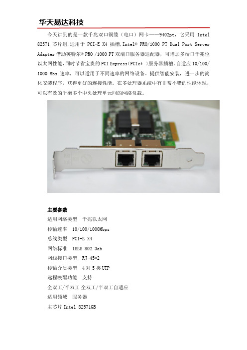
今天讲到的是一款千兆双口铜缆(电口)网卡——9402pt,它采用Intel 82571芯片组,适用于PCI-E X4插槽,Intel® PRO/1000 PT Dual Port Server Adapter借助英特尔® PRO /1000 PT双端口服务器适配器,可增加多端口千兆位以太网性能,同时节省宝贵的PCI Express(PCIe* )服务器插槽。
自适应10/100/ 1000 Mbs 速率,可以适用于不同速率的网络设备。
提供智能安装,进一步的简化安装程序,获得更好的连接性能。
在多处理器系统中有非常不错的性能体现,可以有效的平衡多个中央处理单元间的网络负载。
主要参数适用网络类型千兆以太网传输速率 10/100/1000Mbps总线类型 PCI-E X4网络标准 IEEE 802.3ab网线接口类型 RJ-45*2传输介质类型 4对5类UTP远程唤醒功能支持全双工/半双工全双工/半双工自适应适用领域服务器主芯片Intel 82571GB系统支持Microsoft Windows 2003Server,MicrosoftVista,Windows Virtual Server 2005,Red Hat Enterprise Linux* 4 or later,SUSE SLES 10 or later, Professional 9.2 or late,FreeBSD 5.x or laterIntel 9402PT支持智能安装,广泛部署,PROSet实用程序等功能。
主要用于服务器和工业相机,工控机等设备。
近年来此款千兆双口服务器网卡在机器视觉行业中地位颇高,相比普通国产网卡,Intel 9402PT能够具备更高的稳定性和安全性,是防止丢帧丢包的好选择。
更多资料参数可联系intel网卡分销中心华天易达,可提供更专业的网卡选购方案。

Intel千兆网卡PRO1000是什么意思经常有用户认为Intel PRO 1000是英特尔网卡的型号,实际上这个描述指的是Intel千兆速率的网卡,这一分类下包含很多型号,所以要如何选购一款合适千兆网卡首先要确认具体的型号。
Intel PRO 1000千兆网卡主要有5个系列:Intel PRO 1000 PT、Intel PRO 1000 MT、Intel PRO 1000PF、Intel PRO 1000 MF、Ibtel PRO1000GT用的较多的是Intel PRO1000 PT系列,尤其是IntelPRO/1000 PT Dual PortServer Adapter这款,这个描述对应的型号叫做EXPI9402PT,是英特尔一款千兆PCI-E双口网卡,对应接口类型为RJ-45,可用在PCI-E X4,X8,X16插槽上。
这款千兆双电口网卡的价格大约在八百左右是目前机器视觉和工控机行业首选的一个型号。
此外这个系列中还有一款四口千兆网卡,描述为Intel? PRO/1000 PTQuad Port Low Profile ServerAdapter,这个描述对应的型号叫做EXPI9404PTL,是Intel千兆网卡中比较早期的一款千兆四口网卡,对应接口类型同样为RJ-45,可用在PCI-E X4,X8,X16插槽上,价格大约在2千左右,在千兆PCI-E四口网卡的型号里是性价比较高的一款。
Intel PRO 1000 PF和Intel PRO 1000 MF这2个系列是千兆光纤网卡,由于成本相对较高,用的客户相对也较少,其中Intel PRO1000 PF千兆网卡是PCI-E接口的,Intel PRO 1000 MF是PCI接口的。
价格在一千五到两千五百元左右。
以上就是Intel PRO 1000千兆网卡的一些相关信,息更多技术参数和报价信息信息用户可咨询intel网卡分销中心华天易达科技有限公司,可提供更专业更合适的网卡选购方案。
ZXCTN6130设备高级硬件介绍引言本文将介绍ZXCTN6130设备的高级硬件特性。
ZXCTN6130设备是一款用于光传送网络的高性能传输设备,具有出色的可靠性和稳定性。
本文将详细介绍ZXCTN6130设备的硬件组件,包括处理器、存储器、接口等。
处理器ZXCTN6130设备搭载了一款高性能的处理器,用于处理网络流量和执行各种网络功能。
该处理器采用了先进的多核架构,能够提供出色的性能和可靠性。
处理器还支持硬件加速技术,可以实现更高效的数据处理和转发。
存储器ZXCTN6130设备内置了大容量的存储器,用于存储设备的操作系统、配置文件和其他相关数据。
存储器采用了高速闪存技术,具有快速的读写速度和可靠的数据保护功能。
同时,存储器还支持热插拔功能,方便用户在设备运行过程中进行存储器的更换和升级。
接口ZXCTN6130设备具有多种接口,用于与其他网络设备进行连接和通信。
其中包括光口、电口、管理口等接口,满足不同网络环境的需求。
这些接口支持高速数据传输和多种协议,使得ZXCTN6130设备能够与各种网络设备进行互联。
此外,接口还支持自适应技术,能够根据网络环境的变化自动调整参数,保证通信的稳定性和可靠性。
硬件安全性ZXCTN6130设备具备卓越的硬件安全性,可以有效防止未经授权的访问和攻击。
设备采用了多层次的安全机制,包括访问控制、数据加密和身份认证等技术。
同时,设备还支持硬件防火墙功能,能够实时监测和过滤网络流量,阻止潜在的攻击行为。
这些安全特性保证了ZXCTN6130设备的可靠性和稳定性。
硬件扩展性ZXCTN6130设备具有良好的硬件扩展性,可以根据用户的需求进行灵活的扩展。
设备提供了多个扩展槽位,用于安装附加模块和接口卡,以增加设备的功能和性能。
用户可以根据需要选择合适的扩展模块,如光模块、交换模块等。
这种灵活的扩展性使得ZXCTN6130设备能够适应不同网络环境的需求。
硬件可靠性ZXCTN6130设备具备高度的硬件可靠性,可以持续稳定地工作。
方正科技无线上网卡E620P用户手册(V1.0)1声明欢迎您使用方正科技无线上网卡。
在第一次安装和使用本产品之前,请您务必仔细阅读随机配送的所有资料,这会有助于您更好地使用本产品。
方正科技电脑有限公司致力于不断改进产品功能、提高服务质量,因此保留对本手册中所描述的任何产品和软件程序以及本手册的内容进行更改而不预先另行通知的权利。
本手册的用途在于帮助您正确地使用方正科技产品,并不代表2对本产品的软件配置的任何说明。
有关产品配置情况,请查阅与本产品相关合约(若有)、产品装箱单或咨询向您出售产品的销售商。
本手册中的图片仅供参考,如果有个别图片与产品的实际显示不符,请以产品实际显示为准。
3目录1产品说明 (5)2基本功能 (8)3产品介绍 (9)4驱动安装 (11)5使用说明 (12)6故障排除 (17)7维护保养指南 (25)41产品说明1.1产品总体特点:1、遵循中国EDGE标准;2、产品性能稳定、持续上网时间长、不掉线;3、天线灵敏度高、接受信号能力强、拨号速度快;4、低发热、良好散热设计给产品稳定运行提供保障;5、知名品牌,性价比高,技术先进、款式时尚、引领无线上网卡潮流;56、符合国家电子产品技术指标要求;7、机器检测挑卡、合格率达99%以上;8、产品兼容性好,是市面上对笔记本兼容性最强的网卡之一;9、软件功能强,自动拨号,支持VISTA系统;10、支持热拔插,可随时安装或取下上网卡,无需重启操作系统;11、提供品牌服务承诺,三个月内属产品质量问题保证升级与更换。
1.2技术规格:多信道:EDGE的最高传输速度可达384Kbps,实际上网速度相当于准3G速度。
6多频段:EDGE使用850/900/1800/1900Mhz四频段,可以提供更好的空间覆盖和深度覆盖,资源使用更优。
1.3操作简单功能丰富快速安装:对于各类计算机,附带的应用软件组件可以帮助您快速安装、配置和管理无线上网卡。
系统支持:其设计和应用软件可轻易支Windows2000/XP/VISTA(中、英文)等常见的操作系统,满足不同用户的要求。
Intel类别的网卡在各大网络设备和项目中的使用频率是可以说是比较高的,近几年随着机器视觉行业的高速发展,Intel网卡在这个行业领域开始占据不少市场份额。
从事机器视觉行业的客户起初选择网卡也选择过一些价格便宜的国产网卡,但是根据众多机器视觉用户的检验以及长期实践发现Intel网卡才是机器视觉行业好伙伴。
机器视觉行业为什么优先选择Intel网卡?一、更具稳定性英特尔公司的IT产品价格相对普通产品是要高一些的,但是这也是因为英特尔公司在研发产品以及设计产品中耗费了大量人力技术,使得生产出来的网卡更具稳定性。
二、更具可靠性用过便宜网卡的机器视觉用户应该遇到过丢包丢帧的情况,这种情况给用户带来很大的困扰,而经常这种情况下换上英特尔网卡则能够解决问题,确保工业相机可以正常的使用,形成一个良性的使用过程。
三、更具保障性性原厂原装的Intel网卡是有终身免费质保服务的,这也很大程度上让机器视觉用户觉得安心,一个完善的售后体制能够保障后期的服务。
机器视觉行业常用的网卡型号机器视觉行业普遍把Intel网卡用在工业相机上,其中GIGE相机常用到千兆网卡。
千兆单口网卡930CT或者9400PT9301CT是一款台式机网卡,一些考虑预算的机器视觉用户会选择这款网卡,不过少数性能要求高的工业相机是需要用服务器网卡,因为9301CT的定位就是台式机网卡。
所以其实综合来说建议单口用服务器网卡9400PT千兆双口网卡9402PT或者I350-T29402PT是这几年机器视觉行业应用最多的一款网卡型号,大多数工业相机双端口网卡都是用这款,少数客户遇到主板不兼容的情况会换型号I350-T2Intel千兆四口网卡EXPI9404PTL或者I350-T4V2四口千兆网卡性价比高的则选择EPXI9404PTL,对性能要求更高的可以尝试新款I350-T4V2.以上就是机器视觉工业相机常用的几款Intel网卡,客户可以根据自己的需求来选择端口数量,更多千兆网卡的详细内容可联系Intel网卡分销中心华天易达为您提供更满意的选购方案。
BL-P6130 千兆以太网网卡
简要描述
符合IEEE802.3、IEEE802.3u、IEEE802.3ab以太网标准;
支持10Mbps、100Mbps、1000Mbps三种传输速率,10/100M全双工/半双工模式,1000M全双工模式;低电磁干扰线路驱动器,具有强大的CESD性能;
支持平行/交叉线自动识别(AutoMDI/MDIX)功能,简化网络的架设、维护工作;
支持NWAY自动协商功能,自动侦测传输速率及工作模式,自动选择减少烦锁的一系列;
具有先进的故障报告功能;
支持IEEE802.3x全双工的流量控制;
集成芯片,高性能应用程序发送和接收遵循先进先出法则;
支持千兆超长帧的发送和接收;
高达2000M的吞吐量;
高级配置与电源接口(ACPI);
内置线性核定功率调节器,简化电路板上的功率分配;
系统支持:Windows 98/Me/2000/2003 Server/XP/Win7/Mac/NetWare Server/Linux/Win CE操作系统产品规格
图片展示。