SUPEX 产品介绍
- 格式:pdf
- 大小:2.44 MB
- 文档页数:33
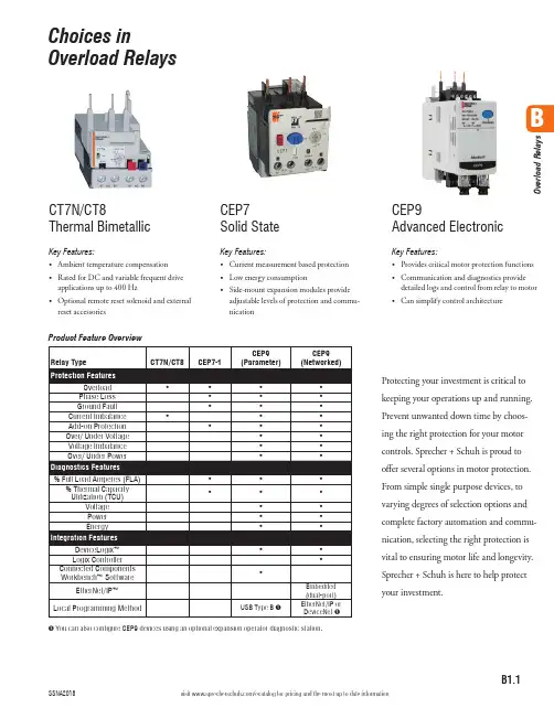
B1.1visit /ecatalog for pricing and the most up to date informationBO v e r l o a d R e l a y sProduct Feature Overview➊ You can also configure CEP9 devices using an optional expansion operator diagnostic station.Choices inOverload RelaysProtecting your investment is critical to keeping your operations up and running. Prevent unwanted down time by choos-ing the right protection for your motor controls. Sprecher + Schuh is proud to offer several options in motor protection. From simple single purpose devices, to varying degrees of selection options and complete factory automation and commu-nication, selecting the right protection is vital to ensuring motor life and longevity. Sprecher + Schuh is here to help protectyour investment.CT7N/CT8Thermal BimetallicKey Features:• Ambient temperature compensation • Rated for DC and variable frequent drive applications up to 400 Hz • Optional remote reset solenoid and external reset accessoriesCEP7 Solid StateKey Features:• Current measurement based protection • Low energy consumption• Side-mount expansion modules provide adjustable levels of protection and commu-nicationCEP9Advanced ElectronicKey Features:• Provides critical motor protection functions • Communication and diagnostics provide detailed logs and control from relay to motor • Can simplify control architecture3r d G e n C E P 7 O v e r l o a d sB1.2visit /ecatalog for pricing and the most up to date informationCEP7 Solid State Overload RelaysThe Third GenerationAdvanced solid state motor protectionThe CEP7-1__ relay provides the follow-ing features:• Electronic overload detection • Simple configuration • Selectable trip class • Adjustable trip current• Integration with CA7/CAN7 contactors• Test and reset buttons• Auto (CEP7-1EF only)/manual resetselection• RMS current sensing (50/60 Hz)• External current transformer configu-rations • Single- and Three-phase compatibility within the same unit • Direct and pass-through mounting options The CEP7-1__ relay lets you connectaccessory modules, some of which inter-face through the front-mounted com-munication port. Accessories include:• Ground fault/jam protection module(CEP7-1EF only)• Remote reset solenoid• Anti-tamper shield• Electronic remote indication display CEP7–ERID, with or without reset (CEP7–1EF units only)• External reset adapter • DIN rail/Panel adapterOverload Performance• Current Measurement-based Protection Current measurement-based overload protection more accurately models amotor’s thermal condition. Ambient temperature over the specified temperature operating range does notimpact the performance of current measurement-based designs.• Electronic Design Thermal model-ing is performed electronically withprecision solid-state components, us-ing a state-of-the-art microprocessor.The microprocessor continually pro-cesses motor current data to accurately maintain the time-current status of the motor thermal capacity utilization (%TCU) value.• Thermal Memory A thermal mem-ory design lets the CEP7-1 OverloadRelay model the heating and cooling effects of motor on and off periods. This achieves accurate protection for both hot and cold operation.• Phase Loss Protection Phase loss detection is incorporated into the CEP7-1 Overload Relay, allowing it to respond quickly to this type ofcondition.Direct Mount Mechanicalattachment800A100A 100A 100A3r d G e n C E P 7 O v e r l o a d sB1.3visit /ecatalog for pricing and the most up to date informationVersatile and Expandable• Adjustable Trip Class and Reset Modes The Basic CEP7-1EE relay of-fers Trip Class 10 and 20 with manual reset only. The Advanced CEP7-1EF relay offers Trip Class 10, 15, 20, and 30 with a selectable dial, in manual or automatic reset.• Pass-through Design The CEP7-1 relay Pass-through option consumes less panel space than a standard CEP7-1 relay that is configured with a panel-mount adapter. The pass-through design provides integrated DIN Rail mount and panel mount-ing holes. The CEP7-1 Pass-through Electronic Overload Relay provides the same protection and expandable accessory capabilities as a standard CEP7-1 relay.• External CTs For motor overload protection applications above 100A in current sensing capability, the CEP7–1EF_Z relay offers functionality with external CT configurations up to 800A maximum capacity.Wide current adjustment rangeThermal or bimetallic overload relays typically have a small current adjust-ment range of 1.5:1 meaning that the maximum setting is generally 1.5 times the lower setting. Sprecher + Schuh’s CEP7-1 overload relay is capable of adjustment to a maximum of five times the minimum set current, which dra-matically reduces the number of units required on-hand to cover the full range of current settings up to 100 amperes.Selectable tripping classBoth the CEP7-1 models have standard Class 10 tripping characteristics. The CEP7-1EE Basic model is equipped with dip switches that allow the select ability between Class 10 and Class 20, while the CEP7-1EF Advanced model possesses a selection dial on the face of the overload for trip classes 10/15/20 and 30. This selection feature allows you to closely match the Trip Class with the start-up time of the motor.Adaptive ProtectionRemote Reset CapabilityThe CEP7-1EF relay offers optional remote reset capabilities through the use of an electro-mechanical reset solenoid or an electronic remote reset accessory module.Ground Fault and Jam Protection The CEP7-1EF relay offers optional ground fault and jam protectionthrough the use of an accessory module. The ground fault current detection level is configurable via a mechanical rotary dial from 0.02…5A. Jam protection is configurable via two mechanical rotary dials, current level from 125…600% FLA, and delay from 0.1…10 seconds.Robust designThe CEP7 has been designed to physi-cally extend to the back-pan therefore aligning the mounting of the overload with the corresponding contactor. Further, the mechanical attachment and direct electrical connection to the contactor provides a robust mounting, which means less damage from shipping or during field wire installation. The bipolar latching relay which controls the normally closed trip contacts and nor-mally open alarm circuit contacts have been self-enclosed, therefore insulating the electromagnet and shielding against airborne metal particles and other po-tential environmental debris. The CEP7 has been tested to operate in -20° C. or up to 60° C (140 °F.) and withstand 3G of vibration or 30G of shock on a mountain up to an altitude of 2000m or in a jungle at 95% humidity. Reliability under every conceivable environmen-tal condition is a quality built into the design of the CEP7 electronic overload relay.Increased accuracy and improved motor protectionMicroelectronics provide flexible and ac-curate motor overload protection. Unlike traditional overload relays that simulate heat build-up in the motor by passing current through a heater element, CEP7 solid state overload relays measure motor current directly through integrated cur-rent transformers. The transformers, in turn, create a magnetic field that induces DC voltage onto the ASIC board. The electronics identify excessive current or loss of phase more accurately, and react to the condition with greater speed and reliability than traditional overload re-lays. In addition, CEP7 solid state relays offer setting accuracies from 2.5 – 5% and repeat accuracy of 1%.Dramatically lowered energy requirement saves money, reduces panel spaceBecause traditional overload relays work on the principle of “modeling” the heat generated in the motor (recreating the heat in the bimetal elements or heaters), a significant amount of energy is wasted. In traditional bimetallic overload relays, as many as six watts of heat are dissipat-ed to perform the protective function. Because the CEP7 uses sampling tech-niques to actually measure the current flowing in the circuit, very little heat is dissipated in the device…as little as 0.5 watts. This not only reduces the total amount of electrical energy consumed in an application, but it can also have a dra-matic impact on the design and layout of control panels. The density of motor starters can be much greater because less heat is generated by each of the individ-ual components. Higher density results in smaller control panels. In addition, special ventilation or air conditioning that might have been required to protect sensitive electronic equipment such as PLC’s can now be reduced or eliminat-ed. CEP7 overload relays dramatically reduced energy requirement saves moneyand reduces panel space.CEP7-1EF Selectable Dial for • Manual vs. automatic• Trip class 10, 15, 20 or 30)CEP7-1EE SwitchSelection for Trip class (10 or 20)3r d G e n C E P 7 O v e r l o a d sB1.4visit /ecatalog for pricing and the most up to date information➊ This reference is not intended to be a guide for selecting contactors. Size overload relays using the full load current of the motor.➋ The reset time of a CEP7 set in the automatic mode is approximately 120 seconds.➌ CEP7 overload relays do not work with Variable Frequency Drives, DC Applications or Softstarters with braking options.shown: CEP7-1EFGPCEP7-1EF Automatic or Manual Reset for 1Ø and 3Ø Applications shown: CEP7-1EFLZDescriptionFig. 1 - The Pass-Thru version of the CEP7 permits separate mounting of the overload relay.Fig. 2 - Motor load side cables simply pass-thru a window in the overload relay body. The internal current transformers monitor the current flow.Benefits• N o need for a panel mount adapter as required with direct-connect versions • E liminates 3 to 6 wire terminations• D esigned for use with CA8 or CA7 contactors • E asily replaces outdated overload relays in existing starter assemblies• P rovides state-of-the-art accuracy and motor protectionFig. 2B3r d G e n C E P 7 O v e r l o a d sB1.5visit /ecatalog for pricing and the most up to date informationAccessories - CEP7-1CEP7-1EPB CEP7-1EPD CEP7-1EPE➊ ATTENTION: The CEP7 Overload relay is not a ground fault circuit interrupter for personnel protection as defined in Article 100 of the NEC.➋ Dynamic inhibit: Protective function is enabled after the motor current goes above 150% and then falls below 125%➌ Utilizes UL or CE approved Current Transformers in conjunction with an overload selection – which is commonly selected as a CEP7-1EF_Z version. In the instance that a CEP7-1E_C_ overload is used, there is a reference table on catalog page B1.9 to assist with current setting guidance.3r d G e n C E P 7 O v e r l o a d sB1.6visit /ecatalog for pricing and the most up to date informationCEP7 Ground Fault Sensor SelectionGround fault current is sensed by passing all lines carrying current to and from a motor through the window of a special current transformer called a ground fault sensor. If all the current to the motor returns through the lines in the sensor window, no significant current will be induced in the sensor secondary. If, however, ground fault current returns via a path external to the sensor, such as via the conduit walls, a current will be induced in the sensor secondary. This current will be sensed and amplified by solid state circuits. If the ground fault current is larger than the selected ground fault trip level of the overload relay, the overload relay will trip.➊ For a three phase system with one cable per phase.➋ For a three phase system with two cables per phase.CEP7-1 Ground Fault Sensor InstallationGround Fault Sensor Control WiringMotorL2L3L1GroundFault SensorBCEP7Overloadsvisit /ecatalog for pricing and the most up to date informationT2T31314A1A2659798Specifications - CEP7 Electronic Overload RelayThis section contains specifications, wiring diagrams, andcertification information for the CEP7 Electronic OverloadWiring DiagramsThe figures in this section illustrate various wiringconfigurations for the CEP7 Electronic Overload Relay and95T2T3T19697Connection must beShort-circuit Protection Deviceonnection must be tted by the userShort-circuit Protection Device Transformer Overload Relay Application and Installation Instructions, publication193-IN084.Current TrShort-circuiProtection DT1/2For more inBulletin 19InstructionTransforme193-IN0843r d G e n C E P 7 O v e r l o a d sB1.8visit /ecatalog for pricing and the most up to date informationAttributeRatingCEP7-1EE..CEP7-1EF..Type of Relay Ambient Compensated Time-DelayPhase Loss SensitiveNature of Relay Solid-state FLA Setting Rotary Dial Trip Rating 120% FLATrip Class 10, 2010, 15, 20, 30Reset ModeManualAutomatic or ManualOverload ResetLevelAuto Reset occurs at 70% TCU when accessory powered, after 2 minutes when self powered.Manual Reset can occur anytime by pressing themanual reset button. Electronic Reset (ERID input)can only occur below 70% TCU.* Typical reset time for CEP7-1EF devices set to automatic reset mode is dependent upon overload trip class. Typical reset time for Trip Class 10 is 90 seconds, Trip Class 15 is 135 seconds, Trip Class 20 is 180 seconds, and Trip Class 30 is 270 seconds.Ground Fault ProtectionAttribute Rating CEP7-1EF Type Core Balanced Intended Use Equipment Protection Classification (Per UL 1053)Evaluated to UL 1053 but notlisted as such Internal Protection Range 0.02…5.0 ATrip and Warning Time DelayFixed at 100 msec ± 20 msecControl Relay RatingsRelay N.O./N.C.Type of ContactsAg/NiRated Thermal Current (I the )B600: 5.0 A; C600: 2.5 A; R300: 1.0 AContact Reliability[V]17 V, 5 mA Rated Insulation Voltage - (U I )[V]690V ACRated Operation Voltage - (U e )[V]690 AC (IEC) / 600 AC (UL/CSA)Rated Operating Current (I e )[V]B600: 3 A (@120V AC), 1.5 A (@240V AC)[V]C600: 1.5 A (@120V AC), 0.75 A (@240V AC)[V]R300: 0.22 A (@125V DC), 0.11 A (@250V DC)Minimum Operating Current [V]10 mA @ 5V DCRating Designation N.O. C600 / N.C. B600 (AC)N.O. / N.C. R300 (DC)Utilization Category AC-15/DC-13B600 VA Rating 3,600VA make / 360VA break C600 VA Rating 1,800VA make / 180VA break R300 VA Rating28VA make / 28VA breakRated Number of Mechanical OperationsRelay N.O./N.C.10,000W/ CA7-9…CA7-3713,000,000W/ CA7-43…CA7-5512,000,000W/ CA7-60…CA7-976,000,000Motor/Load RatingsTerminals1/L1, 3/L2, 5/L3, 2/T1, 4/T2, 6/T3Terminal Style Devices Rated Insulation Voltage - (U i )[V]690V AC Rated Operating Voltage - (U e ) IEC [V]690V AC Rated Operating Voltage - (U e ) UL [V]600V ACPass-thru Style Devices Rated Insulation Voltage - (U i )[V]1000V AC Rated Operating Voltage - (U e ) IEC [V]1000V AC Rated Operating Voltage - UL/CSA [V]600V AC Rated Impulse Voltage - (U imp )[kV]6 kV ACRated Operating Current - (I e )See product selection tableRated Frequency[Hz]45 (65)➊For multiple conductor applications, the same size and style wire must be used.Table for using Current Transformers with CEP7-1E_C_ (range 1.0…5.0 amps) overload relay3r d G e n C E P 7 O v e r l o a d sB1.9visit /ecatalog for pricing and the most up to date informationTechnical InformationEnvironmental RatingsOverload Rating Accessory RatingAmbient TemperatureStorage [˚C]-40...+85 (-40...+185 ˚F)Damp Heat - Steady State(per IEC 60068-2-78)93% R.H., 40 °C (104 °F), 56 days Damp Heat - Cyclic (per IEC 60068-2-30)93% R.H., 25 °C/40 °C (77 °F/104 °F), 21 CyclesCooling MethodNatural convection Vibration (per IEC 68-2-6), operating [G]3Shock (per IEC 68-2-27), operating [G]30Maximum Altitude [m]2000Pollution Environment Pollution Degree 3Degree of ProtectionIP20 (front of panel)IP20Electromagnetic Compatibility Immunity and EmissionsOverload RatingAccessory RatingElectrostatic Discharge Immunity IEC 61000-4-2, IEC 60533 6 kV Contact Discharge, 8kV Air Discharge(Performance Criterion “B”)8 kV Contact Discharge, 8kV Air Discharge(Performance Criterion “B”)Radio Frequency Immunity IEC 61000-4-3[Hz]10V/m; 80 MHz...1.0 GHz [Hz]3V/m; 1.4 GHz...2.0 GHz [Hz]1V/m; 2.0 GHz...2.7 GHzIEC 60533[Hz]10V/m; 80 MHz...2.0 GHz (Performance Criterion “A”)Electrical Fast Transient / Burst Immunity IEC 61000-4-4, IEC 60533[V]4kV (3-phase Power); 2kV(Control Power & Communication I/O when CEP7-1ERR or CEP7-1EGJ accessory installed); Performance Criterion “A”Surge ImmunityIEC 61000-4-4, IEC 60533[V]2kV (L-N); 1kV (L-L); Performance Criterion “B”Radiated Emissions CISPR11 Environment A [Hz]30 MHz…1.0 GHz IEC 60533[Hz]150KHz…2.0GHzConducted Emissions CISPR11 Environment A [Hz]150 KHz…30 MHzIEC 60533[Hz]10 KHz…30 MHz (General Power Distribution Only)Conducted ImmunityIEC 61000-4-6, IEC 60533[Hz]Modulation 80% AM at 1 KHz; 10V RMS (150 KHz…80 MHz)Power Frequency Magnetic Field Immunity IEC 60947-1, IEC 61000-4-8[Hz]30 A/m; 50 HzVoltage Variation Immunity IEC 61000-4-11, IEC 60533[V]—Control Power 40…240V (AC/DC)Wiring SpecificationsWiring Specifications for CEP7-1E__B, CEP7-1E__D, and CEP7-1E__EControl WiringPower Wiring AllCEP7-1E BCEP7-1E DCEP7-1E EWire TypeWires Range Torque Range Torque Range Torque Range Torque Flexible Stranded w/ Ferrule1 Wire 0.75…2.5 mm 21.4 N•m2.5…16 mm 2 2.5 N•m 2.5…16 mm 2 2.5 N•m 4…35 mm 2 4.6 N•m2 Wires ➊ 2.5…10 mm 2 3.4 N•m 2.5…10 mm 2 3.6 N•m 4…25 mm 2Stranded / Solid1 Wire0.75…4.0 mm 2(18…12 AWG)1.4 N•m (12 lb•in)2.5…16 mm 2(14…6 AWG) 2.5 N•m (22 lb•in) 2.5…16 mm 2(14…6 AWG) 2.5 N•m (22 lb•in)4…35 mm 2(12…1 AWG) 4.6 N•m (40 lb•in)25 mm 2(4 AWG) 3.4 N•m (30 lb•in)25 mm 2(4 AWG) 3.4 N•m (30 lb•in)2 Wires ➊2.5…16 mm 2(14…6 AWG)2.5…16 mm 2(14…6 AWG)3.6 N•m (32 lb•in)4…35 mm 2(12…2 AWG)3r d G e n C E P 7 O v e r l o a d sB1.10visit /ecatalog for pricing and the most up to date informationTechnical InformationOverload Trip CurvesTypical reset time for CEP7-1EF devices set to automatic reset mode is dependent upon overload trip class. Typical reset time for Trip Class 10 is 90 seconds, Trip Class 15is 135 seconds, Trip Class 20 is 180 seconds, and Trip Class 30 is 270 seconds.Class 30Class 20Class 15Class 10B3r d G e n C E P 7 O v e r l o a d sB1.113r d G e n C E P 7 O v e r l o a d sB1.12B3r d G e n C E P 7 O v e r l o a d sB1.13B3r d G e n C E P 7 O v e r l o a d sB1.15➊ Terminals R1 and R2 are used with CEP7-ERID and CEP7-1ERIDN modules.➋ External power must be user supplied. 24…240V, 47…63 Hz or DC.➌ Connect current sensor to Terminal S1 and S2Expansion Accessory Ratings CEP7-1EGJ/1ERRAttributeRatingRated Insulation Voltage Ui 264V (AC/DC)Rated Operating Voltage Ue, IEC24...240V (AC/DC)Rated Frequency 45...65 HzPower Consumption0.8 Watts at 24V AC; 1.0 Watts at 240V AC➍ Terminals R1 and R2 are used with CEP7-ERID and CEP7-1ERIDN modules.➎ External power must be user supplied. 24…240V, 47…63 Hz or DC.。

SUPPLEX®系列织物功能介绍INVISTA SUPPLEX纤维的优点:透气快干、耐磨、不易折皱变形、抗紫外线、具棉质感的柔软舒适、不褪色、轻盈好打理高科技物料必定要提到DuPont <杜邦公司>,1938年渥那斯、卡诺莎尔博士为杜邦发明了尼龙。
尼龙所具有的巨大的强度重量比在各种用途上都创造了直接价值,无论是用于降落伞还是女士的丝袜。
在全球尼龙长短纤产能排名上,美国杜邦公司以年产80.6万公吨之规模高居世界龙头。
SUPPLEX®面料是英威达(原杜邦)公司特别开发的,集合了棉制品的柔软、顺滑触感和尼龙的高强度和耐久性于一体的纤维;并为全球知名户外服装品牌所推崇。
英威达INVISTA的SUPPLEX®系列产品的特色及功能SUPPLEX®面料是以空气喷射变形处理过的纤维,可提供消费者拥有棉感和先进纤维的技术。
世界各处的消费者都喜欢棉质感的布料和它的自然美学,将其应用在其许多服装类别的选择。
但是棉花有其缺点:皱折、缩率及颜色褪色问题,因此英威达的科学家开发了SUPPLEX 布料,提高自然感和结合棉花的传统优势,成为现代新纤维的技术。
产品功能˙柔韧、轻质,而且比标准尼龙软26%-36%,具棉质感。
又同时兼具尼龙的平顺与耐用。
˙不起皱,不缩水,而且不褪色。
衣物经过太阳照晒、雨淋和反复洗涤、晾干后将会很好保持原型,而且颜色依旧艳丽。
˙耐磨、抗擦伤、抗撕裂。
˙吸湿快干,具良好的透气性。
夏天穿着不闷热。
˙抗紫外线。
SUPPLEX®系列织物,为永久性的机能性尼龙纤维,并不会因洗涤次数而尚失功能性。
SUPPLEX®系列衣物建议洗涤方式:采一般水温(约30度)可机洗,自然风干即可。


美国SPEX公司各类光谱仪器介绍
佚名
【期刊名称】《现代科学仪器》
【年(卷),期】1992(000)003
【总页数】2页(P48-49)
【正文语种】中文
【中图分类】TH744.1
【相关文献】
1.美国硼砂集团公司产品速乐硼、持力硼、众爱硼介绍——昆明美硼贸易有限公司总经销 [J],
2.美国BIO—RAD(伯乐)公司最新付里叶红外光谱仪器介绍—FTS175/FTS185 [J], 何林涛
3.美国伯乐公司及其产品介绍二:傅里叶变换红外光谱仪介绍 [J], 无
4.美国DSI公司推出适用于光谱仪器的红外窄带通滤光片 [J], 岳桢干
5.美国两家小型咨询服务公司——技术转让公司与FTI—CHINA技术服务公司介绍 [J], 王振荃
因版权原因,仅展示原文概要,查看原文内容请购买。

Wavecom Fastrack Supreme 20 GPRS/EDGE Modem产品简介一、概览Wavecom Wireless Fastrack Supreme 20 是Wavecom 集大成产品,是Wavecom公司20年的巅峰之作。
Supreme 20是一款即插即用型EDGE/GPRS/GSM Modem,可以快速将您的应用连接到移动网络。
这款产品最大的特点就是通过扩展板实现IO、USB、GPS、Ethernet等功能,您还可以开发自己的扩展板。
Fastrack Supreme 20 支持850/900/1800/1900MHz,支持GSM,SMS,CSD,GPRS,EDGE FR/HR/EFR/AMR,通过内嵌的Internet软件,可以支持TCP/UDP/FTP/HTTP/Email等协议。
Wavecom Fastrack Supreme 20 支持Class 10 EDGE。
每个Fastrack Supreme 使用Wavecom Q26-系列Wireless CPU,一款强劲的ARM9 32位26-104MHz处理器。
通过Wavecom 的OPEN AT 嵌入式开发环境,客户可以自行开发M2M应用。
Wavecom厂家提供如下三种扩展板:▪USB + IO Expansion card.▪USB + C-GPS Expansion card.▪USB + C-GPS + IO Expansion card.二、主要优点●ARM9, 32 bit, 104 MHz,Open AT® RTOS●4频段EDGE/GSM/GPRS (850/900/1800/1900)●内嵌Internet (WIPsoft)●可选择多种扩展板: I/O, USB, GPS, Ethernet, Zigbee, Wavenis etc.●AT&T认证,适用于美国市场三、产品规格●频段:(MHz) 4频段GSM: 850/900/1800/1900 MHz●处理器:ARM946/DSP, 32 bit, 26-104 MHz●存储:内部64Mb Flash 和32Mb PSRAM●输入/输出:2 GPIOs (可通过扩展板增加IO )●通讯接口:1 串口UART (可通过扩展板增加) 通过扩展板IESM 支持USB 2.0 ●语音接口:1 路语音●数据:GSM standard, SMS, CSD, GPRS class 10●语音编码:Quad codec (FR/HR/EFR/AMR)●RF 天线:SMA母头●系统IO 连接:DB15 HD●供电:5V - 32V VDC●通过认证:FCC PTCRB GCF C-Tick CE●工作环境温度:-30°C+75°C Class A -40°C+85°C Storage●尺寸/Size:L 73 x W 54.5 x H 25.5mm四、相关配件1.220V AC 到12V DC 电源适配器220V AC 到12V DC 电源适配器2.DB9 到DB15HD 带语音的串口数据线∙DB9 连接电脑主机∙DB15HD 连接Fastrack Supreme ∙RJ11 连接电话听筒3.SMA天线双频900/1800MHz GSM SMA天线4.Wavecom GPS + USB IESM 扩展板∙GPS with Aidding Capability∙USB 2.05.Wavecom IO + USB IESM 扩展板Wavecom IO + USB IESM扩展板提供:∙USB 2.0∙Provides upto 5 Additional IO for Fastrack Supreme Modems ∙ 1 UART, 1 ADC, 1 DAC, 1 SPI, 1 I2CWavecom IO + USB + GPS IESM 扩展板提供:∙Up to 16 I/O∙On-board GPS∙USB connectivity∙Write own GPS and IO application in OpenAT and host on modem 五、Supreme 20的安装六、扩展板的安装更多产品信息,请访问: 。

SUPRAREX SXE.Better than ever. Versatile as never before.M O R E P E R F O R M A N C E.M O R E P R O D U C T I V I T Y. M O R E P R O G R E S S I N C U T T I N G.Earth moving machinery for example. Or state-of-the-art shipbuilding technology. Even steel bridges or in plant and mechanicalengineering: ESAB is always there. Withprofessional solutions for welding andcutting, thus makes us number one in many industries worldwide. Our sector-specific experience and all of our technical skill are now combined in the SUPRAREX SXE to form a machinery concept with an unbeatable variety of profitable applications.The SUPRAREX SXE.Your productive interfacein the manufacturing process.from ESAB it is perfectly equipped for the integrated, automated production process.Every detail of the SUPRAREX SXE satisfies even the most stringent quality requirements, whilst the extremely low maintenance costs and long service life make for a surprisingly favorable cost-benefit analysis. Trust in the power of evolution, invest for the bestSUPRAREX of all time.SUPRAREX SXE. The evolution.How good gets even better.Pure dynamism, power right down the line.The new SUPRAREX generation convin-ces users with impressive accelerationand deceleration values helping you toachieve even more productivity and preci-sion. As a high-performance, heavy-duty gantry machine with a rail span of 3,000 to 8,500 mm, the SUPRAREX SXE thus forms the solid foundation for economical cutting and marking with plasma and oxyfuel. What’s more, with a VISION control system and COLUMBUS programming softwareWhich metals and what plate size need to be processed? ESAB gives you the right answers to these and many other questions with the SUPRAREX SXE!The users and their requirements are the measure of all things here; the cutting technology adapts itself harmoniously, grows with the user demands and isalways easy to update.The SUPRAREX SXE.A concept that adapts itself.Freedom is the basic requirement for theexpansion of your productivity. Flexibility isthe key to sustainable process integration.With the innovative, modular SUPRAREX SXEgantry machine system, you have complete freedom to configure the perfect solution of your individual application.Which cutting technology do you want to work with? How many cutting tools would you like to use and combine?about the ease and safety of use of your cutting line as well as loading and unloading. For example, the special track concept allows rapid, trouble-free material feed inthe whole cutting area.That is also an effective way to help save valuable time and increase your operatingefficiency.Flexibility and versatile capability at a high level.With the SUPRAREX SXE, the options forcombining the diverse range of systemmodules are almost limitless. From thecutting table and the power supply all theway to the peripheral environmental techno-logy: everything comes from ESAB, everything works together optimally, everything satisfies our internationally recognized high quality level. Of course at the same time we have also thoughtPlasma cutting and marking withthe same torch Left: Powder marking right: Compressed air markingLabeling and marking with InkJet High-precision plasma cuttingFit for all processes. With plasma,oxyfuel and combined.The SUPRAREX SXE is ready to receive amultitude of different tools for cutting, weldpreparation and marking with advancedplasma technology or tried and tested oxfuel cutting. Even combinations of these processes or plasma cutting and marking without changing tools is easily achieved with the SUPRAREX SXE.The SUPRAREX SXE from ESAB:everything for your success.Even for accurate bevel cutsPlasma bevel cutting with the VBA ExpertOxyfuel cutting up to 200 mm material thicknessOxyfuel bevel cutting with VBA-IR Grid cutting with oxyfuelESAB. Your partnerin welding and cutting.Seven decades of experience and the consistent focuson the needs of our customers are the foundations for thesuccessful and comprehensive product range of our cuttingmachines. In keeping with the thermal cutting processes– plasma cutting, oxyfuel cutting and laser cutting –ESAB has developed a range of machines that efficientlycombine the highest cut quality with high cutting speeds,allowing intelligent integration into automated productionprocesses. So in many sectors, the SUPRAREX SXEmachine series also helps to optimize production andincrease the operating efficiency of our customers.ESAB CUTTING SYSTEMS GmbHRobert-Bosch-Str. 20 · D-61184 Karben, GermanyTel.: +49(0) 60 39 / 40-0 · Fax: +49(0) 60 39 / 40-301E-Mail:*********************Includes manufacturing facilities of ESAB North America,a wholly owned subsidiary of Anderson Group Inc.Reg.no.SUPRAREX_EN_27_1·Technicalmodificationsanderrorsexcepted.。


SX-DS-158, SX-DS-208, SX-DS-1011i, SX-DS-1611iUser Manual© 2018 AMETEK Electronic Systems Protection | Technical Support 1-800-645-9712 | UM-Defender-Rack-Rev-AI. Product OverviewThe SurgeX Defender Series are AC surge suppressors and power filters designed to be installed in a 19-inch/48.26 cm equipment rack. 120V and 240V models are available to match global power requirements.Model Voltage Current Input Plug Output ReceptaclesSX-DS-158 120 V 15A NEMA 5-15P 8, NEMA 5-15RSX-DS-208 120 V 20A NEMA 5-20P 2, NEMA 5-20R6, NEMA 5-15RSX-DS-1011i 240 V 10A IEC C14 11, IEC C13SX-DS-1611i 240 V 16A IEC C20 11, IEC C13II. InstallationThe Defender Series are designed to be installed in a 19-inch/48.26 cm equipment rack and require one unit (1-U) of rack space. Use the four screws provided with the product to secure the rack ears to the rack rails. These screws can be tightened by hand and do not require tools.120V Models (SX-DS-158, SX-DS-208): Connect power to the unit by plugging the attached power cord into a properly wired and grounded supply receptacle.240V Models (SX-DS-1011, SX-DS-1611i): Connect power to the unit by plugging an appropriately rated 3 wire grounding type power cord into a properly wired and grounded supply receptacle. The socket-outlet shall be installed near the equipment and shall be easily accessible.Do not plug the unit into a relocatable power tap.The maximum current rating of each individual receptacle, and of the unit as a whole, must not be exceeded: Model Total Maximum Current Maximum Current Per OutletSX-DS-158 15 A 15 ASX-DS-208 20 A 6 Outlets, 15A2 Outlets, 20ASX-DS-1011i 10 A 10ASX-DS-1611i 16 A 10APlug the equipment cords into the receptacles as needed.III. IndicatorsLocated on the front panel is a green System On LED.All models: When the System On LED is illuminated, there is AC power at the AC mains input to the product, and at each of the product’s outlets.SX-DS-158, SX-DS-208: When the System On LED is not illuminated, one of the following conditions is true: •There is no power at AC mains input, or•The supply receptacle is mis-wired, with the Line and Neutral conductors reversed, or•The supply voltage is too high (> 180V ± 10V), or•The input circuit breaker has tripped.SX-DS-1011i, SX-DS-1611i: When the System On LED is not illuminated, one of the following conditions is true: •There is no power at AC mains input, or•The input circuit breaker has tripped. IV. Specifications。

SuperJet.S.Eutalloy ®Nuevas mejoras de diseño que suponen:Flujos de gases y polvo optimizados a través de los circuitos internos del soplete. Incremento de la tasa de proyección en grandes piezas o de fuertes espesores. Mayor control de pequeños depósitos en esquinas y bordes finos.ReduzierterSobreproyección de polvo minimizada y sus costes de eliminación.Prolongación de la vida en servicio de las piezas e incrementode la productividad industrial.Soplete para realizar recubrimientos antidesgastecon las aleaciones en polvo EUTALLOY®Con el proceso Eutalloy se aplican recubrimientos deprotección en piezas de máquinas industriales sometidasa desgaste, prolongando su rendimiento en servicio. Se pue-den proyectar una amplia gama de aleaciones que se funden yunen metalúrgicamente al sustrato utilizando la última tecnologíade proyección SuperJet S. Aprobaciones independientes y extensivosensayos de campo aseguran un nuevo standard de calidad en los camposdel mantenimiento preventivo y aplicaciones de reparación.Sistema Modular, Multi-Propósito.SuperJet-S- Eutalloy es un soplete de proyección que puede ser fácilmente adap-tadopara realizar recubrimientos de superficies, reparación de superficies metáli-cas planas bordes de precisión ó piezas de rotación. Propiedades únicas del sopletemodular SuperJet-S :•Ensamblaje manual rápido de la lanzacon rota ción para soldadura toda posición.•Gama completa de lanzas, cada una con su inyector y mezclador para asegurar unaóptima alimentación de polvo para cada ajuste de llama.•Canal interno de polvo y boquillas diseñados para una máxima resistenciaaldesgaste y fiabilidad.•Todos los elementos del soplete son fácilmente accesiblespara su limpieza o reemplazamiento.•Cierre rápido para unrápido reencendido de una llamaajustada sin la necesidad de actuar sobre lasválvulas.•Diseño ergonómico para un fácil y ligero manejo. Escudo térmico deprotección orientable.Diseño Exclusivo con Mejoras de Calidad:El cuerpo de sopleteT ecnología CNC de mecanizado de precisión para asegurar unasalineación y trayectoria perfectas del paso de gases en el cuerpomonobloque permitiendo un flujo axial y uniforme de polvo, evitandoobstrucciones y paradas de mantenimiento.La palanca de accionamiento manual de polvo hasido endurecida superficialmente para incrementarsustancialmente su vida en servicio.Los asientos de las válvulas de Ox. y Acetileno han sidotratados superficialmente para una mayor seguridad enel cierre estanco del paso de gas y para una mayor vidaen servicio.Lanzas con montaje integral:A0 S para recargues puntuales de precisión.Nueva edición especial para recargues puntuales reparaciones de toque de máxima precisión y lamenor cantidad de calor aportada.Pequeñasesquinas y bordes finos susceptibles de sobrecalentamiento y oxidación.sobrecalentamiento o deformación del substrato.B3 S y B4 S lanzas intermedias standard. C5 S la lanza demayor potencia.•Micromecanizado y pulido de los canales interconectadosde polvo y boquillas para un mayor caudal de paso y velocidad de recargue.Optimización de la potencia de llama que reduce las pérdidas porsobre -proyección al mínimo y elimina los costes de la operación delimpieza.Optimización de la potencia de llama que reduce las pérdidas por sobre-proyección al mínimo y elimina los costes de la operación de limpieza.Tubos de lanzas de acero inoxidable que resisten mucho mejor el calor reflejado de la llama.Escudo térmico orientable para una óptima protección en diferentes posiciones de trabajo49991-F R -07.2020todos los accesorios necesarios para un montaje rápido y fácil,opcionalmente con todas o algunas de las lanzas y con o sin envases de aleaciones en Superjet -S- Eutalloy® Accesorios.Una lanza refrigerada denominadaKoolTip®está disponible como kit opcionalaccesorio. Este kit se recomienda cuando el SuperJet S estásometido a un factor de trabajo elevado o a prolongados reflejos de lanza refrigerada por agua facilita y agiliza el trabajo de recubrir piezasgrandes y diámetros internos. Opcionalmente, está disponible una tolva de aluminio rellenable, útil para transferir el polvo desde los grandes envases sin tener que desmontarla.Superjet -S- Eutalloy® Seguridad PrimeroEl soplete SuperJet-S- Eutalloy es fácil de utilizarpor cualquier operario reuniéndo los requerimientos de seguridad más exigentes.•El empleo de oxígeno puro como gas de transporte minimizalos riesgos de retrocesos.•Cada lanza incorpora elementos de seguridadparaprevenir los retrocesos.•Cierre de accionamiento rápido sobre los gases sinafectar a los ajustes de la llama•Escudo térmico ajustable para protrección contrala reverberación térmica.La alimentación del polvo Eutalloy se realiza a el vacío creado por el caudal de gas oxígeno en el inyector. Solamente después de este paso se permite el paso del gas acetileno a la mezcla.Procesos de Fusión Series de PolvoEutalloy® RWEutalloy®Eutalloy® SF EuTroLoyCastolin Eutectic ofrece una completa gama de polvos Eutalloy autofundentes y otras formulaciones de aleaciónen polvo, junto con sistemas de aportación apropiados para el recubrimiento de protección de herramientas industriales y com-ponentes de máquinas.El procedimiento Eutalloy®El procedimiento Eutalloy está desarrollado para aplicar recubrimientos con espesores entre 0.1-3 mm., en una sola pasada y sobre una amplia gama de piezas metálicas utilizando un soplete oxiacetilénico.Aleaciones en polvo especiales son proyectadas y fundidas para crear un anclaje fuertepor difusión, sin fundir el substrato.Una tecnología avanzada de atomización del polvo en combinación con el nuevo SuperJet facilita su empleo en la mayoría de las aplicaciones preventivas de mantenimiento y repara-ción dentro de cualquier sector industrial.CastoDyn® DS 8000El CastoDyn DS 8000 es un soplete diseñado como un sistema versátil de proyección, para la aplica-ción de los siguientes tipos de recubrimientos de protección:•Proyección “en frío” con las aleaciones RotoT ganche ProXon y los polímeros termoplásticos de la serie CastoPlast.•Proyección “en frío” de las aleaciones resistentes al calor y polvoscerámicos MetaCeram.•Aleaciones para proyección y fusión deLanzaCastoDyn® SFLa lanza CastoDyn SF Lance esun accesorio del sopleteCastoDyn DS 8000para la proyección y fusión simultáneas, con alta tasa de aportación y un excelente factor de rendimiento.Esta lanza extensión, está diseñada y optimizada para su uso exclusivo con las alea-ciones en polvoa utofundentes Eutalloy SF.muladas para realizar depósitos repetitivos de alta calidad resistentes al desgaste, con extremadamente baja dilución y distorsión.Exentos de dilución Anclaje metalúrgicoRecubrimiento Zona de Difusión Metal BaseAB CSu proveedor de soluciones para la protección, reparación y uniónP .I. de Alcobendas c/San Rafael, 6 Av.Josep Anselm Clavé, 21Felipe Serrate, 3 28108 Alcobendas (Madrid) 08820 El Prat de Llobregat (Barcelona) 48013 Bilbao Tel. + 34 914 900 300 Tel + 34 902 193 730Tel + 34 944 420 550 Fax + 34 916 626 501Fax + 34 934 781 284Fax + 34 944 415 579*********************************************************************************。
SUPLA Products User ManualContents1.Registration in SUPLA 31.1.A pplication installation on a mobile device 31.2.C reating an account in the cloud 31.3.L ogging in to an account in the cloud 31.4.T urning on mobile devices adding 51.5.A ssigning an access identifiers 61.6.A pplication running 72.New devices installation82.1.A dding new devices to the cloud 82.2.C onnection chart ROW-01 102.3.C onnection chart SRW-01 112.4.C onnection chart ROW-02 122.5.T urning on devices adding 132.6.“No devices found” issue 142.7.“No access” message 152.8.S uccessful devices adding 163.Additional settings173.1.R oller blind calibration in SRW-01 device 173.2.W i-Fi network settings modification 183.3.S TATUS LED settings modification 193.4.S oftware update 204.Locations and access identifiers214.1.L ocation adding 214.2.A ccess identifier adding 235.Schedules265.1.C reating schedules 265.2.D eleting schedules 29FOR ANDROID SYSTEMSearch PLAY store for SUPLA application or use url: /androidINSTALLATIONInstall application and then open it. ArrayFOR IOS SYSTEMSearch ITUNES store for SUPPLA application or use url:/iosINSTALLATIONInstall application and then open it.Creating an accountin the cloudIF YOU DON’T HAVE AN ACCOUNTAfter application installation use hyperlink in theapplication Create an account or enter hyperlink in thebrowser: https:///auth/createYOU HAVE AN ACCOUNTEnter email address you used to create your account. On the website enter following data:•Email address•Password•Password confirmationAdditionally you need to confirm authenticity of a person entering the data.Confirm everything using a button “Create an account”.LOGGING IN TO THE APPLICATIONEnter email address you used while creating an account.SERVER ADDRESS NOT FOUNDThis error means that entered email address was not used to create an account.Verify if entered email address is correct.Turning on mobile devices addingIf you see an information about blocked registration,you need to login on the websitehttps:/// with email address andpassword used while creating an account.TURNING ON REGISTRATIONYou need to login on the websitehttps:/// and then turn on possibility ofadding new mobile devices (image below)Assigning an access identifiersNO ACCESS IDENTIFIERIf you see an information in the application that thereis no access identifier assigned, you need to go to thewebsite https:///.ACCESS IDENTIFIER ASSIGNINGOn the website https:/// go tosmartphones tab and on the list find added mobiledevice model. Expand the access identifiers list andselect the right one.Application runningAPPLICATION RUNNINGCorrectly running application will display all addeddevices.CONTROLING DEVICESDepending on the type of controlled device, differentcontrolling methods are available.From the application menu select “Add I/O device” option. New device adding creator will open. Tocontinue click “Next” button.Enter password to your WiFi network, to which you are connected and click “Next” button.DEVICE CONNECTINGConnect SUPLA device to power supply according to the chart on the following page. Check if device LED behaves as shown in the animation. If not, set the device into configuration mode by pressing and holding the CONFIG button on the device. Then clickSTART button.Connection chart ROW-01 Connect ROW-01 according to the below chart:ROW-01 module is designed for canned installation. The dimensions of the housing enable installation in both flush-mounted cans (minimum Ø60) and surface-mounted cans. In the case of flush mounting, it is recommended to use the so-called shoe-shaped cans. The device should be connected to a single-phase network in accordance with the applicable standards.Activities related to: installation, connection and adjustment should be performed by qualified electricians who have read this manual and the functions of this device. For safety reasons, do not mount the device without housing or with damaged housing, as this creates a risk of electric shock. CAUTION! Before starting the installation, make sure that there is no high voltage on the connection cables.Connection chart SRW-01Connect SRW-01 according to the below chart:SRW-01 module is designed for canned installation. The dimensions of the housing enable installation in both flush-mounted cans (minimum Ø60) and surface-mounted cans. In the case of flush mounting, it is recommended to use the so-called shoe-shaped cans. The device should be connected to a single-phase network in accordance with the applicable standards.Activities related to: installation, connection and adjustment should be performed by qualified electricians who have read this manual and the functions of this device. For safety reasons, do not mount the device without housing or with damaged housing, as this creates a risk of electric shock. CAUTION! Before starting the installation, make sure that there is no high voltage on the connection cables.Connection chart ROW-02 Connect ROW-02 according to the below chart:ROW-02 module is designed for canned installation. The dimensions of the housing enable installation in both flush-mounted cans (minimum Ø60) and surface-mounted cans. In the case of flush mounting, it is recommended to use the so-called shoe-shaped cans. The device should be connected to a single-phase network in accordance with the applicable standards.Activities related to: installation, connection and adjustment should be performed by qualified electricians who have read this manual and the functions of this device. For safety reasons, do not mount the device without housing or with damaged housing, as this creates a risk of electric shock. CAUTION! Before starting the installation, make sure that there is no high voltage on the connection cables.Adding new devicesDEVICES REGISTRATIONIf you see an information that devices registration isturned off, you need to go to the websitehttps:///, login, select “My Supla” taband turn on registration of new I/O devices, and thenrepeat the process.Adding new devicesIf you see a message that there are no detecteddevices, make sure device is in configuration mode andthen repeat the process.Some versions of Android system require localizationturned on to search devices available in Wi-Fi network.To turn it on, go to mobile device settings and turn onGPS/Location data on the notifications bar.Adding new devicesNO INTERNET / NETWORK ACCESS MESSAGEDuring the process of new device adding, smartphoneswitches between house network and device Wi-Fi. Asa result of this in some versions of Android system youcan see a message like shown on the picture (orsimilar).It only informs that smartphone connected to thedevice Wi-Fi that has no internet access.In case of some mobile devices it is enough just toignore such message.In case of some other smartphones you need to press“No” button to allow staying in this network.Adding new devicesDEVICE ADDED SUCCESSFULLYAdding a new device should end without any issues.Message shown on the left will inform us about this:“Device configuration finished successfully”.After pressing OK button application should displayadded device on the list. From now on you canremotely control your SUPLA device!Roller blind calibration inSRW-01 deviceROLLER BLIND CALIBRATIONAfter roller blind device is added you need to calibrateit, to be able to control percentage of opening. Toachieve is you need to measure time of roller blindopening and closing. You can use stopwatch to do that.After finishing measurements you need to set rollerblind in the maximum top position.Then you need to go to https:///website, login to your SUPLA account and go to “MySUPLA” tab.Search for your device on the list of available devicesand select it. In “channels” section on the bottom ofthe page you will see “OPENING AND CLOSING ROLLERBLINDS” channel, please select it.“CHANNEL PROPERTIES” page will open – please entermeasured times here and confirm with confirmationbutton.Then press button and wait until roller blind unrollto the very end. Percentage of roller blind closing inthe application should show 100%. Your roller blindwas calibrated successfully.WI-FI NETWORK SETTINGS MODIFICATIONTo modify network settings you need to set yourdevice into configuration mode by pressing and holding CONFIG button on the device until STATUS LED starts blinking.CAUTION: In the PNW-01 device the function of the CONFIG button is performed by the footswitch.Then you need to search for your device on the list of available Wi-Fi networks and connect to it. Network name should begin from the device name.Then open your web browser, enter IP address: 192.168.4.1 and confirm.Configuration page will open. Here you can easily change the network settings.After changing the process press “SAVE” button on th e bottom of the page. You should see “Data saved!” message. To confirm entered data press CONFIG button on the device shortly. If your device connects to the network successfully STATUS LED will be permanently illuminated.LED SETTINGS MODIFICATIONTo do that you need to set your device intoconfiguration mode by pressing and holding CONFIGbutton on the device until STATUS LED starts blinking.CAUTION: In the PNW-01 device the function of the CONFIG button is performed by the footswitch.Then you need to search for your device on the list of available Wi-Fi networks and connect to it. Network name should begin from the device name.Then open your web browser, enter IP address: 192.168.4.1 and confirm.Configuration page will open. After scrolling down you will see “Additional settings” tab that contains “Status – connected” – change the value to LED OFF. After changing the process press “SAVE” button on the bottom of the page. You should see “Data saved!” message. To confirm entered data press CONFIGbutton on the device shortly. If your device connects to the network successfully STATUS LED will be off.REMOTE SOFTWARE UPDATETo do that you need to set your device intoconfiguration mode by pressing and holding CONFIG button on the device until STATUS LED starts blinking.CAUTION: In the PNW-01 device the function of the CONFIG button is performed by the footswitch.Then you need to search for your device on the list of available Wi-Fi networks and connect to it. Network name should begin from the device name.Then open your web browser, enter IP address: 192.168.4.1 and confirm.Configuration page will open. After scrolling down you will see “Additional settings” tab that contains “Firmware upgrade” – change value to YES. After changing the process press “SAVE” button on the bottom of the page. You should see “Data saved!” message. To confirm entered data press CONFIG button on the device shortly. After connecting to the network your device will verify if there is a new firmware version available. If it is available, your device will automatically download and install new version. During the process of firmware update the LED will blink quickly.Every I/O device in the system belongs to some location. It is nothing but a group of devices located within a user-defined group / room. The area covered by a particular location depends entirely on you. Individual locations should be associated with selected access identifiers, which allows you to specify the type of permissions determining which user has access to which locations.The location can be switched off or on again at any time, thus the devices operating within the location will be visible or not.ADDING A LOCATIONTo add a location:1. Go to https:///and login to your account.Then go to the "Locations" tab.2. Click on the black button "Create a new location" on the left.3. Then assign the access identifiers to the location by clicking "Assign Access Identifiers" below in the section "Access Identifiers". Select the Access Identifiers you want to add and confirm with the green round button at the bottom of the screen.The Access Identifier is a kind of key enabling access to the system by client devices (smartphones / tablets).User using the given identifier will have access to all assigned locations that are currently active, and thus to all input / output devices working within related locations. The policy of assigning identifiers and connecting them with locations depends only on you. You can create an identifier for individual users or entire groups. In order to easily distinguish the purpose of the identifier, enter a signature for each of them. For example, "Children", "Parents", "Employees", "Management", "Jan Nowak".To add a new access identifier:1. Go to https:///and login to your account.Then go to the tab "Access identifiers".2. Select the black window with the words "Create new access identifier"3. Then assign selected locations to it by clicking on "Assign locations" below, choose the locations you want to add and confirm them with the green round button at the bottom of the screen.Access Identifiers4. Assign a location to the appropriate mobile device. To do this, go to the "Smartphones" tab, select the smartphone / tablet we are interested in and select the Access Identifier using the hyperlink and then confirm with the green round button at the bottom of the screen..NOTE: If your smartphone is not visible in "Client Applications", try logging in to the SUPLA app with your email address.CREATING A NEW SCHEDULETo create a new schedule, go to https:///and login to your account. Then go to the "Automation" tab and select “Schedules” and then "Create a new schedule" option.There are 4 types of schedules to choose from:1. One time - in this cycle, we can set the action to happenonly once, for example, turn off the light on January 29, 2018 at 15:30.2. Minute cycle - in this cycle we can set a repeated action, which is to be performed cyclically at a specific time interval, eg every 5 minutes, change the color of RGB lighting.3. Hour cycle - this cycle performs a specific action at given hours on a day, eg open the gate at 7:00, 15:00 and 20:00.4. Daily cycle - this cycle performs a specific action on given days of the week at fixed times, for example, open the blind from Monday to Friday at 8:00. It is also possible to perform the action also at sunrise and sunset.SchedulesTo add a schedule:1.Choose the schedule that interests you2. Set the appropriate values in the "When?"3. In the "Action" pane, select the module from the list, select the action (enable,disable, etc.) and click "Save" button.To delete the schedule, go to the "Schedules" tab and then:1. Choose the schedule that interests you2. Click "Delete Schedule" marked in orange.。
CONTENTSPage information 3 Product3adviceI mportantsafetytheoperator 3 forGuidelinesprinciple 3 Workingyourmachine 4 Know5 usePreparingforAssembly 5 Controls 67 Operatingmachinemachine 8 theofCareMaintenance 8 Brushguide 9 selectionidentification 9 Brush10 AccessoriesAfter10 servicesales11 Electricaldiagram12 TechnicalspecificationsThis symbol is used in this manual to identifyparticular areas that are essential for your safety. Please pass all safety instructions on to other persons operating this machine.The Powr-Flite floor cleaning machines are designed for use on smooth, even floors in indoor areas. They can be used on most floor surfaces including short pile carpet, wood, rubber and stone. They should not be used on rough uneven surfaces.We are confident the machines will give years of trouble free service, coupled with ease of use and minimum maintenance.Equipment must be operated, serviced and maintained in accordance with the manufacturer’s instructions. If in doubt, contact the supplier of your machine.The following instructions contain important information about the machine and safety advice for the operator.• The machine must be unpacked and assembled inaccordance with these instructions before connecting to the electrical supply.• This machine should always be connected to a fully grounded power supply of the right voltage andfrequency.• Keep the power supply cord away from moving parts.During operation, hazard may occur when runningmachine over the power cord.• The machine must be disconnected from the power outlet (by pulling the plug out) before changing thebrushes, cleaning the machine or performing routine maintenance.• Warning! O nly use brushes/accessories as per theinstruction manual. Usage of any other brushes/accessories can cause safety problems.• Periodically inspect the cord for possible damage.A damaged cord must be replaced with the propercord available from the manufacturer or an authorized service agent.• D O NOT leave the machine connected to the power supply when not in use; always remove the plug from •DO NOT use where hazardous dust is present.• DO NOT use machine near flammable liquids.• DO NOT use in an explosive atmosphere.• DO NOTuse on a gradient or slopes.GUIDELINES FOR THE OPERATOR• Operators must be fully trained in accordance withthese instructions, able to perform routine upkeep ofthe machine and correct selection of brushes.• Operators should be physically capable to maneuver,transport and operate the machine.• DO NOT run the machine dry, as this could damagethe floor surface or the machine itself.• Take adequate care to hold the machine firmly whileinstalling and removing the brushes.• Never use excessive foaming or highly corrosivecleaning solutions.• While operating on a flooded floor, always ensure thatthe water level does not exceed 1/4" or 6 mm.• DO NOT operate this machine on rough unevensurfaces e.g. industrial concrete floors.• DO NOT clean the machine using pressure washers orsteam cleaners.• Ensure all parts are fitted properly before operation.ELECTRICAL CONNECTIONSBefore connecting the machine to the power supply,check that your supply voltage corresponds with thatmarked on the rating label on the body of the machine.IMPORTANT!READ THESE INSTRUCTIONS AND RETAIN FOR FUTURE REFERENCEand collects the dirty water.(4)(1)(2)(3)(10)(9)(8)(6)(5)(7)(1) Top handle(2) Solution control handle (3) Solution tank (4) Bottom handle (5) Dirty water tank (6) Inline solution filter (7) Component housing (8) Conveyor drum (9) Brush(10) Handle release pedal(5)PREPARING FOR USEincluded.2. Remove the hook, which holds the bottom handle with the machine body, while holding the bottom handle.UNPACKASSEMBLY1. Insert the two tubular handles into the bottom handle and secure them using handle knobs (12) by tightening lightly. Verify that the handles are assembled according to their marked position and the cable holding hooks are pointing towards the rear.2. Slide the electric cable retainer into the top portion of RH handle.3. Fit the top handle over the tubular handles and secure them with a washer and screw (2 sets). Ensure that the label on the top handle is facing the front of the machine. Now firmly tighten both the knobs and screws alternately. Insert the dummy caps provided to cover the screws (2) in the top handle.4. Pass the free end of the pull cable through the plastic guide in RH Handle. Press and twist clockwise to firmly secure the cable end to the fitting in the component housing.5. Fix the auxiliary tank firmly into the bottom handle by holding the top handle.6. Rotate the knob to hold the auxiliary tank.7. The brushes are only loosely packed in the machine for transit. The brush shafts must be fitted before operating the machine. Push the shafts through the brushes from the side of the machine. To remove brushes, push the brush shaft out from the side of the machine and remove the shaft. Normally the standard brush will be supplied with the machine. Brushes should be selected according to the type of floor surface to be cleaned and the type of dirt to be removed. Please refer Brush Selection Guide. 8. The machine is now ready for use.RIGHT BOTTOM REAR LEFT BOTTOM REARRelease the pedal handle lightly with your foot (1), pull back the handle (2) to start the motor. The brushes and the drum starts rotating. Pulling the handle further without pressing the pedal, lowers the machine and engages the rotating brushes onto the floor. To stop working, take the handle to the vertical position.On/Off ControlInsert the free end of solution cable into the valve body fitted in the auxiliary tank. Pressand twist clockwise to secure the cable end. Similarly, press and twist counter-clockwise to disconnect the cable end.Slide this knob to TOP position (Working Mode) to operate the machine. Slide this knob to BOTTOM position to move the machine and park the machine.Warning! Keeping the knob in the top position (working mode) and moving the machine will damage the brushes.Brush contact with the floor is adjustable in 4 steps, contact is MINIMUM when the knob is fully down and MAXIMUM when it is fully raised. This helps you to compensate for the wear of brushes and also to control the scrubbing effect. If the machine does not move when the handle is lowered, slide the transport/working mode knob up one step.By pulling the solution control handle up, the cleaning solution is dispensed on the floor. The solution stops once the solution control handle is released.In the event of motor getting overloaded due to improper power supply or unexpectedobstruction to the brush/drum rotation, the circuit breaker trips and protects the motor from damage. If this happens, identify the cause, correct it and, reset the breaker after minimum of 30 seconds from tripping by pressing the circuit breaker button manually and continue working.1. Move the Transport / Working mode control knob to BOTTOM (Transport) position (Fig-viii).2. Disconnect the power supply by unplugging the electrical plug and wind the cable over cable holders in the handle.3. Pull out the dirty water tank and wash it completely.4. To prevent possible clogging of filter, drain cleaning liquid and keep the fresh watertank clean. 5. Remove the brushes by pushing the brush shaft out (Fig-ix).6. Wash the brushes either by dipping in a bucket/sink or in running water (Fig-x).7. Turn the machine sideways and wipe clean the conveyor and machine body with a damp cloth (Fig-xi).8. Re-install the brushes after washing. It is easier to push the brush shaft from the right hand side (identified by the electrical cable).9. Store the machine in a dry indoor area only.MAINTENANCERegularly inspect power cord, plug and strain relief for damage or loose connection.• BrushesFor maximum life, wash the brushes regularly. Ensure machine is in Transport mode when not in use. Store additional brushes in a vertical position to avoid bending of bristles. Check for permanent bending of bristles in a particular direction. This may occur if the machine is operated for several days without removing thebrushes, which is not recommended. If this occurs, reverse the brush so that the bent bristles are automatically straightened.• Wiper BladeAfter years of use the wiper blade may wear. If this occurs the water collection performance will decrease. It should be replaced by an authorized service agent.• Solution tank filterThe filter prevents clogging of the drip holes in the tank. Periodically clean the filter to ensure uniform discharge of liquid. In case of non uniform discharge from the drip holes, back flush the tank in running water. Clean the drip holes using wire or a blunt pin.This is applicable when the customer has more than one set of brushes of same type.Distinct color coding make it easy to separate tools into their correct areas of use. Restroom brushes are kept in the restroom, kitchen brushes are kept in the kitchen - reducing bacteria cross-contamination between high and low-risk areas. RED, BLUE, WHITE and YELLOW brush buttons are packed with the machine. Simply plug the buttons into the hole in the brush as shown.Clear identification, by color coding, helps to prevent cross contamination.(a) Hole provided for plugging button.(b) Brush with button plugged.The transport cart provides for ease of movement when transporting the machine.Transport CartUsing the transport cart1. With the machine handle in the upright position place the cart centrally alongside the machine.2. By holding the machine firmly, tilt the handle away from your body. Slide the cart base under the machine and strap it to the machine with the velcro.3. Ensure that the velcro strap is securely wrapped around the bottom handle.4. Now the cart is ready to use. The machine can then be maneuvered easily while holding the top handle.Side BrushTo clean up to walls, the side brush may be used. Switch off and unplug the machine before fitting the side brush.1. Remove the front brush and brush shaft.2. Fix the shield assembly on the side plate.3. Insert the side brush through the shield and main ing the side brush1. Tilt the machine at an angle, move forward. This way, the dirty waterthrown by the side brush will be collected by the rear brush.2. Use side brush only for washing the edgesAFTER SALES SERVICEShould you require after sales service please contact the supplier from whom you purchased the machine, whowill arrange service. Repairs and servicing should only be performed by trained staff. Improper repairs can cause considerable danger to the user and void any warranty.treated as house hold waste. Instead it shall be handed over to applicable collection point for recycling of electrical and electronic equipment. By ensuring this product is disposed of correctly, you will help prevent potential negative consequence of the environment and 1. Electrical layoutDiagrams are made available in the cover (Power cord side) of the respective machine for service purpose.*TheoreticalNote:1. Noise levels measured at a distance of 3.28 feet from machine and 5.25 feet above floor, when washing a hard floor. Measurements recorded using a hand held meter.2. Handle vibration does not exceed 2.5 m/s2, when operating on a smooth hard surface.3. Above dimensions are approx. Since the companies policy is to continuously improve the product, there could be changes without prior notice.12。
Read all instructions before using the Upeasy Power SeatIMPORTANT SAFETY INSTRUCTIONSDANGER - To reduce the risk of electric shock:Always unplug the Upeasy Power Lifting Seat from the electrical outlet before cleaning.WARNING - To reduce the risk of burns, fire, electric shock, or injury to persons:1. Unplug from outlet before putting on or taking off parts.2. Close supervision is necessary when this product is used by, or near children.3. Close supervision is necessary when this product is used by, or near pets or animals.4. Use the Upeasy Power Lifting Seat only for its intended use as described in these instructions.5. Do not use attachments not recommended by the manufacturer.6. Never operate the Upeasy Power Lifting Seat if it has a damaged cord or plug, if it is not workingproperty, if it has been dropped or damaged, or dropped into water, return the Upeasy Power Lifting Seat to a service center for examination and repair.7. Keep the cord away from heated surfaces.8. Never drop or insert any foreign object into any opening.9. Do not use outdoors.10. Do not use in or near water.11. To disconnect, turn all controls to the off position, then remove plug from outlet.12. Do not unplug by pulling on cord. To unplug, grasp the plug, not the cord.13. Unplug from outlet when not in use and before servicing or cleaning.14. Use the Upeasy Power Lifting Seat only in armchairs or sofas with at least one armrest for optimumstability when sitting or rising. Upeasy Power Lifting Seat is not intended for use in rocking chairs, wheelchairs, office chairs, or any chair with wheels. Not for use in motor vehicles.15. Keep fingers clear of the lifting mechanism when in use.16. Do not allow direct contact with any type of heat source.17. Not for use in bathrooms.18. Consult your physician to ensure there are physical limitations or are other medical reasons thatmay contraindicate safe usage of the Upeasy Power Lifting Seat.SAVE THESE INSTRUCTIONSThe Upeasy Power Lifting Seat is intended for household use only.WARNINGSTo reduce the risk of fire or electric shock, do not attempt to remove the outer cover. There are no user-serviceable parts inside.Repair should be done only by authorized service personnel. Note: If the power supply cord is damaged, it should be replaced by qualified personnel. Any other servicing, except asdescribed in this user guide, is to be performed by an authorized service representative.When not in use, the Upeasy Power Seat should be unplugged and/or the Power Lever(s) beremoved. The Upeasy Power Seat may be stored in its original packaging.Those who have lost the ability to get upunassisted from a seated position that may be due to the following:Muscular dystrophyLou Gehrig’s disease/Amyotrophic lateral sclerosisPost-operative conditions Degenerative joint disease ArthritisParkinson’s DiseaseHelps keep people active and independent. Provides safe lift assistance for accident prevention.Relieves stress and strain on joints.Provides 100% lift, allowing users to conserve muscular strength.Upeasy Power Lifting Seat User Guide22013-01Thank you for purchasing the Upeasy Power Lifting Seat. It has been engineered to provide you with the utmost in comfort and convenience. With proper care, you should enjoy years of trouble-free mobility assistance.For instructions on correct assembly and proper use of your Upeasy Power Lifting Seat, please read this manual in its entirety. For moreinformation on our lifting seat products, please visit our web site at .The following safety instructions and tips will help you operate your Upeasy Power Seat safely. Follow them carefully to avoid personal injury.As with any electrical device, do not use the UpeasyPower Seat in or near water.Do not operate if the power cord has beendamaged.Do not grab the side of the lifting cushion when inuse. Keep fingers clear of the lifting mechanism. Unplug your Upeasy Power Seat before performingany electrical inspection.Do not attempt to fix electrical problems yourself.This will void the warranty.Do not allow children or pets near the UpeasyPower Seat while it is in motion.Do not allow the fabric to come into direct contactwith any type of heat source, as personal injury or fire damage may occur.Use only in chairs and sofas that have at least oneavailable arm for optimum stability when you are sitting or rising.Not for use in rocking chairs, wheelchairs, officechairs, or any chair with wheels. Not for use in motor vehicles. Not for use in the bathroom.Consult your physician to ensure you do not haveparticular physical limitations or are taking medications which may contraindicate the safe usage of the Upeasy Power Seat.Please check to see that all parts are included in your package. Contact your dealer if any product parts are missing or damaged. Send in yourcompleted Warranty Card today to ensure that you are registered.Assembly & TestingFor correct operation, and to ensure prevention of electrical shock, follow these directions for assembly.1. Place your lifting cushion on an appropriatechair.2. Insert the power lever(s) over the steel prongson either side of the lifting cushion at the front. Angle the levers towards the front as shown in the photo below is operating properly.31. Check package contents to ensure that all components are enclosed and in good condition (see picture).2. Test the lifting seat to ensure that it is in working order.Package ContentsYour Upeasy Power Lifting Seat comes with the following components:Upeasy Power Lifting Seat (in the flat position) with power cord.2 Detachable Power Levers. Washable cover. User Guide.Warranty Registration Card.Upeasy Power Lifting Seat User Guide4 2013-01There are three ways to keep your feet on the floor at all times during use (Please try these in the order shown):(1) Stop the Power Seat to control the height. Shift the Power Lever to the middle position to stop at a point where you are able to get out of the chair comfortably with both feet on the floor. When you sit, your Power Seat will be positioned at the perfect level for you. (2) If the seat cushion of the chair/sofa isremovable, try using your Upeasy Power Seat without the cushion, or substitute a lower cushion.(3) Reduce the height of the chair or sofa by adjusting the legs so that your feet remain on the floor.Now that you have your Upeasy Power Seat placed in your chair or sofa, gently shift the Power Lever and let the seat rise to a height that allows you to keep both of your feet on the floor.You may stop it at the appropriate height by gently shifting the Power Lever to the center position or let the seat rise to its full height.Now your Upeasy Power Seat is ready for use!3. Plug the power cord into an electrical socket.4. Test your Upeasy Power Seat before using it to ensure it is operating properly. There are three operating positions: up, down and stop. We recommend that you become familiar with these before using your lifting cushion.Gently lift the lever up to raise the seat. Select the middle setting to stop. Press down to lower.This section explains how to safely use your Upeasy Power Seat.Choosing Appropriate ChairsThe Upeasy Power Seat may be used on most chairs, recliners and sofas – but always next to an armrest. This is to ensure the utmost stability when using the Upeasy Power Seat. We also recommend that the chair or sofa you are using it on have a suitably stable seating surface.Setting Up For UseWhen placing your Upeasy Power Seat on your chair or sofa, the lever(s) should be to the front and free from obstructions. Also, make sure the cord is not under the base of the seat to prevent it from damage or from becoming unplugged. Finally, ensure that the cord is out of the way so that no one can trip over it.Your Upeasy Power Seat will add about two inches (2"/5cm) to the height of your chair, recliner or sofa when you are seated. In order to use your Upeasy Power Seat safely, you will need to keep both feet on the floor at all times.When operating your Upeasy Power Seat, keep at least one hand on the arm of your chair or sofa to ensure stability.You only need to use one of the power levers to raise and lower the seat.Lowering into a Seated PositionFacing away from the seat, place your hand(s)on the arm(s) of the chair, or sofa.Sit on the raised lifting cushion – keeping bothof your feet flat on the floor.Click one of the levers downward – past the“stop” position – and release.The motor will lower the lifting cushion andautomatically shut off when it is fully lowered – unless you choose to stop it first.5Rising from a Seated PositionPlace your hand(s) on the arm(s) of the chair, or sofa and ensure both feet are on the floor. Click one of the levers upwards – past the “stop” position – and release.The motor will raise the lifting cushion and automatically shut off when it is fully raised – unless you choose to stop it first.Using the “Stop” positionYou can use the “stop” (center) position on the power lever to stop your Upeasy Power Seat at any time.You may want to use this:When rising – if you have reached the desired height.Anytime you feel it is necessary to maintain yourstability.Upeasy Power Lifting Seat User Guide6 2013-01In order to ensure the proper care and maintenance of your Upeasy Power Seat, please read these instructions carefully.Easy CareYour Upeasy Power Seat comes with a machine washable, fabric cover. The surface of the foam is also coated with a water resistant covering for easy care.For proper care, please follow these instructions:Wipe up any spills on cover immediately.Remove cover for washing or to clean the foam cushion surface.Machine-wash your fabric cover in cold water and hang to dry .Wipe down the foam cushion surface with a damp sponge. (We recommend using mild cleaners and detergents.)Inspection of Electrical ComponentsWe recommend performing routine maintenance checks on your Upeasy Power Seat to ensure your seat gives you years of trouble-free operation. Visually inspect the power cord for any cracks or wear. If a problem is discovered with any component of the electrical system, contact your authorized Upeasy Power Seat vendor immediately.What if my Upeasy Power Seat does not operate at all when I push/pull on the lever?First, ensure the lever is firmly installed. You should hear a click when it is inserted over the metal prong in the base. It should not come out when you tug gently on it.Check that the power cord is plugged firmly into a properly wired wall outlet.If the above measures fail, check your circuit breaker box as a final step before concluding there is a problem with the product.Where do I find the serial number on my lifting cushion?The serial number is a 10 digit number on a narrow white sticker, located on the base of the seat.What if I am having difficulty setting up or using my Upeasy Power Seat?First read all instructions carefully to ensure you have set up your lifting cushion correctly. If you are still having difficulty, or do not feel capable of operating this lifting cushion safely, please contact yourauthorized Upeasy Power Seat vendor for assistance.7Correct Usage: Both Feet on the FloorBefore sitting, ensure the Upeasy Power Lifting Seat is at the ideal height for you to sit while keeping both feet flat on the floor. Keep at least one hand on an armrest for support while lowering and raising the seat.Incorrect Usage: Too Much Force on Power Lever The Power Lever requires minimum force to operate. Placing excessive force on the switch is unnecessary and could result in the Power Lever breaking.Incorrect Usage: Cushion too HighIf your Upeasy Power Lifting Seat is raised too high, you will have difficulty sitting down without hopping onto the cushion. To maintain stability and reduce your risk of falling, lower the cushion to a height that allows youto keep both feet on the floor.Incorrect Usage: Sitting LopsidedIf your Upeasy Power Lifting Seat is correctly positioned, you should sit down squarely on the seat and keep both feet on the floor. If you find yourself sliding sideways, the seat is lifted too high for you, and you could fall ordamage the product.Lower the cushion to the correct height.Carex Health Brands • PO Box 2526 • Sioux Falls, SD • 57101UPEP100EN-UG-13 © 2013。
SuperStar超敏ECL化学发光试剂盒使用说明书【包装规格】产品编号产品名称包装EK-5008-100ml Super Star ECL Solution A50ml Super Star ECL Solution B50ml 使用说明书1份【保存条件】4℃避光保存12月【概述】超敏发光液用于检测直接或间接标记辣根过氧化物酶HRP的抗体及其关联的抗原。
用于HRP标记抗体的Western Blot和HRP标记探针的核酸杂交。
由于采用了独特的发光底物系统,SuperStar ECL超敏发光液是目前最灵敏的商业化荧光ECL检测试剂(具有极高灵敏度和高信噪比);可在日光灯下进行发光操作;发光迅速,荧光可使X光胶片感光达12小时以上,特别适用于痕量蛋白或核酸检测;可使用更高的抗体稀释倍数(1:2000~1:10000),极其节省抗体。
【特点】⏹飞克级灵敏度-在硝酸纤维素或PVDF膜上检测低至飞克量的目标蛋白量⏹高信号稳定性-孵育印迹在关键的4小时时间内提供稳定的信号持续时间,在最佳条件下可产生长达24小时的光输出⏹稳定的试剂-在4℃下1年的试剂盒稳定性⏹更经济的抗体用量:0.2至1.0μg/mL一抗(从1mg/mL原液中1:1000至1:5000稀释)10至50ng/mL二级抗体(从1mg/mL原液中1:20,000至1:100,000稀释)【操作方法】1.执行常规SDS-PAGE、转膜和Western Blot步骤。
注意用HRP标记lgG或用一抗-链亲和素-生物素-HRP夹法。
2.Western Blot最后一次洗膜的同时新鲜配制发光工作液:分别取A:B=1:1混合(如需要1ml 发光液则取500ul ECL A液和500ul ECL B液混合),放入干净容器中混合。
建议立即使用工作液,室温放置数小时后仍可使用但灵敏度略有降低。
3.用镊子取出膜,搭在滤纸上沥干洗液但勿使膜完全干燥。
将膜完全浸入发光工作液(0.125ml发光工作液/cm2膜)中,与发光工作液充分接触。
产品介绍上海盛邦工业装备有限公司产品内容管道Tube管件Fittings 卡套管件 焊接管件 VCR管件产品内容阀门 (球阀、波纹管阀、隔膜阀)Bellows Valve(1/4″~300A)Diaphragm Valve(1/4~1″)Ball Valve (1/4″~300A)产品内容调压阀(Regulator)过滤器 (Filter) 其他产品 止回阀 (Check Valve) 安全阀 (Safety Valve) 阻火器管道常用规格对照表 Size 日标 称呼尺寸 1/8" 1/4" 3/8" 1/2" 5/8" 3/4" 1" 1.25" 1.5" 2" 2.5" 3" 4" 5" 6" 8" 10" 12" 6A 8A 10A 15A * 20A 25A 32A 40A 50A 65A 80A 100A 125A 150A 200A 250A 300A DN6 DN8 DN10 DN15 * DN20 DN25 DN32 DN40 DN50 DN65 DN80 DN100 DN125 DN150 DN200 DN250 DN300 国标 ASTM A269/270 外径 3.18 6.35 9.53 12.70 15.88 19.05 25.40 * 38.10 50.80 63.50 76.20 101.60 * 152.40 * * * 壁厚 0.56 0.89 0.89 1.24 1.24 1.65 1.65 * 1.65 1.65 1.65 1.65 2.11 * 2.77 * * * 外径 * 13.80 17.30 21.70 * 27.20 34.00 42.70 48.60 60.50 76.30 89.10 114.30 139.80 165.20 216.30 267.40 318.50 * 1.65 1.65 1.65 1.65 1.65 2.10 2.10 2.10 2.80 2.80 2.80 3.40 3.40 JIS 3459 Sch5S * 1.20 1.20 1.65 * 2.10 2.80 2.80 2.80 2.80 3.00 3.00 3.00 3.40 3.40 4.00 4.00 4.50 Sch10S * 1.65 1.65 2.10管道材质不锈钢合金的化学成分及冶炼技术决定了不锈钢产品的性能304、304L 316、316L VAR VIM+VAR 公差 外径/壁厚尺寸及公差 管道直线度 管道端口角度/坡度管道管道内表面处理方式AP:Acid Pickled酸洗钝化(去油脱脂) BA:Bright Annealing 光亮退火 EP :Electro-Polished电化学抛光EP表面,电化学抛光, Ra = 0.19 µm, 放大 500倍 氧化铬层封闭保护 耐腐蚀性能好 中立于介质 表面积缩小,降低风险 更易吹扫,清洗BA表面,光亮退火, Ra = 0.23 µm, 放大 200倍管道粗糙度平均值 RA RA: Roughness Average衡量表面质量的常用参数 Ra = 0,50 µm 不同的表面结构, 相同的Ra值 Ra = 0,50 µm 仅有Ra值是不够的, 不能完全说明问题。
Ra = 0,50 µmRa = 0,50 µm管道应用一次配管 (BULK GAS) 二次配管 (HOOK UP) 普通高纯非制程气体 光亮退火 BA 电化学抛光 EP 特气及制程气体 电化学抛光 EP 双套管或VIM+VAR材质 液体 光亮退火 BA 电化学抛光 EP管道盛邦公司代理的管道品牌 德国:DOCKWEILER 瑞典:SANDVIK 日本:KUZE 美国:RATH 自有品牌:SCT 其中SCT产品在美国、韩国或日本等地OEM生产制造。
管件焊接管件规格:1/4”~ 6”自动轨道焊接200A~300A 手工焊接卡套管件规格:1/4”~ 1”VCR管件规格:1/4”~ 1”ELBOW°弯头REDUCING TEE 变径三通ECCENTRIC REDUCER偏心大小头SHORT GLAND GASKET WITH RETAINER FEMALE NUTBACK FERRULE FEMALE CONNECTORUNION REDUCER CAPCOUPLING UNION TEE BULKHEAD UNION管件VCR连接阀门球阀内有半个不锈钢球起开关作用,口径1/4”~6”,洁净度常只BA级.(品牌:EVANS , VISTA, SUPERLOK etc.)波纹管阀波纹管为内部结构,口径1/4”~300A”;洁净度分BA/EP级(品牌:TK,OHNO,CARTEN)隔膜阀膜片起开关闭合作用,口径1/4”~1”洁净度分BA/EP级( 品牌: TK, FUJIKIN, Swagelok etc.)BW ,Welding /Orbital Welding, TubeMVCR (male) & FVCR (female)台湾/韩国日本/美国/韩国日本/韩国原产地VISTA/SUPERLOK OHNO /CARTEN/TK FUJIKIN/KITZ/TK 生产商/品牌高纯系统高纯/超高纯系统高纯/超高纯系统使用范围单层包装双重包装双重包装包装方式10-5scc/sec 10-9scc/sec 10-9scc/sec 氦泄露测试―20o C~130o C ―10o C~80o C ―20o C~80o C 温度范围60Kg/200Bar 10 bar / 200 bar 10 bar / 200 bar 压力范围焊接/SWG 焊接/ VCR 焊接/ VCR 接口方式25Ra/N.A电抛光: 10Ra光亮烧钝: 20Ra 电抛光: 10Ra 光亮烧钝: 20Ra 内表面阀体: 316L球面: 316L垫片: PTFE阀体: 316L 波纹管: 316L 垫片: PCTFE/PTFE 阀体: 316L膜片:Haslelloy/Elgiloy/316L垫片: Kel-F/PCTFE材质球阀波纹管阀隔膜阀阀门性能及技术参数对比大宗气体或CDA 系统(压缩空气)阀腔结构相对简单,流通能力强,适用于大流量的系统。
但气密性较差,且由于开关过程中金属摩擦,容易产生静电,不可用于氢气系统。
BA1/4”~8”10-5scc/sec 9.5~980050bar球阀特殊气体气密性好,阀腔结构简单,与介质接触面积很小,更安全,且容易吹扫清洗。
但流通能力很小,仅能用于气量小的系统如二次配管系统。
EP/B A1/4”~1”10-9scc/sec 0.3~5.210bar ~200bar隔膜阀大宗气体或特气系统气密性好,流通能力大可用于气体流量大的系统。
但是阀腔结构复杂,与介质接触面积增大,不易吹扫清洗EP/B A1/4”~6”10-9scc/sec0.36~110010bar~200bar 波纹管阀使用系统优缺点等级尺寸密封性能(外漏和内漏)流量/Cv 流通能力工作压力种类调压阀(Regulator)工作原理如何选型压力表过滤器(Filter)如何选型其他产品止回阀(Check Valve)安全阀(Safety Valve)阻火器调压阀的主要功能及工作原理调压阀的主要功能:当钢瓶或过程管道内的高压气体从钢瓶流向设备时,把压力降到较低的可用的水平。
调整器不是流量控制装置。
它只能用来控制输出压力。
调压阀工作原理:高压介质通过入口进入高压腔(见附件)。
当调节钮顺时针方向旋转时,它压缩距离弹簧,从而对隔膜施加了一个力,推开了阀杆。
这就把气体放进了低压腔,对隔膜施加了一个反方向的力。
当弹簧施加在隔膜上的力等于低压腔内气体的反作用力时,就达到了平衡。
选用调压阀必须明确的参数1.流量Flow Rate (Q 值)2.进口压力Inlet Pressure (PSIA)3.出口压力Oulet Pressure (PSIA)4.气体Specific Gravity (relative to air at 600F)5.温度Temperature (0F) 一般情况为常温70 0F6.口径Size7.接口方式Connection8.是否需要带进出口表GaugeCV值:Flow coefficient 流通能力。
P-Q 曲线:调压阀的直观评判盛邦公司代理及库存调压阀品牌日本:TANAKA(TORR)美国:TESCOMVERIFLO(PARKER)压力表的种类:背接式直立式压力表的接口方式NPT : MNPT(常见)、FNPT VCR : MVCR 、FVCR(常见)LOK : 一般由Male Connetor 进行转接而来。
压力表选择量程过大的压力表,读数时不易看清楚,使得读数不准确。
选择量程过小的压力表,压力过高时会损坏压力表。
因此选择压力表时一定要注意。
一般按照如下原则选择压力表:压力表正常使用时的指针应长期指在总量程的1/3”位置(10点钟)附近。
举例如下:如果长期正常使用时的压力是30psig,应选择0~100psig量程的压力表。
如何选择压力表的量程范围过滤器的基本组成滤壳:一般为电抛光316L不锈钢 滤芯的材质1.介质:PTFE / 316L不锈钢/ 镍后两种介质的滤芯有更加卓越的气体置换和解吸附特性,使得金属溶出物更少,使得气体更加洁净)2.内芯、网罩和端盖:聚丙烯3.支持层和排放层:聚丙烯4.O 型圈(密封圈):Viton、Viton-A、KALREZ (橡胶)PTFE 滤芯的结构1.标称长度:1”/25mm,1.75”/44mm,2.5”/64mm,5”/127m m,10”2.直径:2.18”/55mm3.过滤面积:ft2 / m2PTFE滤芯过滤器的分类:1.一体式过滤器:一体式不能更换滤芯2.分体式过滤器滤芯(Filter Cartridge) 滤壳(Filter Housing) 过滤器的接口方式:1.卡套-Swagelok2.自动轨道焊接-BW3.VCR过滤精度1.≥0.003μm2.≥0.01μm过滤器的分类和接口方式一体式Housing过滤器选型时必备参数操作条件:流量范围气体(性质)最大入口压力(系统设计压力)最大的正向压差最大的逆向压差最高操作温度泄漏等级(氦气泄漏检测)管道尺寸(1/4”~3/4”)要求:过滤精度接口方式内外表面RA值BA≤25μin/0.64μmEP ≤7μin/0.18μm、10 μin/0.25μmCheck Valve-止回阀工作原理分析只允许介质向一个方向流动,而且阻止方向流动。