法国EFE高端压力传感器选型资料
- 格式:pdf
- 大小:2.99 MB
- 文档页数:93
三种压力传感器技术指标及使用压力传感器是一种用于测量压力的设备,它们在许多不同的工业应用中使用,包括流体测量、气体和液体压力控制、测试和测量压力。
本文将介绍三种常见的压力传感器技术及其技术指标和使用场景。
1. 底部显示型压力传感器底部显示型压力传感器是一种广泛使用的压力传感器,它们可以轻松地安装在测量系统中,并且可以通过其底部的压力显示器轻松显示读数。
这种传感器使用的技术是应变式,其原理是依靠材料在受力过程中会发生应变的物理特性来实现压力测量。
技术指标•测量范围:从0到数千磅力/平方英寸(PSI)不等;•灵敏度:从几微克到数千微克不等;•精度:通常在1%或更低;•线性:以线性方式响应到压力变化。
使用底部显示型压力传感器可以使用在以下场景:•测量汽车轮胎中的空气压力;•测量流体在管道中的压力;•测量液体油罐、燃气罐等的液位压力。
2. 陶瓷压力传感器陶瓷压力传感器使用陶瓷作为敏感元件,它能够测量更高的压力,并且能够使用在更加恶劣的环境中,比如在高温或腐蚀性环境中。
该传感器的工作原理是压力力将陶瓷片压缩,从而改变其电学特性,进而测量出压力大小。
技术指标•测量范围:从数千PSI到几十万PSI不等;•精度:在一些应用场景中,可以实现到0.1%;•应力范围:在3至4倍的过载压力下能够正常工作。
使用陶瓷压力传感器可以使用在以下场景:•测量工业中的高压水流;•测量航空航天应用中的压力。
3. 气动压力传感器气动压力传感器是一种使用气体来测量压力的传感器,常常用在高压环境下,有着可靠的性能特点。
该传感器的原理是利用气压位置的变化来,测量出压力大小。
技术指标•测量范围:从10 PSI到10,000 PSI不等;•精度:通常在1%或更低。
使用气动压力传感器可以使用在以下场景:•测量压缩机中的高压气体;•测量水力冲击波中的压力。
结论通过对三种常见的压力传感器技术指标及使用场景的介绍,我们可以看到每种压力传感器都有其适用的场景和技术指标,可以很好地解决不同的测量需求。

Temperature FunctionWORLD CLASSPERFORMANCESensata Technologiesoffers a wide range ofsensing solutions forpressure applications ofevery kind. By focusingour unparalleledengineering and manu-facturing expertise onyour needs, we willmeet the highestexpectations of all -your own.Sensata Technologiesis the world’s leadingsupplier of sensors andcontrols across a broadrange of markets andapplications.WORLD CLASS PERFORMANCE The CP Series’ pressure transducers with their proven ceramiccapacitive technology have been on the market for many years.Our large portfolio with a variety of mechanical and electrical connec-tions creates a broad range of combination possibilities.50.5 (2)73.8 max (2.9)57.9 max (2.3)35.6 max (1.8)ø 24.3 (0.96)8.2 (0.3)3.6 (0.14)40.2 (1.6)30.4 (1.2)Sensata Technologies is the world’s leading supplier of sensors and controls across a broad range of markets and applications.WORLD CLASS 65.0 (2.56)45.6 (1.8)23.9 (0.94)Pressure outputGroundSupply voltageThermistor outputFeatures and benefits• Hermetic pressure sensors with multiple Input/Output options • High accuracy and repeatability • Multiple standard and custom ports • Outstanding EMC performance and high dielectric strengthTypical applications• Air conditioning• Alternative energy management • Compressors and pumps • Hydraulics and pneumatics• Processing control and automation • Vending machinesWORLD CLASS PERFORMANCE The CH Series’ pressure transducers are ideally suited for the most demanding industrial applications. This innovative product is hermetic but not oil-filled and boasts case isolation up to 1800 V.Ground57.2 (2.25)Aø 31.8 (1.25)Power terminalAOuput terminalø 27.4 (1.08)Sensata Technologies is the world’s leading supplier of sensors and controls across a broad range of markets and applications.Technical specificationsWORLD CLASS PERFORMANCE The PP Series’ pressure transducers allow for the best control in an industrial system. A piezo-resistive technology has been selected, whereby the strain gauges are glass fused onto a metal membrane and hermetically sealed.Small Form Factor 30.1 (1.19)ø 13 (0.51)31.7 (1.25)30 m a x (1.18)40 max (1.58)28 (1.10) 26.8 max (1.06)ø 6 (0.24)Sensata Technologies is the world’s leading supplier of sensors and controls across a broad range of markets and applications.WORLD CLASS PERFORMANCE The most accurate technologies for a true Differential Pressure Sensor are Micro-Electro-Mechanical-Systems (MEMS). Our patented MEMSproducts offer the best-value solutions for differential pressure applications.23 (0.9)ø 6 (0.24)23 (0.9)ø 8 (0.32)20 (0.8)71 (2.8)12.6 (0.5)Supply Voltage GroundOutput signal6 (0.24)Sensata Technologies is the world’s leading supplier of sensors and controls across a broad range of markets and applications.Seal material compatibility guideSeal material Media compatibility (please contact Sensata for more information)Maximum seal temperature range*petroleum oils, lubricants, detergent solutionssteam soaps, polar solvents, brake fluid, acetone Skydrol TM chlorinated solvents, oils, fuels, air Pressure connections(please contact Sensata for other connections)27.6 (1.09)Packard Metri-PackAMP MQS - 3 pins 1/4” - 18 NPTF male1/8” - 27 NPTF male1/4” SAE female flare with deflator (7/6” - 20 UNF - 2B)ø 17 (0.67)Electrical connections(please contact Sensata for other connections)16.4 (0.65)23.5 (0.95)34.4 (1.35)DIN 7258519.6 (0.77)ø 23.6 (0.93)12.9 (0.51)26.4 (1.04)34.1 (1.34)3/8” - 24 UNF male1/4” - 19 BSPT male25.1 (0.99)20 (0.79)10.9 (0.43)7 (0.28)14.5 (0.57)24.3 (0.96)9.8 (0.39)14.5 (0.57)8.9 (0.35)VDA13.8 (0.54)27.1 (1.07)7/16” - 20 UNF maleHex 17.5 (0.69)14.6 (0.58)Hex 17.5 (0.69)11.4 (0.45)Hex 15.7 (0.62)9.5 (0.38)M12 x 1 maleM12 x 1.5 maleM14 x 1.5 male13.7 (0.54)16.2 (1.48)11.3 (0.45)10.3 (0.41)9.8 (0.39)M10 x 1.25 female M18 x 1.5 male 10 (0.39)Hex 14 (0.55)12.7 (0.5)14 (0.55)12 (0.47)12 (0.47)6.9 (0.27)13.2 (0.84)12 (0.47)15.5 (0.6)18 (0.71)19.3 (0.76)19.9 (0.78)14.3 (0.56)11.1 (0.44)17.5 (0.69)6.4 (0.25)Hex 15.9 (0.63)12.7 (0.5)9.2 (0.36)Note: Dimensions are shown in mm (inches)Note: Dimensions are shown in mm (inches)10.6 (0.42)12.7 (0.5)15.3 (0.6)10.3 (0.41)Yazaki10.4 (0.41)21.8 (0.96)RD22.3 (0.88)70.1 (2.76)Sensata Technologies Holland B.V. Kolthofsingel 87602 EM ALMELOThe NetherlandsPhone: +31 546 879555Fax:+31 546 870535 Important Notice: Sensata Technologies (Sensata) reserves the right to make changes to or discontinue any product or service identified in this publication without notice. Sensata advises its customers to obtain the latest version of the relevant information to verify, before placing any orders, that the information being relied upon is current. Sensata assumes no responsibility for infringement of assistance or product specifications since Sensata does not possess full access concerning the use or application of customers' products. Sensata also assumes no responsibil-ity for customers' product design.。

薄膜压力传感器选型标准薄膜压力传感器是一种广泛应用于工业自动化、医疗设备、汽车电子等领域的传感器。
在选型时,需要考虑多个因素,以确保传感器能够满足应用需求。
下面介绍薄膜压力传感器选型的标准。
1. 测量范围测量范围是指传感器可以测量的压力范围。
在选型时需要根据应用场景确定所需的测量范围。
如果测量范围过小,则无法满足实际需求;如果测量范围过大,则会浪费成本。
因此,需要根据实际需求选择合适的测量范围。
2. 精度精度是指传感器输出值与实际值之间的误差。
在选型时需要根据应用场景确定所需的精度。
如果精度要求较高,则需要选择精度较高的传感器;如果精度要求较低,则可以选择精度较低的传感器。
需要注意的是,精度越高的传感器成本越高。
3. 稳定性稳定性是指传感器输出值在长时间使用中的变化情况。
在选型时需要选择具有良好稳定性的传感器,以确保长期稳定运行。
需要注意的是,稳定性与环境因素密切相关,因此需要根据应用环境选择合适的传感器。
4. 响应速度响应速度是指传感器从受到压力变化到输出结果的时间。
在选型时需要根据应用场景确定所需的响应速度。
如果响应速度要求较高,则需要选择响应速度较快的传感器;如果响应速度要求较低,则可以选择响应速度较慢的传感器。
5. 耐压能力耐压能力是指传感器能够承受的最大压力。
在选型时需要根据应用场景确定所需的耐压能力。
如果耐压能力要求较高,则需要选择耐压能力较强的传感器;如果耐压能力要求较低,则可以选择耐压能力较弱的传感器。
6. 环境适应性环境适应性是指传感器在不同环境条件下的适应能力。
在选型时需要根据应用环境确定所需的环境适应性。
如果应用环境较恶劣,则需要选择具有良好环境适应性的传感器。
7. 成本成本是指传感器价格及使用成本。
在选型时需要根据实际预算确定所需的成本范围。
如果预算充足,则可以选择性能更好的高端产品;如果预算有限,则可以选择性价比更高的产品。
综上所述,薄膜压力传感器选型需要考虑多个因素,包括测量范围、精度、稳定性、响应速度、耐压能力、环境适应性和成本等。
![压力传感器的种类及选用[工程类精品文档]](https://uimg.taocdn.com/6f2c700dcc7931b765ce1574.webp)
压力传感器的种类及选用[工程类精品文档]本文内容极具参考价值,如若有用,请打赏支持,谢谢!【学员问题】压力传感器的种类及选用?【解答】压力传感器及变送器分为表压、尽压、差压等种类。
常见0.1、0.2、0.5、1.0等精度等级。
可丈量的压力范围很宽,小到几十毫米水柱,大的可达上百兆帕。
不同种类压力传感器及变送器的工作温度范围也不同,常分成0~70℃、-25~85℃、-40~125℃、-55~150℃几个等级,某些特种压力传感器的工作温度可达400~500℃。
压力传感器及变送器基于不同的材料及结构设计有着不同的防水性能及防爆等级,接液腔体由于材料、外形的差异可丈量的流体介质种类也不同,常分为干燥气体、一般液体、酸碱腐蚀溶液、可燃性气液体、粘稠及特殊介质。
压力传感器及变送器作为一次仪表需与二次仪表或计算机配合使用,压力传感器及变送器常见的供电方式为:DC5V、12V、24V、±12V等,输出方式有:0~5V、1~5V、0.5~4.5V、0~10mA.0~20mA.4~20mA等及Rs232、Rs485等与计算机的接口。
用户在选择压力传感器及变送器时,应充分了解压力丈量系统的工况,根据需要公道选择,使系统工作在最佳状态,并可降低工程造价。
1.常见精度参数及试验设备传感器静态标定设备:活塞压力计:精度优于0.05%数字压力表:精度优于0.05%直流稳压电源:精度优于0.05%传感器温度检验设备:高温试验箱:温度从0℃~+250℃温度控制精度为±1℃低温试验箱:温度能从0℃~-60℃温度控制精度为±1℃传感器静态性能试验项目:零点输出、满量程输出、非线性、迟滞、重复性、零点漂移、超复荷。
传感器环境试验项目:零点温度漂移、灵敏度漂移、零点迟滞、灵敏度迟滞。
(检查产品在规定的温度范内对温度的适应能力。
此项参数对精度影响极为重要)2.留意事项在安装使用前应具体阅读产品样本及使用说明书,安装时压力接口不能泄露,确保量程及接线正确。
5 Pressure SettingDefault settingsWhen the pressure exceeds the set value, the switch will be turned on.When the pressure falls below the set value by the amount of hysteresis or more, the switch will be turned off.The default setting is to turn on the pressure switch when the pressure reaches the center of the atmospheric pressure and upper limit of the rated pressure range. If this condition is acceptable, then keep thesesettings.UP button When tightening, do not hold the ISE70/ISE71 body with a spanner.How to use connectorAlign the cable connector key groove with the product connector key to insert and rotate the knurled part of the connector.Connect the wires of the lead wire with M12 connector as shown below.M12 connector (Port Class A)4132Power is suppliedPress the SET button once.Press the SET button between 1and 3 sec.∗: The outputs will continue to operate during setting.∗: If a button operation is not performed for 30 sec. during the setting, the display will flash.(This is to prevent the setting from remaining incomplete if, for instance, an operator were to leave during setting.)∗: 3 step setting mode, simple setting mode and function selection mode settings are reflected each other.Switch ON At normal outputSwitch OFFSet value P_1Hysteresis H_1TimeP r e s s u r e•The upper part (display) of the product can be rotated by 336°.Rotating the display with excessive force will damage the end stopper.Press the SET button between 3and 5 sec.2 Summary of Product partsNames of individual partsPipingPiping specification: -02 and -N02After hand tightening, tighten the fitting using a spanner on the flat surfaces of the fitting.The tightening torque must be 8 to 12 Nm.Piping specification: -F02After hand tightening, tighten the fitting using a spanner on the flat surfaces of the fitting.The tightening torque must be 4 to 5 Nm.336° rotationWiringConnections should be made with the power supply turned e a separate route for the product wiring and any power or high voltage wiring.Otherwise, malfunction may result due to noise.If a commercially available switching power supply is used, be sure to ground the frame ground (FG) terminal. If the switching power supply is connected, switching noise will be superimposed and it will not be able to meet the product specifications.In that case, insert a noise filter such as a line noise filter/ferrite between the switching power supplies or change the switching power supply to the series power supply.Installation & Maintenance ManualHigh-precision Digital Pressure Switch ISE70/ISE71This manual contains essential information for the protection of users and others from possible injury and/or equipment damage.•Read this manual before using the product, to ensure correct handling,and read the manuals of related apparatus before use.•Keep this manual in a safe place for future reference.•These instructions indicate the level of potential hazard by label of "Caution", "Warning" or "Danger", followed by important safety information which must be carefully followed.•To ensure safety of personnel and equipment the safety instructions in this manual and the product catalogue must be observed, along with other relevant safety practices.This product is class A equipment that is intended for use in an industrial environment.There may be potential difficulties in ensuring electromagneticcompatibility in other environments due to conducted as well as radiated disturbances.WarningDo not disassemble, modify (including changing the printed circuit board) or repair.An injury or failure can result.Do not operate the product outside of the specifications.Do not use for flammable or harmful fluids.Fire, malfunction, or damage to the product can result.Verify the specifications before use.Do not operate in an atmosphere containing flammable or explosive gases.Fire or an explosion can result.This product is not designed to be explosion proof.Do not use the product in a place where static electricity is a problem.Otherwise it can cause failure or malfunction of the system.If using the product in an interlocking circuit:•Provide a double interlocking system, for example a mechanical system•Check the product regularly for proper operation Otherwise malfunction can result, causing an accident.The following instructions must be followed during maintenance:•Turn off the power supply•Stop the air supply, exhaust the residual pressure and verify that the air is released before performing maintenance work Otherwise an injury can result.CautionDo not touch the terminals and connectors while the power is on.Otherwise electric shock, malfunction or damage to the product can result.After maintenance is complete, perform appropriate functional inspections and leak tests.Stop operation if the equipment does not function properly or there is a leakage of fluid.When leakage occurs from parts other than the piping, the product might be faulty.Disconnect the power supply and stop the fluid supply.Do not apply fluid under leaking conditions.Safety cannot be assured in the case of unexpected malfunction.Refer to the operation manual on the SMC website(URL ) for more information about safety instructions.URL (Global) (Europe)Specifications are subject to change without prior notice from the manufacturer.© 2017 SMC Corporation All Rights Reserved13 ContactsAUSTRIA (43) 2262 62280-0NETHERLANDS (31) 20 531 8888 BELGIUM (32) 3 355 1464 NORWAY (47) 67 12 90 20 CZECH REP.(420) 541 424 611 POLAND (48) 22 211 9600 DENMARK (45) 7025 2900 PORTUGAL (351) 21 471 1880FINLAND (358) 207 513513 SLOVAKIA (421) 2 444 56725 FRANCE (33) 1 6476 1000 SLOVENIA (386) 73 885 412GERMANY (49) 6103 4020 SPAIN (34) 945 184 100 GREECE (30) 210 271 7265 SWEDEN(46) 8 603 1200 HUNGARY (36) 23 511 390 SWITZERLAND (41) 52 396 3131 IRELAND (353) 1 403 9000 UNITED KINGDOM(44) 1908 563888ITALY(39) 02 92711BULGARIA (359) 2 974 4492ESTONIA (372) 651 0370 ROMANIA (40) 21 320 5111LATVIA (371) 781 77 00 LITHUANIA(370) 5 264 8126 Default settingThe default setting is as follows.If no problem is caused by this setting, keep these settings.●[F 0] Display units, switch output specifications and diagnostic●Other parameter settingsPeak/bottom value indicationThe max. (min.) pressure when the power is supplied is detected and updated.The value can be displayed on the sub display by pressing the UP or DOWN button in measurement mode.Snap shot functionThe current pressure value can be stored to the switch output ON/OFF set point.When the set value and hysteresis are set, press the UP and DOWNbuttons for 1 sec. or longer simultaneously. Then, the set value of the sub display (right) shows [- - -], and the values corresponding to the current pressure values are automatically displayed.Zero-clear functionIn measurement mode, when the UP and DOWN buttons are pressed for 1 sec. or longer simultaneously, the main display shows [- - -], and then reset to zero.The display returns to measurement mode automatically.Key-lock functionTo set each of these functions, refer to the SMC website(URL ) for more detailed information, or contact SMC.10 MaintenanceHow to reset the product after a power cut or forcible de-energizing The setting of the product will be retained as it was before a power cut or de-energizing.The output condition is also basically recovered to that before a power cut or deenergizing, but may change depending on the operating environment.Therefore, check the safety of the whole installation before operating the product. If the installation is using accurate control, wait until the product has warmed up (approximately 10 to 15 minutes).11 TroubleshootingError indication functionThis function is to display error location and content when a problem or error has occurred.Function selection modeIn measurement mode, press the SET button between 3 and 5 sec., to display [F 0]. Select to display the function to be changed [F□□]. Press and hold the SET button for 2 sec. or longer in function selection mode to return to measurement mode.∗: Some products do not have all the functions. If no function is available or selected due to configuration of other functions, [- - -] is displayed on the sub display (right).(URL ) for more detailed information, or contact SMC.●[F 1] Setting of OUT1●[F 2] Setting of OUT2Same setting as [F 1] OUT1.12 Refer to the product catalog or SMC website(URL ) for more information about the product specifications and outline dimensions.other than above are displayed, please contact SMC.Refer to the SMC website (URL ) for more information about troubleshooting.[3 step setting mode (hysteresis mode)]In the 3 step setting mode, the set value (P_1 or n_1) and hysteresis (H_1) can be changed. Set the items on the sub display (set value or hysteresis) with the UP or DOWN button. When changing the set value,follow the operation below. The hysteresis setting can be changed in the same way.(1) Press the SET button once when theitem to be changed is displayed on thesub display. The set value on the sub display (right) will star flashing.(2) Press the UP or DOWN button to change the set value.The set value can be increased with the UP button and can bereduced with the DOWN button. When the UP and DOWN buttons are pressed and held simultaneously for 1 sec. or longer, the set value is displayed as [- - -], and the set value will be the same as the current pressure value automatically (snap shot function).Afterwards, it is possible to adjust the value by pressing the UP or DOWN button.(3) Press the SET button to complete the setting.The pressure switch turns on within a set pressure range (from P1L to P1H) during window comparator mode. Set P1L, the lower limit of the switch operation, and P1H, the upper limit of the switch operation and WH1 (hysteresis) following the instructions given above.(When reversed output is selected, the sub display (left) shows [n1L] and [n1H].)∗: Set OUT2 in the same way. (ex. P_2, H_2)∗: Setting of the normal/reverse output switching and hysteresis/window comparator mode switching are performed with the function selection mode [F 1] OUT1setting and [F 2] OUT2 setting.(1) Press and hold the SET button between 1 and 3 sec.in measurement mode. [SEt] is displayed on the main display.When the button is released while in the [SEt] display, the current pressure value is displayed on the main display,[P_1] or [n_1] is displayed on the sub display (left), and the set value is displayed on the sub display (right) (Flashing).(2) Change the set value with the UP or DOWN button, and press the SET button to set the value. Then, the setting moves to hysteresis setting.(The snap shot function can be used.)(3) Change the set value with the UP or DOWN button, and press the SET button to set the value. Then, the setting moves to the delay time of the switch output.(The snap shot function can be used.)(4) Press the UP or DOWN button, the delay time of the switch output can be selected.Delay time setting can prevent the output from chattering.The delay time can be set in the range 0.00 to 60.00 sec. in 0.01 sec.increments.(5) Press the SET button for less than 2 seconds to complete the OUT1setting.[P_2] or [n_2] is displayed on the sub screen (left). Continue with setting the OUT2.Press and hold the SET button for 2 seconds or longer to complete the setting.The product will return to measurement mode.In the window comparator mode, set P1L, the lower limit of the switch operation, and P1H, the upper limit of the switch operation, WH1(hysteresis) and dt1 (delay time) following the instructions given above.(When reversed output is selected, the sub display (left) shows [n1L] and [n1H].)∗: Set OUT2 in the same way.Currentvalue。

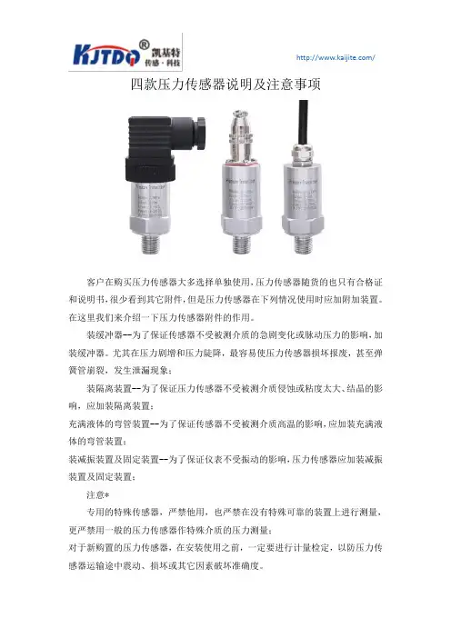
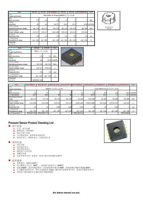
四款压力传感器说明及注意事项
客户在购买压力传感器大多选择单独使用,压力传感器随货的也只有合格证和说明书,很少看到其它附件,但是压力传感器在下列情况使用时应加附加装置。
在这里我们来介绍一下压力传感器附件的作用。
装缓冲器--为了保证传感器不受被测介质的急剧变化或脉动压力的影响,加装缓冲器。
尤其在压力剧增和压力陡降,最容易使压力传感器损坏报废,甚至弹簧管崩裂,发生泄漏现象;
装隔离装置--为了保证压力传感器不受被测介质侵蚀或粘度太大、结晶的影响,应加装隔离装置;
充满液体的弯管装置--为了保证传感器不受被测介质高温的影响,应加装充满液体的弯管装置;
装减振装置及固定装置--为了保证仪表不受振动的影响,压力传感器应加装减振装置及固定装置;
注意*
专用的特殊传感器,严禁他用,也严禁在没有特殊可靠的装置上进行测量,更严禁用一般的压力传感器作特殊介质的压力测量;
对于新购置的压力传感器,在安装使用之前,一定要进行计量检定,以防压力传感器运输途中震动、损坏或其它因素破坏准确度。
了解以上附件的用途对我们平时选择压力传感器附件是很有作用的,平时我们在使用压力传感器的时候遇到这些情况就能知道要选择相应的附件。
以防止被测的压力数据不准确。
EH压力变送器选型手册篇一:关于E+H产品选型方法与型号说明重要内容,请看第2页1、登录德国E+H(全称:Endre+Hauer,中文:恩德斯豪斯)网站/2、点击“Aia”(亚洲)3、点击“China”(中国)4、点击“产品”5、选择你需要了解或购买的产品,如我需要了解订货号10H1H-UF0A1AG4A5AA与10H1H-1F0A1AG4A4AA的区别,则按照以下“流量——电磁流量计——PromagH——Promag10H——产品比较(同一系列不一样型号的信息)或者产品选型(同一型号不同订货号的信息)”,详细请看下面的截图。
查询结果:综下所属,订货号10H1H-UF0A1AG4A5AA与订货号10H1H-1F0A1AG4A4AA两个传感器可以互换,但一定要把变送器里的数据模块换过来(上面是传感器工厂标定的数据),区别仅在过程连接(第1个符号所表示)与电源(第10个符号所表示)不一样。
详解如下:第1个符号表示传感器过程连接“U”代表焊接螺纹接套DIN11850,316L/1.4404“1”代表Tri-Clamp,316L/1.4404关于Tri-Clamp:即TC快速接头(Tri-clamp)常用于啤酒、乳业、饮料、制药等领域接头,材质一般为不锈钢,同时Tri-Clamp也是Alfa-Laval集团Tri-Clover有限公司的注册商标,也称卫生级接头,卫生级管道在食品、医药等生产中洁净要求高的场合广泛采用,生产工艺要求无死角连接,且易清洗,一般情况下压力都不高,也就是俗称的“卡箍”连接,常用的TC接头有焊接端头(2个),垫圈和快装卡箍四个零件组成.市场上很容易买到。
TC接头详细规格可以参考DIN32676-2001饮食业、化工业和医药业用配件.不锈钢管夹具接头.焊接式,德国的标准,看看接头和卡箍的图片,连接好后的样子标准中给出了。
、第2个符号表示连接密封圈“F”代表防腐形式,EPDM关于EPDM:即三元乙丙橡胶,其主要的特性就是具有优越的耐氧化、抗臭氧和抗侵蚀的能力,且在所有橡胶当中,EPDM具有最低的比重,它能吸收大量的填料和油而影响特性不大。
压力传感器国际标准
压力传感器的国际标准包括以下几个方面:
1. ISO 376:2011:机械式压力测量设备的校准和验证。
2. ISO 16842:2014:液位测量仪的总体规范以及压力传感器的特殊要求。
3. IEC 60770:电测量、控制和实验室用电子设备的气动传感器。
4. IEC 60068-2-6:2007:试验规范 - 第2-6部分:试验Fc - 震颤(震动)。
5. IEC 529:验密封电子仪器的规格。
6. IEC 60068-2-32:试验规范 - 第2-32部分:试验Ec - 自由落体。
7. ASTM E18:金属材料的拉伸试验方法。
8. ASTM E4:金属材料的压缩试验方法。
9. ASTM E83:金属材料弹性模量的测定方法。
这些标准旨在确保压力传感器的精度、可靠性、耐用性和性能符合国际认可的要求,以便在各种应用中使用。
压力传感器制造商通常根据这些国际标准对其产品进行设计、测试和认证,以满足全球市场的需求。
压力传感器 QBE9000-P适用于液体和气体介质压阻测量系统·DC0…10V输出信号·测量不受温度变化影响·高温度稳定性·无机械老化和漏电·外螺纹G1/2”·卓越的EMC特性用途QBE9000-P…压力传感器适用于HVAC应用中的静态与动态绝对压力测量,特别是用液体或气体(蒸汽应用)作介质的液压和气动系统。
技术设计QBE9000-P…压力传感器采用压力电阻测量原理运行。
陶瓷膜片(厚膜混合工艺)通过与介质直接接触测量压力。
测量可以转换成直流线性DC 0…10V输出信号。
CE1N1906en Siemens Building Technologies28.10.2003 HVAC Products型号概览QBE9000-P…压力传感器可以连接所有能处理来自压力传感器输出信号为DC0…10V的设备或系统。
机械设计QBE9000-P…传感器为小型装置,不能拆开,不能更换或调整。
附件AQB22.1 传感器固定托架(用于远程安装)。
尺寸见“外形尺寸”。
AQB51.1安装配件包括:·2个黄铜螺纹接合件,2×G1/8”,外螺纹·2个铜密封垫圈,1/8”·每端带有制动螺母的1m长铜管,G1/8”内螺纹·1个G1/8”内螺纹接G1/2”内螺纹的连接件,并带有1个1/2”铜密封垫圈·1个G1/8”内螺纹接R1/2”外螺纹的螺纹连接·安装说明( 编码:35 757)AQB51.1安装配件组件由SERTO供货,但安装配件必须从西门子HVAC产品部订货。
其他安装配件可以直接从SETRO订货。
安装注意事项包装箱中装有传感器和安装说明书。
QBE9000-P…传感器设计成与G1/2”螺纹连接件直接连接。
为了确保防止泄漏,必须采取适当的措施。
为了提供无介质泄漏的试验测定,强烈建议安装适当的测验配件和关闭设备。