ISO-TS 15066-2016 Robots and robotic devices — Collaborative robots
- 格式:pdf
- 大小:4.84 MB
- 文档页数:44
ICS点击此处添加中国标准文献分类号HS 中华人民共和国海关行业标准HS/T XXXXX—2010海关物流监控前端集成系统建设第4部分:RFID设备Customs Logistics Supervisor and Control SystemPart 4:RFID device点击此处添加与国际标准一致性程度的标识(工作组讨论稿)(本稿完成日期:2010-12-21)XXXX-XX-XX发布XXXX-XX-XX实施发布目次前言 (II)1 范围 (1)2 规范性引用文件 (1)3 术语和定义 (1)4 RFID电子标签 (2)要求 (2)封装要求 (2)功能要求 (2)性能要求 (2)接口要求 (3)与RFID电子标签阅读器空中接口 (3)数据格式 (3)兼容性要求 (5)安全性要求 (5)物理安全 (5)数据安全 (5)5 RFID电子标签阅读器 (5)ID号编码规则 (5)要求 (7)外观与结构 (7)外观 (7)结构 (7)功能要求 (7)多标签识别能力 (7)动态识别能力 (7)性能要求 (7)接口要求 (8)与上位机接口 (8)与RFID电子标签接口 (8)软件接口标准 (8)安全性要求 (9)设备状态自检 (9)防止相邻干扰 (9)设备认证 (9)前言HS/T XXXX-2010《海关物流监控前端集成系统建设》分为八个部分:——第1部分数据接口;——第2部分卡口建设;——第3部分油气采集换算系统集成和验收;——第4部分 RFID设备;——第5部分 IC卡设备;——第6部分安全智能锁;——第7部分前端设备准入;——第8部分卡口前端工程验收。
本部分为HS/T XXXX-2010的第4部分。
本标准由中华人民共和国海关总署政策法规司提出。
本标准由中华人民共和国海关总署政策法规司归口。
本标准主要起草单位:海关总署科技发展司、海关总署监管司、海关总署加工贸易及保税监管司、海关总署信息中心、中国国际海运集装箱(集团)股份有限公司、南京三宝科技股份有限公司等。

BSENISO17638-2016焊缝的⽆损检验.磁粒⼦检验EUROPEAN STANDARD NORME EUROPéENNE EUROP?ISCHE NORM EN ISO 17638 November 2016ICS 25.160.40 Supersedes EN ISO 17638:2009English VersionNon-destructive testing of welds - Magnetic particletesting (ISO 17638:2016)Contr?le non destructif des assemblages soudés - Magnétoscopie (ISO 17638:2016) Zerst?rungsfreie Prüfung von Schwei?verbindungen - Magnetpulverprüfung (ISO 17638:2016)This European Standard was approved by CEN on 2 October 2016.CEN members are bound to comply with the CEN/CENELEC Internal Regulations which stipulate the conditions for giving this European Standard the status of a national standard without any alteration. Up-to-date lists and bibliographical references concerning such national standards may be obtained on application to the CEN-CENELEC Management Centre or to any CEN member.This European Standard exists in three official versions (English, French, German). A version in any other language made by translation under the responsibility of a CEN member into its own language and notified to the CEN-CENELEC Management Centre has the same status as the official versions.CEN members are the national standards bodies of Austria, Belgium, Bulgaria, Croatia, Cyprus, Czech Republic, Denmark, Estonia, Finland, Former Yugoslav Republic of Macedonia, France, Germany, Greece, Hungary, Iceland, Ireland, Italy, Latvia, Lithuania, Luxembourg, Malta, Netherlands, Norway, Poland, Portugal, Romania, Slovakia, Slovenia, Spain, Sweden, Switzerland, Turkey and United Kingdom.EUROPEAN COMMITTEE FOR STANDARDIZATIONC O M I TéE UR O PéE N DE N O R M A L I SA T I O NE UR O P?I SC HE S KO M I T E E FüR N O R M UN GCEN-CENELEC Management Centre: Avenue Marnix 17, B-1000 Brussels2016 CEN All rights of exploitation in any form and by any means reservedworldwide for CEN national Members.Ref. No. EN ISO 17638:2016 EBS EN ISO 17638:2016EN ISO 17638:2016 (E)3European forewordThis document (EN ISO 17638:2016) has been prepared by Technical Committee ISO/TC 44 “Welding and allied processes” in collaboration with Technical Committee CEN/TC 121 “Welding and allied processes” the secretariat of which is held by DIN.This European Standard shall be given the status of a national standard, either by publication of an identical text or by endorsement, at the latest by May 2017, and conflicting national standards shall be withdrawn at the latest by May 2017.Attention is drawn to the possibility that some of the elements of this document may be the subject of patent rights. CEN [and/or CENELEC] shall not be held responsible for identifying any or all such patent rights.This document supersedes EN ISO 17638:2009.According to the CEN-CENELEC Internal Regulations, the national standards organizations of the following countries are bound to implement this European Standard: Austria, Belgium, Bulgaria, Croatia, Cyprus, Czech Republic, Denmark, Estonia, Finland, Former Yugoslav Republic of Macedonia, France, Germany, Greece, Hungary, Iceland, Ireland, Italy, Latvia, Lithuania, Luxembourg, Malta, Netherlands, Norway, Poland, Portugal, Romania, Slovakia, Slovenia, Spain, Sweden, Switzerland, Turkey and the United Kingdom.Endorsement noticeThe text of ISO 17638:2016 has been approved by CEN as EN ISO 17638:2016 without any modification.BS EN ISO 17638:2016ISO 17638:2016(E) Contents PageForeword (iv)1 Scope (1)2 Normative references (1)3 Terms and definitions (1)4 Safety precautions (1)5 General (1)5.1 Information required prior to testing (1)5.2 Additional pre-test information (2)5.3 Personnel qualification (2)5.4 Surface conditions and preparation (2)5.5 Magnetizing (2)5.5.1 Magnetizing equipment (2)5.5.2 Verification of magnetization (3)5.6 Application techniques (3)5.6.1 Field directions and testing area (3)5.6.2 Typical magnetic testing techniques (6)5.7 Detection media (9)5.7.1 General (9)5.7.2 Verification of detection media performance (9)5.8 Viewing conditions (10)5.9 Application of detection media (10)5.10 Overall performance test (10)5.11 False indications (10)5.12 Recording of indications (10)5.13 Demagnetization (11)5.14 Test report (11)Annex A (informative) Variables affecting the sensitivity of magnetic particle testing (13)Bibliography (15)ISO 2016 – All rights reserved iiiBS EN ISO 17638:2016ISO 17638:2016(E)ForewordISO (the International Organization for Standardization) is a worldwide federation of national standards bodies (ISO member bodies). The work of preparing International Standards is normally carried out through ISO technical committees. Each member body interested in a subject for which a technical committee has been established has the right to be represented on that committee. International organizations, governmental and non-governmental, in liaison with ISO, also take part in the work. ISO collaborates closely with the International Electrotechnical Commission (IEC) on all matters of electrotechnical standardization.The procedures used to develop this document and those intended for its further maintenance are described in the ISO/IEC Directives, Part 1. In particular the different approval criteria needed for the different types of ISO documents should be noted. This document was drafted in accordance with the editorial rules of the ISO/IEC Directives, Part 2 (see /doc/b748db97f68a6529647d27284b73f242326c3101.html /directives). Attention is drawn to the possibility that some of the elements of this document may be the subject of patent rights. ISO shall not be held responsible for identifying any or all such patent rights. Details of any patent rights identified during the development of the document will be in the Introduction and/or on the ISO list of patent declarations received (see/doc/b748db97f68a6529647d27284b73f242326c3101.html /patents).Any trade name used in this document is information given for the convenience of users and does not constitute an endorsement.For an explanation on the meaning of ISO specific terms and expressions related to conformity assessment, as well as information about ISO’s adherence to the World Trade Organization (WTO) principles in the Technical Barriers to Trade (TBT) see the following URL:/doc/b748db97f68a6529647d27284b73f242326c3101.html /iso/foreword.html. The committee responsible for this document is ISO/TC 44, Welding and allied processes, Subcommittee 5, Testing and inspection of welds.This second edition cancels and replaces the first edition (ISO 17638:2003), which has been technically revised.Requests for official interpretations of any aspect of this document should be directed to the Secretariat of ISO/TC 44/SC 5 via your national standards body. A complete listing of these bodies can be found at /doc/b748db97f68a6529647d27284b73f242326c3101.html .ISO 2016 – All rights reservedBS EN ISO 17638:2016 INTERNATIONAL STANDARD ISO 17638:2016(E)Non-destructive testing of welds — Magnetic particle testing1 ScopeThis document specifies techniques for detection of surface imperfections in welds in ferromagnetic materials, including the heat affected zones, by means of magnetic particle testing. The techniques are suitable for most welding processes and joint configurations. Variations in the basic techniques that will provide a higher or lower test sensitivity are described in Annex A.This document does not specify acceptance levels of the indications. Further information on acceptance levels for indications may be found in ISO 23278 or in product or application standards.2 Normative referencesThe following documents are referred to in the text in such a way that some or all of their content constitutes requirements of this document. For dated references, only the edition cited applies. For undated references, the latest edition of the referenced document (including any amendments) applies. ISO 3059, Non-destructive testing —Penetrant testing and magnetic particle testing — Viewing conditions ISO 9934-1:2015, Non-destructive testing — Magnetic particle testing — Part 1: General principles ISO 9934-2, Non-destructive testing — Magnetic particle testing — Part 2: Detection media ISO 9934-3, Non-destructive testing — Magnetic particle testing — Part 3: Equipment3 Terms and definitionsFor the purposes of this document, the terms and definitions given in ISO 12707 and ISO 17635 apply. ISO and IEC maintain terminological databases for use in standardization at the following addresses:— IEC Electropedia: available at /doc/b748db97f68a6529647d27284b73f242326c3101.html /— ISO Online browsing platform: available at /doc/b748db97f68a6529647d27284b73f242326c3101.html /obp4 Safety precautionsSpecial consideration shall be given to toxic, inflammable and/or volatile materials, electrical safety and unfiltered UV radiation.Magnetic particle testing often creates high magnetic fields close to the object under test and the magnetising equipment. Items sensitive to these fields should be excluded from such areas.5 General5.1 Information required prior to testingPrior to testing, the following items shall be specified (where applicable):a)specific test procedure;b)certification requirements for NDT personnel;ISO 2016 – All rights reserved 1BS EN ISO 17638:2016ISO 17638:2016(E)extent of coverage;state of manufacture;testing techniques to be used;overall performance test;any demagnetization;acceptance level;action necessary for unacceptable indications.5.2 Additional pre-test informationPrior to testing, the following additional information can also be required:type and designation of the parent and weld materials;welding process;location and extent of welds to be tested;joint preparation and dimensions;location and extent of any repairs;post-weld treatment (if any);surface conditions.Operators may ask for further information that could be helpful in determining the nature of any indications detected.5.3 Personnel qualificationMagnetic particle testing of welds and the evaluation of results for final acceptance shall be performed by qualified and capable personnel. It is recommended that personnel be qualified in accordance with ISO 9712 or an equivalent standard at an appropriate level in the relevant industry sector.5.4 Surface conditions and preparationAreas to be tested shall be dry unless appropriate products for wet surfaces are used. It may be necessary to improve the surface condition, e.g. by use of abrasive paper or local grinding to permit accurate interpretation of indications.Any cleaning or surface preparation shall not be detrimental to the material, the surface finish or the magnetic testing media. Detection media shall be used within the temperature range limitations set by the manufacturer.5.5 Magnetizing5.5.1 Magnetizing equipmentGeneral magnetization requirements shall be in accordance with ISO 9934-1:2015, Clause 8. Unless otherwise specified, for example, in an application standard, the following types of alternating current-magnetizing equipment shall be used: electromagnetic yokes;ISO 2016 – All rights reservedBS EN ISO 17638:2016ISO 17638:2016(E)b)current flow equipment with prods;c)adjacent or threading conductors or coil techniques.DC electromagnets and permanent magnets may only be used by agreement at the time of enquiry and order.The magnetizing equipment shall conform to ISO 9934-3.Where prods are used, precautions shall be taken to minimize overheating, burning or arcing at the contact tips. Removal of arc burns shall be carried out where necessary. The affected area shall be tested by a suitable method to ensure the integrity of the surface.5.5.2 Verification of magnetizationFor the verification of magnetization, see ISO 9934-1:2015, 8.2.For structural steels in welds, a tangential field between 2 kA/m to 6 kA/m (r.m.s.) is recommended. The adequacy of the surface flux density shall be established by one or more of the following methods: a)by testing a representative component containing fine natural or artificial discontinuities in the least favourable locations;b)measurement of the tangential field strength as close as possible to the surface using a Hall effect probe; the appropriate tangential field strength can be difficult to measure close to abrupt changes in the shape of a component or where flux leaves the surface of a component;c)calculation of the approximate current value in order to achieve the recommended tangential field strength; the calculation can be based on the current values specified in Figure 5 and Figure 6;d)by the use of other methods based on established principles.Flux indicators (i.e. shim-type) placed in contact with the surface under test provide a guide to the magnitude and direction of the tangential field strength, but should not be used to verify that the tangential field strength is acceptable.NOTE Information on b) is given in ISO 9934-3.5.6 Application techniques5.6.1 Field directions and testing areaThe detectability of an imperfection depends on the angle of its major axis with respect to the direction of the magnetic field. This is explained for one direction of magnetization in Figure 1.ISO 2016 – All rights reserved 3BS EN ISO 17638:2016ISO 17638:2016(E)Keymagnetic field direction αangle between the magnetic field and the direction of the imperfection optimum sensitivity αmin minimum angle for imperfection detection reducing sensitivity αi example of imperfection orientationinsufficient sensitivityFigure 1 — Directions of detectable imperfectionsTo ensure detection of imperfections in all orientations, the welds shall be magnetized in two directionsapproximately perpendicular to each other with a maximum deviation of 30°. This can be achieved using one or more magnetization methods.Testing in only one field direction is not recommended but may be carried out if specified, for example, in an application standard.When using yokes or prods, there will be an area of the component in the vicinity of each pole piece or tip that will be impossible to test due to excessive magnetic field strength. This is usually seen as furring of particles.Care shall be taken to ensure adequate overlap of the testing areas as shown in Figure 2 and Figure 3.ISO 2016 – All rights reservedBS EN ISO 17638:2016ISO 17638:2016(E)Dimensions in millimetresKeyd separation between the poles (yoke/prod )Figure 2 — Examples of effective testing area (shaded) for magnetizing with yokes and prods ? ISO 2016 – All rights reserved 5BS EN ISO 17638:2016ISO 17638:2016(E)Keyeffective area overlapFigure 3 — Overlap of effective areas5.6.2 Typical magnetic testing techniquesMagnetic particle testing techniques for common weld joint configurations are shown in Figure 4, Figure 5 and Figure 6. Values are given for guidance purposes only. Where possible, the same directions of magnetization and field overlaps should be used for other weld geometries to be tested. The width of the flux current (in case of flux current technique) or of the magnetic flow (in case of magnetic flow technique) path in the material, d , shall be greater than or equal to the width of the weld and the heat affected zone +50 mm and in all cases, the weld and the heat affected zone shall be included in the effective area. The direction of magnetization with respect to the orientation of the weld shall be specified.ISO 2016 – All rights reservedBS EN ISO 17638:2016 ISO 17638:2016(E)Dimensions in millimetresd ≥ 75b ≤ d/2β≈ 90od1 ≥ 75b1 ≤ d1/2b2 ≤ d2 – 50d2≥ 75d1 ≥ 75d2 ≥ 75b1 ≤ d1/2b2 ≤ d2 ? 50d1 ≥ 75d2 > 75b1 ≤ d1/2b2 ≤ d2 ? 50Key1longitudinal cracks2transverse cracksFigure 4 — Typical magnetizing techniques for yokes ISO 2016 – All rights reserved 7BS EN ISO 17638:2016 ISO 17638:2016(E)Dimensions in millimetresd ≥ 75b ≤ d/2β≈ 90od ≥ 75b ≤ d/2d ≥ 75b ≤ d/2d ≥ 75b ≤ d/2Figure 5 — Typical magnetizing techniques for prods, using a magnetizing current prod spacing ISO 2016 – All rights reservedBS EN ISO 17638:2016ISO 17638:2016(E)Dimensions in millimetres20 ≤ a ≤ 50 N ·I ≥ 8D 20 ≤ a ≤ 50 N ·I ≥ 8D20 ≤ a ≤ 50 N ·I ≥ 8DKeyN number of turns I current (r.m.s)a distance between weld and coil or cableFigure 6 — Typical magnetizing techniques for flexible cables or coils (for longitudinal cracks)5.7 Detection media5.7.1 GeneralDetection media may be either in dry powder form or magnetic inks in accordance with ISO 9934-2.5.7.2 Verification of detection media performanceThe detection media used shall fulfil the requirements of ISO 9934-2.ISO 2016 – All rights reserved9BS EN ISO 17638:2016ISO 17638:2016(E)Indications obtained with the medium to be verified shall be compared against those obtained from a medium having a known and acceptable performance. For this purpose, the reference indications may be real imperfections,photograph(s), andreplica(s).5.8 Viewing conditionsThe viewing conditions shall be in accordance with ISO 3059.5.9 Application of detection mediaAfter the object has been prepared for testing, the detection medium shall be applied by spraying, flooding or dusting immediately prior to and during the magnetization. Following this, time shall be allowed for indications to form before removal of the magnetic field.When magnetic suspensions are used, the magnetic field shall be maintained within the object until the majority of the suspension carrier liquid has drained away from the test surface. This will prevent any indications being washed away.Depending on the material being tested, its surface condition and magnetic permeability, indications will normally remain on the surface even after removal of the magnetic field due to residual magnetism within the part (mainly at the location of the poles). However, the presence of residual magnetism shall not be presumed and post evaluation techniques after removal of the prime magnetic field source are only permitted when a component has been proven by an overall performance test to retain magnetic indications.5.10 Overall performance testWhen specified, an overall performance test of the system sensitivity for each procedure shall be carried out on site. The performance test shall be designed to ensure a proper functioning of the entire chain of parameters including the equipment, the magnetic field strength and direction, surface characteristics, detection media and illumination.The most reliable test is to use representative test pieces containing real imperfections of known type, location, size and size-distribution. Where these are not available, fabricated test pieces with artificial imperfections or flux shunting indicators of the cross or disc or shim-type may be used.The test pieces shall be demagnetized and free from indications resulting from previous tests.NOTE It can be necessary to perform an overall performance test of the system sensitivity for each specific procedure on site.5.11 False indicationsFalse indications which may mask relevant indications can arise for many reasons, such as changes in magnetic permeability, very important geometry variation in, for example, the heat affected zone. Where masking is suspected, the test surface shall be dressed or alternative test methods should be used.5.12 Recording of indicationsIndications can be recorded in one or more of the following ways by using: description in writing;sketches;10 ? ISO 2016 – All rights reservedBS EN ISO 17638:2016ISO 17638:2016(E)c)photography;d)transparent adhesive tape;e)transparent varnish for “freezing” the indication on the surface tested;f)peelable contrast coating;g)video recording;h)magnetic particle dispersion in an epoxy curable resin;i)magnetic tapes;j)electronic scanning.5.13 DemagnetizationAfter testing welds with alternating current, residual magnetization will normally be low and there will generally be no need for demagnetization of the object under test. If demagnetization is required, it shall be carried out using a defined method and to a predefined level. For metal cutting processes, a typical residual field strength value of H < 0,4 kA/m is recommended.5.14 Test reportA test report shall be prepared.The report should contain at least the following:a)name of the company carrying out the test;b)the object tested;c)date of testing;d)parent and weld materials;e)any post weld heat treatment;f)type of joint;g)material thickness;h)welding process(es);i)temperature of the test object and the detection media (when using media in circulation) throughout testing duration;j)identity of the test procedure and description of the parameters used, including the following:— type of magnetization;— type of current;— detection media;— viewing conditions;k)details and results of the overall performance test, where applicable;l)acceptance levels;ISO 2016 – All rights reserved 11BS EN ISO 17638:2016ISO 17638:2016(E)m)description and location of all recordable indications;test results with reference to acceptance levels;names, relevant qualification and signatures of personnel who carried out the test.12 ? ISO 2016 – All rights reservedBS EN ISO 17638:2016ISO 17638:2016(E)Annex A(informative)Variables affecting the sensitivity of magnetic particle testingA.1 Surface conditions and preparationThe maximum test sensitivity that can be achieved by any magnetic testing method is dependent on many variables but can be seriously affected by the surface roughness of the object and any irregularities present. In some cases, it can be necessary to— dress undercut and surface irregularities by grinding, and— remove or reduce the weld reinforcement.Surfaces covered with a thin non-ferromagnetic coatings up to 50 µm thickness may be tested provided the colour is contrasting with the colour of the detection medium used. Above this thickness, the sensitivity of the method decreases and may be demonstrated to be sufficiently sensitive before proceeding with the test.A.2 Magnetizing equipment characteristicsThe use of alternating current gives the best sensitivity for detecting surface imperfections. Yokes produce an adequate magnetic field in simple butt-welds but where the flux is reduced by gaps or the path is excessive through the object, as in T-joints a reduction of sensitivity can occur.For complex joint configurations, i.e. branch connections with an inclined angle of less than 90°, testing using yokes might be inadequate. Prods or cable wrapping with current flow will, in these cases, prove more suitable.A.3 Magnetic field strength and permeabilityThe field strength required to produce an indication strong enough to be detected during magnetic particle testing is dependent mainly on the magnetic permeability of the object. Generally, magnetic permeability is high in softer magnetic materials, for example, low alloy steels and low in harder magnetic materials, i.e. martensitic steels. Because permeability is a function of the magnetizing current, low permeability materials usually require application of a higher magnetization value than do softer alloys to produce the same flux density. It is essential, therefore, to establish that flux density values are adequate before beginning the magnetic particle testing.A.4 Detection mediaMagnetic particle suspensions will usually give a higher sensitivity for detecting surface imperfections than dry powders.Fluorescent magnetic detection media usually give a higher test sensitivity than colour contrast media, because of the higher contrast between the darkened background and the fluorescent indication. The sensitivity of the fluorescent method will, nevertheless, decrease in proportion to any increase in the roughness of the surface to which magnetic particles adhere and can cause a disturbing background fluorescence.ISO 2016 – All rights reserved 13BS EN ISO 17638:2016ISO 17638:2016(E)Where the background illumination cannot be adequately lowered or where background fluorescence is disturbing, coloured detection media in conjunction with the smoothing effect of a contrast aid will usually give better sensitivity.14 ? ISO 2016 – All rights reservedBS EN ISO 17638:2016ISO 17638:2016(E)Bibliography[1] ISO 9712, Non-destructive testing — Qualification and certification of NDT personnel[2] ISO 12707, Non-destructive testing — Magnetic particle testing — Vocabulary[3] ISO 17635, Non-destructive testing of welds — General rules for metallic materials[4] ISO 23278, Non-destructive testing of welds — Magnetic particle testing — Acceptance levels ? ISO 2016 – All rights reserved 15。
暂态录波型故障指示器技术条件和检测规范(试行)Technical requirements and inspection regulations forTransient state waveform recording type fault indicator暂态录波型故障指示器技术条件和检测规范Technical requirements and inspection regulations forTransient state waveform recording type fault indicator1范围scope本标准规定了暂态录波型故障指示器(以下简称指示器)的使用条件、技术要求、选型原则、试验项目及方法等。
This regulation stipulates the working condition, technical requirements, selection principle, testing subjects and methods of transient state transient fault indicator (use “indicator” for short in the following part).本标准适用于额定电压 6.6kV~35kV、额定频率50Hz的三相交流配电架空线路中监测负荷、指示、上报短路和接地故障线路区段信息的暂态录波型指示器。
This standard is suitable for the transient waveform recording indicator to monitor the load, indication, uploading short circuit and earthing faults, for the three phase AC distribution overhead line with rated voltage of 6.6kv-35kv and rated frequency of 50Hz.2 规范性引用文件normative reference下列文件对于本文件的应用是必不可少的。
家用太阳能光伏电源系统技术条件和试验方法1范围本标准规定了离网型家用太阳能光伏电源系统及其部件的定义、分类与命名、技术要求、试验方法、文件要求以及标志、包装。
本标准适用于由太阳能电池方阵、蓄电池组、充放电控制器、逆变器及用电器等组成的家用太阳能光伏电源系统及部件;其他相关具有太阳能充放电控制器、直流/交流逆变器功能装置及系统等可参考使用,如太阳能路灯、信号塔用、轮船应急用等离网型太阳能光伏电源系统及部件。
2规范性引用文件下列文件中的内容通过文中的规范性引用而构成本文件必不可少的条款。
其中,注日期的引用文件,仅该日期对应的版本适用于本文件;不注日期的引用文件,其最新版本(包括所有的修改单)适用于本文件。
GB/T191—2008包装储运图示标志GB/T20047光伏组件(PV)安全鉴定GB/T22473.1—2021储能用蓄电池第1部分:光伏离网应用技术条件GB/T2297太阳光伏能源系统术语GB/T2423.1—2008电工电子产品环境试验第2部分:试验方法试验A:低温(IEC60068-2-1:2007) GB/T2423.2—2008电工电子产品环境试验第2部分:试验方法试验B:高温(IEC60068-2-2:2007) GB/T2423.3—2016环境试验第2部分:试验方法试验Cab:恒定湿热试验GB/T2423.10—2019环境试验第2部分:试验方法试验Fc:振动(正弦)(IEC60068-2-6:2007) GB/T2423.18—2021环境试验第2部分:试验方法试验Kb:盐雾,交变(氯化钠溶液)GB/T24908—2014普通照明用非定向自镇流LED灯性能要求GB/T29196—2012独立光伏系统技术规范GB31241-2022便携式电子产品用锂离子电池和电池组安全技术规范GB/T32504-2016民用铅酸蓄电池安全技术规范GB/T3859.2—2013半导体变流器通用要求和电网换相变流器第1-2部分:应用(IEC/TR 60146-1-2:2011,MOD)GB40165-2021固定式电子设备用锂离子电池和电池组安全技术规范GB/T4208—2017外壳防护等级(IP代码)GB/T7000(所有部分)灯具GB/T9535地面用晶体硅光伏组件设计鉴定和定型IEC TS61836—2016太阳光伏能源系统—术语、定义和符号ISO4892—1:2016塑料-实验室光源暴露试验方法第1部分:通用指南ISO4892—2:2013塑料-实验室光源暴露试验方法-第2部分:氙弧灯3术语和定义IEC TS61836-2016和GB/T2297界定的以及下列术语和定义适用于本文件。
光伏组件非均匀雪载荷试验1范围本文件定义了一种测试方法,用于确定有框光伏组件在倾斜的非均匀雪载荷影响下的机械性能。
本文件适用于有框光伏组件,其边框在预期安装后会突出于组件下边缘的前面板玻璃表面,因此对从组件表面滑落的雪形成了额外的阻碍。
本文件不适用具有其他边框结构的组件,如边框组成背面框架结构或侧边、顶边、下边缘边框不会额外阻碍积雪滑落的组件。
本文件所定义的试验方法用于确定有框光伏组件的非均匀机械载荷极限。
本文件规定的载荷试验方法仅适用于模拟自然雪载荷分布。
任何人工积雪分布模式(例如除雪或人为分配行为)需另行考虑。
本文不包括消除或缓解不均匀积雪的方法,如增大安装角度(超过60°)。
本文所假设地面积雪和组件表面积雪之间的系数关系,可能不适用于多次降雪间隔期间积雪未完全消融的情景。
本文件不考虑积雪对组件发电的影响。
虽然试验方法包括载荷测试步骤间的等待时间,但本文件没有对组件材料(如前板玻璃)的疲劳行为进行过完整评估。
由于雪载造成的光伏组件典型现场失效表现为玻璃破裂和边框弯曲,本试验方法旨在重现此类失效发生时的载荷状态。
2规范性引用文件下列文件中的内容通过文中的规范性引用而构成本文件必不可少的条款。
其中,注日期的引用文件,仅该日期对应的版本适用于本文件;不注日期的引用文件,其最新版本(包括所有的修改单)适用于本文件。
IEC TS60904-13:2018光伏器件第13部分:光伏组件的电致发光(Photovoltaic devices-Part 13:Electroluminescence of photovoltaic modules)IEC61215-1:2016地面用光伏组件设计鉴定和定型-第1部分:测试要求(Terrestrial photovoltaic(PV)modules-Design qualification and type approval-Part1:Test requirements)IEC61215-2:2016地面用光伏组件设计鉴定和定型-第2部分:试验程序(Terrestrial photovoltaic(PV)modules-Design qualification and type approval-Part2:Test procedures)IEC TS61836太阳能光伏能源系统术语、定义和符号(Solar photovoltaic energy systems -Terms,definitions and symbols)IEC TS62915光伏组件设计定型和安全鉴定重测导则(Photovoltaic(PV)modules-Type approval,design and safety qualification-Retesting)GB/T1.1-2020《标准化工作导则第1部分:标准化文件的结构和起草规则》GB/T1.2-2020《标准化工作导则第2部分:以ISOIEC标准化文件为基础的标准化文件起草规则》3术语和定义下列术语和定义适用于本文件。
图书盘点机器人通用技术条件1范围本文件规定了图书盘点机器人的术语与定义、技术要求、试验方法、检验规则、标志、包装、使用说明书、运输和贮存。
本文件适用于对图书馆图书进行盘点的图书盘点机器人。
2规范性引用文件下列文件对于本文件的应用是必不可少的。
凡是注日期的引用文件,仅所注日期的版本适用于本文件。
凡是不注日期的引用文件,其最新版本(包括所有的修改单)适用于本文件。
GB/T 191-2008 包装储运图示标志GB/T 2423.1-2008 电工电子产品环境试验第2部分试验A:低温GB/T 2423.2-2008 电工电子产品环境试验第2部分试验B:高温GB/T 2423.3-2016 环境试验第2部分:试验方法试验Cab:恒定湿热试验GB/T 4768-2008 防霉包装GB/T 4879-2016 防锈包装GB/T 5048-2017 防潮包装GB/T 5226.1-2019 机械电气安全机械电气设备第1部分:通用技术条件GB/T 13384-2008 机电产品包装通用技术条件GB/T 17626.2-2018 电磁兼容试验和测量技术静电放电抗扰度试验GB/T 17626.8-2006 电磁兼容试验和测量技术工频磁场抗扰度试验GB/T 38124-2019 服务机器人性能测试方法IEC 62849:2016 机器人家用移动机器人性能评估方法 Robotics -- Performance evaluation methods of mobile household robots3术语和定义下列术语和定义适用于本文件。
3.1图书盘点 bookshelf scanning按照设定的模式,定期或临时对馆内图书的实际数量及存放位置进行清查和清点。
3.2图书盘点机器人 bookshelf scanning robot由自主导航装置、盘点装置、人机交互单元、操作系统等组成的具有半自主或自主控制功能,可替代图书馆管理员从事图书盘点作业的移动式机器人。
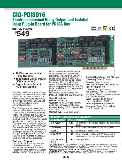
D3-15Model CIO-PDISO16$549ߜ16 Electromechanical Relay Outputsߜ16 Isolated Digital Inputs (500 V Isolation)ߜDigital Inputs Accept AC or DC SignalsProviding 16 electromechanical relays for output actuation and 16 isolated inputs (500 V), the CIO-PDISO16board is a low cost, low profile way to monitor and control high voltage AC or DC directly from your personal computer.The 16 relays are addressed as two 8-bit ports. Ten relays are form C SPDT and 6 are form A normally open. The contacts are rated at 5 A at 120 Vac or 6 A @ 28 Vdc with resistive load. The 16 isolated inputs are also addressed as two bytes.The inputs are not polarity sensitive and may be mixed between 5-24 Vac (50-1000 Hz) and 5-24 Vac (not TTL compatible). Although the connector is a 50-pin header, it maps directly to a 37-pin through the BP40-37 for customers who want to maintain a strict CIO-PDISO8 configuration.Software SupportThe CIO-PDISO16 is supplied with InstaCal software for configuration and testing. In addition, it is also supported by the optional Universal Library. The Universal Library is aset of I/O libraries and drivers for users creating their own custom programs. The Universal Library is compatible with most DOS and Windows (16-bit and 32-bit) based languages (DLL and VXD) and supports the entire CIO family of boards. An optional driver for LabVIEW is also available. Icon driven control programs such as LabtechNotebook, Labtech Control and Dasylab support the CIO-PDISO16.SpecificationsRELAY OUTPUTSQuantity: 16 total; 10 are Form C and 6 are Form A normally open Contact Rating: 28 Vdc @ 6 A, 120Vac @ 5 AContact Type: Gold overlay silverContact Resistance: 100 ΜΩmax Operating Time: 20 msec Release Time: 10 msecLife: 10 million operations, minimum ISOLATED INPUTSQuantity: 16 Opto-isolated,non-polarized. Not TTL compatible Isolation: 500 V channel-to-channel and channel-to-groundInput Range: 5 to 24 Vdc or 5 to 24 Vac 50 to 1000Hz Input Impedance: 470 Ωmin Response Time: 20 μs without filter, 1 ms with filterCIO-PDISO16Electromechanical Relay Output and Isolated Input Plug-In Board for PC ISA BusOMEGACARE SM extended warranty is available for models shown on this page. Ask your sales representative for full details when placing order.Ordering Example: CIO-PDISO16, CIO-MINI50 screw terminal panel, C50FF-2 cable,OMEGACARE SM 1 year extended warranty for CIO-PDISO16 (adds 1 year to standard 3year warranty)and UNIV-DRVR Universal Library: $549 + 69 + 25 + 29 + 49 =$722.CANADA www.omega.ca Laval(Quebec) 1-800-TC-OMEGA UNITED KINGDOM www. Manchester, England0800-488-488GERMANY www.omega.deDeckenpfronn, Germany************FRANCE www.omega.frGuyancourt, France088-466-342BENELUX www.omega.nl Amstelveen, NL 0800-099-33-44UNITED STATES 1-800-TC-OMEGA Stamford, CT.CZECH REPUBLIC www.omegaeng.cz Karviná, Czech Republic596-311-899TemperatureCalibrators, Connectors, General Test and MeasurementInstruments, Glass Bulb Thermometers, Handheld Instruments for Temperature Measurement, Ice Point References,Indicating Labels, Crayons, Cements and Lacquers, Infrared Temperature Measurement Instruments, Recorders Relative Humidity Measurement Instruments, RTD Probes, Elements and Assemblies, Temperature & Process Meters, Timers and Counters, Temperature and Process Controllers and Power Switching Devices, Thermistor Elements, Probes andAssemblies,Thermocouples Thermowells and Head and Well Assemblies, Transmitters, WirePressure, Strain and ForceDisplacement Transducers, Dynamic Measurement Force Sensors, Instrumentation for Pressure and Strain Measurements, Load Cells, Pressure Gauges, PressureReference Section, Pressure Switches, Pressure Transducers, Proximity Transducers, Regulators,Strain Gages, Torque Transducers, ValvespH and ConductivityConductivity Instrumentation, Dissolved OxygenInstrumentation, Environmental Instrumentation, pH Electrodes and Instruments, Water and Soil Analysis InstrumentationHeatersBand Heaters, Cartridge Heaters, Circulation Heaters, Comfort Heaters, Controllers, Meters and SwitchingDevices, Flexible Heaters, General Test and Measurement Instruments, Heater Hook-up Wire, Heating Cable Systems, Immersion Heaters, Process Air and Duct, Heaters, Radiant Heaters, Strip Heaters, Tubular HeatersFlow and LevelAir Velocity Indicators, Doppler Flowmeters, LevelMeasurement, Magnetic Flowmeters, Mass Flowmeters,Pitot Tubes, Pumps, Rotameters, Turbine and Paddle Wheel Flowmeters, Ultrasonic Flowmeters, Valves, Variable Area Flowmeters, Vortex Shedding FlowmetersData AcquisitionAuto-Dialers and Alarm Monitoring Systems, Communication Products and Converters, Data Acquisition and Analysis Software, Data LoggersPlug-in Cards, Signal Conditioners, USB, RS232, RS485 and Parallel Port Data Acquisition Systems, Wireless Transmitters and Receivers。
Comparative Research on Robot Standard System at Domestic and AbroadWANG Yu ,XU Yue ,XING Chao-chao(China Automotive Technology and Research Center <Tianjin>Co.,Ltd.,Tianjin 300300,China )Abstract :Firstly ,this article explains the necessity and importance of the robot standard system ,using Verman's 3D system framework to complete and build the robot standard system framework ,which increases the standard capacity ,which can accurately locate robots standards.Secondly ,further analyzed the standardization organization of international and domestic robot standardization organizations and robot standardization.Thirdly ,compared and analyzed the shortcomings of our robot standard system ,and proposed relevant measures.This research will help accelerate the pace of our robot standard formulation and revision ,and help the industry's health and continuous development.Key words :robot ;Verman 3D structure model ;standardization organization ;standard system ;domestic and foreign comparison机器人标准体系国内外对比研究王雨,徐月,邢超超(中汽研汽车检验中心<天津>有限公司,天津300300)【摘要】首先,阐述了机器人标准化的必要性与重要性,并运用魏尔曼三维体系框架的思想搭建了机器人标准体系框架,该体系提升了标准容量,能够准确定位机器人相关标准;其次,进一步分析了国内外机器人标准化组织及机器人标准化现状;最后,对比分析了我国机器人标准体系存在的不足,并提出了相关举措。
协作机器人的研究现状与与技术发展分析刘洋;孙恺【摘要】随着机器人技术的发展,人机协作成为了可能.多款新概念协作机器人的问世不仅为工业乃至服务业提供了新思路,还让协作机器人成为机器人领域最热门的研究方向之一.其中协作机器人的设计、应用及安全性问题正受到普遍关注.本文对协作机器人的发展现状进行了较为全面的回顾并对其技术现状和未来发展趋势进行了讨论.【期刊名称】《北方工业大学学报》【年(卷),期】2017(029)002【总页数】10页(P76-85)【关键词】人机协作;工业机械臂;轻量机器人【作者】刘洋;孙恺【作者单位】北方工业大学机械与材料工程学院,100144,北京;北方工业大学机械与材料工程学院,100144,北京【正文语种】中文【中图分类】TP241.2近年来,人机协作成为了工业机器人领域最热门的研究方向之一,人与机器协作完成生产任务也十分符合人们对于未来工厂的憧憬.有专家预测,未来十年协作机器人市场将迎来爆炸式发展.2016年3月,国际标准化组织针对协作机器人发布了最新的工业标准,其中对“协作(collaborative operation)”进行了定义:“一个特定设计的机器人系统与一名操作者在同一工作环境下协同工作的状态.”[1]同时进一步明确了安全设计准则.符合标准的协作机器人将足够安全,不再需要防护栏进行隔离.它可与人近距离合作,不仅节省了工作空间,还能满足新兴消费级电子行业小型化、精细化的需求,大大提高工作效率.因此,面对机遇与挑战,对协作机器人进行系统深入的研究,对实现“工业4.0”,助力“中国制造2025”都具有重大现实意义.1 协作机器人发展历程近几年协作机器人获得了广泛关注,其概念的首次提出早在20世纪90年代.1995年通用汽车基金会(General Motor Foundation)赞助了一个项目,试图找到一种方法使机器人变得足够安全以便可以和工人协同工作.1996年,美国西北大学的2位教授J. Edward Colgate和Michael Peshkin首次提出了协作机器人的概念并申请了专利[2].其实在此之前,部分类似协作机器人的研究就已经在一些重点科研机构中展开,并取得了一些阶段性的成果.孵化于麻省理工学院的Barrett Technology公司于1990年成立,其任务是设计研发世界上第一台触觉机器人手臂,该项目也得到了美国能源部、美国国家航空航天局及美国国家卫生基金会的大力支持[3].1995年5月,WAM机械臂首次在美国国家航空航天局肯尼迪航天中心公开亮相,如图1所示.图1 Barrett的WAM以及DLR的三代轻量机械臂德国宇航中心的机器人学及机电一体化研究所从1991年开始研发轻量机器人LWR(light weight robot).为完成两年后的ROTEX空间站任务,使宇航员在地球上能够拥有与太空中对应的机器人进行任务训练[4],该中心于1991年研制出了第一代轻量机器人LBR I.随着研发的不断深入,LBR II(1998)[5]与LBRIII(2003)[6]相继问世,如图1所示.2003年,在德国联邦科教部的支持下,该中心与KUKA联手,产品向工业协作机器人转型.从2004年的Robo Assistant到今天人们熟知的LBR iiwa(intelligent industrial work assistant),无一不是两个机构智慧与合作的结晶.2005年,协作机器人在工业应用中迎来发展契机.由欧盟第六框架计划资助的小中型企业项目于2005年3月开始实施.该项目旨在通过机器人技术增强中小型企业劳动力水平,降低成本,提高竞争力.其中,SME robot项目由德国顶级自动化技术应用研究所之一——弗劳恩霍夫协会制造技术与自动化研究所(FhG-IPA)负责承担,同时参与该项目的还有德国宇航中心(DLR)、瑞典隆德大学工程系(LTH)、其他大学及科研机构、IT公司、软件开发商以及咨询公司[7].同年,Universal Robots在丹麦成立.图2 Motoman的SDA10、SIA102006年,日本安川电机公司机器人分部(Motoman)将双臂机器人引入欧洲市场[8].其推出的SDA系列与SIA系列轻型机械臂,如图2所示,与现在的主流协作机器人在结构与外观上已相差无几.但当时的Motoman更倾向“机器换人”及“多机器人协作”,而非“人机协作”,因此这2个系列机器人只能做到机器之间的相互协作,而无法与人共享工作环境.即便如此,这在当时依然引起了不小的轰动.2008年,Universal Robots推出了世界上第一款符合当前意义的协作机器人UR5,之后又推出了UR10(2012)以及UR3(2015).随着UR系列异军突起,协作机器人市场的大门被打开,以“四大家族”为首的传统工业机器人企业纷纷将目标指向了这一新领域.KUKA的LBR iiwa(2013)、ABB的Yu Mi(2014)、FANUC的CR-35iA(2015)以及Motoman的HC10(2015),每当这些产品在各大工业会展中亮相时,都能引来各界的广泛关注.与此同时,许多新兴科技企业也如雨后春笋般,积极投身到协作机器人的研发之中.代表产品有rethink robotics的baxter(2012)和sawyer(2015),其独特的人机交互功能让人印象深刻,以及Kinova Robotics专为服务业及残疾人设计的JACO2(2015).2016年3月,国际标准化组织针对协作机器人发布了最新的工业标准——ISO/TS 15066:Robots and robotic devices-Collaborative robots.作为支持ISO 10218的补充文档,该标准进一步明确了协作机器人的设计细节及系统安全技术规范,所有协作机器人产品必须通过此标准认证才能在市场上发售[9].由此,协作机器人在标准化生产的道路上步入正轨.2 国际主流协作机器人简介目前的协作机器人市场仍处于起步发展阶段.现有公开数据显示,来自全球的近20家企业公开发布了近30款协作机器人.根据结构及功能,本文选取了7款极具代表性的协作机器人进行简要介绍,其中包括Universal Robots的UR5、KUKA的LBR iiwa、ABB的YuMi、FANUC的CR-35iA、Motoman的HC10、rethink robotics的sawyer以及Kinova Robotics的JACO2.2.1 UR5UR5六轴协作机器人是Universal Robots于2008年推出的全球首款协作机器人,有效负载5kg,自重18kg,臂展850mm,外接Teach Pendant控制器,支持拖动示教,UR系列机器人如图3所示.图3 UR系列UR5具有编程简单、安装迅速、部署灵活、安全可靠等特点[10],其超高的性价比让人印象深刻.UR5采用其自主研发的Poly Scope机器人系统软件,该系统操作简便,容易掌握,即使没有任何编程经验,也可当场完成调试并实现运行.正常情况下,UR机器人的安装只需2~3小时,可以安装在桌面上,也可以安装在设备上,甚至天花板上,极大限度提升了设备的使用灵活性从而提高了生产效率.结构上采用模块化关节设计,通过监测电机电流变化获取关键的关节力信息,实现力反馈,从而在保证安全性的同时摆脱了力矩传感器,生产成本大大降低,极大程度提高了市场竞争力.UR机器人目前已得到一些知名企业的认可并进入生产线与工人协同作业.Volkswagen于2013年将UR机器人整合投入其萨尔茨吉特引擎生产工厂的大规模生产线中.这是Volkswagen在全球首次使用协作机器人[11].东风雷诺汽车有限公司将UR10机器人用于发动机装配线上.这是中国汽车发动机装配线首次使用协作型机器人[12].除此之外,全球知名汽车零部件供应商Lear Corporation Limited以及ODM代工公司纬创资通也将UR机器人引入了各自的生产线中,实现了工作优化.2.2 LBR iiwaLBR iiwa七轴协作机器人是KUKA与DLR于2013年联合推出的第五代轻型机械臂,该机器人于2014年11月上海工博会正式面向中国发布[13].LBR iiwa具有2种型号:LBR iiwa 7有效负载7kg,自重约23.9kg,臂展800mm;LBR iiwa 14有效负载14kg,自重约29.9kg,臂展820mm.2种机器人均外接KUKA smartPAD控制器,支持拖动示教.与iiwa类似的协作机器人有Schunk的LWA 4D以及KBee的FRANKA EMIKA,如图4所示.图4 七轴协作机器人LBR iiwa专为工业设计,具有灵活、安全、灵敏、精确等特点.机身采用全铝制材料,不但减轻了重量,还提高了安全性.流线型的外观设计体现了力与美的结合,同时消除了由棱角带来的挤压与剪切所造成的安全隐患.LBR iiwa的全部7个关节均配备了高性能的集成力矩传感器,体积小,灵敏度高.当运行中发生意外接触时,iiwa能实现立即减速,避免伤害.精度方面,所有齿轮单元均采用系统化精度设计及一流的制造工艺,这使得iiwa的重复度达到±0.1mm.通过导入力矩信号,LBR iiwa能够在路径控制中实现独特的平滑运动,这也使操作者在拖动示教过程中能够顺利将机器人摆放至最佳姿态,手把手“教会”机器人如何高效率地工作.2016年7月,福特汽车公司(Ford Motor Company)展示了其应用于德国科隆Fiesta工厂中的LBR iiwa.在工作中,该协作机器人能够帮助工人安装汽车减震器,确保减震器放置的准确性、快速性,减少了工人的负担.2.3 YuMiYuMi(IRB 14000)是ABB推出的全球第一款双臂协作机器人,如图5所示.YuMi 的设计与研发始于2009年,2015年4月德国汉诺威工业博览会上正式面向市场发售.YuMi整体重量38kg,单臂7轴冗余设计(双臂14轴),有效负载0.5kg,臂展500mm,外接IRC5控制器,支持拖动示教.YuMi专为消费级电子产业设计,具有极高的精度、安全性及灵活性.每只手臂均可高效模仿人类动作,既可单独作业,也可实现臂与臂的协作.其末端工具速度最高可达1.5m/s,位置重复度高达0.02mm.由于末端速度较快,YuMi在安全性方面引入了许多独特的设计.机械臂骨骼采用轻质钢化镁材料,表面包裹了柔软的漂浮塑料.当发生意外接触或碰撞时,机械臂能在几毫秒内停止运动,同时塑料层也能很大程度上吸收接触力,起到减震防护作用.YuMi在保证安全性的同时兼顾了工作效率,大大提高了协作机器人在工业生产中的实用性.图5 YuMi2.4 CR-35iA2015年11月的上海工博会,FANUC在中国地区正式推出全球负载最大的六轴协作机器人CR-35iA,如图6所示.其自重990kg,有效负载35kg,臂展1813mm,外接R-30iB控制器,支持拖动示教.图6 基于传统结构的六轴协作机器人CR-35iA可以说是协作机器人中的“绿巨人”.为实现高负载,FANUC公司没有采用轻量化设计,而是在传统工业机器人的基础上进行了改装升级.虽然在结构上与传统工业机器人极为相似,但CR-35iA整个机身由绿色软护罩包裹,内置iRVision视觉系统,同时具有意外接触停止功能,这使得机器人能够很好地缓和冲击力,防止人被夹住,从而实现与人共享工作环境.得益于其高负载,CR-35iA 可协同工人完成重零件的搬运及装配工作,例如组装汽车轮胎或往机床搬运工件等.FANUC公司在CR-35iA之后进行了轻量化产品补充.以CR-35iA为基础,他们陆续推出了CR-4iA、7iA及7iA/L,负载/臂展分别为4kg/550mm、7kg/717mm以及7kg/911mm.整个系列产品灵活配置,能够充分满足不同工况的需求,同时保持操作上的一致性.市面上类似的产品还有Precise Automation的PAVP6,如图6所示.2.5 HC10HC10六轴协作机器人是Motoman的最新产品,也是其推出的第一款协作机器人,初次亮相于2015年12月的东京“2015国际机器人展”.HC10有效负载10kg,臂展1200mm,外接YRC 1000控制器,支持拖动示教.其他类似的协作机器人有ABB的Roberta、Schunk的LWA 4P、F&P Personal Robotics的P-Rob®2R以及MABI的Speedy 6,如图7所示.图7 当前流行的六轴协作机器人HC10在外形设计上无夹点或棱角,表面包裹了一层柔软的蓝色橡胶材料以吸收意外碰撞产生的接触力.所有关节都配备了精密的力/力矩传感器,一旦检测到与操作者的意外接触,机器人就会立即停止工作.除上述特点外,HC10的最大特色在于其具备多种工作模式.“协作模式”下,HC10将最大程度上保证操作者的安全,运行速度会受到限制;当切换至“高速工业模式”时,机械臂运行速度将大幅提升,工作效率也将达到传统工业机器人水平,因此该模式下也要采取必要的安全措施,如进行安全区域监测,设置防护栏等.为获得工业机器人国际安全标准“ISO/TS15066”的认证,HC10正在接受评估,预计2017年正式发售.2.6 sawyer2015年3月,Rethink Robotics公司继baxter之后推出了其第二代智能协作机器人sawyer,如图8所示.sawyer具有7个转动关节,自重19kg,有效负载4kg,臂展1260mm.无外接控制设备,所有按键及显示屏均在机器人本体上,操作灵活、简单、直观.图8 sawyer、baxterRethink Robotics对协作机器人见解独到,设计新颖别致.sawyer采用了功率和力度受限的柔性机械臂设计,每个关节都配备了高分辨率的力度传感器以及串联弹性驱动器.这不仅保证了安全,还极大程度提高了机械臂的柔顺度及依从性,使人操作起来轻松顺手.sawyer具有极高的自适应精确度,能够在半结构化的环境中有效完成公差为0.1mm的实际应用.此外,sawyer还拥有一个强大的嵌入式视觉系统,顶部摄像头用以获得广阔的视野,腕部的Cognex摄像头配合机器人定位系统可实现机器人的实时动态定位.sawyer最大的特点莫过于它那张让人印象深刻的“脸”——一块置于基座上方的显示屏,这也是rethink robotics最具标志性的设计.当用户配置参数时,屏幕上会显示相关信息,当机器人开始工作时,屏幕上就会出现一双“眼睛”.这双眼睛时刻盯着当前的工作位置,配合眉毛组成丰富的表情,界面显示当前工作是否顺利.这种人性化的交互界面以最直观的方式实现了机器人工作状态的实时监控,同时为枯燥的工业生产增添了许多乐趣.sawyer应用广泛,在电路板测试、物料处理、包装以及生产线加载等领域均具备较强的工作能力.截止目前,通用电气公司(GE)已将sawyer机器人部署于北卡罗来纳州亨德森维尔的GE照明工厂中.Steelcase也将sawyer部署于密歇根州大溪城的工厂,以配合焊接机器辅助生产.2.7 JACO22015年,Kinova Robotics推出其最新款6轴带3根手指机械臂JACO2,如图9所示.机械臂连杆部分采用碳纤维材料,整体重量5.2kg,有效负载1.3kg,臂展900mm,配备简易遥控装置,包括一个3自由度摇杆及7个按键.JACO2协作机器人主要用于服务行业及残疾人辅助事业.服务业方面,JACO2在移动操作、医疗、物流及研究领域都有广泛应用.轻巧精致的机械臂能够搭载于绝大多数移动平台,其能耗较低,不会影响到平台自身性能.机械臂的模块化配置及驱动器的低后坐力使其能够很好地帮助医生进行手术.机械臂能自动完成探测抓取操作或协助工人工作,提高工作效率,改善工作质量.在辅助残疾人方面,根据全球不同地区的轮椅空间特点,JACO2可选择安装在轮椅座位支架旁的合适位置.为便于移动,多数情况下控制器会安装在轮椅的另一侧.机器人可以帮助使用轮椅的残障人士独立完成许多日常活动,如吃饭、喝水、擦脸、开门、按按钮(如电梯)、捡东西、作画等.JACO2在全球范围内销售,目前在荷兰,已有超过150名用户利用协作机器人实现了独立生活.图9 JACO23 核心零部件绝大多数协作机器人在设计上都要遵循轻量化安全设计准则,因此对关节集成度提出了非常高的要求,所需核心零部件也与传统工业机器人有很大区别,如中空伺服电机、谐波减速器[14]、模块化编码器、伺服驱动器以及安全控制器等,如图10所示.正是这些核心零部件决定了一台协作机器人的结构及性能.图10 核心零部件电机是机器人的动力来源,直接影响其有效负载、工作半径等关键参数.传统工业机器人大多使用交流伺服系统,工艺成熟,可选范围广.协作机器人通常要在内部走线,必须使用中空电机.除了科尔摩根(Kollmorgen)的产品外,目前市面上还没有非常合适的替代品.在涉及防护功能的安全控制器方面,市面上虽然也有不少现成的产品,但大多是面向流程工业的安全PLC.这些控制器不但价格昂贵,还无法实现协作机器人的某些专用安全功能,如速度限制,力矩限制,空间限位等.对于谐波减速器、模块化编码器以及伺服驱动器等也有同样的问题.由于协作机器人是近两年的新兴产物,很多关键零部件还没有实现大规模生产,不仅选择受限,价格也十分昂贵,这就对开发人员提出了很高要求.因此,协作机器人的设计绝不是简简单单的零件拼凑,而是要将尽可能多的零部件集成在尽可能小的空间内,其中涉及很多细节问题,任何疏忽都会造成严重后果,直接影响产品的定型和生产.4 国内发展现状2015年底,由北京大学工学院先进智能机械系统及应用联合实验室、北京大学高精尖中心研制的人机协作机器人WEE先后在上海工博会、深圳高交会、北京世界机器人博览会上参展亮相,表现抢眼[15].WEE双臂协作机器人具有高负载自重比(1∶2)、全方位动态补偿控制方法、完整的力控制策略运用、先进的智能人机界面等特点.它不仅拥有独立自主知识产权,还是一台具备国际先进水平的高带宽、轻型、节能工业协作机器人,目前WEE正处于产业推广阶段.商业上,我国协作机器人成品化进程相对较晚,但也取得了一些可喜的成果,如新松、大族、遨博、达明机器人等都相继推出了自己的协作机器人,如图11所示.在2015年11月的上海工博会上,我国最大的机器人产业化基地、机器人产业的龙头企业——沈阳新松自动化股份有限公司推出了国内首款高端7轴人机协作机器人[3].这款柔性多关节机器人具有快速配置、牵引示教、视觉引导、碰撞检测等功能,具备高负载及低成本的有力优势,能够满足用户对于投资回报周期短及机器人产品安全性、灵活性及人机协作性方面的需求.图11 国产协作机器人2016年的上海工博会,大族电机携最新产品Elfin六轴协作机器人精彩亮相.机械臂采用模块化安装,装配快捷,控制简单,维修方便,成本较低.其自重21kg,额定负载5kg,重复精度可达±0.1mm,能够满足生产需求.作为协作机器人,Elfin可配合工人工作,也可用于集成自动化产品线、焊接、打磨、装配、搬运、拾取、喷漆等工作场合,应用灵活广泛.5 发展前景及研究方向2002年,Rodney Brooks(rethink robotics现任董事长兼CTO)曾预言:“到2020年,机器人将遍及我们的生活.”[16]他的这一观点随后得到了世界首富的回应,Bill Gates在2007年表示,不久“机器人就会进入千家万户”[17].有人将2016年称为协作机器人元年.根据巴克莱银行(Barclays Bank)的预测,到2025年,全球协作机器人的销售额将从2015年的1.16亿美元增长到115亿美元.协作机器人主要面向中小型企业,全球中小型企业约600万家,占全球制造业的近七成.因此协作机器人在工业领域的增长方向十分清晰,如果包括在服务业中的尝试与拓展,巴克莱的预测也许仅仅是“保守估计”.面对如此广阔的市场前景,许多企业及科研机构都加紧了对协作机器人的研究与开发工作,主要在以下4个方面:1)人机交互.人与机器交流互动是实现人机协作的关键.这里的“交互”并不仅仅停留于语音或肢体层面,更多是指广义上的控制与反馈.在控制手段上,目前多数协作机器人依然保留了传统工业机器人的控制模式,即配备专门的控制面板.一些创新产品,如baxter、sawyer以及FRANKA EMIKA已经在一定程度上脱离了对外部设备的依赖,实现了由“台式机”向“一体机”的转变.在控制方法上,可拓展空间巨大.传统方法是使用控制器编辑指令对机器人运动进行控制[18],如今随着人与机械臂的近距离接触,拖动示教(“手把手教”)已被广泛应用.其中部分机器人还集成了视觉系统,机器人可通过“观察”进行学习和调整[19].此外,还有研究人员利用惯性测量单元(IMU)对机器人进行体感示教,让机器人实现与人的非接触同步运动,这在对精度要求不高的服务业非常实用.目前最受关注的当数协作机器人在人工智能领域的探索.随着AlphaGo的强势表现,人工智能尤其是深度学习[20]在全球掀起了一股狂潮,让协作机器人具备自学能力已成为各企业及科研机构的热门选题.2)安全性研究.安全是人与机器共享工作环境的前提.对于协作机器人的安全性研究,ABB的科研人员做出了突出贡献.首先,他们对人与机器的接触部位及受伤类型进行了分类,提出了风险评估方法[21-22];其次他们进行了碰撞实验[23],故障诊断及故障隔离[24];最近他们又提出了以安全为硬约束的运动控制策略[25].完备的理论及实验支撑,让YuMi在安全性方面得到了业内的一致好评.除此之外,许多其他科研人员也进行了广泛深入的研究,其中包括对协作机器人在工作过程中保持高度依从性[26]的研究,以及利用残余信号探测人与机器是否接触,并利用深度传感器确定接触位置[27]的研究等.相信随着研究的深入,人与机器共处将不再有任何心理负担,同时能更高效地协同完成工作任务.3)动力学研究.动力学一直以来都是机器人领域的重点研究方向.尤其在协作机器人当中,准确获取外部力信息成为其运动控制及安全防护的关键.较为直观的方法是在每个关节都安装力矩传感器进行测量,进而估算出机器人末端的外部力[28].这种方法对硬件设计要求较高,在实际生产当中成本也很大.因此,不少研究人员正努力通过其他方法进行力测量以摆脱传感器的束缚.例如,有研究人员利用干扰观测器进行机器人末端外部力及各关节的干扰力矩的估算[29];还有研究者通过获取电机的电流/转矩及关节转角信号重建外部力信息[30].随着动力学的深入研究,协作机器人成本将进一步降低,更多柔性材料将会被引入,大大提高协作机器人的安全性与灵活性.4)结合特定产品的研究.近年来,协作机器人发展势头迅猛,许多产品不仅为工业生产提供了新思路,还为高校及科研院所提供了新的实验平台.结合特定产品的研究在各地高校展开,形式多种多样.其中包括对产品内部参数的研究,如对KUKA LWR4+动力学参数的研究[31],以及对baxer的DH运动学模型重建[32];以产品为实验平台结合其他设备或技术的研究,如以KUKA LWR-IV为平台结合Kinect传感器对机器人避障的研究[33],以及以baxter为平台结合人体工程学问题对机械臂运动人性化的研究[34];还有对产品应用的拓展,如为baxter增加下棋功能[35],以及利用baxter进行高度可变性材料的研究[36]等.如果将协作机器人硬件结构进行细分,研究方向还包括结构设计、外观设计、控制器设计、模块化关节设计、关键零部件设计等,在此就不一一赘述.6 结语协作机器人是近两年刚刚兴起的一个研究热点,虽已有多款产品问世,但仍有许多问题亟待解决.首先,目前对协作机器人系统的理论研究仍处于发展阶段,尚没有一套成熟的理论作指导.其次,目前协作机器人的生产成本普遍较高,部分核心零部件需要专门订做,价格不菲.此外,关于协作机器人的应用尚没有明确定位,协作机器人能干什么,最适合干什么,怎样跟人配合工作效率最高等,都没有一个定量的回答.对于国内而言,问题更多,挑战更大.由于起步较晚,国内机器人领域人才资源匮乏,组建高水平的机器人团队并非易事.此外,由于技术条件限制,关键零部件的国产化目前还没有完全实现,如果采用进口零部件,成本势必大大提高,。
引言关于本手册本手册是为了让技术人员快速、正确、安全地安装、使用AIR6SC600-A型工业机器人,熟悉相关注意事项以及对操作机做定期常规维护工作。
操作前提在操作机器人前,请务必仔细阅读产品的通用安全说明和安全预防措施,用户需在了解安全知识和基础操作知识之后,才可操作机器人。
请在必要时参阅:◼《inCube2S 控制柜手册》◼《SCARA型示教器操作手册》◼《ARL 编程手册》◼《AIR6SC600-A 水平多关节型工业机器人系统快速入门手册》目标群体◼操作人员◼产品技术人员◼技术服务人员◼机器人示教员常见标识含义手册中出现标识及其含义详见下表1。
表1 本文中使用的标识手册说明本手册内容会有补充和修改,请定时留意我公司网站的“下载中心”,及时获取最新版本的手册。
我公司网站网址:/修订记录修订记录累积了每次文档更新的说明。
最新版本的文档包含以前所有文档版本的更新内容。
表2 文档修订记录文档编号及版本文档编号及版本信息见表3。
表3文档相关信息适用安全标准的声明工业机器人系统设计符合的要求详见表4。
表4 适用安全标准的声明通用安全说明感谢贵公司购买本公司操作机,本说明资料为安全使用操作机而需要遵守的内容,在使用操作机之前,请务必仔细阅读相关手册,并且在理解该内容的前提下正确使用操作机。
有关操作机的详细功能,请用户通过相关说明书充分理解其规格。
安全注意事项一般情况下,操作机不能单个进行作业,只有安装上末端执行器,构架起外围设备和系统才可以进行作业。
在考虑其安全性时,不能将操作机独立起来考虑,而应将其置于系统环境中考虑。
警告、注意和提示本说明书包括保证操作人员人身安全以及防止操作机损坏的注意事项,并根据它们在安全方面的重要程度,在文中以“警告”和“注意”来叙述,有关补充说明以“提示”来描述。
用户在使用操作机之前,必须熟读这些“警告”、“注意”和“提示”中所叙述的事项。
一般注意事项安装时注意事项操作时注意事项目录引言 (I)通用安全说明 (IV)目录 (I)1产品规范 (1)1.1一般功能和预定用途的应用范围 (1)1.2环境条件与工作和储存的限制 (1)1.2.1使用环境要求 (1)1.2.2长期储存环境条件 (1)1.2.3储存相关注意事项 (2)1.3基本规格 (2)2机器人系统介绍 (4)2.1工业机器人简介 (4)2.2操作机基本构成 (4)2.3产品标签及含义 (5)3使用前的准备 (8)3.1使用前的安全防护措施 (8)3.2拆包 (9)3.2.1拆包方式 (9)3.2.2包装材料的安全处置 (10)3.2.3废弃材料处置 (11)3.3安装前的准备工作 (11)3.3.1安装注意事项 (11)3.3.2安装工具及所需连接件 (11)3.4安装和装配 (11)3.4.1技术规格 (11)3.4.2固定方式 (12)4电气接口 (14)4.1操作机电气接口类型 (14)4.2本体侧重载线接口 (16)4.3柜体侧重载线接口 (18)4.4操作机用户I/O接口 (19)4.5电源线接口 (20)5工作说明 (22)5.1安全注意事项 (22)5.2安全运行 (23)5.2.1LED指示灯 (23)5.2.2结构尺寸 (23)5.2.3各轴工作范围 (24)5.2.4机械限位 (25)5.2.5停止方式 (26)5.3标定 (26)5.3.1何时需要标定 (26)5.3.2各轴标定位置 (26)5.3.3各轴运动方向 (28)5.3.4各轴速度 (28)5.4法兰连接尺寸 (29)5.5负载安装 (29)6运输与搬运 (31)6.1搬运姿态 (31)6.2搬运尺寸 (32)6.3搬运方法 (33)7预防性的维护 (35)7.1安全防护措施 (35)7.2日常维护 (36)7.3首次维护 (37)7.4定期维护 (38)7.5润滑脂加注 (40)8项目维护流程 (41)8.1清洁操作机 (41)8.2检修线缆 (41)8.3更换电池 (43)8.4更换同步带 (44)9故障查找、诊断和维修 (52)附录A AIR6SC600-A型操作机定期维护表 (58)附录B 螺钉强度及螺钉拧紧力矩表(NM) (59)1产品规范1.1一般功能和预定用途的应用范围工业机器人系统用于搬运工具和装置,或加工和运输工件或产品。
Overview: ISO/TS 15066:2016Carole FranklinDirector of Standards DevelopmentRobotic Industries Association (RIA)Now Also Available As RIA TR R15.606-2016•What Is TS 15066 / TR 606?•Why Is TS 15066 / TR 606 Important?•How Can It Help You?•What’s Next for Collaborative Robot Standards?•Now Also Available As RIA TR R15.606-2016•What Is 15066 / TR 606?•Why Is 15066 / TR 606 Important?•How Can It Help You?•What’s Next for Collaborative Robot Standards?•ISO/TS 15066:2016–an ISO Technical Specification •RIA TR R15.606-2016–An ANSI-registered Technical Report •Shorthand: “15066” or “TR 606”•Order & download PDF from RIA Webstore:/bookstore-cat.cfm?category_id=118/Online-Store>> Industrial Robot Standards link •Important! Supplemental to ISO 10218 / R15.06•“Industrial Robots and Robot Systems –Safety Requirements”“”Robot Definition from ISO 10218 / R15.06•Industrial Robot=Robot Arm+Robot Controller •Industrial Robot System=Robot+End-Effector+Workpiece •The End-effector and Workpiece are determined based on theApplication–or, what the robot is intended to accomplish•Might be a... ?•Sealant applicator•Gripper•Cutter•Welder•...•...Source: R15.06-2012, Part 1, Clauses 3.10 and 3.11What Is 15066 / TR 606?Short Version:“Safety Requirements for Collaborative Industrial Robot Systems”Even Shorter:“Collaborative Robot Safety”A “Collaborative Robot” is...“...[a] robot designed for direct interaction with a humanwithin a defined collaborative workspace.” 1“Collaborative Operation” is...“…[a] state in which a purposely designed robot systemand an operator work within a collaborative workspace.” 2The “Collaborative Workspace” is...“...[the] workspace within the safeguarded space where the robot and a human can perform tasks simultaneouslyduring production operation.” 3Sources: 1 –R15.06-2012, Part 2, Clause 3.2;2 –ISO/TS 15066:2016, 3.1;3 –R15.06-2012, Part 1, 3.5•Collaborative Robot?•“Power-and Force-Limited Robot” (PFL)•Collaborative Application•Collaborative Operation•Collaborative Robot SystemA Collaborative Robot System is......one in which the human and the robot systemcan occupy the same workspace, at the same time,while the system is in automatic mode.•Does it mean there are no safeguards?•(Hint: No. The “collaborative workspace” is within the “safeguarded space”.)•Does it mean, take the fence away and now we are collaborative?•(Also No.)•Does it mean, get a “collaborative robot” (PFL) and now we are collaborative?•(Still No. If the “collaborative” (PFL) robot arm is juggling knives, that is a non-collaborative application –or should be.)•If it’s a “collaborative robot,” does that mean I don’t need to do a risk assessment?•(You guessed it... No. You must still do a risk assessment.)What Is 15066 / TR 606?Short Version:“Safety Requirements for Industrial Collaborative Robot Systems”Even Shorter:“Collaborative Robot Safety”•A good first step•A solid foundation•Likely to be updated and refined as more studies are doneOverview: ISO/TS 15066:2016•Now Also Available As RIA TR R15.606-2016•What Is 15066 / TR 606?•Why Is 15066 / TR 606 Important?•How Can It Help You?•What’s Next for Collaborative Robot Standards?•Paradigm Shift•Old: Primary means of protecting people was to separate them from the robotic equipment•Physical safeguards and protective devices•Paradigm Shift•New: With the advent of Collaborative Robot Systems, now the human and robot system can interact in the shared workspaceUnique strengths of humans (creative problem-solving)Unique strengths of robot systems (power and precision in repetitive tasks) Increased productivity in industry and throughout the economy.•Collaborative robot systems will have built-in safety capabilities to reduce risks to the human worker.•Key collaborative techniquesinclude...•Safety-rated monitored stop•Hand guiding•Speed and separation monitoring•Power and force limiting•TS 15066 integrates key information together in one document: •Definition of collaborative robotic operation•Characteristics of safety-related control systems for collaborative operation •Factors for the design of a collaborative robot system*•Built-in safety-related systems for collaborative operation, and requirements for their use;•How to implement a collaborative application using the following techniques: •Safety-rated monitored stop•Hand guiding•Speed and Separation Monitoring•Guidance on speeds, protective distances, formula for protective separationdistance*•Power and Force Limiting•Threshold limit values for power and force to avoid pain** New Information in 15066/ TR 606!•New information:•Annex A:“The Body Model”incorporates important datafrom a study of pain thresholdsfor Power and Force Limitingapplications•Study conducted at theUniversity of Mainz in Germany•100 human test subjects; bothsexes and wide range of agesand body dimensions•Maximum permissible pressurevalues shown in Annex Arepresent the 75th percentileSources: ISO/TS 15066:2016, Annex A;http://www.dguv.de/ifa/fachinfos/kollaborierende-roboter/schmerzschwellenkataster/index-2.jsp•New information:•Annex A:“The Body Model”Source: ISO/TS 15066:2016, Fig. 4, Fig A.1Overview: ISO/TS 15066:2016•Now Also Available As RIA TR R15.606-2016•What Is 15066 / TR 606?•Why Is 15066 / TR 606 Important?•How Can It Help You?•What’s Next for Collaborative Robot Standards?How Can TS 15066 / TR 606Help You?•Guidance primarily for suppliers and integrators for the safe design and operation of collaborative robot systems.•Four types of collaborative operation:•Safety-rated monitored stop•Hand guiding•Speed and separation monitoring•Power and force limitingHow Can TS 15066 / TR 606 Help You?Why is TS 15066 / TR 606 Important?•Safety-Rated Monitored Stop •A stop is assured while maintainingpower to the robot•Operator may interact with robot•Automatic operation may resume whenthe human leaves the collaborativeworkspace (requires safeguarding)•Either the person OR the robot systemmay move, but NOT at the same time.•Hand guiding•Operator is in directcontact with the robot andis using hand controls todirect the robot where to goand what to do•Robot system undermanual control•Both the person and therobot may move at thesame time; motioncontrolled by the person•Speed and separation monitoring•Robot/hazard speed is reduced the closer an operator is to the hazard area •Protective stop is issued when operator is in potential contact•Person and robot may move at the same time•Power and force limiting•Speed, torque, motion of the robot is controlled so that incidental contact between robot and operator will not cause harm•Since contact is permitted, it must be controlled and its risks understood •Person and robot can move at the same time•Possible risk reduction measures:•Robot design factors (e.g., rounded shape, compliant materials)•Appropriate application selection & robot cell design (e.g., end-effector,workpiece, motion path, etc.)•Consult biomechanical power and force guidance (Annex A)•Transient Contact (human body part can usually recoil or “bounce away”)•Quasi-Static Contact (clamping; entrapment risk)•Safety = Freedom from injuryDesign FactorsTransient and Quasi-Static ContactTransient Contact: Human body part is capable of recoiling from impactQuasi-Static Contact: Human body part is at risk of being clamped or entrappedOverview: ISO/TS 15066:2016•Now Also Available As RIA TR R15.606-2016•What Is 15066 / TR 606?•Why Is 15066 / TR 606 Important?•How Can It Help You?•What’s Next for Collaborative Robot Standards?What’s Next?•Continual advances in technology...•Sensors•Materials•End-effectors safe for collaborative applications•More information and guidance using 15066 / TR 606 as a foundation•New study on transient force from the Fraunhofer Institute at Mecklenburg, Germany•Other new studies?•Refine and validate data from earlier studiesSummary•ISO/TS 15066:2016and RIA TR R15.606-2016have the same content: Guidance for safety with collaborative robot systems•A “collaborative robot” is only collaborative if placed into a “collaborative robot system” to perform a “collaborative application”•You still need to do a risk assessment, which will tell you if you need to place safeguards, and if so, which ones and where •Collaborative operation can be achieved by means of...•Safety-rated monitored stop•Hand guiding•Speed and separation monitoring•Power and force limitingQuestions About Standards?Carole FranklinDirector of Standards DevelopmentRobotic Industries Association (RIA)900 Victors Way, Suite 140Ann Arbor, MichiganU.S.A.Telephone: 734-994-6088Email:**********************。
标准号标准名称标准分类GB 11291.2-2013机器人与机器人装备工业机器人的安全要求第2部分:机器人系统与集成强制性国家标准GB 11291.1-2011工业环境用机器人安全要求第1部分:机器人强制性国家标准GB/T 33262-2016工业机器人模块化设计规范推荐性国家标准GB/T 33265-2016教育机器人安全要求推荐性国家标准GB/T 33264-2016面向多核处理器的机器人实时操作系统应用框架推荐性国家标准GB/T 33266-2016模块化机器人高速通用通信总线性能推荐性国家标准GB/T 33267-2016机器人仿真开发环境接口推荐性国家标准GB/T 32197-2015机器人控制器开放式通信接口规范推荐性国家标准GB/T 29824-2013工业机器人用户编程指令推荐性国家标准GB/T 29825-2013机器人通信总线协议推荐性国家标准GB/T 20867-2007工业机器人安全实施规范推荐性国家标准GB/T 20868-2007工业机器人性能试验实施规范推荐性国家标准GB/T 12642-2013工业机器人性能规范及其试验方法推荐性国家标准GB/T 12643-2013机器人与机器人装备词汇推荐性国家标准GB/T 12644-2001工业机器人特性表示推荐性国家标准GB/T 14468.1-2006工业机器人机械接口第1部分:板类推荐性国家标准GB/T 14468.2-2006工业机器人机械接口第2部分:轴类推荐性国家标准GB/T 16977-2005工业机器人坐标系和运动命名原则推荐性国家标准GB/T 17887-1999工业机器人末端执行器自动更换系统词汇和特性表示推荐性国家标准GB/T 19400-2003工业机器人抓握型夹持器物体搬运词汇和特性表示推荐性国家标准GB/T 19659.1-2005工业自动化系统与集成开放系统应用集成框架第1部分:通用的参考描述推荐性国家标准GB/T 19659.2-2006工业自动化系统与集成开放系统应用集成框架第2部分:基于ISO 11898的控制系统的参考描述推荐性国家标准GB/T 19659.3-2006工业自动化系统与集成开放系统应用集成框架第3部分:基于IEC 61158控制系统的参考描述推荐性国家标准GB/T 19659.4-2006工业自动化系统与集成开放系统应用集成框架第4部分:基于以太网控制系统的参考描述推荐性国家标准GB/T 33263-2016机器人软件功能组件设计规范推荐性国家标准GB/T 34667-2017电动平衡车通用技术条件推荐性国家标准GB/T 34668-2017电动平衡车安全要求及测试方法推荐性国家标准GB/T 26153.3-2015离线编程式机器人柔性加工系统第3部分:喷涂系统推荐性国家标准GB/T 18220-2012信息技术手持式信息处理设备通用规范推荐性国家标准GB/T 26799-2011点胶机通用技术条件推荐性国家标准GB/T 26153.1-2010离线编程式机器人柔性加工系统第1部分:通用要求推荐性国家标准GB/T 26153.2-2010离线编程式机器人柔性加工系统第2部分:砂带磨削加工系统推荐性国家标准GB/T 26154-2010装配机器人通用技术条件推荐性国家标准GB/T 14283-2008点焊机器人通用技术条件推荐性国家标准GB/T 35144-2017机器人机构的模块化功能构件规范推荐性国家标准GB/T 36008-2018机器人与机器人装备协作机器人推荐性国家标准GB/T 36007-2018锄草机器人通用技术条件推荐性国家标准GB/T 36013-2018锄草机器人安全要求推荐性国家标准GB/T 36012-2018锄草机器人性能规范及其试验方法推荐性国家标准GB/T 36530-2018机器人与机器人装备个人助理机器人的安全要求推荐性国家标准(注:文档可能无法思考全面,请浏览后下载,供参考。
㊀2021年㊀第3期仪表技术与传感器Instrument㊀Technique㊀and㊀Sensor2021㊀No.3㊀基金项目:教育部产学合作协同育人项目(201901009038)收稿日期:2020-03-27电网电缆绝缘在线监测系统设计罗㊀乐1,汪金刚2(1.成都工业学院电子工程学院,四川成都㊀611730;2.重庆大学电气工程学院,重庆㊀400044)㊀㊀摘要:电缆由于长期暴露在环境中老化会存在重大安全隐患,开发一种在线绝缘监测系统㊂利用交流低频叠加作为测量激励信号,通过频率测量电路㊁信号源电路和50Hz的带通电路搭建硬件平台,利用频率测量程序㊁绝缘电阻计算程序可以输出电缆的绝缘电阻值,并且降低终端和被检测电缆对测量精度的影响㊂最后利用实测标准线缆数据验证绝缘电阻监测值符合实际绝缘特性,并且绝缘电阻检测精度可以在5%以内㊂关键词:电缆;绝缘电阻;嵌入式;在线监测中图分类号:TP216㊀㊀㊀文献标识码:A㊀㊀㊀文章编号:1002-1841(2021)03-0063-04On⁃lineInsulationMonitoringSystemforPowerGridCablesLUOLe1,WANGJin⁃gang2(1.SchoolofElectronicEngineering,ChengduTechnologicalUniversity,Chengdu611730,China;2.SchoolofElectricalEngineering,ChongqingUniversity,Chongqing400044,China)Abstract:Cablescanhavesignificantsafetyhazardsduetolong⁃termexposuretotheenvironment,anonlineinsulationmo⁃nitoringsystemwasdeveloped.UsingAClow⁃frequencysuperpositionasthemeasurementexcitationsignal,ahardwareplatformwasbuiltthroughthefrequencymeasurementcircuit,signalsourcecircuit,and50Hzband⁃passcircuit.Usethefrequencymeas⁃urementprogramandinsulationresistancecalculationprogram,theinsulationresistancevalueofthecablewasoutput,andreducetheterminalanddetectedimpactofcablesonmeasurementaccuracy.Finally,themeasuredstandardcabledatawasusedtoverifythattheinsulationresistancemonitoringvalueisconsistentwiththeactualinsulationcharacteristics,andtheinsulationresistancedetectionaccuracycanbewithin5%.Keywords:cable;insulationresistance;embedded;on⁃linemonitoring0㊀引言电网系统的线缆全部暴露在自然环境中,长时间的暴晒和雨淋等环境因素会造成电缆腐蚀[1],由于电网都为高压电,电缆内部会局部放电而击穿绝缘电缆㊂传统检测方式是停止供电,然后用绝缘表等仪器测量[2],在线监测的方式可以避免供电站停止供电,也可以提前定位绝缘线缆的动态故障㊂1㊀信号叠加法目前电缆绝缘在线监测方式有局部放电法㊁电磁叠加㊁红外扫描㊁低频叠加法等㊂局部放电法可能会二次损坏导线[3],使绝缘良好的导线漆皮出现隐藏故障,电磁叠加由于是连接在导线两端,只能定位整个导线的性能,当出现小缺陷时并不能定位故障位置㊂本监测系统叠加低频信号,三相电源中叠加低频信号不会对原系统造成影响,检测原理见图1,监测系统产生的低频信号通过绝缘电阻和寄生电容形成的回路产生电压向量[4],通过分析电压向量计算出线缆的绝缘电阻㊂图1㊀叠加信号检测原理2㊀电网电缆的绝缘在线监测硬件电网电缆的绝缘在线监测系统如图2所示,包括信号输入㊁信号调理电路㊁DSP信号处理㊁人机交互等部分,传感器读取的电压信号需要经过检测㊁调理和采集,在硬件检测部分比较重要的是信号调理电路,包括带阻电路㊁信号源电路和频率测量电路3部分,带㊀㊀㊀㊀㊀64㊀InstrumentTechniqueandSensorMar.2021㊀阻电路主要作用是滤除工频50Hz的无效信号,信号源电路用于产生低频信号并叠加到三相电缆中[5],频率测量电路用于分析电压向量㊂图2㊀电网电缆的绝缘在线监测系统2.1㊀带阻电路由于在电网的三相电缆中50Hz的交流电源信号最多,工频信号对低频有效信号造成的干扰最严重,为了抑制噪声信号需要设计带阻滤波电路[6],具体电路见图3㊂输入信号IN后面连接了一个二阶带阻滤波电路,其中R478㊁R479㊁R480㊁C385㊁C386㊁C3876个器件可以计算出滤波器的截止频率,R480可以等效为2个33kΩ的电阻并联,C387等效为两个100nF的电容并联,因此滤波器可以等效为对称式[7],电路的截止频率为2πRC,计算结果为50Hz,后面的运算放大器为2倍的差分放大电路㊂图3㊀带阻电路2.2㊀信号源电路信号源电路主要用于产生10Hz的低频脉冲电压信号,信号的输入为工频交流信号,产生的低频信号源叠加到电缆后用于检测绝缘电阻[8],具体电路如图4所示㊂S_L和S_N为交流电压的输入信号,先经过整流桥电路D55 D58,整流后输出为直流信号,并联一个C388的电容可以平滑直流电压纹波,IGBT用于逆变输出一个频率可调的交流电路,由于开关频率和输出电压都不是很高,在栅极和射极之间的寄生电容可以忽略不计,为保证低频信号的有效,在逆变电路上并联一个LC低通滤波器㊂逆变电路后面连接了一个隔离变压器,隔离变压器后面连接一个光耦驱动电路,驱动电路的输出为+5V脉冲电压㊂图4㊀信号源电路2.3㊀频率测量电路绝缘在线监测系统中,靠硬件采集电路采样输入高速信号[9],单纯靠信号调理电路和高速I/O口采集的信号会出现延时和丢脉冲,因此加入频率测量电路,主要功能是保证测量精度和过零点的起始点检测,具体电路如图5所示㊂当低频信号和工频都进入IN引脚时,有信号噪声峰值时在经过零点时会转变为电平信号,通过检测电平信号脉冲频率就可以测量出信号周期,INA-输入低电平参考信号,INA+为线缆输出的混合信号㊂3㊀软件绝缘在线监测系统的软件系统包括频率测量程序和绝缘电阻计算程序,频率测量是为了识别采集的有效电压向量,绝缘电阻计算是对提取的特定频率信号计算转化为绝缘电阻值㊂图5㊀频率测量电路3.1㊀频率测量程序在信号源中只有工频和注入10Hz2种频率,硬件电路滤除工频信号后只剩有效信号,但是信号源在逆变过程中及采集过程中频率不会做到绝对精准[10],如果直接由采用的频率计算必然会造成频率误差,因此对采集的电压向量信号先要进行频率转化,具体程序见图6,系统上电后先要初始化和启动定时器1和2,开始捕获单元1即第1个脉冲上升沿,定时器开始㊀㊀㊀㊀㊀第3期罗乐等:电网电缆绝缘在线监测系统设计65㊀㊀捕捉第2个上升沿并比较,如果确认是1个脉冲后把中断标志位置位,同时对定时器2加1个脉冲数量,同理补充多个脉冲后判断是否结束1个周期,根据采集的脉冲数就可以计算出信号的周期和频率㊂图6㊀频率测量程序3.2㊀绝缘电阻计算程序绝缘电阻计算程序的作用是对采样数据进行计算,先对数据进行转化分解,再根据转化的数据计算线缆绝缘电阻[11],具体流程见图7㊂系统上电后先要初始化,再利用均方根法去除异常的采样数据,删除的数据用插值法补齐,对电压信号进行傅里叶变换后分离出实部和虚部,根据两个值计算出电缆的绝缘电阻值,为提高计算效率,数据处理程序放在主程序中,傅里叶变换程序为系统库函数㊂图7㊀缘电阻计算程序将三相电缆分别简化为单相电缆模型,计算模型需要按照图8分解,Ld为电抗器等效电感模型,Lx为电缆等效阻抗模型,C为线缆对地线的分布电容㊂按照等效电路将电缆阻抗用计算模型等效为Z=jωL+Rʊ(1jωC)(1)式中:ω为信号发生电路产生的频率,ω=10Hz,L为电缆的等效感抗;R为电缆20ħ的单位铜线阻值;C为三根电缆对地分布电容㊂图8㊀电网电缆等效电路图4㊀绝缘在线监测系统的试验验证电网电缆的绝缘在线监测系统需要在2个重要的方面进行验证,一是要抑制工频干扰信号,二是要验证不同电缆绝缘电阻的精度㊂前期均在实验室环境中完成绝缘在线检测系统的验证,如图9所示,采用8kV三相动力线缆,该线缆长度为5m,用示波器采集线缆中信号同步验证硬件信号采集部分,设定在线监测系统信号源工作电压为15V,三相线缆连接到三相程控电源上㊂图9㊀实验室测试环境4.1㊀频率波特图采集带阻电路后的电压信号,为了区分电压信号是否抑制工频干扰信号,用工频信号源验证系统[12],先对信号进行傅里叶变换,得到频率波特图,如图7所示㊂衰减频率可以准确地落到50Hz内,由于元器件的精度和温度漂移等原因造成在40 60Hz会有不同程度的衰减,衰减幅值可以达到65dB,但此电路在10Hz没有衰减,也可以满足系统设计要求㊂图10㊀频率波特图4.2㊀绝缘电阻误差分析由于电网电缆电磁干扰和地线之间的分布电容等原因,造成干扰信号导致测量误差,用系列标准线缆来验证电缆的绝缘电阻,可以更加准确地验证系统精度,具体结果见图11㊂标准线缆绝缘电阻在0 160kΩ㊀㊀㊀㊀㊀66㊀InstrumentTechniqueandSensorMar.2021㊀之间,电阻值比较小时测量的相对误差比较大可以达到5%,随着阻值增加误差减小并趋于平稳在2.5%左右,而实际电网线缆的绝缘电阻值在几十MΩ左右,监测系统精度可以满足要求㊂图11㊀绝缘电阻误差结果数据结果传递到信号上位机中显示,人机交互界面如图12所示㊂本系统可以同时监测6条线缆,在绝缘电阻为9999MΩ时表示系统绝缘状态良好,历史查询界面可以读取所有的绝缘电阻数据㊂图12㊀电缆绝缘的人机交互界面5㊀结论本文设计了一种电网电缆的绝缘在线监测系统,采用叠加低频信号测试电缆绝缘电阻,首先分析叠加信号检测原理,然后对频率测量电路㊁信号源电路和50Hz的带通电路搭建硬件设计,开发频率测量程序㊁绝缘电阻计算程序,最后利用现场实测数据验证测量的绝缘电阻符合实际绝缘特性,并且绝缘电阻检测精度可以达到5%以内㊂参考文献:[1]㊀王宏伟,张利民,姜建平,等.特高压站避雷器泄漏电流在线监测和分析系统[J].电瓷避雷器,2019(6):67-72.[2]㊀郑文迪,周腾龙,邵振国,等.模块化多电平换流器IGBT状态参数在线监测方法[J].电测与仪表,2020,57(22):120-125.[3]㊀张兴刚,闫秋羽,陈鹏,等.基于振动法的建筑墙体装饰抗震裂综合设计研究[J].地震工程学报,2019,41(6):1499-1505.[4]㊀杨微.断裂带首波研究进展[J].地震工程学报,2019,41(6):1407-1418.[5]㊀李嘉明,陈曦,郝一帆,等.电缆线路中操作过电压主导频率的确定方法研究[J].电网技术,2019,44(7):2785-2793.[6]㊀张超,杜博超,崔淑梅,等.电动汽车高压系统绝缘状态在线监测方法[J].电工技术学报,2019,34(12):2657-2663.[7]㊀郭金明,覃秀君,李婧.探究酸碱性环境对电缆绝缘老化的影响[J].绝缘材料,2019,52(5):50-53.[8]㊀赵世林,周凯,何珉,等.冲击电压下电缆的介电响应特性与绝缘状态评估[J].高电压技术,2019,45(4):1297-1304.[9]㊀邱日强,朱峰,高晨轩.铁氧体磁环对场线耦合感应电流的抑制效果[J].高电压技术,2018,44(8):2732-2737.[10]㊀汪颖,卢宏,杨晓梅,等.堆叠自动编码器与S变换相结合的电缆早期故障识别方法[J].电力自动化设备,2018,38(8):117-124.[11]㊀刘益军,欧晓妹,李恒真,等.变压器油纸绝缘的回复电压法测试结果对比分析[J].绝缘材料,2017,50(11):59-62.[12]㊀程运安,吴永忠,魏臻,等.电桥法电缆绝缘测试仪的设计及精度分析[J].合肥工业大学学报(自然科学版),2007(9):1110-1112.作者简介:罗乐(1974 ),硕士,副教授,主要研究方向为电子技术与计算机应用㊂E⁃mail:luole915@sohu.com汪金刚(1979 ),博士,教授,主要研究方向为电磁测量与计算㊂(上接第57页)[4]㊀VALLERYH,EKKELENKAMPR,VANDERKOOIJH,etal.Passiveandaccuratetorquecontrolofserieselasticactua⁃tors[C]//2007IEEE/RSJInternationalConferenceonIn⁃telligentRobotsandSystems.IEEE,2007:3534-3538.[5]㊀ZINNM,ROTHB,KHATIBO,etal.Anewactuationapproachforhumanfriendlyrobotdesign[J].TheInternationalJournalofRoboticsResearch,2004,23(4/5):379-398.[6]㊀BICCHIA,RIZZINISL,TONIETTIG.Compliantdesignforintrinsicsafety:generalissuesandpreliminarydesign[C]//Proceedings2001IEEE/RSJInternationalConferenceonIn⁃telligentRobotsandSystems.ExpandingtheSocietalRoleofRoboticsinthetheNextMillennium(Cat.No.01CH37180).IEEE,2001:1864-1869.[7]㊀BICCHIA,TONIETTIG.Fastand soft-arm tactics[robotarmdesign][J].IEEERobotics&AutomationMagazine,2004,11(2):22-33.[8]㊀朱辉杰.优傲机器人:协作机器人市场已进入爆发期[J].智能制造,2019(10):13-15.[9]㊀ISOISO.robotsandroboticdevices⁃collaborativerobots:TS15066(2016)[S].[10]㊀刘洋,孙恺.协作机器人的研究现状与与技术发展分析[J].北方工业大学学报,2017,29(2):76-85.[11]㊀田志伟.协作机器人无传感器碰撞检测方法研究[D].天津:天津大学,2018.[12]㊀郑海峰.协作机器人安全测试方法研究[J].电器与能效管理技术,2017(24):16-19.作者简介:靳励行(1993 ),博士研究生,主要研究方向为机械工程㊂E⁃mail:jinlixing1993@163.com通信作者:田野(1983 ),博士,讲师,主要研究方向为人机交互㊁智能机器人㊂E⁃mail:tianye7248@bit.edu.cn。
美国玩具新标准ASTM-F963-16八大变化详解美国玩具新标准ASTM-F963-16八大变化详解美国玩具新标准ASTM F963-16 八大变化详解2016年10月19日,美国材料和试验协会ASTM发布了《消费者安全规范-玩具安全》最新版本:ASTM F963-16 。
根据《消费品安全改进法案》(CPSIA )的规定,若美国消费者安全委员会(CPSC )在90天内无反对意见,新标准将在发布180天后(即2017年年中)成为强制要求。
在生效日及其后生产的玩具的认证(儿童产品证书)需按照ASTM F963-16 的要求进行测试。
与ASTM F963-11 版相比,ASTM F963-16 主要有八大变化,本期介绍和解读新标准对电动玩具和电池要求、磁体玩具要求、弹射玩具要求及玩具箱的要求。
电动玩具和电池要求(详见ASTM F96-16 条款 3.1.9、3.1.10、4.25、8.18、8.19 及其子条款)随着科技的飞速发展,电子类的玩具类型和数量越来越多,玩具所使用的电池种类也变得多样化,所以新版标准对新型电池有了更加明确和详细的要求:1. 增加了纽扣电池(battery, button cell )和硬币电池(battery, coin cell )的定义。
两种电池在外形上相似,均为直径大于高度,区别在于纽扣电池不含锂离子(例如:SR44,LR44,SR45,LR45,SR54,LR54 ),而硬币电池含有锂离子(例如:CR1620 ,CR2016 ,CR2020 ,CR2032 ,CR3032 )。
2. 增加了蓄电池以及蓄电池电池组的定义和要求。
在蓄电池的要求中,豁免了对乘骑玩具中非锂蓄电池的要求。
3. 锂电池需要提供有资质的标准认证的证明;锂电池需要有保护外壳以防止可预见滥用测试后电路被破坏4. 用原厂配置的充电器充电时,不能超过标称的充电电压、电流和温度。
对于在玩具外充电的充电电池,如果制造商有明确文件证明此电池和充电器经过测试并符合相关标准,且制造商没有对此电池和充电器进行改装,则可豁免条款8.19.1预充电、8.19.2重复充电、8.19.3过充和8.19.4单一故障充电测试。