808DII数控外圆磨床简明使用手册V1.6
- 格式:pdf
- 大小:1.30 MB
- 文档页数:24
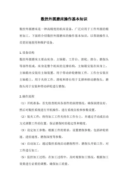
数控外圆磨床操作基本知识数控外圆磨床是一种高精度的机床设备,广泛应用于工件外圆的精密加工。
下面将介绍数控外圆磨床的操作基本知识,以帮助操作人员更好地使用和维护设备。
1. 设备结构数控外圆磨床主要由床身、主轴箱、工作台、滑枕、滑台、磨削头等部件组成。
床身是整个机床的支撑结构,主轴箱安装在床身上,主轴箱内安装有主轴装置,用于带动砂轮磨削工件。
工作台安装在主轴箱上,用于夹持工件。
滑枕和滑台用于支撑和移动磨削头,磨削头用于安装和带动砂轮进行磨削。
2. 操作流程(1)开机准备:首先检查机床各部件的润滑情况,确保润滑良好。
然后对数控系统进行开机操作,进行系统自检和参数设置。
(2)装夹工件:将待加工工件夹持在工作台上,并通过手动或自动方式调整工件的位置,保证磨削时的稳定性和精度。
(3)设定加工参数:根据工件的要求,设置磨削参数,包括砂轮转速、进给速度、磨削深度等参数。
(4)启动加工:通过数控系统启动磨削程序,磨削头开始工作,对工件进行加工。
(5)监控加工过程:在加工过程中,及时观察加工情况,根据加工效果进行必要的调整,确保加工质量。
(6)结束加工:加工完成后,停止磨削头的工作,将工件取下并进行检查,确认加工质量符合要求。
3. 安全注意事项在操作数控外圆磨床时,需要注意以下安全事项:(1)戴好劳保用品,保护好眼睛和手部。
(2)严格按照操作规程进行操作,不得擅自改动加工参数。
(3)禁止在机床运行时触摸旋转部件,以免发生意外。
(4)定期检查机床的润滑情况和各部件的运行状态,确保设备正常运转。
(5)加工过程中,严禁将手部或其他物品伸入磨削区域,以免造成伤害。
4. 维护保养为了确保数控外圆磨床的正常运转和长期稳定性,需要定期进行维护保养工作。
(1)定期清洁机床表面和各部件,保持机床清洁。
(2)检查机床的润滑系统,添加润滑油,确保各部件的润滑良好。
(3)定期检查数控系统,及时更新系统软件,保证系统正常运行。
(4)定期检查磨削头和砂轮,更换磨损严重的部件,保证加工精度和质量。

D磨床操作手册Prepared on 21 November 2021目录对你安全非常重要的通知 (4)对于磨床操作的警告 (5)对于磨床维护的警告 (6)关于手册 (7)关于磨床自动和处理的能力 (8)840D-HD 403/425磨床技术参数 (9)第一章绪论序言 (10)后床身 (10)前床身 (10)独立卡规床身 (10)计算机数控轴 (11)Z-轴(砂轮滑架) (11)X-轴(砂轮滑架支座) (11)U-轴 (11)Y-轴 (12)A-轴 (12)S2-轴 (12)S1-轴 (12)V-轴 (12)C-轴 (12)E-轴 (13)Q-轴 (13)A1-轴 (13)A2-轴 (13)磨床自动化介绍CNC(Computer Numerical Control) (14)PLC(Programmable Logic Controller) (14)PC(Personal Computer) (14)打印 (14)POMINI磨床的设计理念 (14)第二章操作画面主菜单 (15)目录 (17)报告 (18)下支轧辊 (17)现在轧辊 (18)配对轧辊检查 (19)轧辊/磨床 (20)轧辊参数 (20)轧辊公差和涡流/超声波探伤临界值 (22)磨床 (24)循环显示 (25)循环选择 (28)循环选择2(设置) (30)从中心退回选择 (32)循环顺序 (34)磨削参数 (35)磨削文件帮助 (37)磨削文件范例 (38)掏沟 (39)缺陷切除控制 (40)倒角参数 (41)砂轮修整 (42)手动校准 (43)维护 (44)程序选择 (45)第三章操作控制面板控制盘(见操作手册71页) (46)CNC (Computer Numerical Control)操作盘 (49)第四章磨床操作. 供电顺序 (52). 对询问的回答 (53). 磨床临时停止 (54). 供电关闭顺序 (55). 独立卡规收回顺序 (56). 磨床操作程序 (57). 磨削循环 (58).1. 磨削步骤(步骤代号1到10) (58).2. 砂轮自动接近 (59).3. 砂轮手动接近 (59).4. 短行程磨削 (59).5. 在中心返回 (59).6. 连续进给 (60).7. 端部进给 (60).8. 负载控制 (60).9. 砂轮超载返回 (60).10. 砂轮探头重新校准 (60).11. 初始校正(磨削顺序代号11) (61).12. 最终校准(磨削顺序代号12) (61). 轧辊偏心 (61). 不停止磨削循环的辊形测量 (62).14. 直径测量 (62). 不停止磨削循环的直径测量 (62).15. 磨削阶段代码 (63).16. 循环结束(顺序代码40) (63). 修整循环 (64). 掏沟循环 (65). 砂轮探头校准 (66). 清洁循环 (67). 倒角循环 (68). 辊形记录 (69). 轧辊手动校准 (70). 直径测量 (71). 卡规设置 (72). 涡流探伤测量 (73)对你安全非常重要的通知●如果发现有任何异常噪音和振动,应紧急停止磨床并断开主开关;●为断开砂轮电机的电气控制回路,磨床提供了一个安全电气开关。

摘要数控技术发展飞速的今天,数控技术在现代制造业发挥越来越重要的作用,数控机床是数控制造业的核心,本文主要介绍了对数控车床的电气系统设计的过程。
本设计以CK6140车床为载体,对其数控电气系统经行详细设计。
其内容包括强电设计、弱电设计、PLC输入输出及接口设计,本设计选用西门子808D数控系统。
最后绘制出整个机床的电气系统原理图等。
本设计给出了整个机床的原理图绘制过程,重点部分模块化,较详细地介绍了各个部分的功能及用途。
分为 380V强电回路,控制回路,PLC输入输出控制,主轴驱动模块和进给伺服驱动模块,并介绍了相关的电气知识。
通过本设计说明书可以基本上掌握数控车床的电气原理,以及基本的电气常识,使读者无论是从整体上还是各个模块中都能够了解到数控车床相关的一系列电气知识。
关键词:数控系统;数控车床;PLC控制1ABSTRACTThe numerical controls that the technique development fast today, the numerical controls technique at the modern manufacturing industry exertive more and more importance function, numerical control tool machine is number control a manufacturing industry of core, this text mainly introduced logarithms to control the processed that the electricity system of lather design.The design CK6140 lathe as the carrier, the detailed design of the its NC electrical system through the line. its contents includes a strong electrically design, weakness design, PLC importation output and Interface design. The design uses a Siemens 808D CNC system. Finally, to map out the whole machine electrical system schematic. This principle diagram which designs to the whole tool machine draws process and the point parts of mold piece turn and compared to in detail introduce each function and use of part. Is divided into the 380 Vs strong electricity back track, control back track, the PLC importation outputs a control, the principal axis drives a mold piece and enters to servo drive a mold piece, and introduced related electronic knowledge.Through this design system can basically control numerical control the electricity principle of lather, and basic electronic common sense, make the reader regardless can understand numerical control the lather related series of electricity knowledge from wholly the top still each mold piece.Key Words:NC system; NC lathe; PLC control2目录摘要------------------------------------------------------------------------------------------------------- 1 ABSTRACT ------------------------------------------------------------------------------------------- 2目录------------------------------------------------------------------------------------------------------ 3第一章绪论----------------------------------------------------------------------------------------- 61.1前言 ------------------------------------------------------------------------------------------ 61.2国外数控系统的发展趋势 ------------------------------------------------------------- 61.2.1新一代数控系统采用开放式体系结构 ------------------------------------ 61.2.2新一代数控系统控制性能大大提高---------------------------------------- 71.2.3数控系统向软数控方向发展 ------------------------------------------------- 71.3我国数控技术的发展-------------------------------------------------------------------- 81.4CK6140数控车床主简介 ---------------------------------------------------------------- 9第二章西门子808D数控车床系统 --------------------------------------------------------- 112.1 西门子808D系统简介 --------------------------------------------------------------- 112.2人机界面 ---------------------------------------------------------------------------------- 132.3进给系统 ---------------------------------------------------------------------------------- 132.4 主轴驱动系统--------------------------------------------------------------------------- 132.5刀架控制系统 --------------------------------------------------------------------------- 142.6电柜设计及电源选用------------------------------------------------------------------ 142.6.1在设计电柜时应注意以下事项:----------------------------------------- 142.6.2 24VDC电源选用---------------------------------------------------------------- 152.7数控系统各部分的连接及接口 ----------------------------------------------------- 152.7.1系统的接线---------------------------------------------------------------------- 152.7.2 接口布置 ------------------------------------------------------------------------ 15第三章CK6140数控车床的基本组成和工作原理 --------------------------------------- 173.1数控车床组成 --------------------------------------------------------------------------- 173.2数控车床工作原理 --------------------------------------------------------------------- 193.3 CK6140数控车床运动分析 ---------------------------------------------------------- 2033.4 CK6140数控车床电气系统简述 ---------------------------------------------------- 21第四章CK6140数控车床硬件系统设计及元件选型------------------------------------ 254.1主轴驱动系统 --------------------------------------------------------------------------- 254.1.1主轴电动机---------------------------------------------------------------------- 254.1.2主轴电动机选型 --------------------------------------------------------------- 254.2机床进给伺服系统 --------------------------------------------------------------------- 264.2.1 CK6140数控车床对伺服驱动进给系统的要求------------------------ 274.2.2 伺服电机的选型--------------------------------------------------------------- 284.3控制电路原理图设计------------------------------------------------------------------ 314.3.1 380V系统强电控制回路----------------------------------------------------- 314.3.2电源回路 ------------------------------------------------------------------------- 334.4常用电器元件的选型------------------------------------------------------------------ 344.4.1低压电器选型的一般原则 -------------------------------------------------- 344.4.2断路器的选型------------------------------------------------------------------- 344.4.3电动机保护用自动开关的选型 -------------------------------------------- 354.4.4 熔断器选型 --------------------------------------------------------------------- 354.4.5接触器的选型------------------------------------------------------------------- 354.4.6热继电器的选型 --------------------------------------------------------------- 364.4.7中间继电器---------------------------------------------------------------------- 364.5 CK6140数控车床控制面板 ---------------------------------------------------------- 37第五章PLC设计及参数设置------------------------------------------------------------------- 395.1 PLC的基本结构及工作原理 --------------------------------------------------------- 395.2 PLC与CNC机床的联接方式 -------------------------------------------------------- 405.3 CNC加工代码在PLC上的实现方法----------------------------------------------- 415.3.1 T功能代码的实现方法------------------------------------------------------- 425.3.2 M功能代码实现方法--------------------------------------------------------- 425.4 PLC程序的模块化设计---------------------------------------------------------------- 425.5 PLC输入输出地址分配---------------------------------------------------------------- 425.6参数设置 ---------------------------------------------------------------------------------- 4445.6.1 PLC参数设置-------------------------------------------------------------------- 445.6.2机床参数设置------------------------------------------------------------------- 45第六章结论--------------------------------------------------------------------------------------- 47致谢 -------------------------------------------------------------------------------------------------- 48参考文献 --------------------------------------------------------------------------------------------- 495第一章绪论1.1前言装备工业的技术水平和现代化程度决定着整个国民经济的水平和现代化程度,机床制造业是一个国家的基本装备工业,是工业生产的技术基础,数控技术在给机床制造业带来显著经济效益及广阔发展前景的同时,也是发展新兴高新技术产业和尖端工业(如信息技术及其产业、航空、航天等国防工业产业)的使能技术和最基本的装备,因此它已成为衡量一个国家制造业水平的重要标志之一。
沈阳机床808D安全指导书1、变压器、电机及带有高压接线端子等部位不要去触摸,以免遭到电击的危险。
2、千万不要用湿手去触摸开关,否则会引起电击。
3、在操作机床前,必须清楚机床上的各种按钮开关的作用,否则不准乱按开关。
4、要有足够的工作空间,以避免产生危险。
5、应采用单独的接地线,其长度应尽可能短。
6、操作者应非常熟悉急停按钮开关的位置,以便需要时,无须寻找就会按到它。
7、机床出现故障或处于危机状态时,应首先按下急停按钮,然后断开总电源开关:故障排除之前不准通电。
8、停电时应马上断开总电源开关。
9、水或油能使地面打滑而造成危险,为了防止出现意外的事故,工作地面应保持洁净干燥。
10、不要弄脏、刮伤或弄掉警告标牌。
如果标牌.上的字迹已变得模糊不清或遗失了,应向厂方订购新的标牌。
在订购时要标清标牌的件号。
11、使用推荐的润滑油和油脂或认可的等同性能的油。
12、凡是绝缘皮损坏的线缆、软线或导线都会产生电流漫漏和电击。
所以,在接通电源前,应进行检查。
13、为机床所配置的送电开关的线缆和主线路开关用的线缆必须按电路图中规定的横截面,以满足电力的要求。
14、确保不小于每一一相导线截面积的保护连接线牢靠地接到机床的PE端子。
15、接电源前应仔细检查电气系统是否完好,注意电动机有无受潮。
16、应将油箱的油灌到油标处。
在必要时应进行检查并重新注油。
17、对于润滑点,油的种类和相应的油位。
请参见润滑标牌。
18、各个开关都应灵活、平滑好用。
要检查它们的动作情况。
19、应穿防油的绝缘鞋,穿工作服和配带其它安全防护用品。
20、检查有无线缆. 接插件脱落、着地,空气开关是否闭合。
数控车床电气使用说明书(华中HNC-808A-T系统)(HST伺服刀架)沈阳巨浪特种机床科技有限公司注意事项1.本机床的操作者应具有中专及以上文化程度,且经过机床制造厂家的专门培训。
2.机床在使用前,操作人员必须认真阅读机床使用说明书、数控系统操作说明书等技术资料,特别要详细了解关于吊运、安装、调整、操作方面的安全说明。
在对机床的有关情况还未了解之前,不能吊运安装、调整、操作机床。
3.本机床基本配置不含开门断电功能,操作者在机床切削过程中应注意关严安全门,禁止在开门的条件下加工工件,因为存在着刀片夹持不牢、由于操作等原因造成的刀具与工件意外撞车产生金属碎片、切屑及冷却液被旋转刀具带动甩出等多种可能因素,一旦发生将可能造飞出物击伤人员的危险。
左右侧门仅供机床维修时使用,机床运行时严禁打开。
4.本说明书编写时,已符合当时机床实物状况。
由于设计改进引起的修改内容,对出厂后的机床的用户恕不通知。
目录1 安全说明2 机床通电前的准备工作3 机床坐标系的设定4 机床的操作说明5 机床电气原理图1 安全说明在操作机床和进行日常维修之前,操作人员必须仔细阅读本说明书,以对机床安全措施和要求有所了解。
并遵守相关的安全预防措施。
1.1 安全总则1.1.1 不要用湿手接触任何开关以免触电。
机床的X轴伺服电机位置的防护罩、立柱背后接线盒、机床变压器柜、电气柜门等处贴有闪电标牌,表示这些部位有高电压用电器或电气元件,操作者在接近这些部位或打开维修时应格外小心,以免触电。
1.1.2 应十分熟悉急停按钮的位置,操作面板上有一个带红色蘑菇头形状的急停按钮,在发生意外撞车及其它紧急情况时应迅速地就近按下急停按钮,切断动力电源,机床会立即停车,避免发生更严重的损坏。
1.1.3 全面阅读机床说明书及电气原理图,以便熟悉各项功能和对应键的操作方法。
1.1.4 不要随意按压操作按钮及行程开关。
不要改动限位开关的位置,未和制造厂联系,不得自行调整丝杠螺母、丝杠轴承预紧状态及丝杠预拉伸量,不得松动和擅自拆装联轴器,以免影响传动精度。
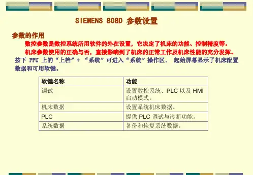
SIEMENS 808D调试(山东威达加工中心)1.接口:(1)数字量输入接口3个,分别为X100,X101,X102(此接口为10针插座)(2)数字量输出接口2个,分别为X200,X201(此接口为10针插座)(3)快速输入输出接口1个,为X21(此接口为10针插座)(4)分布式输入输出接口2个,分别为X301,X302(此接口为50针排线插座)(5)手轮输入接口X10(此接口为10针插座)(6)主轴编码器接口X60(此接口为15孔DB头插座)(7)主轴模拟量输出接口X54(此接口为9孔DB头插座)(8)RS232通信接口X2(此接口为9针DB头插座)(9)连接驱动器接口3个,分别为X(X51)/Y(X52)/Z(X53)(此接口为15针DB 头插座)(10)连接操作面板的USB接口1个(11)DC24V接口1个(为4针接口)2.各接口信号:(1)数字量输入接口X100、X101、X102(输入24V有效)(4)分布式输入输出:X301、X302分布式输入输出接口的引脚分布图如下:数字量输入接法:数字量输出接法:(5)手轮输入信号X1010 -2B 手轮2,B相脉冲负(7)模拟量主轴接口X54:(8)主轴编码器X60:3.参数:按【上档】+【系统/诊断】或【ALT】+【N】键进入,制造商级别密码为SUNRISE。
(3)通道机床数据(20000-28999):(4)轴机床数据(30000-38999):(5)一般设定数据(41000-41999):4.PLC:(1)PLC状态列表:查看输入输出信号及各寄存器数据状态,同时可以修改某些寄存器数据。
(2)PLC程序:可以查看主程序及各子程序。
(3)PLC报警编辑:可以编辑各PLC报警内容。
5.其他:。
Training manualSinumerik 808D ADVANCED Commissioning Guide Version 2013-09s NotesCommissioning Guide Page 2 808D ADVANCED Turning and Milling808D ADVANCED Turning and MillingPage 3 Commissioning GuidesThe warranty is connected to the product serial number of the808D ADVANCED.You can find the product serial number:On the back of PPU system hardware.Picture 1product serialnumberOr on the display.After switch-on, press the “Shift” and “Alarm” keys together.Then press the “Extension” buttonThis will enter into the system area.(see picture 1)Press softkey to enter the screen of service axes ( see picture 2).Press softkey to enter the screen of version data ( see picture 3).You can find the serial number information which needs to be registeredstarting with the letters “SZV”.For any question about ”SZV” serial number and the steps to register ,Please contact the Siemens Technical Support & Service Hotline:+86 4008104288Picture 2Picture 3Product identification / SINUMERIK 808D ADVANCEDNotesCommissioning Guide Page 4 808D ADVANCED Turning and Milling808D ADVANCED Turning and Milling Page 5 Commissioning GuideNotesCommissioning Guide Page 6 808D ADVANCED Turning and Milling808D ADVANCED Turning and Milling Page 7 Commissioning GuideCommissioning Guide Page 8 808D ADVANCED Turning and MillingIn the following technical drawing the mounting dimensions for the PPU and the MCP are shown.You must provide sufficient space (recommended distance: 80 mm) between the maintenance door and the cabinet wall for replacing the For further components refer to :- Commissioning manual page 21Spindle encoderUSB stickHandwheels+24V DC power supply808D MCPMotor Motor MotorSINUMERIK808D ADVANCED PPUPC/PG Spindle motorInverter or servo spindle driveNotes :1. PC and memory stick is not included in scope of delivery.2. "USB", "Handwheel","24V DC power supply", "Emergency stop button", "Inverter or servo spindle drive", "Spindle encoder" are also not included in scope of delivery.Emergency stop buttonFactory NetworkSINAMICS V70 In total 14 clamps are provided together with the delivery of PPU 1. 8 clamps for mounting PPU. 2. 6 clamps for mounting MCP.Terminator808D ADVANCED Turning and Milling Page 9 Commissioning GuideBBAAX10 NCMCPThe clamps are located at the positions indicated with the black triangles. The black triangles can be seen in the above picture highlighted with red circles.PPU = P anel P rocessing U nit MCP = M achine C ontrol P anel808D PPU808D MCPCommissioning Guide Page 10 808D ADVANCED Turning and MillingThe clamps are located at the positions indicated with the black triangles. The black triangles can be seen in the following picture with red circles.MCPMCPVertical MCP without handwheelVertical MCP with ingrate handwheel808D PPU808D MCPThe cut-out dimensions for the 808D ADVANCED vertical PPU and Cut-out dimensionsElectrical cabinet> 20 mm> 20 mm> 20 mm> 20 mm> 100 m m> 100 m mSINAMICS V70 Servo driveSINAMICS V70 Servo driveSINAMICS V70 Servo drive For further information refer to :-Circuit breaker (optional) Switches off the power supply to protect thenetwork when overcurrent occursLine filter (optional)Protects the network from harmonic load and/or interference voltages.Braking resistor (optional) Absorb excess regenerative energy in the DC link when the capacity of the internal braking resistor is insufficientSINUMERIK 808D ADVANCEDEmergency stop button (optional)Stops a motor in emergency cases.24 V DC power supplyBrake cableEncoder cableP o w e r c a b l e3 phase 380V AC line supplyL1 l2 l3SIMOTICS S-1FL6 servomotorSINIMICS V70 servodriveAccessories not included in the scope of deliveryConnections not necessarily requiredShielding layerDrive bus terminator14 311 13414 126 47Legend Interface CommentMCP Back X10USB interface, for connection with thePPUBB AAX10 NCMCP back1NoteConnect USB cable between X30 on PPU and X10 on MCP.These 4 aspects should be considered during selection of 24V DC supply calculation base on name plate. Consideration of redundancy coefficient base on regulation of OEMMCP backX10 NCE-stop Limit X+ Limit X - Limit Y+ Limit Y- Limit Z+ Limit Z- Ref X M1 2 3 45 6 7 8 9 10X100+ 24VMillingDigital inputsDistribution I/O board For the connection of distribution I/O on X301must be configured. MLFB for distribution I/ORef Y Ref ZMagazine countMagazine at spindle position Magazine at original position Magazine at release position Magazine at clamp position M1 2 3 4 5 6 7 8 9 10X101+24VDisk magazine: magazine rotating CW Disk magazine: magazine rotating CCW Disk magazine: magazine in spindle position Disk magazine: magazine in original position Disk magazine: spindle tool releaseHandheld unit active M1 2 3 4 5 6 7 8 910X201Coolant level lowCooling motor overload Lubrication level lowLubrication motor overload M1 2 3 4 5 6 7 8 9 10X102+24VWorking lampChip remover forward Chip remover reverse Cooling pump Lubrication pump Safety door open M1 2 3 4 5 6 7 8 910X200Turning Digital inputs11 - Handheld unit: axis X selected 13 - Handheld unit: axis Z selected 14 - Handheld unit: axis 4th selected 15 - Handheld unit: INC X1 16 - Handheld unit: INC X10 17 - Handheld unit: INC X100 18 - Handheld unit: enabledMFor the connection of distribution I/O on X301must be configured. MLFB for distribution I/O X301 Distributed I/OE-stop Limit X+ Limit X -Limit Z+ Limit Z- Ref X M1 2 3 4 56 7 8 9 10X100+ 24VTurret motor overload Reserved for other turretChuck openCoolant level lowCooling motor overload Lubrication level lowLubricating motor overload M1 2 3 4 5 6 7 8 9 10X102+24VWork lampTailstock advancing Tailstock retracting Coolant pump Lubrication pump Chuck output 1 Chuck output 2 M1 2 3 4 5 6 7 8 910X200+24VTurret motor CW Turret motor CCWReserved for other turret Reserved for other turret Gear change: low Gear change: highHandheld unit active M1 2 3 4 5 6 7 8 910X201Ref. Z T1 T2 T3 T4 T5 T6 M 12345678910X101Spindle/ inverter motor(black)blackblack blackSpindle/ inverter motorSINUMERIK 808D ADVANCED PPUSINUMERIK 808D ADVANCED PPUIn some cases, an extra language has to be selected. Double-click the “Setup.exe”During the installation various dialogue boxes will appear. The dialogue boxes should be acknowledged and where necessary installation data should be entered and confirmed.Installing all the software packages will take approximately 30 minutes. When the installation has finished icons will be placed on the desk top.Activate the PLC connection setting in 808D (password set to “sunrise”) Double click highlighted area.The connection is now established, this is shown by a green box.Status description on front LED’s of PPUIf the drive data is different from the 808D backup data, a data synchroni-zation is required for synchronizing the drive data files between the NCStatus description on SINAMICS V70 Item DescriptionStatus LED’s indicator colour RDY-GreenStatus on power up with incremental encoderStatus on power up with absolute encoderType in “SUNRISE”Type in time and date using the key-board and the andWhen the PPU shows the followingTo accept the selection.On power up of the control the current alarms 4060 and 400006 can be acknowledged with the “Reset” and “Alarm cancel” buttons Type in SUNRISESelect the language withYou can load a new system language or update an existing language on Siemens will provide each language in the form of an archive file.“Option”, a new licence key Press the SKTo active an “Option”, enter Press the SKFunctionvertical =0 - horizontal=1Spindle braking timeMax Tool number in magazineLubrication intervalLubrication durationTool magazine:spindle poisoning angleTool magazine: Preparation position of Z axes for tool changeTool magazine: Tool changing posion of Z axesTool magazine: velocity of Z axis, Go to tool change preparation positionTool magazinevelocity of Z axis, back to tool change preparation positionRange Functionality- flat bed=0 - inclined bed = 15~200 Spindle braking time4, 6 Max Tool number in turret.(for tool amount >6, PLC to beprogrammed by customer them-selves)5~30 HED turret: Tool clamping time for 30~200 HED turret: Time monitoring fortool change5~300 Lubrication interval12~2000 Lubrication durationPLC MD is to be adapted to suit the machine To continue press the SKChanges will be activated MD set to default value MD set to previous valueIt may be that the machine tool builder requires further PLC functionality, if this is required the PLC has to be modified.To install PLC programming tool, follow the information in :- PLC Subroutines manual page 8 (install PLC programming tool) To make a connection to the PPU, press SK Then follow the information in:-PLC Subroutines manual page 18To continue press the SKFirst the “Sample PLC blocks” should be uploaded to the PC, then the modifications can be made to achieve the required functionality. Once this has been completed, the PLC should be put into stop and the modified PLC should be downloaded into the PPU. The PLC must then bePLC Subroutines manual page 25To continue press the SK All I/O status must be checked with the electrical drawing using the following SK’s. The status is shown on the right hand side as shown Vertical SK’s allow you to select digital inputs or outputs and selection ofTo continue press the SKChoose digital inputChoose digital outputChoose the digital O/I addresses of Byte -Choose the digital O/I addresses of Byte +You can edit the PLC user alarm text either directly on the HMI, or off line by transferring the file using a USB stick.Vertical SK’s allow you to import and export the text file from the HMI, and SK that that allows the text file to be directly edited on the HMI.To continue press the SKImport the backup alarm text into the PPU Edit the alarm textExport the finished alarm text from the PPU Set “address data” for each axis: Remove drive bus cable from terminal X10 Press M repeatedly (until “FUnC” is displayed) Press ▼(until “Addr” is displayed) Press ▼(until desired address is displayed) Press ▼(until “SAvE” is displayed) Screen will go blank (wait about 20sec) (Screen will display “S OFF” or a fault code) Replace drive bus cable to terminal X10 Drives must now be powered off/onStarts the configuring of the V70 drive.Starts the configuration of spindle motor motors on the M3 Drive BusSelect the motor from the table that matches the motor name plate.Starts the configuring of the motor data to the drive All axis motors are indentifiedStarts the configuration of each unidentified spindleAll axis and spindle motors are indentified.You can edit the spindle machine data for the required axis.Vertical SK’s allow you to edit, activate or set as default value.MD set to default valueMD set to previous valueTo continue press the SK To continue press the SKFollowed by creating the drive dataYou can edit the axis machine data and the for the required axis. Vertical SK’s allow you to edit, activate or set as defaultUsed to select the axis (X or Z turn or X, Y, or Z mill)Changes will be activatedMD set to default valueMD set to previous valueAn axis can be referenced You can edit the spindle machine data required.Vertical SK’s allow you to edit, activate or set as defaultUsed to select the axis (X or Z turn or X, Y, or Z mill)Changes will be activatedMD set to default valueMD set to previous valueTest spindle in MDA modeVertical SK allows you to, create the “series start-up archive” press SK Create production archiveWhen creating the productionbackup, store archive to USB You can edit the axis machine data for the required axis.Vertical SK’s allow you to edit, activate or set as defaultUsed to select the axis (X or Z turn or X, Y, or Z mill)Changes will be activatedMD set to default valueMD set to previous valueYou can edit the axis machine data for the required axis.Vertical SK’s allow you to edit, activate or set as defaultUsed to select the axis (X or Z turn or X, Y, or Z mill)Changes will be activatedMD set to default valueMD set to previous value You can edit the axis machine data for the required axis.Vertical SK’s allow you to edit, activate or set as defaultUsed to select the axis (X or Z turn or X, Y, or Z mill)Used to enter compensation data via the HMIChanges will be activatedThere are three “Optimization2 Aggressive measurement3 Conservative measurementPress “Start Optim.” SK Select the required strategy.To continue press the SKThe following window will be shown.To continue press the BUTTON To continue press the BUTTONThe axis optimization operation process will now optimise MZ1 axis of highPress “Next” SK to continueand low frequency measurement process. (a repeat of the 8 passes asVertical SK allows you to, create the “production archive” press SK “Create Create Start-up archivearchive, store archive to USB。
外圆磨床操作方法(总1页)本页仅作为文档封面,使用时可以删除
This document is for reference only-rar21year.March
外圆磨床操作方法
1.开机后令其空转3-5分钟,之后开始检查各个系统工作情况是否正常。
2.根据要加工的工件来确定所用夹具规格,调整夹具松紧程度,使其方便装夹又牢靠。
3.调整机床:根据工件形状长度,调整合适的尾座位置,压紧尾座,把砂轮退远一定距离,装上工件,开启主轴,使工件旋转。
检查:旋转状况是否正常,夹具与机床插销接触是否合适,停下主轴检查取下工件时是否方便快捷。
4.修整砂轮:根据工件图纸修整砂轮成型面(特别注意:每次修之前一定要记得先退砂轮,退到使其进刀后都能与金刚笔头有一段距离的安全点,打进给手柄使其砂轮靠近修刀座,然后缓慢摇动刻度盘,让砂轮缓慢接触金刚笔,少量进给修整)
5.对刀:装上工件,调整砂轮位置,使其对准要加工的工件位置,为保证安全,最好退一定距离的砂轮。
进刀,缓慢接触工件进行对刀。
6.检测,加工
警惕!切削用量不可太大,一般单边不超过10丝,每次进刀加工都要退刻度盘,等砂轮接触工件后再缓慢摇刻度盘到加工指定位,否则有可能抵爆砂轮。
砂轮爆炸犹如黑炸药爆炸,切记!切记!。