光伏发电外文翻译
- 格式:doc
- 大小:48.50 KB
- 文档页数:7

外文参考文献译文及原文目录外文文献译文 (1)1.中国光伏发电的战略地位 (1)2.世界光伏产业现状和发展预测 (2)3.中国光伏发电市场和产业现状 (3)4.中国光复发电的市场预测和规划建议 (5)5.结论 (6)外文文献原文 (7)1.China's strategic position PV (7)2.The world's current situation and development of photovoltaic industryforecast (9)3.The Chinese PV market and industry statu s (10)4.China's PV market forecasting and planning proposals (13)5.Conclusions (15)外文文献译文1、中国光伏发电的战略地位1.1 中国的能源资源和可再生能源现状和预测;无论从世界还是从中国来看,常规能源都是很有限的,中国的一次能源储量远远低于世界的平均水平,大约只有世界总储量的10%。
从长远来看,可再生能源将是未来人类的主要能源来源,因此世界上多数发达国家和部分发展中国家都十分重视可再生能源对未来能源供应的重要作用。
在新的可再生能源中,光伏发电和风力发电是发展最快的,世界各国都把太阳能光伏发电的商业化开发和利用作为重要的发展方向。
根据欧洲JRC 的预测,到2030年太阳能发电将在世界电力的供应中显现其重要作用,达到10%以上,可再生能源在总能源结构中占到30%;2050 年太阳能发电将占总能耗的20%,可再生能源占到50%以上,到本世纪末太阳能发电将在能源结构中起到主导作用。
我国政府重视可再生能源技术的发展,主要有水能、风能、生物质能、太阳能、地热能和海洋能等。
我国目前可再生能源的发展现状如下:水能:我国经济可开发的水能资源量为3.9 亿千瓦,年发电量1.7 万亿千瓦时,其中5 万千瓦及以下的小水电资源量为1.25 亿千瓦。
太阳能发电外文翻译文献(文档含中英文对照即英文原文和中文翻译)Design of a Lead-Acid Battery Charging and Protecting IC in Photovoltaic SystemZENG De-you,LING Chao-dong,LI Guo-gang1.IntroductionSolar energy as an inexhaustible, inexhaustible source of energy more and more attention. Solar power has become popular in many countries and regions, solar lighting has also been put into use in many cities in China. As a key part of the solar lighting, battery charging and protection is particularly important. Sealed maintenance-free lead-acid battery has a sealed, leak-free, pollution-free, maintenance-free, low-cost, reliable power supply during the entire life of the battery voltage is stable and no maintenance, the need for uninterrupted for the various typesof has wide application in power electronic equipment, and portable instrumentation. Appropriate float voltage, in normal use (to prevent over-discharge, overcharge, over-current), maintenance-free lead-acid battery float life of up to 12 ~ 16 years float voltage deviation of 5% shorten the life of 1/2. Thus, the charge has a major impact on this type of battery life. Photovoltaic, battery does not need regular maintenance, the correct charge and reasonable protection, can effectively extend battery life. Charging and protection IC is the separation of the occupied area and the peripheral circuit complexity. Currently, the market has not yet real, charged with the protection function is integrated on a single chip. For this problem, design a set of battery charging and protection functions in one IC is very necessary.2.System design and considerationsThe system mainly includes two parts: the battery charger module and the protection module. Of great significance for the battery as standby power use of the occasion, It can ensure that the external power supply to the battery-powered, but also in the battery overcharge, over-current and an external power supply is disconnected the battery is to put the state to provide protection, the charge and protection rolled into one to make the circuit to simplify and reduce valuable product waste of resources. Figure 1 is a specific application of this Ic in the photovoltaic power generation system, but also the source of this design.Figure1 Photovoltaic circuit system block diagramMaintenance-free lead-acid battery life is usually the cycle life and float life factors affecting the life of the battery charge rate, discharge rate, and float voltage. Some manufacturers said that if the overcharge protection circuit, the charging rate can be achieved even more than 2C (C is the rated capacity of the battery), battery manufacturers recommend charging rate of C/20 ~ C/3. Battery voltage and temperature, the temperature is increased by 1 °C, single cell battery voltage drops 4 mV , negative temperature coefficient of -4 mV / ° C means that the battery float voltage. Ordinary charger for the best working condition at 25 °C; charge less than the ambient temperature of 0 °C; at 45 °C may shorten the battery life due to severe overcharge. To make the battery to extend the working life, have a certain solar battery array Charge controllercontroller Dischargecontroller DC load accumulatorunderstanding and analysis of the working status of the battery, in order to achieve the purpose of protection of the battery. Battery, there are four states: normal state, over-current state over the state of charge, over discharge state. However, due to the impact of the different discharge current over-capacity and lifetime of the battery is not the same, so the battery over discharge current detection should be treated separately. When the battery is charging the state a long time, would severely reduce the capacity of the battery and shorten battery life. When the battery is the time of discharge status exceeds the allotted time, the battery, the battery voltage is too low may not be able to recharge, making the battery life is lower. Based on the above, the charge on the life of maintenance-free lead-acid batteries have a significant impact, while the battery is always in good working condition, battery protection circuit must be able to detect the normal working condition of the battery and make the action the battery can never normal working state back to normal operation, in order to achieve the protection of the battery.3.Units modular design3.1The charging moduleChip, charging module block diagram shown in Figure 2. The circuitry includes current limiting, current sensing comparator, reference voltage source, under-voltage detection circuit, voltage sampling circuit and logic control circuit.Figure2 Charging module block diagramdriverV oltage amplifierV oltage sampling comparatorStart amplifierState level control Charging indicator Logicalmodule Undervoltage detection circuitR- powerCurrent sampling comparator Limitingamplifier Power indicatorThe module contains a stand-alone limiting amplifier and voltage control circuit, it can control off-chip drive, 20 ~30 mA, provided by the drive output current can directly drive an external series of adjustment tube, so as to adjust the charger output voltage and current . V oltage and current detection comparator detects the battery charge status, and control the state of the input signal of the logic circuit. When the battery voltage or current is too low, the charge to start the comparator control the charging. Appliances into the trickle charge state when the cut-off of the drive, the comparator can output about 20 mA into the trickle charge current. Thus, when the battery short-circuit or reverse, the charger can only charge a small current, to avoid damage to the battery charging current is too large. This module constitutes a charging circuit charging process is divided into two charging status: high-current constant-current charge state, high-voltage charge status and low-voltage constant voltage floating state. The charging process from the constant current charging status, the constant charging current of the charger output in this state. And the charger continuously monitors the voltage across the battery pack, the battery power has been restored to 70% to 90% of the released capacity when the battery voltage reaches the switching voltage to charge conversion voltage Vsam charger moves to the state of charge. In this state, the charger output voltage is increased to overcharge pressure V oc is due to the charger output voltage remains constant, so the charging current is a continuous decline. Current down to charge and suspend the current Ioct, the battery capacity has reached 100% of rated capacity, the charger output voltage drops to a lower float voltage VF.3.2 Protection ModuleChip block diagram of the internal protection circuit shown in Figure 3. The circuit includes control logic circuit, sampling circuit, overcharge detection circuit, over-discharge detection comparator, overcurrent detection comparator, load short-circuit detection circuit, level-shifting circuit and reference circuit (BGR).Figure3 Block diagram of battery protectionThis module constitutes a protection circuit shown in Figure 4. Under the chip supply voltage within the normal scope of work, and the VM pin voltage at the overcurrent detection voltage, the battery is in normal operation, the charge and discharge control of the chip high power end of the CO and DO are level, when the chip is in normal working mode. Larger when the battery discharge current will cause voltage rise of the VM pin at the VM pin voltage at above the current detection voltage Viov, then the battery is the current status, if this state to maintain the tiov overcurrent delay time, the chip ban on battery discharge, then the charge to control the end of CO is high, the discharge control side DO is low, the chip is in the current mode, general in order to play on the battery safer and more reasonable protection, the chip will battery over-discharge current to take over the discharge current delay time protection. The general rule is that the over-discharge current is larger, over the shorter the discharge current delay time. Above Overcharge detection voltage, the chip supply voltage (Vdd> Vcu), the battery is in overcharge state, this state is to maintain the corresponding overcharge delay time tcu chip will be prohibited from charging the battery, then discharge control end DO is high, and charging control terminal CO is low, the chip is in charging mode. When the supply voltage of the chip under the overdischarge detection voltage (Vdd <Vdl,), then the battery is discharged state, this state remains the overdischarge delay time tdl chip will be prohibited to discharge the battery at this time The charge control side CO is high, while the discharge control terminal DO is low, the chip is in discharge mode. Sampling circuitOver discharge detection comparatorControl logic circuit Level conversion circuit Overcharge detection comparator Over-current detection comparator2 Over-current detection comparator1Over-current detection circuitLoad short detection circuitFigure4 Protection circuit application schematic diagram4.Circuit DesignTwo charge protection module structure diagram, the circuit can be divided into four parts: the power detection circuit (under-voltage detection circuit), part of the bias circuit (sampling circuit, the reference circuit and bias circuit), the comparator (including the overcharge detection /overdischarge detection comparator, over-current detection and load short-circuit detection circuit) and the logic control part.This paper describes the under-voltage detection circuit (Figure 5), and gives the bandgap reference circuit (Figure 6).Figure5 Under-voltage detection circuitProtectionmoduleBiasing circuit Reference circuit Bleeder circuit difference amplifier Output circuitAmplifierAmplifierFigure6 A reference power supply circuit diagramBattery charging, voltage stability is particularly important, undervoltage, overvoltage protection is essential, therefore integrated overvoltage, undervoltage protection circuit inside the chip, to improve power supply reliability and security. And protection circuit design should be simple, practical, here designed a CMOS process, the undervoltage protection circuit, this simple circuit structure, process and easy to implement and can be used as high-voltage power integrated circuits and other power protection circuit.Undervoltage protection circuit schematic shown in Figure 5, a total of five components: the bias circuit, reference voltage, the voltage divider circuit, differential amplifier, the output circuit. The circuit supply voltage is 10V; the M0, M1, M2, R0 is the offset portion of the circuit to provide bias to the post-stage circuit, the resistance, Ro, determine the circuit's operating point, the M0, M1, M2 form a current mirror; R1 M14 is the feedback loop of the undervoltage signal; the rest of the M3, M4 and M5, M6, M7, M8, M9, M10, M11, M12, M13, M14, composed of four amplification comparator; M15, DO, a reference voltage, the comparator input with the inverting input is fixed (V+), partial pressure of the resistance R1, R2, R3, the input to the inverting input of the comparator, when the normal working of the power supply voltage, the inverting terminal of the voltage detection is lost to the inverting terminal voltage of the comparator is greater than V+. Comparator output is low, M14 cutoff, feedback circuit does not work; undervoltage occurs, the voltage divider of R1, R2, R3, reaction is more sensitive, lost to the inverting input voltage is less than V when the resistor divider, the comparator the output voltage is high, this signal will be M14 open, the voltage across R into M at both ends of the saturation voltage close to 0V, thereby further driving down the R1> R2, the partial pressure of the output voltage, the formation of the undervoltage positive feedback. Output, undervoltage lockout, and plays a protective role.5. Simulation results and analysisThe design of the circuit in CSMC 0.6 μm in digital CMOS process simulation and analysis of the circuit. In the overall simulation of the circuit, the main observation is that the protection module on the battery charge and discharge process by monitoring Vdd potential and Vm potential leaving chip CO side and DO-side changes accordingly. The simulation waveform diagram shown in Figure 7, the overall protection module with the battery voltage changes from the usual mode conversion into overcharge mode, and then return to normal working mode, and then into the discharge mode, and finally back to normal working mode. As the design in the early stages of the various parameters to be optimized, but to provide a preliminary simulation results.Figure7 Overvoltage and under-voltage protection circuit simulation waveform6.ConclusionDesigned a set of battery charging and protection functions in one IC. This design not only can reduce the product, they can reduce the peripheral circuit components. The circuit uses the low-power design. This project is underway to design optimization stage, a complete simulation can not meet the requirements, but also need to optimize the design of each module circuit.光伏系统中蓄电池的充电保护IC电路设计曾德友,凌朝东,李国刚1.引言太阳能作为一种取之不尽、用之不竭的能源越来越受到重视。
太阳能行业专业术语中英文对照汇总1. 太阳能发电系统 Solar Power Generation System2. 光伏板 Photovoltaic Panel3. 太阳能电池 Solar Cell4. 太阳辐射 Solar Radiation5. 光伏效率 Photovoltaic Efficiency6. 光伏薄膜 Photovoltaic Film7. 太阳能阵列 Solar Array8. 阳光能够转换的源能量 Potential Energy Converted by Sunlight9. 太阳能热发电 Solar Thermal Power Generation10. 光伏发电 Photovoltaic Power Generation11. 太阳能板 Solar Panel12. 逆变器 Inverter13. 太阳能光伏发电系统 Solar Photovoltaic Power Generation System14. 太阳能热水系统 Solar Water Heating System15. 太阳能电池组 Solar Battery Pack16. 漏电保护器 Leakage Protector17. 太阳能光伏电池组 Solar Photovoltaic Battery Pack18. 太阳能光伏电动车 Solar Photovoltaic Electric Vehicle19. 太阳能光伏发电机组 Solar Photovoltaic Power Generation Unit20. 太阳能发电塔 Solar Power Generation Tower21. 太阳能发电站 Solar Power Generation Plant22. 太阳能光伏逆变器 Solar Photovoltaic Inverter23. 太阳能电池板 Solar Cell Panel24. 太阳能电力系统 Solar Power System25. 碳排放 Carbon Emissions26. 绿色能源 Green Energy27. 可再生能源 Renewable Energy28. 太阳集热器 Solar Collector29. 太阳能集热器箱体 Solar Collector Box30. 太阳能热发电站 Solar Thermal Power Plant31. 太阳能发电设备 Solar Power Generation Equipment32. 光伏组件 Photovoltaic Module33. 太阳能光伏组件 Solar Photovoltaic Module34. 太阳能发电功率 Solar Power Generation Capacity35. 太阳能发电效益 Solar Power Generation Efficiency36. 太阳能热发电效率 Solar Thermal Power Generation Efficiency37. 太阳能供暖系统 Solar Heating System38. 太阳能温水器 Solar Water Heater39. 太阳能光伏装置 Solar Photovoltaic Device40. 太阳能热力系统 Solar Thermal System41. 太阳能电池片 Solar Cell Wafer42. 太阳能热发电板 Solar Thermal Power Generation Board43. 太阳能热发电效益 Solar Thermal Power Generation Benefit44. 太阳能热发电塔式反应器 Solar Thermal Power Generation Tower Reactor45. 光伏面板 Photovoltaic Panel46. 太阳能光伏面板 Solar Photovoltaic Panel47. 太阳能热板 Solar Thermal Plate48. 太阳能直驱泵 Solar Direct Drive Pump49. 太阳能冷水机组 Solar Cooling Unit50. 太阳能蓄电系统 Solar Battery Charging System。
太阳电池 solar cell通常是指将太阳光能直接转换成电能的一种器件。
硅太阳电池silicon solar cell硅太阳电池是以硅为基体材料的太阳电池。
单晶硅太阳电池single crystalline silicon solar cell单晶硅太阳电池是以单晶硅为基体材料的太阳电池。
非晶硅太阳电池(a—si太阳电池)amorphous silicon solar cell用非晶硅材料及其合金制造的太阳电池称为非晶硅太阳电池,亦称无定形硅太阳电池,简称a—si太阳电池。
多晶硅太阳电池polycrystalline silicon solar cell多晶硅太阳电池是以多晶硅为基体材料的太阳电池。
聚光太阳电池组件photovoltaic concentrator module系指组成聚光太阳电池,方阵的中间组合体,由聚光器、太阳电池、散热器、互连引线和壳体等组成。
电池温度cell temperature系指太阳电池中P-n结的温度。
太阳电池组件表面温度solar cell module surface temperature系指太阳电池组件背表面的温度。
大气质量(AM)Air Mass (AM)直射阳光光束透过大气层所通过的路程,以直射太阳光束从天顶到达海平面所通过的路程的倍数来表示。
太阳高度角 solar 太阳高度角 solar elevation angle太阳光线与观测点处水平面的夹角,称为该观测点的太阳高度角。
辐照度 irradiance系指照射到单位表面积上的辐射功率(W/m2)。
总辐照(总的太阳辐照)total irradiation (total insolation)在一段规定的时间内,(根据具体情况而定为每小时,每天、每周、每月、每年)照射到某个倾斜表面的单位面积上的太阳辐照。
直射辐照度direct irradiance照射到单位面积上的,来自太阳圆盘及其周围对照射点所张的圆锥半顶角为8o的天空辐射功率。
中英文资料对照外文翻译译文在混合光伏阵列中采用滑模技术的电源控制发电系统摘要变结构控制器来调节输出功率的一个独立的混合发电系统。
该系统包括光伏发电和风力发电,存储电池组和一个变量的单相负载。
控制律承认两种操作模式。
第一条用在当日晒度足够满足对电力的需求的情况下。
第二运作模式应用在日晒度不足的时候。
后者致使系统在最大功率操作点(MPOP)操作下存储尽可能多的能量。
根据IncCo nd算法开发的一种新方法。
滑模控制用于技术设计的控制律。
这些技术提供了一个简单的控制律设计框架,并有助于它们自带的鲁棒性。
最后,指导方针根据考虑为实际系统的设计。
1引言可再生能源,如风力和太阳能被认为是非常前途的能源。
它们拥有可以满足不断增加的世界能源需求的特点。
另一方面,他们是基于无公害转换流程,它们需要的主要资源是取之不尽,用之不竭,并且免费的。
对于远程、远离电网的地方,它往往是比用输电线路[1] 提供一个独立的电力来源拥有可行性。
在这些电网中,在混合动力系统结合模块的基础上,可再生能源发电以柴油为动力的备用发电机已考虑ERED等效为一个可行的选择[2, 3]。
然而,柴油发电机在孤立的燃料供应和其运作领域是相当麻烦,相比较可再生能源,显得不划算[4]。
为了取代柴油备用发电机,独立的混合动力系统经常采用结合可再生能源来源的TARY 型材,如风力和光伏发电,合适的存储设备,如电池。
自存储成本仍然是一个重大的经济约束,通常光伏/风能/电池系统是用“适当”的大小以减少资本成本。
本文提出了一种控制策略,以规范的混合动力系统,包括光伏发电和风力发电,蓄电池组和可变负载的输出功率作为研究。
控制可调整的光伏发电、风力发电,以满足负载和电池充电的电源要求。
系统以在独立控制下的最大发电的主要目标。
该控制器的设计开发,在之前的文献[5]中提过。
因此,根据不同的大气条件,不同的光伏阵列控制律使用的范围不同。
第一条用在暴晒的地方,运作模式足以提供的总功率需求,和风力发电一起适用。
光伏发电逆变器毕业论文中英文资料外文翻译文献附录:文献翻译TMS320LF2407, TMS320LF2406, TMS320LF2402TMS320LC2406, TMS320LC2404, MS320LC2402DSP CONTROLLERSThe TMS320LF240x and TMS320LC240x devices, new members of the ‘24x family of digital signal processor (DSP) controllers, are part of the C2000 platform of fixed-point DSPs. The ‘240x devices offer the enhanced TMS320 architectural design of the ‘C2xx core CPU for low-cost, low-power, high-performance processing capabilities. Several advanced peripherals, optimized for digital motor and motion control applications, have been integrated to provide a true single chip DSP controller. While code-compatible with the existing ‘24x DSP controller devices, the ‘240x offers increased processing performance (30 MIPS) and a higher level of peripheral integration. See the TMS320x240x device summary section for device-specific features.The ‘240x family offers an array of memory sizes and different peripherals tailored to meet the specific price/performance points required by various applications. Flash-based devices of up to 32K words offer a reprogrammable solution useful for:◆Applications requiring field programmability upgrades.◆Development and initial prototyping of applications that migrate to ROM-baseddevices.Flash devices and corresponding ROM devices are fully pin-to-pin compatible. Note that flash-based devices contain a 256-word boot ROM to facilitate in-circuit programming.All ‘240x devices offer at least one event manager module which has been optimized for digital motor control and power conversion applications. Capabilities of this module include centered- and/or edge-aligned PWM generation, programmable deadband to prevent shoot-through faults, and synchronized analog-to-digital conversion. Devices with dual event managers enable multiple motor and/or converter control with a single ‗240x DSP controller.The high performance, 10-bit analog-to-digital converter (ADC) has a minimum conversion time of 500 ns and offers up to 16 channels of analog input. The auto sequencing capability of the ADC allows a maximum of 16 conversions to take place in a single conversion session without any CPU overhead.A serial communications interface (SCI) is integrated on all devices to provide asynchronous communication to other devices in the system. For systems requiring additional communication interfaces; the ‘2407, ‘2406, and ‘2404 offer a 16-bit synchronous serial peripheral interface (SPI). The ‘2407 and ‘2406 offer a controller area network (CAN) communications module that meets 2.0B specifications. To maximize device flexibility, functional pins are also configurable as general purpose inputs/outputs (GPIO).To streamline development time, JTAG-compliant scan-based emulation has been integrated into all devices. This provides non-intrusive real-time capabilities required to debug digital control systems. A complete suite of code generation tools from C compilers to the industry-standard Code Composerdebugger supports this family. Numerous third party developers not only offer device-level development tools, but also system-level design and development support.PERIPHERALSThe integrated peripherals of the TMS320x240x are described in the following subsections:●Two event-manager modules (EV A, EVB)●Enhanced analog-to-digital converter (ADC) module●Controller area network (CAN) module●Serial communications interface (SCI) module●Serial peripheral interface (SPI) module●PLL-based clock module●Digital I/O and shared pin functions●External memory interfaces (‘LF2407 only)●Watchdog (WD) timer moduleEvent manager modules (EV A, EVB)The event-manager modules include general-purpose (GP) timers, full-compare/PWM units, capture units, and quadrature-encoder pulse (QEP) circuits. EV A‘s and EVB‘s timers, compare units, and capture units function identically. However, timer/unit names differ for EV A and EVB. Table 1 shows the module and signal names used. Table 1 shows the features and functionality available for the event-manager modules and highlights EV A nomenclature.Event managers A and B have identical peripheral register sets with EV A starting at 7400h and EVB starting at 7500h. The paragraphs in this section describe the function of GP timers, compare units, capture units, and QEPs using EV A nomenclature. These paragraphs are applicable to EVB with regard to function—however, module/signal names would differ.Table 1. Module and Signal Names for EV A and EVBEVENT MANAGER MODULESEV AMODULESIGNALEVBMODULESIGNALGP Timers Timer 1Timer 2T1PWM/T1CMPT2PWM/T2CMPTimer 3Timer 4T3PWM/T3CMPT4PWM/T4CMPCompare Units Compare 1Compare 2Compare 3PWM1/2PWM3/4PWM5/6Compare 4Compare 5Compare 6PWM7/8PWM9/10PWM11/12Capture Units Capture 1Capture 2Capture 3CAP1CAP2CAP3Capture 4Capture 5Capture 6CAP4CAP5CAP6QEP QEP1QEP2QEP1QEP2QEP3QEP4QEP3QEP4External Inputs DirectionExternalClockTDIRATCLKINADirectionExternal ClockTDIRBTCLKINBGeneral-purpose (GP) timersThere are two GP timers: The GP timer x (x = 1 or 2 for EV A; x = 3 or 4 for EVB) includes:● A 16-bit timer, up-/down-counter, TxCNT, for reads or writes● A 16-bit timer-compare register, TxCMPR (double-buffered with shadow register), forreads or writes● A 16-bit timer-period register, TxPR (double-buffered with shadow register), forreads or writes● A 16-bit timer-control register,TxCON, for reads or writes●Selectable internal or external input clocks● A programmable prescaler for internal or external clock inputs●Control and interrupt logic, for four maskable interrupts: underflow, overflow, timercompare, and period interrupts● A selectable direction input pin (TDIR) (to count up or down when directionalup-/down-count mode is selected)The GP timers can be operated independently or synchronized with each other. The compare register associated with each GP timer can be used for compare function and PWM-waveform generation. There are three continuous modes of operations for each GP timer in up- or up/down-counting operations. Internal or external input clocks with programmable prescaler are used for each GP timer. GP timers also provide the time base for the other event-manager submodules: GP timer 1 for all the compares and PWM circuits, GP timer 2/1 for the capture units and the quadrature-pulse counting operations. Double-buffering of the period and compare registers allows programmable change of the timer (PWM) period and the compare/PWM pulse width as needed.Full-compare unitsThere are three full-compare units on each event manager. These compare units use GP timer1 as the time base and generate six outputs for compare and PWM-waveform generation using programmable deadband circuit. The state of each of the six outputs is configured independently. The compare registers of the compare units are double-buffered, allowing programmable change of the compare/PWM pulse widths as needed.Programmable deadband generatorThe deadband generator circuit includes three 8-bit counters and an 8-bit compare register. Desired deadband values (from 0 to 24 µs) can be programmed into the compare register for the outputs of the three compare units. The deadband generation can be enabled/disabled for each compare unit output individually. The deadband-generator circuit produces two outputs (with orwithout deadband zone) for each compare unit output signal. The output states of the deadband generator are configurable and changeable as needed by way of the double-buffered ACTR register.PWM waveform generationUp to eight PWM waveforms (outputs) can be generated simultaneously by each event manager: three independent pairs (six outputs) by the three full-compare units with programmable deadbands, and two independent PWMs by the GP-timer compares.PWM characteristicsCharacteristics of the PWMs are as follows:●16-bit registers●Programmable deadband for the PWM output pairs, from 0 to 24 µs●Minimum deadband width of 50 ns●Change of the PWM carrier frequency for PWM frequency wobbling as needed●Change of the PWM pulse widths within and after each PWM period as needed●External-maskable power and drive-protection interrupts●Pulse-pattern-generator circuit, for programmable generation of asymmetric,symmetric, and four-space vector PWM waveforms●Minimized CPU overhead using auto-reload of the compare and period registersCapture unitThe capture unit provides a logging function for different events or transitions. The values of the GP timer 2 counter are captured and stored in the two-level-deep FIFO stacks when selected transitions are detected on capture input pins, CAPx (x = 1, 2, or 3 for EV A; and x = 4, 5, or 6 for EVB). The capture unit consists of three capture circuits.Capture units include the following features:●One 16-bit capture control register, CAPCON (R/W)●One 16-bit capture FIFO status register, CAPFIFO (eight MSBs are read-only, eightLSBs are write-only)●Selection of GP timer 2 as the time base●Three 16-bit 2-level-deep FIFO stacks, one for each capture unit●Three Schmitt-triggered capture input pins (CAP1, CAP2, and CAP3)—one input pinper capture unit. [All inputs are synchronized with the device (CPU) clock. In order fora transition to be captured, the input must hold at its current level to meet two risingedges of the device clock. The input pins CAP1 and CAP2 can also be used as QEPinputs to the QEP circuit.]●User-specified transition (rising edge, falling edge, or both edges) detection●Three maskable interrupt flags, one for each capture unitEnhanced analog-to-digital converter (ADC) moduleA simplified functional block diagram of the ADC module is shown in Figure 1. The ADC module consists of a 10-bit ADC with a built-in sample-and-hold (S/H) circuit. Functions of the ADC module include:●10-bit ADC core with built-in S/H●Fast conversion time (S/H + Conversion) of 500 ns●16-channel, muxed inputs●Autosequencing capability provides up to 16 ―autoconversions‖ in a single session.Each conversion can be programmed to select any 1 of 16 input channels●Sequencer can be operated as two independent 8-state sequencers or as one large16-state sequencer (i.e., two cascaded 8-state sequencers)●Sixteen result registers (individually addressable) to store conversion values●Multiple triggers as sources for the start-of-conversion (SOC) sequence✧S/W – software immediate start✧EV A – Event manager A (multiple event sources within EV A)✧EVB – Event manager B (multiple event sources within EVB)✧Ext – External pin (ADCSOC)●Flexible interrupt control allows interrupt request on every end of sequence (EOS) orevery other EOS●Sequencer can operate in ―start/stop‖ mode, allowing multiple ―time-sequencedtriggers‖ to synchronize conv ersions●EV A and EVB triggers can operate independently in dual-sequencer mode●Sample-and-hold (S/H) acquisition time window has separate prescale control●Built-in calibration mode●Built-in self-test modeThe ADC module in the ‘240x has been enhanced to pro vide flexible interface to event managers A and B. The ADC interface is built around a fast, 10-bit ADC module with total conversion time of 500 ns (S/H + conversion). The ADC module has 16 channels, configurable as two independent 8-channel modules to service event managers A and B. The two independent 8-channel modules can be cascaded to form a 16-channel module. Figure 2 shows the block diagram of the ‘240x ADC module.The two 8-channel modules have the capability to autosequence a series of conversions,each module has the choice of selecting any one of the respective eight channels available through an analog mux. In the cascaded mode, the autosequencer functions as a single 16-channel sequencer. On each sequencer, once the conversion is complete, the selected channel value is stored in its respective RESULT register. Autosequencing allows the system to convert the same channel multiple times, allowing the user to perform oversampling algorithms. This gives increased resolution over traditional single-sampled conversion results.Figure 2. Block Diagram of the ‘240x ADC ModuleFrom TMS320LF2407, TMS320LF2406, TMS320LF2402TMS320LC2406, TMS320LC2404, MS320LC2402数字信号处理控制器TMS320LF240x和TMS320LC240x系列芯片作为’24x系列DSP控制器的新成员,是C2000平台下的一种定点DSP芯片。
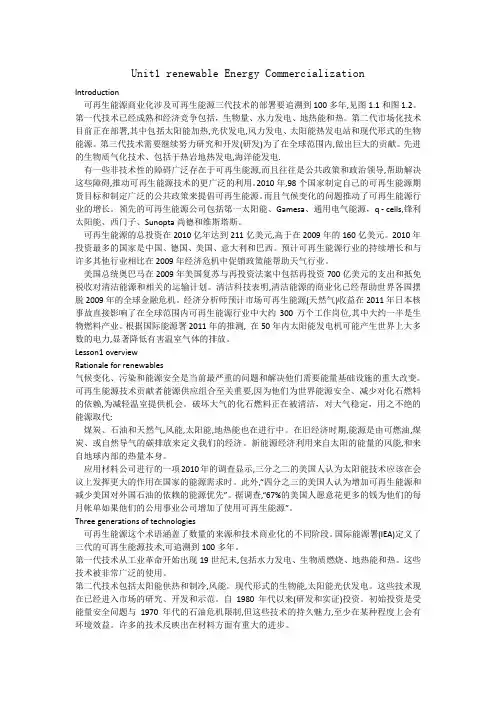
Unit1 renewable Energy CommercializationIntroduction可再生能源商业化涉及可再生能源三代技术的部署要追溯到100多年,见图1.1和图1.2。
第一代技术已经成熟和经济竞争包括,生物量、水力发电、地热能和热。
第二代市场化技术目前正在部署,其中包括太阳能加热,光伏发电,风力发电、太阳能热发电站和现代形式的生物能源。
第三代技术需要继续努力研究和开发(研发)为了在全球范围内,做出巨大的贡献。
先进的生物质气化技术、包括干热岩地热发电,海洋能发电.有一些非技术性的障碍广泛存在于可再生能源,而且往往是公共政策和政治领导,帮助解决这些障碍,推动可再生能源技术的更广泛的利用。
2010年,98个国家制定自己的可再生能源期货目标和制定广泛的公共政策来提倡可再生能源。
而且气候变化的问题推动了可再生能源行业的增长。
领先的可再生能源公司包括第一太阳能、Gamesa、通用电气能源,q - cells,锋利太阳能、西门子、Sunopta尚德和维斯塔斯。
可再生能源的总投资在2010亿年达到211亿美元,高于在2009年的160亿美元。
2010年投资最多的国家是中国、德国、美国、意大利和巴西。
预计可再生能源行业的持续增长和与许多其他行业相比在2009年经济危机中促销政策能帮助天气行业。
美国总统奥巴马在2009年美国复苏与再投资法案中包括再投资700亿美元的支出和抵免税收对清洁能源和相关的运输计划。
清洁科技表明,清洁能源的商业化已经帮助世界各国摆脱2009年的全球金融危机。
经济分析师预计市场可再生能源(天然气)收益在2011年日本核事故直接影响了在全球范围内可再生能源行业中大约300万个工作岗位,其中大约一半是生物燃料产业。
根据国际能源署2011年的推测, 在50年内太阳能发电机可能产生世界上大多数的电力,显著降低有害温室气体的排放。
Lesson1 overviewRationale for renewables气候变化、污染和能源安全是当前最严重的问题和解决他们需要能量基础设施的重大改变。
文献信息:文献标题:A New Controller Scheme for Photovoltaics Power Generation Systems(光伏发电系统的一种新的控制方案)国外作者:Tamer T.N.Khatib,Azah Mohamed,Nowshad Amin文献出处:《European Journal of Scientific Research》,2009,Vol.33 No.3, pp515-524字数统计:英文1337单词,7006字符;中文2149汉字外文文献:A New Controller Scheme for Photovoltaics PowerGeneration SystemsAbstract:This paper presents a new controller scheme for photovoltaic (PV) power generation systems. The proposed PV controller scheme controls both the boost converter and the battery charger by using a microcontroller in order to extract maximum power from the PV array and control the charging process of the battery. The objective of the paper is to present a cost effective boost converter design and an improved maximum power point tracking algorithm for the PV system. A MATLAB based simulation model of the proposed standalone PV system has been developed to evaluate the feasibility of the system in ensuring maximum power point operation.1.IntroductionRecently, the installation of PV generation systems is rapidly growing due to concerns related to environment, global warming, energy security, technology improvements and decreasing costs. PV generation system is considered as a clean and environmentally-friendly source of energy. The main applications of PV systems are in either standalone or grid connected configurations. Standalone PV generationsystems are attractive as indispensable electricity source for remote areas. However, PV generation systems have two major problems which are related to low conversion efficiency of about 9 to 12 % especially in low irradiation conditions and the amount of electric power generated by PV arrays varies continuously with weather conditions. Therefore, many research works are done to increase the efficiency of the energy produced from the PV arrays.The solar cell V-I characteristics is nonlinear and varies with irradiation and temperature. But there is a unique point on the V-I and P-V curves, called as the maximum power point (MPP), at which at this point the PV system is said to operate with maximum efficiency and produces its maximum power output. The location of the MPP is not known but can be traced by either through calculation models or search algorithms. Thus, maximum power point tracking (MPPT) techniques are needed to maintain the PV array’s operating point at its MPP. Many MPPT techniques have been proposed in the literature in which the techniques vary in many aspects, including simplicity, convergence speed, hardware implementation and range of effectiveness. However, the most widely used MPPT technique is the perturbation and observation (P&O) method. This paper presents a simple MPPT algorithm which can be easily implemented and adopted for low cost PV applications. The objective of this paper is to design a novel PV controller scheme with improved MPPT method.The proposed standalone PV controller implementation takes into account mathematical model of each component as well as actual component specification. The dc–dc or boost converter is the front-end component connected between the PV array and the load. The conventional boost converter may cause serious reverse recovery problem and increase the rating of all devices. As a result, the conversion efficiency is degraded and the electromagnetic interference problem becomes severe under this situation. To increase the conversion efficiency, many modified step-up converter topologies have been investigated by several researchers. V oltage clamped techniques have been incorporated in the converter design to overcome the severe reverse-recovery problem of the output diodes. In this paper, focus is also given in the boost converter design. Another important component in the standalone PV systemsis the charge controller which is used to save the battery from possible damage due to over-charging and over-discharging. Studies showed that the life time of a battery can be degraded without using a charge controller.The proposed new controller scheme for the standalone PV system controls both the boost converter and the charge controller in two control steps. The first step is to control the boost converter so as to extract the maximum power point of the PV modules. Here, a high step-up converter is considered for the purpose of stepping up the PV voltage and consequently reducing the number of series-connected PV modules and to maintain a constant dc bus voltage. A microcontroller is used for data acquisition that gets PV module operating current and voltage and is also used to program the MPPT algorithm. The controller adopts the pulse width modulation (PWM) technique to increase the duty cycle of the generated pulses as the PV voltage decreases so as to obtain a stable output voltage and current close to the maximum power point. The second control step is to control the charge controller for the purpose of protecting the batteries. By controlling the charging current using the PWM technique and controlling the battery voltage during charging, voltages higher than the gassing voltage can be avoided.2.Design of the Proposed Photovoltaic SystemMost of the standalone PV systems operate in one mode only such that the PV system charges the battery which in turns supply power to the load. In this mode of operation, the life cycle time of the battery may be reduced due to continuous charging and discharging of the battery. The proposed standalone PV system as shown in terms of a block diagram in Figure 1 is designed to operate in two modes: PV system supplies power directly to loads and when the radiation goes down and the produced energy is not enough, the PV system will charge the battery which in turns supply power to the load. To manage these modes of operation, a controller is connected to the boost converter by observing the PV output power.3.MethodologyFor the purpose of estimating the mathematical models developed for the proposed standalone PV system, simulations were carried in terms of the MATLAB codes. Each PV module considered in the simulation has a rating of 80 Watt at 1000 W/m2, 21.2 V open circuit voltage, 5A short circuit current. The PV module is connected to a block of batteries with of sizing 60 Ah, 48 V.4.Results and DiscussionThe simulation results of the standalone PV system using a simple MPPT algorithm and an improved boost converter design are described in this section. Simulations were carried out for the PV system operating above 30o C ambient temperature and under different values of irradiation. Figure 9 shows the PV array I-V characteristic curve at various irradiation values. From the figure, it is observed that the PV current increase linearly as the irradiation value is increased. However, the PV voltage increases in logarithmic pattern as the irradiation increases. Figure 10 shows the PV array I-V characteristic curve at various temperature values. It is noted from the figure that, the PV voltage decreases as the ambient temperature is increased.Figure 4 compares the PV array P-V characteristics obtained from using the proposed MPPT algorithm and the classical MPPT P&O algorithm. From this figure, it can be seen that by using the proposed MPPT algorithm, the operating point of PV array is much closer to the MPP compared to the using the classical P&O algorithm.In addition, the proposed boost converter is able to give a stable output voltage as shown in Figure 5. In terms of PV array current, it can be seen from Figure 6 that the PV current is closer to the MPP current when using the improved MPPT algorithm. Thus, the track operating point is improved by using the proposed MPPT algorithm. In terms of efficiency of the standalone PV system which is calculated by dividing the load power with the maximum power of PV array, it is noted that the efficiency of the system is better with the proposed MPPT algorithm as compared to using the classical P&O algorithm as shown in Figure 7.5.ConclusionThis paper has presented an efficient standalone PV controller by incorporating an improved boost converter design and a new controller scheme which incorporates both a simple MPPT algorithm and a battery charging algorithm. The simulation results show that the PV controller using the simple MPPT algorithm has provided more power and better efficiency (91%) than the classical P&O algorithm. In addition, the proposed boost converter design gives a better converter efficiency of about 93%. Such a PV controller design can provide efficient and stable power supply for remote mobile applications.中文译文:光伏发电系统的一种新的控制方案摘要:本文提出了一种新的光伏(PV)发电系统控制器方案。
光伏行业常用英文单词在光伏行业中,英语单词是必备的工具,具备一定的英文词汇能力对于从事光伏行业的人士来说至关重要。
本文将介绍光伏行业中常用的英文单词以及它们的中文意义,希望能帮助读者更好地理解和运用这些术语。
1. Solar energy - 太阳能Solar energy refers to the energy derived from the sun's radiation. It is the primary source of power in the solar industry, driving the generation of electricity through solar panels.2. Photovoltaic (PV) - 光伏的Photovoltaic, often abbreviated as PV, is the technology used to convert sunlight directly into electricity. It involves the use of solar cells or modules to capture and convert solar energy.3. Solar panel - 太阳能电池板A solar panel is a device that consists of multiple solar cells connected together. It converts sunlight into electricity through the photovoltaic effect.4. Solar cell - 太阳能电池A solar cell, also known as a photovoltaic cell, is the basic building block of a solar panel. It converts sunlight into electricity by absorbing photons and releasing electrons.5. Solar module - 太阳能模块A solar module, also referred to as a solar panel module, is a packaged assembly of interconnected solar cells. It provides a larger surface area for capturing sunlight and generating electricity.6. Solar farm - 太阳能发电场A solar farm is a large-scale installation of solar panels or modules. It is designed to generate significant amounts of electricity for commercial or utility-scale applications.7. Inverter - 逆变器An inverter is a device used in photovoltaic systems to convert the direct current (DC) produced by solar panels into alternating current (AC) for use in electrical grids or appliances.8. Net metering - 净计量Net metering is a billing arrangement that allows solar energy system owners to receive credit for the excess electricity they generate and feed back into the grid. It promotes the integration of solar power into existing electrical grids.9. Feed-in tariff - 上网电价A feed-in tariff is a policy mechanism that promotes renewable energy generation by providing financial incentives for the production of electricity from renewable sources, such as solar power.10. Solar irradiance - 太阳辐照度Solar irradiance refers to the power per unit area received from the sun in the form of electromagnetic radiation. It is a key parameter in evaluating the potential energy output of solar panels.11. Off-grid - 脱网Off-grid refers to systems or applications that are not connected to the main electrical grid. Off-grid solar systems often rely on batteries to store excess energy for use during periods of low or no sunlight.12. Grid-connected - 并网Grid-connected systems are connected to the main electrical grid and feed excess electricity back into the grid. They allow for both the consumption of solar-generated power and the use of grid power when necessary.13. Photovoltaic efficiency - 光伏效率Photovoltaic efficiency measures how effectively a solar cell or module converts sunlight into electricity. Higher efficiency means a greater conversion rate and more power output.14. Solar thermal - 太阳能热利用Solar thermal refers to the use of solar energy to generate heat. It often involves the use of solar collectors to absorb sunlight and transfer the heat to a fluid, which can then be used for heating or generating electricity.15. Renewable energy - 可再生能源Renewable energy refers to energy sources that can be replenished naturally or essentially indefinitely. Solar energy is considered a renewable energy source, as it relies on the continuous availability of sunlight.以上是光伏行业中常见的英文单词及其中文意义。
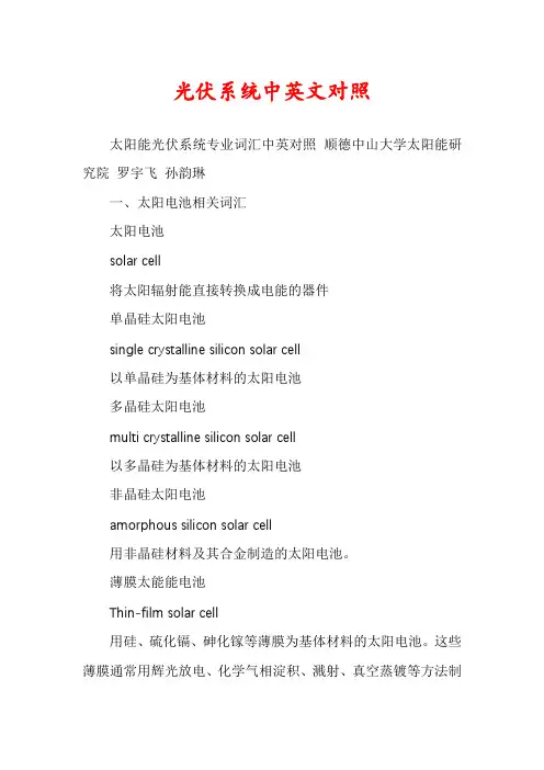
光伏系统中英文对照太阳能光伏系统专业词汇中英对照顺德中山大学太阳能研究院罗宇飞孙韵琳一、太阳电池相关词汇太阳电池solar cell将太阳辐射能直接转换成电能的器件单晶硅太阳电池single crystalline silicon solar cell以单晶硅为基体材料的太阳电池多晶硅太阳电池multi crystalline silicon solar cell以多晶硅为基体材料的太阳电池非晶硅太阳电池amorphous silicon solar cell用非晶硅材料及其合金制造的太阳电池。
薄膜太能能电池Thin-film solar cell用硅、硫化镉、砷化镓等薄膜为基体材料的太阳电池。
这些薄膜通常用辉光放电、化学气相淀积、溅射、真空蒸镀等方法制得。
多结太阳电池multijunction solar cell由多个p\n 结形成的太阳电池。
化合物半导体太阳电池compound semiconductor solar cell 用化合物半导体材料制成的太阳电池带硅太阳电池silicon ribbon solar cell用带状硅制造的太阳电池光电子photo-electron由光电效应产生的电子。
太阳电池的伏安特性曲线I-V characteristic curve of solar cell受光照的太阳电池,在一定的辐照度和温度以及不同的外电路负载下,流入的电流I 和电池端电压V 的关系曲线。
短路电流short-circuit current (Isc)在一定的温度和辐照度条件下,光伏发电器在端电压为零时的输出电流。
开路电压open-circuit voltage (Voc)在一定的温度和辐照度条件下,光伏发电器在空载(开路)情况下的端电压。
最大功率maximum power (Pm)在太阳电池的伏安特性曲线上,电流电压乘积的最大值。
最大功率点maximum power point在太阳电池的伏安特性曲线上对应最大功率的点,亦称最佳工作点。
(文档含英文原文和中文翻译)中英文翻译英文原文Historical Review of Solar EnergySolar generally refers to the suns radiation energy. Carried out in the solar interior from H together into a helium the nuclear reaction, kept a huge release of energy, and continue to the space radiation energy, which is solar energy. This solar nuclear fusion reaction inside the can to maintain the hundreds of millions of first time. Solar radiation to space launch 3.8x10 ^ 23kW power of the radiation, of which 20 billionth of the Earths atmosphere to reach. Solar energy reaching the Earths atmosphere, 30% of the atmosphere reflectance, 23% of atmospheric absorption, and the rest to reach the Earths surface.Its power of 80 trillion kW, that is to say a second exposure to the suns energy on Earth is equivalent to five million tons of coal combustion heat release. The average per square meter in the atmosphere outside the area of energy per minute to receiveabout 1367w. A broad sense of the solar energy on earth many sources, such as w ind energy, chemical energy, potential energy of water and so on. The narrow sense is limited to solar radiation of solar light thermal, photovoltaic and photochemical conversion of the directly.At this stage, the worlds solar energy is still the focus of the study of solar energy power plant, but the diversification of the use of the condenser, and the introduction of flat-plate collector and a low boiling point working fluid, the device gradually expanded up to maximum output power 73.64kW, Objective To compare the clear and practical, cost remains high. The construction of a typical device are as follows: 1901, California built a solar-powered pumping devices, the use of truncated cone condenser power: 7.36kW; 1902 ~ 1908 years, built in the United States five sets of double-cycle solar-powered engines, the use of flat-panel collector and a low boiling point working fluid; in 1913,Human use of solar energy has a long history. China more than 2000 years ago, back in the Warring States period, one will find that the use of four steel mirror to focus sunlight ignition; use of solar energy to dry agricultural products. The development of modern, solar energy has become increasingly widespread use, it includes the use of solar energy solar thermal, solar photovoltaic and solar energy use, such as the photochemical use. The use of solar photochemical reaction, a passive use (photo-thermal conversion) and the photoelectric conversion in two ways. A new solar power and renewable sources of energy use.Silicon photovoltaic cells mainly in the absorption of solar light energy emitted by silicon photocell is mainly extracted from the sand by the development of Bell Labs. Solar energy is the internal or the surface of the sun sunspot continuous process of nuclear fusion reactions produce energy. Earths orbit on the average solar radiation intensity for the 1367w / ㎡. Circumference of the Earths equator to 40000km, and thus calculated the Earths energy can be obtained 173000TW. At sea level standard for peak intensity 1kw/m2, a point on the Earths surface 24h of the annual average radiation intensity 0.20kw / ㎡, which is equivalent to have 102000TW energy Human dependence on these energy to survive, including all other forms of renewable energy (except for geothermal energy resources), although the total amount of solar energy resources is the human equivalent of the energy used by ten thousand times, but low energy density of solar energy, and it vary from place to place, from time to time change, the development and utilization of solar energy which is facing a major problem. These features will make solar energy in the integrated energy systemof the role of subject to certain restrictions.The use of solar cells, through the photoelectric conversion to solar energy conversion is included in electricity, the use of solar water heaters, the use of solar heat hot water and use water for power generation, using solar energy for desalination. Now, the use of solar energy is not very popular, the use of solar power costs are h igh there, the problem of low conversion efficiency, but for satellite solar cells to provide energy has been applied.Although the Earths atmosphere solar radiation to the total energy only 22 billionths of a radiation energy, it has been as high as 173,000 TW, that is to say a second exposure to the suns energy on Earth is equivalent to five million tons of coal. Earth wind energy, hydropower, ocean thermal energy, wave energy and tidal energy as well as some comes from the sun; even in the face of the earths fossil fuels (such as coal, oil, natural gas, etc.) that is fundamentally Since ancient times the storage of solar energy down, so by including a broad range of solar energy is very large, he narrow sense is limited to solar radiation of solar light thermal, photovoltaic and photochemical conversion of the directly.Solar energy is the first time, but also renewable energy. It is rich in resources, can use free of charge, and without transportation, without any pollution to the environment. For mankind to create a new life, so that social and human energy into a era of reducing pollution.Solar cells have to respond to a light and convert solar energy to power the device. Photovoltaic effect can produce many kinds of materials, such as: single crystal silicon, polycrystalline silicon, amorphous silicon, gallium arsenide, copper indium selenium. They are basically the same principle of power generation is now crystal as an example to describe the process of light generation. P-type crystalline silicon available after phosphorus-doped N-type silicon, the formation of P-N junction.When the surface of solar light, the silicon material to be part of photon absorption; photon energy transfer to the silicon atom, electronic transitions have taken place, as a free-electron concentration in the PN junction formed on both sides of the potential difference, when the external circuit connected when the effects of the voltage, there will be a current flowing through the external circuit have a certain amount of output power. The substance of this process are: photon energy into electrical energy conversion process.Si is our planets abundance of storage materials. Since the 19th century,scientists discovered the properties of crystalline silicon semiconductor, it almo st changed everything, even human thought, end of the 20th century. Our lives can be seen everywhere, silicon figure and role of crystalline silicon solar cells is the formation of the past 15 years the fastest growing industry. Production process can be divided into five steps: a, purification process b, the process of pulling rod c, slicing the process of d, the process of system battery e, the course package.Solar photovoltaicIs a component of photovoltaic panels in the sun exposure will generate direct current power generation devices, from virtually all semiconductor materials (eg silicon) are made of thin photovoltaic cells composed of solid. Because there is no part of activity, and would thus be a long time operation would not lead to any loss. Simple photovoltaic cells for watches and computers to provide energy, and more complex PV systems to provide lighting for the housing and power supply. Photovoltaic panels can be made into components of different shapes, and components can be connected to generate more power. In recent years, the surface of the roof and building will be the use of photovoltaic panels components,Even be used as windows, skylights or sheltered part of devices, which are often called photovoltaic facilities with PV systems in buildings.Solar thermalModern technology solar thermal polymerization sunlight and use its energy produced hot water, steam and electricity. In addition to the use of appropriate technology to collect solar energy, the building can also make use of the su ns light and heat energy is added in the design of appropriate equipment, such as large windows or use of the south can absorb and slowly release the sun heat the building materials .According to records, human use of solar energy has more than 3,000 years of history. To solar energy as an energy and power use, only 300 years of history. The real solar as the near future to add much-needed energy, the basis of the future energy mix is the latest thing. Since the 20th century, 70s, solar technology has made rapid advances, solar energy use with each passing day. Solar energy utilization in modern history from the French engineers in 1615 in the Solomon and Germany Cox invented the worlds first solar-powered engines run. The invention is a use of solar energy heating the air to the expansion and pumping machines acting.In 1615 ~ 1900, between the developed world and more than one solar power plant and a number of other solar energy devices. Almost all of these power plantscollect the sun means the use of condenser, engine power is not, the working fluid is water vapor, which is very expensive, not practical value, the majority of individual studies for manufacturing solar enthusiasts. 100 years of the 20th century, the history of the development of solar energy technology in general can be divided into seven stages.1. The First Stage (1900---1920)In this stage, the research focus of solar energy in the world were still on the solar-powered device which variable photospot method were applied and flat plate heat collector and low boiling point actuating medium were started to use; the capacity of the device was gradually expanded with the max. output power of 73.46kW; device was utilized with the definite end-use and in higher cost.The typical built device included: one set of solar energy pumping device constructed in California of U.S in 1901 which employed truncation taper photospot with the power of 7.36kW; 5 sets of twin-circulated solar-powered engine built in U.S in 1902 to 1908 which employed the flat plate heat collector and low boiling point actuating medium; 1 set of solar energy pump comprised of 5 parabolic mirror in a length of 62.5m, width of 4m built in Cairo of Egypt in which the total light collecting area could reach 1250m2.2. The Second Stage (1920-1965)For these 20 years, the research of solar energy was implementing on the poor stage, which the mandate to participate in the development and the research projects had been widely declined due to the mass utilization of fossil fuels and the second world war (1935---1945) while the s olar energy couldn’t satisfy the urgent demand upon the energy. Therefore, the research and development of solar energy was due to be gradually deserted.3. The Third Stage (1945-1965)For these 20 years after the Second World War, some foresight person has noticed that the petroleum and natural gas resources had been rapidly decreased and called for attention on these issues in order to gradually promote the recovery and development of the solar energy research. Solar energy institutes were setup and academic exchanges and exhibitions were held which raised the research upsurge again on solar energy.In this period, great progress was achieved in the research of solar energy, in particular: the foundation theory of selective paints proposed in the First International Solar Thermal Academic Conference in 1955, which black nickel had been developedas the practical selective paints, contributing to development of high-effective heat collector; the practical silicon solar cells developed by Bell Lab in U.S in 1954 which laid the foundation for large scale utilization of photovoltaic generation.Furthermore, there were still other significant results, including:a. One set of 50kW solar stove was built by French National Research Center in 1952;b. The worldwide prototype ammonia-water absorbing air conditioning system heated by flat plate heat collector with the capacity of 5 tons was built in Florida of U.S in 1960;c. An engine equipped with silicon window was invented in 1961.In this stage, research on foundation theory and foundation material of solar energy was reinforced and academic breakthrough, i.e. selective paints and silicon solar cells were achieved. The flat plate had been well developed and ripe in technologies. Progress had been achieved in the research of solar energy absorbing air conditioners and a batch of pilot solar room was established. Preliminary research was conducted on the engine and tower type solar-powered generation technologies.4. The Fourth Stage (1965---1973)In the stage, the research work on solar energy was standstill due to the reason that the utilization technologies of solar energy had entered into the growing stage which was no ripe in process, heavy in investment and lower in effect. Thus it cannot compete with conventional energy, which resulted in the absence of attention and support from the public, enterprise and government.5. The Fifth Stage (1973---1980)After petroleum played a leading role in the worldwide energy structure, it has been a key factor to control the economic and determine the fatal, development and declining of a country. After the explosion of Middle East War at Oc., 1973, OPEC employed the method of declining the production and increasing the price to support the struggle and safeguard the national benefits which resulted in heavy economic attack for those countries that relied on importing large amount of inexpensive petroleum from the region of Middle East. Thus, some people in the western countries were frightened to call that the energy or petroleum crisis had been launched in the world. This crisis made people realized that the existing energy structure should be completely changed and transition to the future energy structure should be speed up.From that on, many countries, especially the industrialized countries turned their attention towards the support on the research and development of solar energy andother renewable energy technologies. The upsurge of developing and utilizing solar energy had been raised again in the world. In 1973, U.S drew up a government scale sunlight power generation program which the research budget for solar energy were increased in a large amount, and solar energy development bank was to established to facilitate the solar energy products to be commercialized. In 1974, Japan published the sunlight program made by the government, among which the solar energy development projects included solar room, industrial-use solar energy system, solar thermal generation, solar cells production system, scattered and large scale photovoltaic generation system. In order to implement this program, the government of Japan input large amount of manpower, material resources and financial resources.The upsurge on the utilization of solar energy raised in 1970s in the world also impacted on China. Some foresight technicians started to devote to the solar energy industry one after another and positively proposed to the relative department of the government and published books and periodicals to introduce the international trends on the utilization of solar energy. Solar stove was popularized and utilized in countryside; solar water heater was launched in the city; solar cells used in space have started to be applied in the ground. In 1975, the first national solar energy utilization working exchanges conference held in An yang, Henan Province further promoted the development of solar energy industry in China. After this meeting, the solar energy research and promotion had been brought into the government program and awarded support of specialized fund and material. In some universities and institutes, solar energy task team and research departments were established one after another. Solar energy research institutes were also launched in some places. At that time, an upsurge on utilization of solar energy was emerging in China.During this period, research and development of solar energy entered into an unprecedented well-developed stage with the following characteristics:a. Each country enhanced planning on solar energy research. Many countries worked out short term and long-term sunlight program. The utilization of solar energy had been a governmental action with intensive support. The international cooperation was very active which some developing countries had started to participate in the utilization of solar energy.b. The research field was expanding; research work was developed day by day and significant results achieved, for example, CPC, vacuum heat collecting pipe, non-crystal silicon solar cells, water-photolyzed hydrogen production and solar energy thermal power generation.c. The solar energy development program worked out by each country existed the problems that the requirement was too high and urgent and insufficient expectation on difficulty in implementation. They have thought to replace the mineral energy in the short time and to utilize the solar energy in large scale. For example, U.S has once scheduled to build a small size solar energy demonstration satellite power station in 1985 and one set of 5 million kW space solar energy power station in 1995. In fact, this program has been adjusted in later, and the space solar energy power station has not yet been realized.d. Products such as solar water heater and solar cells were started to commercialize. The solar energy sector has been preliminarily established with a small scale and ineffective economic effects.6. The Sixth Stage (1980-1992)The upsurge on utilization of solar energy emerged in 1970s was fallen into a stage of being developed in a low and slow step in 1980s. Many countries in the world declined the research budget for solar energy in successive in a large amount, in particular the U.S.The main reasons resulted in this situation were that the international oil price was corrected in a large range while solar energy product cost was still remaining as before which may be of no competitive capability; no any significant breakthrough on solar energy technologies to increase the efficiency and reduce the cost which led to break down people’s confidence to develop solar energy; increased development on nuclear power which may restrain on a certain degree on the development of solar energy.Influenced on the turndown of solar energy in the worldwide in 1980s, research work in China also declined in a certain degree. Due to the reason that the utilization of solar energy was heavy in investment, ineffective in results, difficult in energy storage and large in land covering, solar energy should be considered as the future energy. Some person even proposed that the technology could be introduced after it would be developed successfully. Only few people supported such viewpoint, but it was very harmful which will result in unfavorable influence on the development of solar energy industry.During this period, although the research budget has been mitigated in a large amount, the research work remained uninterruptedly, among which some projects achieved progress which facilitated people to investigate seriously on the program and goads worked out before and to adjust the research focus so that to strive for greatachievement by less input.7. The Seventh Stage (1992---Until Now)Excessive burning of fossil fuel led to worldwide environmental pollution and ecological destruction, which has been threatened the substance and development of human beings. Under such circumstance, UN held the international environment and development conference in Brazil in 1992. On this meeting, a series of importan t document were published including the Environment and Development Manifesto,Agenda of 21st century and UN Framework Pact on Climate Changing in which the environment and development were brought into the integrated framework, and sustainable model was established. After this conference, each country enhanced the development of clean energy technologies, and developed the solar energy in line with the environmental protection so as to make the utilization of solar energy be well developed.After this conference, Chinese government also turned their attention towards the environment and development and pointed out 10 pieces of tactic and measure definitely to develop and popularize the clean energy including solar energy, wind energy, thermal energy, tidal energy and biomass energy in accordance with the reality; worked out Agenda of 21st century in China and further focused the solar energy projects. In 1995, the State Planning, the State Economic and Trade Commission, the State Ministry of Science and Technology worked out the Outline for Development of New and Renewable Energy from 1996 to 2010, which definitely pointed out the goads, objectives and relative tactic and measure towards the development of new and renewable energy from 1996 to 2010 in China. The publishing and implementation of the document further promoted the development of solar energy industry in China.In 1996, UN held the worldwide solar energy summit conference in Zimbabwe. The Solar Energy and Sustainable Development Manifesto was published after the meeting. Important document, i.e.Worldwide Solar Energy 10-Year Action and Program (1996---2005), International Solar Energy Pact, Worldwide Solar Energy Strategic Planning were discussed during the meeting. This meeting further showed eac h country’s commitment to developing the solar energy. Worldwide joint action was required to extensively utilize the solar energy.After 1992, the worldwide utilization of solar energy has entered into a developing stage with the characteristic that:a. The utilization of solar energy can be consistent to the sustainable development and environment protection, and can be carried out jointly to realize thedevelopment strategy in the world;b. Definite development goals with focus projects and effective measure, which will be favorable to overcome the shortage to ensure the long-term development of solar energy industry;c. In the course of expanding the research of solar energy, attention was paid to convert the academic results into production, develop solar energy industry, speed up the progress to be commercialized, expand the utilization field and scale and increase the economic benefits;d. Active international cooperation in the field of solar energy with expanding scale and obvious effect.In view of the review, the development of solar energy in the 20th century was not so smooth. Generally speaking, low tide period was happened after every high tide period. The low tide period lasted for nearly 45 years. The development of solar energy differed with that of coal, petroleum and nuclear energy in understanding and development period, which could be demonstrated that it was very difficulty to develop the solar energy and it cannot be realized to large scale utilize in the short term. On the other hand, it was showed that the utilization of solar energy was also affected by the supply of mineral energy, politics and war. However, in a word, the solar energy has achieved greatly in academic results in 20th century than in any other century.英文翻译太阳能利用史太阳能一般指太阳光的辐射能量。
屋顶光伏电源系统 Roof-mounted PV power system独立家庭电源系统 Off-grid home power system小区太阳能发电系统 Residential area PV power system光伏建筑一体化 BIPV products太阳能发电在宾馆、学校中的应用 Applications of solar PV in hotels and schools 移动信号塔太阳能发电装置 Solar PV power systems for mobile communicationsignal stations移动通信基站-直放站电源 PV power systems for GSM base stations小型并网光伏电站 small on-grid PV power station大型并网光伏电站 large on-grid PV power station乡镇公路太阳能路灯的应用 Solar streetlights for rural roads太阳能建设新农村工程 Solar projects for new villages城市太阳能庭院灯的应用 Solar garden lights for cities乡镇太阳能庭院灯的应用 Solar garden lights for towns郊区太阳能草坪灯工程 Solar lawn lights for suburbs太阳能交通信号灯工程 Installation of solar traffic signs城乡风光互补路灯实例 Wind and PV hybrid streetlights小区风光互补系统 Wind and PV hybrid power systems for residential areas风力发电系统的应用 Wind generating systems太阳能术语知多少光伏矩阵或发电板阵 (Array - photovoltaic)太阳能发电板串联或并联连接在一起形成矩阵.阻流二极管 (Blocking Diode)用来防止反向电流, 在发电板阵中, 阻流二极管用来防止电流流向一个或数个失效或有遮影的发电板 (或一连串的太阳能发电板) 上. 在夜间或低电流出的期间, 防止电流从蓄电池流向光伏发电板矩阵."光伏发电系统平衡 (BOS or Balance of System - photovoltaic)光伏发电系统除发电板矩阵以外的部分. 例如开关, 控制仪表, 电力温控设备, 矩阵的支撑结构, 储电组件等等.旁路二极管 (Bypass Diode)是与光伏发电板并联的二极管. 用来在光电板被遮影或出故障时提供另外的电流通路.光伏发电板 (电池) (Cell-photovoltaic)太阳能发电板中最小的组件.充电显示器 (表) (Charge Monitor/Meter)用以测量电流安培量的装置, 安培表.充电调节器 (Charge Regulator)"用来控制蓄电池充电速度和/或充电状态的装置, 连接于光伏发电板矩阵和蓄电池组之间. 它的主要作用是防止蓄电池被光伏发电板过度充电, 同时监控光伏发电矩阵和/或蓄电池的电压."组件 (Components)指用于建立太阳能电源系统所需的其他装置.交直流转换器 (Converter)将交流电转换成直流电的装置.晶体状 (Crystalline)具有三维的重复的原子结构.直流电 (DC)"两种电流的形态之一, 常见于使用电池的物件中, 如收音机, 汽车, 手提电脑, 手机等等."无序结构 (Disordered)减小并消除晶格的局限性. 提供新的自由度, 从而可在多维空间中放置其他元素. 使它们以前所未有的方式互相作用. 这种技术应用多种元素以及复合材料. 它们在位置, 移动及成分上的不规则可消除结构的局限性, 因而产生新的局部规则环境. 而这些新的局部环境决定了这些材料的物理性质, 电子性质以及化学性质. 因此使得合成具有新颍机理的新型材料成为可能.电网连接 - 光伏发电 (Grid-Connected - photovoltaic)是一种由光伏发电板阵向电网提供电力的光伏发电系统. 这些系统可由供电公司或个别楼宇来运作.直流交流转换器 (Inverter)用来将直流电转换成交流电的装置.千瓦 (Kilowatt)1000瓦特, 一个灯泡通常使用40至100瓦特的电力.百万瓦特 (Megawatt)1,000,000瓦特光伏发电板 (Module - photovoltaic)光伏电池以串联方式连在一起组成发电板.奥佛电子 (Ovonic)[以S. R. 奥佛辛斯基(联合太阳能公司创始人)及电子的组合命名] - 用来描述我们独有的材料, 产品和技术的术语.奥佛辛斯基效应 (Ovshinsky effect)一种特别的玻璃状薄膜在极小电压的作用下从一种非导体转变成一种半导体的效应..并联连接 (Parallel Connection)一种发电板连接方法. 这种连接法使电压保持相同, 但电流成倍数增加峰值输出功能 (Peak Power)持续一段时间(通常是10到30秒)的最大能量输出.光伏 (Photovoltaic - PV)光能到电能的直接转换.光伏发电板 (电池) (Photovoltaic Cell)经过特殊处理可将太阳能辐射转换成电力的半导体材料.卷到卷工序 (Roll-to-Roll Process)将整卷的基件连续地转变成整卷的产品的工序.串联连接 (Series Connection)电流不变电压倍增的连接方式.太阳能 (Solar)来自太阳的能量.太阳能收集器 (Solar Collectors)用以捕获来自太阳的光能或热能的装置. 太阳收集器用于太阳能热水器系统中 (常见于住家), 而光伏能收集器则是用于太阳能电力系统.太阳能加热 (Solar Heating)利用来自太阳的热能发电的技术或系统. 太阳能收集器用于太阳能热水器系统中(常见于住家), 而光伏能收集器则是用于太阳能电力系统中太阳能发电模块或太阳能发电板 (Solar Module or Solar Panel)一些由太阳能发电板单元所组成的太阳能发电板板块.稳定能量转换效率 (Stabilized Energy Conversion Efficiency)长期的电力输出与光能输入比例.系统, 平衡系统 (Systems; Balance of Systems)"太阳能电力系统包括了光伏发电板矩阵和其它的部件. 这些部件可使这些太阳能发电板得以应用在需要可控直流电或交流电的住家和商业设施中. 用于太阳能电力系统的其它部件包括:接线和短路装置, 充电调压器,逆变器, 仪表和接地部件."薄膜 (Thin-Film)在基片上形成的很薄的材料层.伏特 (Volts)电动势能单位. 能促使一安培的电流通过一欧姆的电阻.电压 (Voltage)电势的量.电压表 (Voltage Meter)用以测量电压的装置.瓦特 (Watts)用电压乘以电流的值来衡量的电力度.。
Ultra-High Efficiency Photovoltaic Cells for Large Scale Solar Power GenerationYoshiaki NakanoAbstract The primary targets of our project are to dras-tically improve the photovoltaic conversion efficiency and to develop new energy storage and delivery technologies. Our approach to obtain an efficiency over40%starts from the improvement of III–V multi-junction solar cells by introducing a novel material for each cell realizing an ideal combination of bandgaps and lattice-matching.Further improvement incorporates quantum structures such as stacked quantum wells and quantum dots,which allow higher degree of freedom in the design of the bandgap and the lattice strain.Highly controlled arrangement of either quantum dots or quantum wells permits the coupling of the wavefunctions,and thus forms intermediate bands in the bandgap of a host material,which allows multiple photon absorption theoretically leading to a conversion efficiency exceeding50%.In addition to such improvements, microfabrication technology for the integrated high-effi-ciency cells and the development of novel material systems that realizes high efficiency and low cost at the same time are investigated.Keywords Multi-junctionÁQuantum wellÁConcentratorÁPhotovoltaicINTRODUCTIONLarge-scale photovoltaic(PV)power generation systems, that achieve an ultra-high efficiency of40%or higher under high concentration,are in the spotlight as a new technology to ease drastically the energy problems.Mul-tiple junction(or tandem)solar cells that use epitaxial crystals of III–V compound semiconductors take on the active role for photoelectric energy conversion in such PV power generation systems.Because these solar cells operate under a sunlight concentration of5009to10009, the cost of cells that use the epitaxial crystal does not pose much of a problem.In concentrator PV,the increased cost for a cell is compensated by less costly focusing optics. The photons shining down on earth from the sun have a wide range of energy distribution,from the visible region to the infrared region,as shown in Fig.1.Multi-junction solar cells,which are laminated with multilayers of p–n junctions configured by using materials with different band gaps,show promise in absorbing as much of these photons as possible,and converting the photon energy into elec-tricity with minimum loss to obtain high voltage.Among the various types of multi-junction solar cells,indium gallium phosphide(InGaP)/gallium arsenide(GaAs)/ger-manium(Ge)triple-junction cells that make full use of the relationship between band gaps and diverse lattice con-stants offered by compound semiconductors have the advantage of high conversion efficiency because of their high-quality single crystal with a uniform-size crystal lat-tice.So far,a conversion efficiency exceeding41%under conditions where sunlight is concentrated to an intensity of approximately5009has been reported.The tunnel junction with a function equivalent to elec-trodes is inserted between different materials.The positive holes accumulated in the p layer and the electrons in the adjacent n layer will be recombined and eliminated in the tunnel junction.Therefore,three p–n junctions consisting of InGaP,GaAs,and Ge will become connected in series. The upper limit of the electric current is set by the mini-mum value of photonflux absorbed by a single cell.On the other hand,the sum of voltages of three cells make up the voltage.As shown in Fig.1,photons that can be captured in the GaAs middle cell have a smallflux because of the band gap of each material.As a result,the electric currentoutputAMBIO2012,41(Supplement2):125–131 DOI10.1007/s13280-012-0267-4from the GaAs cell theoretically becomes smaller than that of the others and determines the electric current output of the entire tandem cell.To develop a higher efficiency tandem cell,it is necessary to use a material with a band gap narrower than that of GaAs for the middle cell.In order to obtain maximum conversion efficiency for triple-junction solar cells,it is essential to narrow down the middle cell band gap to 1.2eV and increase the short-circuit current density by 2mA/cm 2compared with that of the GaAs middle cell.When the material is replaced with a narrower band gap,the output voltage will drop.However,the effect of improving the electric current balance out-performs this drop in output voltage and boosts the effi-ciency of the entire multi-junction cell.When a crystal with such a narrow band gap is grown on a Ge base material,lattice relaxation will occur in the middle of epitaxial crystal growth because the lattice constants of narrower band-gap materials are larger than that of Ge (as shown in Fig.2).As a result,the carrier transport properties will degrade due to dislocation.Researchers from the international research center Solar Quest,the University of Tokyo,aim to move beyond such material-related restrictions,and obtain materials and structures that have effective narrow band gaps while maintaining lattice matching with Ge or GaAs.To achieve this goal,we have taken three approaches as indicated in Fig.3.These approaches are explained in detail below.DILUTE NITROGEN-ADDED BULK CRYSTAL Indium gallium nitride arsenide (InGaNAs)is a bulk material consists of InGaAs,which contains several percent of nitrogen.InGaNAs has a high potential for achieving a narrow band gap while maintaining lattice matching with Ge or GaAs.However,InGaNAs has a fatal problem,that is,a drop in carrier mobility due to inhomogeneousdistribution of nitrogen (N).To achieve homogeneous solid solution of N in crystal,we have applied atomic hydrogen irradiation in the film formation process and addition of a very small amount of antimony (Sb)(Fig.3).The atomic hydrogen irradiation technology and the nitrogen radical irradiation technology for incorporating N efficiently into the crystal can be achieved only through molecular beam epitaxy (MBE),which is used to fabricate films under high vacuum conditions.(Nitrogen radical irradiation is a technology that irradiates the surface of a growing crystal with nitrogen atoms that are resolved by passing nitrogen through a plasma device attached to the MBE system.)Therefore,high-quality InGaNAs has been obtained only by MBE until now.Furthermore,as a small amount of Sb is also incorporated in a crystal,it is nec-essary to control the composition of five elements in the crystal with a high degree of accuracy to achieve lattice matching with Ge or GaAs.We have overcome this difficulty by optimizing the crystal growth conditions with high precision and devel-oped a cell that has an InGaNAs absorption layer formed on a GaAs substrate.The short-circuit current has increased by 9.6mA/cm 2for this cell,compared with a GaAs single-junction cell,by narrowing the band gap down to 1.0eV.This technology can be implemented not only for triple-junction cells,but also for higher efficiency lattice-matched quadruple-junction cells on a Ge substrate.In order to avoid the difficulty of adjusting the compo-sition of five elements in a crystal,we are also taking an approach of using GaNAs with a lattice smaller than that of Ge or GaAs for the absorption layer and inserting InAs with a large lattice in dot form to compensate for the crystal’s tensile strain.To make a solid solution of N uniformly in GaNAs,we use the MBE method for crystal growth and the atomic hydrogen irradiation as in the case of InGaNAs.We also believe that using 3D-shaped InAs dots can effectively compensate for the tensile strainthatFig.1Solar spectrum radiated on earth and photon flux collected by the top cell (InGaP),middle cell (GaAs),and bottom cell (Ge)(equivalent to the area of the filled portions in the figure)occurs in GaNAs.We have measured the characteristics of a single-junction cell formed on a GaAs substrate by using a GaNAs absorption layer with InAs dots inserted.Figure 4shows that we were able to succeed in enhancing the external quantum efficiency in the long-wavelength region (corresponding to the GaNAs absorp-tion)to a level equal to GaAs.This was done by extending the absorption edge to a longer wavelength of 1200nm,and increasing the thickness of the GaNAs layer by increasing the number of laminated InAs quantum dot layers.This high quantum efficiency clearly indicates that GaNAs with InAs dots inserted has the satisfactory quality for middle cell material (Oshima et al.2010).STRAIN-COMPENSATED QUANTUM WELL STRUCTUREIt is extremely difficult to develop a narrow band-gap material that can maintain lattice matching with Ge orGaAs unless dilute nitrogen-based materials mentioned earlier are used.As shown in Fig.2,the conventionally used material InGaAs has a narrower band gap and a larger lattice constant than GaAs.Therefore,it is difficult to grow InGaAs with a thickness larger than the critical film thickness on GaAs without causing lattice relaxation.However,the total film thickness of InGaAs can be increased as an InGaAs/GaAsP strain-compensated multi-layer structure by laminating InGaAs with a thickness less than the critical film thickness in combination with GaAsP that is based on GaAs as well,but has a small lattice constant,and bringing the average strain close to zero (Fig.3.).This InGaAs/GaAsP strain-compensated multilayer structure will form a quantum well-type potential as shown in Fig.5.The narrow band-gap InGaAs layer absorbs the long-wavelength photons to generate electron–hole pairs.When these electron–hole pairs go over the potential bar-rier of the GaAsP layer due to thermal excitation,the electrons and holes are separated by a built-in electricfieldFig.2Relationship between band gaps and lattice constants of III–V-based and IV-based crystalsto generate photocurrent.There is a high probability of recombination of electron–hole pairs that remain in the well.To avoid this recombination,it is necessary to take out the electron–hole pairs efficiently from the well and transfer them to n-type and p-type regions without allowing them to be recaptured into the well.Designing thequantumFig.3Materials and structures of narrow band-gap middle cells being researched by thisteamFig.4Spectral quantum efficiency of GaAs single-junction cell using GaNAs bulk crystal layer (inserted with InAs dots)as the absorption layer:Since the InAs dot layer and the GaNAs bulk layer are stacked alternately,the total thickness of GaNAs layers increases as the number of stacked InAs dot layers is increased.The solid line in the graph indicates the data of a reference cell that uses GaAs for its absorption layer (Oshima et al.2010)well structure suited for this purpose is essential for improving conversion efficiency.The high-quality crystal growth by means of the metal-organic vapor phase epitaxy (MOVPE)method with excellent ability for mass production has already been applied for InGaAs and GaAsP layers in semiconductor optical device applications.Therefore,it is technologically quite possible to incorporate the InGaAs/GaAsP quantum well structure into multi-junction solar cells that are man-ufactured at present,only if highly accurate strain com-pensation can be achieved.As the most basic approach related to quantum well structure design,we are working on fabrication of super-lattice cells with the aim of achieving higher efficiency by making the GaAsP barrier layer as thin as possible,and enabling carriers to move among wells by means of the tunnel effect.Figure 6shows the spectral quantum effi-ciency of a superlattice cell.In this example,the thickness of the GaAsP barrier layer is 5nm,which is not thin enough for proper demonstration of the tunnel effect.When the quantum efficiency in the wavelength range (860–960nm)that corresponds to absorption of the quan-tum well is compared between a cell,which has a con-ventionally used barrier layer and a thickness of 10nm or more,and a superlattice cell,which has the same total layer thickness of InGaAs,the superlattice cell demonstrates double or higher quantum efficiency.This result indicates that carrier mobility across quantum wells is promoted by even the partial use of the tunnel effect.By increasing the P composition in the GaAsP layer,the thickness of well (or the In composition)can be increased,and the barrier layer thickness can be reduced while strain compensation is maintained.A cell with higher quantum efficiency can befabricated while extending the absorption edge to the long-wavelength side (Wang et al.2010,2012).GROWTH TECHNIQUE FOR STRAIN-COMPENSATED QUANTUM WELLTo reduce the strain accumulated in the InGaAs/GaAsP multilayer structure as close to zero as possible,it is nec-essary to control the thickness and atomic content of each layer with high accuracy.The In composition and thickness of the InGaAs layer has a direct effect on the absorption edge wavelength and the GaAsP layer must be thinned to a satisfactory extent to demonstrate fully the tunnel effect of the barrier layer.Therefore,it is desirable that the average strain of the entire structure is adjusted mainly by the P composition of the GaAsP layer.Meanwhile,for MOVPE,there exists a nonlinear rela-tionship between the P composition of the crystal layer and the P ratio [P/(P ?As)]in the vapor phase precursors,which arises from different absorption and desorption phenomena on the surface.As a result,it is not easy to control the P composition of the crystal layer.To break through such a difficulty and promote efficient optimiza-tion of crystal growth conditions,we have applied a mechanism to evaluate the strain of the crystal layer during growth in real time by sequentially measuring the curvature of wafers during growth with an incident laser beam from the observation window of the reactor.As shown in Fig.7,the wafer curvature during the growth of an InGaAs/GaAsP multilayer structure indicates a periodic behavior.Based on a simple mechanical model,it has become clear that the time changes ofwaferFig.5Distribution of potential formed by the InGaAs/GaAsP strain-compensated multilayer structure:the narrow band-gap InGaAs layer is sandwiched between wide band-gap GaAsP layers and,as a result,it as quantum well-type potential distribution.In the well,electron–hole pairs are formed by absorption of long-wavelength photons and at the same time,recombination of electrons and holes takes place.The team from Solar Quest is focusing on developing a superlattice structure with the thinnest GaAsP barrier layercurvature are proportionate to the strain of the crystal layer relative to a substrate during the growing process.One vibration cycle of the curvature is same as the growth time of an InGaAs and GaAsP pair (Sugiyama et al.2011).Therefore,the observed vibration of the wafer curvature reflects the accumulation of the compression strain that occurs during InGaAs growth and the release of the strain that occurs during GaAsP growth.When the strain is completely compensated,the growth of the InGaAs/GaAsP pair will cause this strain to return to the initial value and the wafer curvature will vibrate with the horizontal line as the center.As shown in Fig.7,strain can be compensated almost completely by adjusting the layer structure.Only by conducting a limited number of test runs,the use of such real-time observation technology of the growth layer enables setting the growth conditions for fabricating the layer structure for which strain has been compensated with highaccuracy.Fig.6Spectral quantum efficiency of GaAs single-junction cell using InGaAs/GaAsP superlattice as theabsorption layer:This structure consists of 60layers of InGaAs quantum wells.The graph also shows data of a reference cell that uses GaAs for its absorption layer (Wang et al.2010,2012)Fig.7Changes in wafer curvature over time during growth of the InGaAs/GaAsP multilayer structure.This graph indicates the measurement result and the simulation result of the curvature based on the layer structure(composition ?thickness)obtained by X-ray diffraction.Since compressive strain is applied during InGaAs growth,the curvature decreases as time passes.On the other hand,since tensile strain is applied during GaAsP growth,the curvature changes in the oppositedirection (Sugiyama et al.2011)FUTURE DIRECTIONSIn order to improve the conversion efficiency by enhancing the current matching of multi-junction solar cells using III–V compound semiconductors,there is an urgent need to create semiconductor materials or structures that can maintain lattice matching with Ge or GaAs,and have a band gap of1.2eV.As for InGaNAs,which consists of InGaAs with several percent of nitrogen added,we have the prospect of extending the band edge to1.0eV while retaining sufficient carrier mobility for solar cells by means of atomic hydrogen irradiation and application of a small quantity of Sb during the growth process.In addition,as for GaNAs bulk crystal containing InAs dots,we were able to extend the band edge to1.2eV and produce a high-quality crystal with enoughfilm thickness to achieve the quantum efficiency equivalent to that of GaAs.These crystals are grown by means of MBE. Therefore,measures that can be used to apply these crys-tals for mass production,such as migration to MOVPE, will be investigated after demonstrating their high effi-ciency by embedding these crystals into multi-junction cells.As for the InGaAs/GaAsP strain-compensated quantum well that can be grown using MOVPE,we are working on the development of a thinner barrier layer while compen-sating for the strain with high accuracy by real-time observation of the wafer curvature.We have had the prospect of achieving a quantum efficiency that will sur-pass existing quantum well solar cells by promoting the carrier transfer within the multilayer quantum well struc-ture using the tunnel effect.As this technology can be transferred quite easily to the existing multi-junction solar cell fabrication process,we strongly believe that this technology can significantly contribute to the efficiency improvement of the latest multi-junction solar cells. REFERENCESOshima,R.,A.Takata,Y.Shoji,K.Akahane,and Y.Okada.2010.InAs/GaNAs strain-compensated quantum dots stacked up to50 layers for use in high-efficiency solar cell.Physica E42: 2757–2760.Sugiyama,M.,K.Sugita,Y.Wang,and Y.Nakano.2011.In situ curvature monitoring for metalorganic vapor phase epitaxy of strain-balanced stacks of InGaAs/GaAsP multiple quantum wells.Journal of Crystal Growth315:1–4.Wang,Y.,Y.Wen,K.Watanabe,M.Sugiyama,and Y.Nakano.2010.InGaAs/GaAsP strain-compensated superlattice solar cell for enhanced spectral response.In Proceedings35th IEEE photovoltaic specialists conference,3383–3385.Wang,Y.P.,S.Ma,M.Sugiyama,and Y.Nakano.2012.Management of highly-strained heterointerface in InGaAs/GaAsP strain-balanced superlattice for photovoltaic application.Journal of Crystal Growth.doi:10.1016/j.jcrysgro.2011.12.049. AUTHOR BIOGRAPHYYoshiaki Nakano(&)is Professor and Director General of Research Center for Advanced Science and Technology,the University of Tokyo.His research interests include physics and fabrication tech-nologies of semiconductor distributed feedback lasers,semiconductor optical modulators/switches,monolithically integrated photonic cir-cuits,and high-efficiency heterostructure solar cells.Address:Research Center for Advanced Science and Technology, The University of Tokyo,4-6-1Komaba,Meguro-ku,Tokyo153-8904,Japan.e-mail:nakano@rcast.u-tokyo.ac.jp。
光伏行业英文词汇Cell 电池Crystalline silicon 晶体硅Photovoltaic 光伏bulk properties 体特性at ambient temperature 在室温下wavelength 波长absorption coefficient 吸收系数electron-hole pairs 电子空穴对photon 光子density 密度defect 缺陷surface 表面electrode 电极p-type for hole extraction p型空穴型n-type for electron extraction n 型电子型majority carriers 多数载流子minority carriers 少数载流子surface recombination velocity (SRV)表面复合速率back surface field (BSF)背场at the heavily doped regions 重掺杂区saturation current density Jo 饱和电流密度thickness 厚度contact resistance 接触电阻concentration 浓度boron 硼Gettering techniques吸杂nonhomogeneous 非均匀的solubility 溶解度selective contacts 选择性接触insulator 绝缘体oxygen 氧气hydrogen 氢气Plasma enhanced chemical vapor deposition PECVDInterface 界面The limiting efficiency 极限效率reflection 反射light- trapping 光陷intrinsic material 本征材料bifacial cells 双面电池monocrystalline 单晶float zone material FZ-Si Czochralski silicon Cz-Si industrial cells 工业电池a high concentration of oxygen 高浓度氧Block or ribbon 块或硅带Crystal defects 晶体缺陷grain boundaries 晶界dislocation 位错solar cell fabrication 太阳能电池制造impurity 杂质P gettering effect 磷吸杂效果Spin-on 旋涂supersaturation 过饱和dead layer 死层electrically inactive phosphorus 非电活性磷interstitial 空隙the eutectic temperature 共融温度boron-doped substrate 掺硼基体passivated emitter and rear locally diffused cells PERL电池losses 损失the front surface 前表面metallization techniques 金属化技术metal grids 金属栅线laboratory cells 实验室电池the metal lines 金属线selective emitter 选择性发射极photolithographic 光刻gradient 斜度precipitate 沉淀物localized contacts 局部接触point contacts 点接触passivated emitter rear totally diffused PERTsolder 焊接bare silicon 裸硅片high refraction index 高折射系数reflectance 反射encapsulation 封装antireflection coating ARC减反射层an optically thin dielectric layer 光学薄电介层interference effects 干涉效应texturing 制绒alkaline solutions 碱溶液etch 刻蚀/腐蚀anisotropically 各向异性地plane 晶面pyramids 金字塔a few microns 几微米etching time and temperature 腐蚀时间和温度manufacturing process 制造工艺process flow 工艺流程high yield 高产量starting material 原材料solar grade 太阳级a pseudo-square shape 单晶型状saw damage removal 去除损伤层fracture 裂纹acid solutions 酸溶液immerse 沉浸tank 槽texturization 制绒microscopic pyramids 极小的金字塔size 尺寸大小hinder the formation of the contacts 阻碍电极的形成the concentration,the temperature and the agitation of the solution 溶液的浓度,温度和搅拌the duration of the bath 溶液维持时间alcohol 酒精improve 改进增加homogeneity 同质性wettability 润湿性phosphorus diffusion 磷扩散eliminate adsorbed metallic impurities 消除吸附的金属杂质quartz furnaces 石英炉quartz boats 石英舟quartz tube 石英炉管bubbling nitrogen through liquid POCL3 小氮belt furnaces 链式炉back contact cell 背电极电池reverse voltage 反向电压reverse current 反向电流amorphous glass of phospho-silicates 非晶玻璃diluted HF 稀释HF溶液junction isolation 结绝缘coin-stacked 堆放barrel-type reactors 桶状反应腔fluorine 氟fluorine compound 氟化物simultaneously 同时地high throughput 高产出ARC deposition 减反层沉积Titanium dioxide TiO2Refraction index 折射系数Encapsulated cell 封装电池Atmospheric pressure chemical vapor deposition APCVDSprayed from a nozzle 喷嘴喷雾Hydrolyze 水解Spin -on 旋涂Front contact print 正电极印刷The front metallization 前面金属化Low contact resistance to silicon 低接触电阻Low bulk resistivity 低体电阻率Low line width with high aspect ratio 低线宽高比Good mechanical adhesion 好机械粘贴solderability 可焊性screen printing 丝网印刷comblike pattern 梳妆图案finger 指条bus bars 主栅线viscous 粘的solvent 溶剂back contact print 背电极印刷both silver and aluminum 银铝form ohmic contact 形成欧姆接触warp 弯曲cofiring of metal contacts 电极共烧organic components of the paste 浆料有机成分burn off 烧掉sinter 烧结perforate 穿透testing and sorting 测试分选I-V curve I-V曲线Module 组件Inhomogeneous 不均匀的Gallium 镓Degradation 衰减A small segregation coefficient 小分凝系数Asymmetric 不对称的High resolution 高分辨率Base resistivity 基体电阻率The process flow 工艺流程Antireflection coating 减反射层Cross section of a solar cell 太阳能电池横截面Dissipation 损耗Light-generated current 光生电流Incident photons 入射光子The ideal short circuit flow 理想短路电路The depletion region 耗尽区Quantum efficiency 量子效率Blue response 蓝光效应Spectral response 光谱响应Light-generated carriers 光生载流子Forward bias 正向偏压Simulation 模拟Equilibrium 平衡Superposition 重合The fourth quadrant 第四象限The saturation current 饱和电流Io Fill factor 填充因子FF Graphically 用图象表示The maximum theoretical FF 理论上Empirically 经验主义的Normalized Voc 规范化VocThe ideality factor n-factor 理想因子Terrestrial solar cells 地球上的电池At a temperature of 25C 25度下Under AM1.5 conditions 在AM1.5环境下Efficiency is defined as ××定义为Fraction 分数Parasitic resistances 寄生电阻Series resistance 串联电阻Shunt resistance 并联电阻The circuit diagram 电路图Be sensitive to temperature 易受温度影响The band gap of a semiconductor 半导体能隙The intrinsic carrier concentration 本征载流子的浓度Reduce the optical losses 减少光损Deuterated silicon nitride 含重氢氮化硅Buried contact solar cells BCSC Porous silicon PS 多孔硅Electrochemical etching 电化学腐蚀Screen printed SP 丝网印刷A sheet resistance of 45-50 ohm/sq 45到50方块电阻The reverse saturation current density Job 反向饱和电流密度Destructive interference 相消干涉Surface textingInverted pyramid 倒金字塔Four point probe 四探针Saw damage etchAlkaline 碱的Cut groove 开槽Conduction band 导带Valence band 价带B and O simultaneously in silicon 硼氧共存Iodine/methanol solution 碘酒/甲醇溶液Rheology 流变学Spin-on dopants 旋涂掺杂Spray-on dopants 喷涂掺杂The metallic impurities 金属杂质One slot for two wafers 一个槽两片Throughput 产量A standard POCL3 diffusion 标准POCL3扩散Back-to-back diffusion 背靠背扩散Heterojunction with intrinsic thin -layer HIT电池Refine 提炼Dye sensitized solar cell 染料敏化太阳电池Organic thin film solar cell 有机薄膜电池Infra red 红外光Unltra violet 紫外光Parasitic resistance 寄生电阻Theoretical efficiency 理论效率Busbar 主栅线Kerf loss 锯齿损失Electric charge 电荷Covalent bonds 共价键The coefficient of thermal expansion (CTE) 热膨胀系数Bump 鼓泡Alignment 基准Fiducial mark 基准符号Squeegee 橡胶带Isotropic plasma texturing 各向等离子制绒Block-cast multicrystalline silicon 整铸多晶硅Parasitic junction removal 寄生结的去除Iodine ethanol 碘酒Deionised water 去离子水Viscosity 粘性Mesh screen 网孔Emulsion 乳胶Properties of light 光特性Electromagnetic radiation 电磁辐射The visible light 可见光The wavelength,denoted by R 用R 表示波长An inverse relationship between……and……given by the equation:相反关系,可用方程表示Spectral irradiance 分光照度……is shown in the figure below. Directly convert electricity into sunlight 直接将电转换成光Raise an electron to a higher energy state 电子升入更高能级External circuit 外电路Meta-stable 亚稳态Light-generated current 光生电流Sweep apart by the electric field Quantum efficiency 量子效率The fourth quadrant 第四象限The spectrum of the incident light 入射光谱The AM1.5 spectrumThe FF is defined as the ratio of ……to……Graphically 如图所示Screen-printed solar cells 丝网印刷电池Phosphorous diffusion 磷扩散A simple homongeneous diffusion 均匀扩散Blue response 蓝光相应Shallow emitter 浅结Commercial production 商业生产Surface texturing to reduce reflection 表面制绒Etch pyramids on the wafer surface with a chemical solutionCrystal orientationTitanium dioxide TiO2PasteInorganic 无机的Glass 玻璃料DopantCompositionParticle sizeDistributionEtch SiNxContact pathSintering aidAdhesion 黏合性Ag powderMorphology 形态CrystallinityGlass effect on Ag/Si interface Reference cellOrganicResin 树脂Carrier 载体Rheology 流变性Printability 印刷性Aspect ratio 高宽比Functional groupMolecular weightAdditives 添加剂Surfactant 表面活性剂Thixotropic agent 触变剂Plasticizer 可塑剂Solvent 溶剂Boiling pointVapor pressure蒸汽压Solubility 溶解性Surface tension 表面张力Solderability Viscosity 黏性Solids contentFineness of grind ,研磨细度Dried thicknessFired thicknessDrying profilePeak firing temp300 mesh screenEmulsion thickness 乳胶厚度StorageShelf life 保存期限Thinning 稀释Eliminate Al bead formation 消除铝珠Low bowingWet depositPattern design: 100um*74太阳电池solar cell单晶硅太阳电池single crystalline silicon solar cell多晶硅太阳电池so multi crystalline silicon solar cell非晶硅太阳电池amorphous silicon solar cell薄膜太能能电池Thin-film solar cell多结太阳电池multijunction solar cell 化合物半导体太阳电池compound semiconductor solar cell用化合物半导体材料制成的太阳电池带硅太阳电池silicon ribbon solar cell光电子photo-electron短路电流short-circuit current (Isc)开路电压open-circuit voltage (V oc)最大功率maximum power (Pm)最大功率点maximum power point最佳工作点电压optimum operating voltage (Vn)最佳工作点电流optimum operating current (In)填充因子fill factor(curve factor)曲线修正系数curve correction coefficient太阳电池温度solar cell temperature串联电阻series resistance并联电阻shunt resistance转换效率cell efficiency暗电流dark current暗特性曲线dark characteristic curve光谱响应spectral response(spectral sensitivity)太阳电池组件module(solar cell module)隔离二极管blocking diode旁路二极管bypass (shunt) diode组件的电池额定工作温度NOCT(nominal operating cell temperature)短路电流的温度系数temperature coefficients of Isc开路电压的温度系数temperature coefficients of V oc峰值功率的温度系数temperature coefficients of Pm组件效率Module efficiency峰瓦watts peak额定功率rated power额定电压rated voltage额定电流rated current太阳能光伏系统solar photovoltaic (PV) system并网太阳能光伏发电系统Grid-Connected PV system独立太阳能光伏发电系统Stand alone PV system太阳能控制器solar controller逆变器inverter孤岛效应islanding逆变器变换效率inverter efficiency方阵(太阳电池方阵) array (solar cell array)子方阵sub-array (solar cell sub-array)充电控制器charge controller直流/直流电压变换器DC/DC converter(inverter)直流/交流电压变换器DC/AC converter(inverter)电网grid太阳跟踪控制器sun-tracking ontroller 并网接口utility interface光伏系统有功功率active power of PV power station光伏系统无功功率reactive power of PV power station光伏系统功率因数power factor of PV power station公共连接点point of common coupling 接线盒junction box发电量power generation输出功率output power交流电Alternating current断路器Circuit breaker汇流箱Combiner box配电箱Distribution box电能表Supply meter变压器Transformer太阳能光伏建筑一体化Building-integrated PV (BIPV)辐射radiation太阳辐照度Solar radiation散射辐照(散射太阳辐照)量diffuse irradiation(diffuse insolation)直射辐照direct irradiation (direct insolation)总辐射度(太阳辐照度) global irradiance (solar global irradiance)辐射计radiometer方位角Azimuth angle倾斜角Tilt angle太阳常数solar constant大气质量(AM) air mass太阳高度角solar elevation angle标准太阳电池standard solar cell (reference solar cell)太阳模拟器solar simulator太阳电池的标准测试条件为:环境温度25±2℃,用标准测量的光源辐照度为1000W/m2 并且有标准的太阳光谱辐照度分布。
太阳能电池太阳电池的材料种类非常的多,可以有非晶硅、多晶硅、CdTe、CuIn x Ga(1-x)Se2等半导体的、或三五族、二六族的元素链结的材料,简单地说,凡光照后,而产(Silicon Based)、第二代为薄膜(Thin Film)、第三代新观念研发(New Concept)、第四代复合薄膜材料。
第一代太阳能电池发展最长久技术也最成熟。
可分为,单晶硅(Monocrystalline Silicon)、多晶硅(Polycrystalline Silicon)、非晶硅(Amorphous Silicon)。
以应用来说是以前两者单晶硅与多晶硅为大宗。
第二代薄膜太阳能电池以薄膜制程来制造电池。
种类可分为碲化镉(Cadmium Telluride CdTe)、铜铟硒化物(Copper Indium Selenide CIS)、铜铟镓硒化物(Copper Indium Gallium Selenide CIGS)、砷化镓(Gallium arsenide GaAs) 第三代电池与前代电池最大的不同是制程中导入有机物和纳米科技。
种类有光化学太阳能电池、染料光敏化太阳能电池、高分子太阳能电池、纳米结晶太阳能电池。
第四代则是针对电池吸收光的薄膜做出多层结构。
某种电池制造技术。
并非仅能制造一种类型的电池,例如在多晶硅制程,既可制造出硅晶版类型,也可以制造薄膜类型。
[编辑]晶体硅(包括单晶硅及多晶硅)太阳电池工业生产流程1.硅料提纯:原料为高纯的二氧化硅,经过还原剂碳还原后,生成纯度为98%以上的冶金级硅,然后冶金级硅再经西门子法提纯为纯度大于99.99998%的太阳能级硅(纯度要求低于半导体级硅)。
2.拉晶或铸锭:将提纯得到的高纯硅料,经过提拉法结晶为单晶硅棒,或者通过石英坩埚铸锭为多晶硅锭。
3.修角:该工艺只适用于单晶,目的是将圆柱形的单晶硅棒磨为近长方体形,使切出的硅片接近方形。
4.切片:用多线锯将单晶硅棒或多晶硅锭切为200-300μm厚的薄片,目前工业上已大规模使用200μm左右的硅片进行生产。
附录A 英文文献1.The world's current situation and development of photovoltaic industry forecastSolar cells is the use of the material effects of photovoltaic solar energy into electrical energy directly to the semiconductor devices, also known as photovoltaic cells. In 1954, the first practical silicon solar cells (η = 6%) and the first atomic power station at the same time in the United States was born in 1959 into the space solar cell applications, the energy crisis in 1973 after the application step by step to the ground.Photovoltaic power generation is divided into independent grid photovoltaic systems and photovoltaic systems. Independent PV power station, including the villages in remote areas the power supply system, solar household power system, communications, signal power, cathodic protection, such as solar street lamps withbatteries can run independently of the photovoltaic power generation system.Grid PV system is connected with the power grid to feed electricity grid PV power system. Currently technically achievable grid PV power system in the way: housing fixed-grid system and power plant system of the desert. Use of the existing roof system is the effective area of the roof construction, installation and network of photovoltaic power generation system, the size of a few kWp generally ranging from several MWp. Desert power plant is uninhabited desert area in the development and construction of large-scale photovoltaic power generation systems and networks, the size of several GWp from the 10MWp size. In recent years, the rapid increase in solar cell production, for 8 years in 30% growth in 2004, even more than the annual growth rate of 60 percent, reaching 1200MW.2.The Chinese PV market and industry status2.1 China's solar market developmentChina started research on solar cells in 1958, in 1971, China successfully launched the first applies to the 2nd satellite Dongfanghong. Started in 1973 for ground-based solar cells. China's photovoltaic industry in 80 years ago is still in embryonic form, the annual production of solar cells has been hovering below 10KW, price is also very expensive.As a result of restrictions on prices and production, market development is very slow, and apart from, as the satellite power supply, on the ground only for low-power solar power systems, such as beacon lights, railway signal systems, weather station equipment alpine electricity, electricity Wai field, black light, fluorescent lamps, such as DC power is normally a few watts to tens of watts. In the "65" (1981-1985) and "75" (1986-1990), the countries of photovoltaic PV industry and to give support for the development of the market, the central and local governments invested in the photovoltaic certain funds, makes a very weak solar industry hasbeen consolidated and applied in many areas of the model, such as microwave relay stations, communications system units, gates and oil pipeline cathodic protection systems, rural carrier telephone system, small households and villages with power supply system systems. At the same time, "75" period, the domestic has introduced from abroad a number of solar cell production line, in addition to the amorphous silicon, a 1MW battery production line, the other is single crystal silicon cell production line, making China's solar cell production capacity increased to 4.5MWp / years, the price is also from "75" early 80 yuan / Wp dropped to 40 yuan / Wp around.After the nineties, with the shape of China's photovoltaic industry and to lower costs to the industrial application areas and application of the development of rural electrification, the market steadily expanding, and are included in the national and local government plans, such as Tibet "Project Sunshine" "bright work", "Ali photovoltaic project in Tibet", optical fiber communication power, oil pipeline cathodic protection, radio and television every village, a large-scale promotion of rural households with photovoltaic power systems. The 21st century, particularly in the last 3 years of "power to the villages," the project, two billion state investment, the installation of 20MW, to solve our country's 800 townships without electricity power problems in China's PV market to promote rapid, substantial increase in .At the same time, grid demonstration project began rapid development, from 5kW, 10kW to 100kW development of more than 1MW Expo in Shenzhen in 2004 and works as a grid PV applications in China highlights. The end of 2004, China's total installed capacity of photovoltaic systems reached approximately 65MW.Shenzhen, Shantou, Guangzhou and Zhejiang, solar garden lights, a large number of exports, with annual sales of as much as 500 million. Garden of the cells used are usually imported, and then with plastic packaging, simple process. The 6MW cells by as much as a year is a large solar applications (which are not into statistics).2.2 China's status of the industrialization of solar cellsAlthough the rapid development of China's photovoltaic industry, the size and technological level of industry have been raised accordingly. But compared with developed countries, there is still a big gap, such as: the degree of domestic raw materials-specific is not high, species was incomplete, already made materials and components, its performance is lower than abroad, such as silver, aluminum paste, EV A, etc. . Packaging components suede low iron glass, TPT has not yet been put on the market.The upper reaches of small photovoltaic industry chain, the lower reaches of large imbalances, the most serious is that the production of solar grade polysilicon is blank, entirely dependent on imports. The difference between the part of other aspects of the need to import,such as cells, silicon ingot / silicon, supporting materials.The level of industrial equipment design and manufacturing capabilities behind. Poly-silicon casting furnace, wire sawing, breaking completely the need to import ingot; PECVD silicon nitride deposition equipment, screen printing presses,battery-chipsorting machines, welding machines and other series can not meet the performance needs of modern production. These devices will need to introduce a full set, and so on.These gaps with the R&D base and weak industrial base. Enterprises through the introduction of digestion and absorption in a short period of time a modern photovoltaic industry, but supporting a special materials and equipment also can not keep up, in which the solar-grade polysilicon material particularly conspicuous. Countries should be organized photovoltaic industry with chemical, mechanical and electrical equipment manufacturing industries joint research, at the same time actively seeking international cooperation in solar-grade silicon as the breakthrough point, to avoid the technology of semiconductor-grade silicon blockade.3.China's PV market forecasting and planning proposals"11, the five" period, should be the implementation of the rural off-grid photovoltaic power generation plan, the implementation of open terrain (desert) and large-scale PV power station network pilot projects, as well as "central cities and the construction of photovoltaic net" plan as a priority. For the commercial development of PV will also be actively support policies and support.3.1 Rural off-grid photovoltaic power generation plansThere are about 28,000 of China's villages, 7 1 million, 3,000 million people without electricity. These are the distribution of the population without electricity in western China and a number of islands, some of which are villages without electricity using diesel generators for power generation, power supply 2-3 hours per day; some did not even diesel generators can only point of butter lamps, kerosene lamp and candle lighting. These areas without electricity have a wealth of solar energy resources, photovoltaic power generation in this region has a vast market prospect.Rural electricity supply problem has been through the "power to the villages," the fundamental solution works. There are villages without electricity and household electric power supply issues need to be resolved. If every village without electricity in accordance with the 10KWp, households without electricity in accordance with each 400Wp planning, taking into account the expansion of the power station has been built, the potential market is around 3,000 MWp.From the current policy of national strength and perspective, by 2010, for the full settlement of the western region of more than 50 villages without electricity and 15% of households living without electricity electricity issues 2006 and-2010 years, 10,000 to settle the village without electricity and 100 million households without electrical power problems, the amount of new photovoltaic 265MWp, accumulated solar for rural electrification to reach 300 MWp.3.2 Open to large-scale photovoltaic power plant construction and networkFrom the current policy of national strength and perspective, by 2010, should be open to carry out large-scale photovoltaic power plant tests, the test site chosen should have the following conditions: close to the trunk power system (preferably within 50 kilometers), in order to reduce the additional transmission line of investment; backbone grid of sufficient bearing capacity, in the case of non-modified PV power station capable of transmission of electricity; load center distance of 100 kilometers in order to reduce transmission losses; if there is no electricity near load centers, the best large-scale hydropower, photovoltaic power station could be pumped-storage power through the conversion. Planning to establish by 2010, Block 2-3 of about 10-20MWp open to (desertification) pilot demonstration power plant, with a total installed capacity reached 30MWp, to test their technical and economic feasibility. 2010-2020 open to the formal start of China (desertification) of photovoltaic power station planned for 2010-2020 new installed PV power station 11,970 MWp, to open by the end of 2020 to a total of (Desert) photovoltaic power plants installed 12GWp.中文翻译1.世界光伏产业现状和发展预测太阳电池是利用材料的光生伏打效应直接将太阳能变成电能的半导体器件,也称光伏电池。