fulltext
- 格式:pdf
- 大小:264.45 KB
- 文档页数:7

全⽂检索原理在介绍全⽂检索前,先简单说下全⽂数据搜索的两种⽅式: 顺序扫描法(Serial Scanning):所谓顺序扫描,⽐如要找内容包含某⼀个字符串的⽂件,就是⼀个⽂档⼀个⽂档的看,对于每⼀个⽂档,从头看到尾,如果此⽂档包含此字符串,则此⽂档为我们要找的⽂件,接着看下⼀个⽂件,直到扫描完所有的⽂件。
如利⽤windows的搜索也可以搜索⽂件内容,只是相当的慢。
如果你有⼀个80G硬盘,如果想在上⾯找到⼀个内容包含某字符串的⽂件,不花他⼏个⼩时,怕是做不到。
Linux下的grep命令也是这⼀种⽅式。
⼤家可能觉得这种⽅法⽐较原始,但对于⼩数据量的⽂件,这种⽅法还是最直接,最⽅便的。
但是对于⼤量的⽂件,这种⽅法就很慢了。
全⽂检索(Full-text Search) :对全⽂数据中的⼀部分信息提取出来,重新组织,使其变得有⼀定结构,然后对此有⼀定结构的数据进⾏搜索,从⽽达到搜索相对较快的⽬的。
这部分从⾮结构化数据中提取出的然后重新组织的信息,我们称之索引。
这种先建⽴索引,再对索引进⾏搜索的过程就叫全⽂检索(Full-text Search)。
下⾯这幅图描述了全⽂检索的⼀般过程:全⽂检索⼤体分两个过程,索引创建(Indexing)和搜索索引(Search)。
索引创建:将现实世界中所有的结构化和⾮结构化数据提取信息,创建索引的过程。
搜索索引:就是得到⽤户的查询请求,搜索创建的索引,然后返回结果的过程。
于是全⽂检索就存在三个重要问题:1. 索引结构?(Index)2. 如何创建索引?(Indexing)3. 如何对索引进⾏搜索?(Search)下⾯我们顺序对每个问题进⾏研究。
1.索引⾥⾯究竟存些什么索引⾥⾯究竟需要存些什么呢?⾸先我们来看为什么顺序扫描的速度慢:其实是由于我们想要搜索的信息和⾮结构化数据中所存储的信息不⼀致造成的。
⾮结构化数据中所存储的信息是每个⽂件包含哪些字符串,也即已知⽂件,欲求字符串相对容易,也即是从⽂件到字符串的映射。


MySQL全文索引是一种特殊类型的索引,用于在文本数据上进行高效的全文搜索。
它支持对英文、中文、日文和其他一些语言进行全文搜索。
在MySQL中,全文索引是通过使用`FULLTEXT`关键字创建的。
以下是创建全文索引的语法示例:```sqlCREATE FULLTEXT INDEX index_name ON table_name (column_name);```其中,`index_name`是索引的名称,`table_name`是表名,`column_name`是要创建全文索引的列名。
使用全文索引进行搜索时,可以使用`MATCH`和`AGAINST`关键字进行搜索。
以下是使用全文索引进行搜索的语法示例:```sqlSELECT * FROM table_name WHERE MATCH(column_name) AGAINST('search_query' IN NATURAL LANGUAGE MODE);```其中,`table_name`是表名,`column_name`是要搜索的列名,`search_query`是要搜索的查询字符串。
`IN NATURAL LANGUAGE MODE`指定了使用自然语言模式进行搜索。
除了自然语言模式,MySQL还提供了另外两种搜索模式:布尔模式和查询扩展模式。
在布尔模式下,可以使用更多的搜索操作符,如AND、OR、NOT等。
在查询扩展模式下,MySQL会根据相关性对结果进行排序。
需要注意的是,全文索引只能用于InnoDB和MyISAM存储引擎的表,并且只能对文本列进行全文索引。
对于非文本列,如数字、日期等,不能使用全文索引。
此外,全文索引还支持一些高级功能,如词干化、词性标注和自动分词等。
这些功能可以根据具体需求进行配置和使用。
总之,MySQL全文索引提供了一种高效、灵活的全文搜索方式,适用于对文本数据进行搜索和筛选操作。

mysql索引类型normal,unique,fulltext问题1:mysql索引类型normal,unique,full text的区别是什么?normal:表⽰普通索引unique:表⽰唯⼀的,不允许重复的索引,如果该字段信息保证不会重复例如⾝份证号⽤作索引时,可设置为uniquefull textl: 表⽰全⽂搜索的索引。
FULLTEXT ⽤于搜索很长⼀篇⽂章的时候,效果最好。
⽤在⽐较短的⽂本,如果就⼀两⾏字的,普通的INDEX 也可以。
总结,索引的类别由建⽴索引的字段内容特性来决定,通常normal最常见。
问题2:在实际操作过程中,应该选取表中哪些字段作为索引?为了使索引的使⽤效率更⾼,在创建索引时,必须考虑在哪些字段上创建索引和创建什么类型的索引,有7⼤原则:1.选择唯⼀性索引2.为经常需要排序、分组和联合操作的字段建⽴索引3.为常作为查询条件的字段建⽴索引4.限制索引的数⽬5.尽量使⽤数据量少的索引6.尽量使⽤前缀来索引7.删除不再使⽤或者很少使⽤的索引⼀、 MySQL: 索引以B树格式保存 Memory存储引擎可以选择Hash或BTree索引,Hash索引只能⽤于=或<=>的等式⽐较。
1、普通索引:create index on Tablename(列的列表) alter table TableName add index (列的列表) create table TableName([...], index [IndexName] (列的列表) 2、唯⼀性索引:create unique index alter ... add unique 主键:⼀种唯⼀性索引,必须指定为primary key 3、全⽂索引:从3.23.23版开始⽀持全⽂索引和全⽂检索,FULLTEXT, 可以在char、varchar或text类型的列上创建。
4、单列索引、多列索引: 多个单列索引与单个多列索引的查询效果不同,因为: 执⾏查询时,MySQL只能使⽤⼀个索引,会从多个索引中选择⼀个限制最为严格的索引。
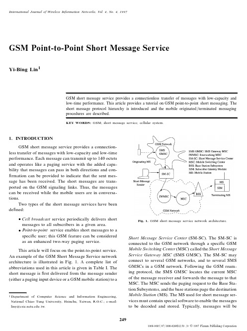
International Journal of Wireless Information Networks, Vol.4, No.4,19971068-9605/97/1000-0249$12.50/01997Plenum Publishing Corporation249GSM Point-to-Point Short Message ServiceYi-Bing Lin 1GSM short message service provides a connectionless transfer of messages with low-capacity and low-time performance. This article provides a tutorial on GSM point-to-point short messaging. The short message protocol hierarchy is introduced and the mobile originated /terminated messaging procedures are described.KEY WORDS:GSM; short message service; cellular system.1. INTRODUCTIONGSM short message service provides a connection-less transfer of messages with low-capacity and low-time performance. Each message can transmit up to 140octets and operates like a paging service with the added capa-bility that messages can pass in both directions and con-rmation can be provided to indicate that the sent mes-sage has been received. The short messages are trans-ported on the GSM signaling links. Thus, the messages can be received while the mobile users are in conversa-tions.Two types of the short message services have been de®ned:Cell broadcast service periodically delivers shortmessages to all subscribers in a given area.Point-to-point service enables short messages to a speci® c user; this GSM feature can be considered as an enhanced two-way paging service.This article will focus on the point-to-poin t service.An example of the GSM Short Message Service network architecture is illustrated in Fig.1. A complete list of abbreviations used in this article is given in Table I. The short message is ®rst delivered from the message sender (either a paging input device or a GSM mobile station) to a1Departmentof Computer Science and Information Engineering,National Chiao Tung University, Hsinchu, Taiwan, R.O.C.; e-mail:liny@ .tw.Fig.1.GSM short message service network architecture.Short Message Service Center (SM-SC). The SM-SC is connected to the GSM network through a speci® c GSM Mobile Switching Center (MSC) called the Short Message Service Gateway MSC (SMS GMSC). The SM-SC may connect to several GSM networks, and to several SMS GMSCs in a GSM network. Following the GSM roam-ing protocol, the SMS GMSC locates the current MSC of the message receiver and forwards the message to that MSC. The MSC sends the paging request to the Base Sta-tion Subsystem s, and the base stations page the destination Mobile Station (MS). The MS used for short message ser-vices must contain special software to enable the messages to be decoded and stored. Typically, messages will beLin 250Table I.Acronym ListCM-Sub: Connection Management SublayerGMSC: Gateway MSCHLR: Home Location RegisterIMSI: International Mobile Subscriber IdentityIWMSC: Interworking MSCLA: Location AreaMAP: Mobile Application PartMM: Mobility ManagementMO: Mobile OriginatedMS: Mobile StationMSC: Mobile Switching CenterMSISDN: Mobile Station ISDN NumberMT: Mobile TerminatedRR: Radio ResourceRPDU: Relay Protocol Data UnitSM-AL: Short Message Application LayerSMC: Short Message ControlSM-CP: Short Message Control ProtocolSMI: Short Message Identi®erSMR: Short Message RelaySM-RL: Short Message Relay LayerSM-RP: Short Message Relay ProtocolSMS: Short Message ServiceSM-SC: Short Message Service CenterSM-TL: Short Message Transfer LayerSS7: Signaling System Number7TCAP: Transaction Capabilities Application PartTPDU: Transfer Protocol Data UnitTP-UD: Transfer Protocol User DataVLR: Visitor Location Registerstored on the Subscriber Identity Module of the MS, which can be displayed on the standard screen of the MS.An MS may send or replay a short message. The message is delivered to a Short Message Service Inter-working MSC(IWMSC) and then to the SM-SC (the details will be elaborated later).2. SMS PROTOCOL HIERARCHYFigure2illustrates the SMS protocol hierarchy for mobile originated messaging [6]. (The architecture for mobile terminated messaging is similar, with the excep-tion that the IWMSC is replaced by the GMSC.)In this hierarchy, the protocol between the IWMSC and the SM-SC below the transfer layer is not speci®ed in GSM.Some example protocols are described in ref.2. Other potential protocols include Telocator Alphanu-meric Input Protocol [7] and Telocator Data Protocol [10]. The protocol between the MSC and IWMSC is GSM MAP[4],which utilizes the services provided by Signaling System Number7Transaction Capabilities Application Part(SS7TCAP) [9,4].The layers below the CM-sublayer are the Mobil-ity Management(MM) Sublayer and the Radio Resource (RR)management sublayer.At the RR-sublayer,the short message service is supported by a control channel (such as SDCCH or SACCH). The upper layer protocols are described below.2.1. The Short Message Transfer LayerThe Short Message Transfer Layer(SM-TL) pro-vides services to transfer Short Message Application Layer(SM-AL) short messages and the corresponding delivery reports [3]. These service primitives (between SM-TL and SM-AL) generate a reference number called Short Message Identi®er(SMI) for every short message associated with the primitives. This SMI at the MS is not carried between the peer entity at the SM-SC. That is, a short message may have different SMIs at the MS and the SM-SC sides.The SM-TP consists of four types of Transfer Pro-tocol Data Units(TPDUs):Fig.2.SMS MS-MSC protocol hierarchy (mobile origination).GSM Point-to-Point Short Message Service251SMS-SUBMIT conveys a short message (UserData or TP-UD) from the MS to the SM-SC. ThisTPDU optionally speci®es the validity period thatthe short message can be buffered in the SM-SCif it cannot be delivered to the recipient immedi-ately.SMS-DELIVER conveys a short message fromthe SM-SC to the MS. This TPDU includes theservice center time stamp used by the SM-SC toinform the recipient MS about the arrival time ofthe short message at the SM-TL of the SM-SC.A Boolean parameter More-Message-To-Send isused to indicate if one or more messages are wait-ing in the SM-SC to be delivered to the recipientMS.SMS-STATUS-REPORT conveys a report fromthe SM-SC to the MS to describe the status of theprevious sent mobile originated short message. Ifthe previous short message is not delivered suc-cessfully, this TPDU may report permanent errors(such as validity period expiration or incompati-ble destination) or temporary errors (such as con-gestion). This TPDU is optionally initiated by theSMS-SUBMIT.SMS-COMMAND conveys a command from theMS to the SC. The command can be a query aboutthe previous submitted short message, cancella-tion of the status report, or deletion of the sub-mitted message.The TPDUs (except for SMS-STATUS-REPORT) have a protocol identi®er that identi®es the layer protocol above SM-TL.For an unsuccessful delivery due to the temporary absence of the MS,messages-waiting information may be stored in the HLR/VLR of the recipient MS. The TPDUs are of either priority of nonpriority. A nonpri-ority TPDU will not be attempted if the MS is absent.2.2. The Short Message Relay LayerThe Short Message Relay Layer(SM-RL)pro-vides services to transfer TPDUs and the correspond-ing delivery reports for SM-TL. These service primitives (between SM-RL and SM-TL) generate SM-RL SMI for every short message associated with the primitives. Sim-ilar to the SM-TL SMI, the SM-RL SMI at the MS is not carried between the peer entity at the SM-SC. For every short message, the SM-RL SMI is mapped to and from the SM-TL SMI.At this layer, the Short Message Relay(SMR) entity at the MS communicates with the peer SMR at the MSC by using the Short Message Relay Protocol(SM-RP). SM-RP is the protocol for the networking func-tions between MS and SM-SC, which interworks with TCAP/MAP in the MSC.SM-RP consists of the following Relay Protocol Data Unit(RPDU) types:RP-DATA is invoked by the SM-RL-DATA ser-vice primitive, which passes the TPDU and neces-sary control information from the MS to the net-work (or from the network to the MS).RP-DATAcontains the originating address (MS or SM-SC),the terminating address (SM-SC or MS), and theuser data containing TPDU.RP-SM-MEMORY-AVAILABLE is invoked bythe SM-RL-MEMORY-AVAILABLE primitive,which passes the necessary control informationfrom the MS to the network to indicate that theMS has memory available to receive one or moreshort messages.RP-ACK is invoked by the SM-RL-REPORTprimitive to acknowledge the corresponding RP-DATA or RP-SM-MEMORY-AVAILABLE.RP-ERROR is invoked by the SM-RL-REPORTprimitive to report error of a corresponding RP-DATA. An error may occur because the messageis too short to contain a complete message typeinformation (and the message should be ignored[5]), the message reference is unknown, the mes-sage type is unknown, or the message content issemantically incorrect.2.3. The Connection Management SublayerThe Connection Management Sublayer(CM-Sub) for SMS provides services to support the SM-RL. In this layer, the Short Message Control(SMC) entity at the MS communicates with the peer SMC at the MSC by using the Short Message Control Protocol(SM-CP). The MS has two SMC entities, one handles MS originated (MO) short message service, and the other handles MS termi-nated (MT) short message service. Note that the SMC entities cannot simultaneously perform messaging in the same direction.The SM-CP consists of the following protocol ele-ments:CP-DATA is invoked by the SM-CP serviceLin 252Fig.3.Mobile originated short messaging (I).primitives MNSMS-DATA or MNSMS-ESTab-lish, which delivers RPDU between the MS andthe MSC.CP-ACK acknowledges the corresponding CP-DATA. The CP-ACK does not contain any spe-ci® c information element.CP-ERROR is invoked by the SM-CP ser-vice primitives MNSMS-ABORT or MNSMS-ERROR, which provides the error cause of themessaging procure.Note that before any CP message is delivered, an MM-connection must be established. The SMC uses the MNSMS-ESTablish primitive to establish an MM-con-nection and then transfer a RPDU on that MM-connec-tion. (Note that the primitives with pre®x MNSMS are between SMC and SMR as indicated in Fig. 3.The primitives between SMC and MM are pre®xed with MMSMS.) The SMC uses the MNSMS-DATA primi-tive to transfer an RPDU on an already established MM-connection. When the short message delivery is com-pleted, the MM-connection is released by the SMC using the MNSMS-RELease service primitive.In abnormal cases (e.g., RR-connection failure or SM-CP protocol error), the SMC releases an MM-connection by using the MNSMS-ABORT service primitive. When an error occurs (the causes are similar to that reported by RP-ERROR), the SMC releases an MM-connection by using the MNSMS-ERROR service primitive.3. MOBILE ORIGINATED MESSAGINGIn mobile originated(MO)messaging,the MS sends a short message to the SM-SC. Depending on the destination of the message, the SM-SC may deliver the message to another MS or to a normal pager through the traditional paging system [8]. Figure3illustrates the message ¯ow for MO messaging. The logical message path is MS>originating MSC>IWMSC>SM-SC (note that the originating MSC can be the IWMSC). The procedure is described in the following steps: Step1.The SM-TL entity issues an SMS-SUBMIT TPDU to the SM-RL by the SM-RL-DATA(Request) primitive.Step2.The SMR entity creates an RP-DATA(MO) RPDU and invokes the MNSMS-ESTablish(Request) primitive to transfer the RPDU. The SMR sets the timer TR1M and expects to receive the RP-ACK before the timer expires. If the timer expires, the CM-connection (and thus the MM-connection) is aborted, and a report indication is passed to SM-TL.Step3.The SMC rst establishes the MM-connec-tion as illustrated in Fig.4.Step3a.The MS sends a CM SERVICE RE-QUEST message to the MSC. The service type of this message is `short message service.’Fig.4.MM-connection establishment for mobile originated short mes-saging.GSM Point-to-Point Short Message Service253 Step3b.The SMS coordinating process in theMSC (Co SMS MSC) is invoked, which sends theMAP PROCESS ACCESS REQUEST messageto the VLR. This message (and the messages withpre®x MAP) is GSM MAP message that is deliv-ered through the SS7network by using the SS7TCAP protocol.Step3c.The VLR checks if the MS is legal toreceive the short message service. If so, it acknowl-edges the MSC request.Step3d.The MSC forwards the acceptanceto the MS by sending the message CM SER-VICE ACCEPT.Step4.After the connection to the MSC is estab-lished, the SMS creates the CP-DATA containing the RPDU, and sends the message to the MSC. It sets a timer TC1*and expects to receive the result before the timer expires. The value of the timer may vary with the length of CP-DATA and the type of the radio channel (SDCCH or SACCH) used for the transmission. If TC1*expires, the CP-DATA message may be retransmitted for at most three times. If the attempt is not successful, then the error is reported to SM-RL, and the CM-connection is released.Step 5.The MSC acknowledges the CP-DATA message by returning a CP-ACK. When the SMC of the MS receives the CP-ACK, the TC1*timer is reset.Step 6.The SMS-SUBMIT request is forwarded from the SMR entity to the SM-TL of the MSC by the MNSMS-ESTablish(Indication) and the SM-RL-DATA-(Indication) primitives. The SMR sets the timer TR2N and expects to receive the SMS-STATUS-REPORT (Step13) before the timer expires. If the timer expires, the SMR requests the SMC to abort the CM-connection (and thus the MM-connection). It also sends a report indication to the SM-TL. (Note that the transfer layer protocol only involves the MS and the SM-SC.) Step7.(See Fig. 5.)After the MSC receives the TPDU,the mobile originated short message ser-vice process in the MSC(MOSM MSC)is invoked. The MOSM MSC sends the MAP SEND INFO FOR MO SMS message to the VLR to request the subscriber-related information (e.g., the MSISDN of the MS). This message is used to check if the request violates supple-mentary services invoked or any restrictions imposed.Step8.The VLR either acknowledges the requestpositively or provides the following error causes: Tele-service is not provisioned, call barred, unexpected datavalue, or data missing.Step9.If the VLR response is positive, then theMSC sends the GSM MAP message MAP FORWARDFig.5.Mobile originated short messaging (II). SHORT MESSAGE to the IWMSC (the gateway tothe SM-SC). Note that if the MSC is the IWMSC, thenthis message is saved. The message includes the SM-SC address (provided by the MSC; the address is an E.164number [1]), the sender’s MSISDN, and the short mes-sage (i.e., the TPDU).Steps10±12.The short message is delivered to theSM-SC,and the SM-SC returns a delivery report to the IWMSC. This report is included in the GSM MAPmessage MAP FORWARD SHORT MESSAGE ack sent from the IWMSC to the MSC.Steps13and14.(See Fig.6.) The SM-TL entitysends SMS-STATUS-REPORT to the SMR entity at SM-RL, and the TR2N timer is stopped. The SMR gener-ates RP-ACK and sends it to SMC at CM-Sub. The SMR also releases the CM-connection (and thus the MM-con-nection).Step15.The SMC entity generates the CP-DATA and sends it to the MS. The TC1*is set as in Step4.Step16.When the SMC entity of the MS receivesthe CP-DATA, it forwards the RP-ACK to the SMR en-tity at the SM-RL. It also sends the CP-ACK to the MSC.Step17.The SMR stops the TR1M timer, forwards SMS-STATUS-REPORT to SM-TL, and invokes the MNSMS-RELease primitive to release the CM-connec-tion.Step18.The CM-connection and the MM-connec-tion are released. If the short message transfer is not suc-cessful, the status report provides the error cause to the MS. The error can be unknown service center address, service center congestion, invalid short message entity address, subscriber not service center subscriber, or pro-tocol error.Note that the MO messaging procedure is similar tothat for GSM call origination [4], with one major differ-Lin 254Fig.6.Mobile originated short messaging (III).ence. MO messaging needs IWMSC to interwork to SM-SC. On the other hand, in GSM call origination, the orig-inating MSC processes the call request just like a typicalcentral of®ce in the public switched telephone network.4. MOBILE TERMINATED MESSAGINGIn mobile terminated(MT)messaging,an MSreceives a short message from the SM-SC. The messagesender can be another MS in the GSM network or aninput device in the traditional paging system. The logi-cal message path is SM-SC>GMSC>terminatingMSC>MS where the GMSC can be the terminatingMSC. Figure7illustrates the message ¯ow for MT mes-saging. Note that in this procedure, the GMSC needs toquery the HLR to locate the terminating MSC. The pro-cedure is described in the following steps:Steps1and2.The SMS GMSC receives a shortmessage(RP user data)from the SM-SC.The SMSGMSC requests the routing information by sending themessage MAP SEND ROUTING INFO FOR SM tothe HLR. The message includes the MSISDN of the re-cipient MS.Step 3.The HLR uses the received MSISDN toretrieve the routing information of the MS. The HLRreturns MAP SEND ROUTING INFO FOR SM ackto the SMS GMSC. If the operation fails, then an erroris indicated in the message. The error causes are simi-lar to the ones listed in Step8of the MO messaging.If the operation is successful, then the message includesthe IMSI and the serving MSC address of the recipientMS.Step4.The SMS GMSC delivers the short mes-sage to the MSC by sending the message MAP FOR-WARD SHORT MESSAGE.This message is de-scribed in Step9of MO messaging, with one majorexception. In MT messaging, the message should spec-ify the More-Messages-To-Send parameter to indicate ifthere are more messages to send. This parameter is notFig.7.Mobile terminated short messaging (I).GSM Point-to-Point Short Message Service 255Fig.8.Mobile terminated short messaging (II).used in MO messaging. Also, the destination address is IMSI in MT messaging.Step 5.The MSC sends MAP SEND INFO FOR MT SMS to the VLR to obtain the subscriber-related information.Step 6.When the VLR receives the message MAP SEND INFO FOR MT SMS , a micro Check Indica-tion is invoked to check the data value of the message.If the tests are passed, the VLR initiates the paging pro-cedure. If the VLR knows the Location Area (LA) of the recipient MS, then MAP PAGE is sent to page the MS in the LA. Otherwise,MAP SEARCH FOR SUB-SCRIBER is sent to page all LAs in the MSC. For sim-plicity, assume that MAP PAGE is sent.Steps 7±9.The MSC performs the paging opera-tion. If the operation is successful, then the MSC sends the MAP PROCESS ACCESS REQUEST message to the VLR.Step 10.The VLR sends MAP SEND INFO FOR MT SMS ack to the MSC, and the MSC is al-lowed to initiate forwarding of the short message to the MS.Steps 11±20.(See Fig.8.)The SMR entity of the MSC generates RP-DATA from the TPDU SMS-DELIVER , and relays it to the MS. These steps are sim-ilar to Steps 1±6and 13±19in MO messaging.Step 21.(See Fig.9)After the MSC receivesFig.9.Mobile terminated short messaging (III).the SMS-STATUS-REPORT ,the result is included in MAP FORWARD SHORT MESSAGE ack to ac-knowledge the message sent in Step 4.Step 22.If the result sent from MSC indicates that the recipient MS is absent,the SMS GMSC may invoke the procedure MAP REPORT SM DE-LIVER STATUS and informs the HLR the status for further processing. The SMS GMSC may take actions for other failures /errors. In any case, it forwards the result to the SM-SC.The MT messaging procedure is similar to GSM call termination [4], with one major difference. In MT messaging, when the HLR is queried by the GMSC, the destination MSC number stored in the HLR is sent back to the GMSC directly. In GSM call termination, the HLR always queries the VLR to obtain the MSC number and the related routing information. Note that the MSC num-ber stored in the VLR is more up to date than that in the HLR. Since a voice call is circuit-switch-oriented andLin 256the voice trunk must be set up from the GMSC to theterminating MSC, accurate routing information must beobtained from the VLR to avoid unnecessary trunk reser-vation due to misrouting. On the other hand, MT messag-ing is circuit-switch-oriented, where trunk setup is notneeded. Thus, the MSC number is obtained directly fromthe HLR to simplify the routable address query proce-dure. If the MSC number is out of date (which is not verylikely), the SMS protocol considers the MS is absent(and Step22is executed).5. CONCLUSIONSThis article provided a tutorial on GSM point-to-point short messaging. The short message protocol hier-archy was introduced and the mobile originated/ter-minated messaging procedures were described.Otherprocedures, such as the memory available noti®cationprocedure, follow the same rules described in the mobileoriginated/terminated messaging and are not covered inthis article. The reader is referred to ref.6. Inter MSChandover may occur during the short message delivery.The details can be found in ref.6. The short messageinformation ¯ow is described at Annex3in ref.3. Arecipient MS can reply a short message as speci®ed atAnnex4in ref.3.ACKNOWLEDGMENTSThe author would like to thank Kaveh Pahlavanand the three reviewers for their valuable comments andassistance in improving the quality of this paper. Thiswork was supported in part by National Science Coun-cil Contract No. NSC86-2213-E-009-074.REFERENCES1. CCITT.Numbering plan for the ISDN era. Technical Report Rec-ommendation E.164(COM II-45-E), ITU-T,1991.2. ETSI/TC.Technical Report Recommendation GSM03.47, ETSI,1993.3. ETSI/TC. Technical Realization of the Short Message ServicePoint-to-Point, Version4.6.0. Technical Report RecommendationGSM03.40, ETSI,1993.4. ETSI/TC.Mobile Application Part(MAP)Speci®cation,Ver-sion4.8.0. Technical Report Recommendation GSM09.02, ETSI,1994.5. ETSI/TC.Mobile Radio Interface Signaling Layer3(Phase2),Version:4.2.0. Technical Report Recommendation GSM04.07,ETSI,1994.6. ETSI/TC.Point-to-Point (PP) Short Message Service (SMS) Sup-port on Mobile Radio Interface, Version:4.5.0. Technical ReportRecommendation GSM04.11, ETSI,1994.7. Glenarye Electronics, IXO TAP Protocol. Technical Report GLP-3000-180, Glenarye Electronics,1991[see also ftp://mirror.lcs./telecom-archiv es/technical/ixo.tap.protocol].8. Y.-B.Lin,Paging systems:A tutorial.Technical Report PCS-NCTU-96-24, Department CSIE, National Chiao Tung University,1996[see also .tw].9. Y.-B.Lin and S. K. DeVries, PCS network signaling using SS7.IEEE Personal Communication s Magazine,Vol.2,No.3,pp.44±55,1995[see also .tw].10. PCIA,Telocator data protocol. Technical Report ttp://www.mot.com/MIMS/MSPG/pcia protocols/tdp,Personal Communica-tions Industry Association, July1995.Yi-Bing Lin received his BSEE degree from National ChengKung University in1983, and his Ph.D. degree in Computer Sciencefrom the University of Washington in1990. From1990to1995, hewas with the Applied Research Area at Bell Communications Research(Bellcore), Morristown, New Jersey. In1995, he was appointed Profes-sor in the Department of Computer Science and Information Engineer-ing (CSIE), National Chiao Tung University (NCTU). In1996, he wasappointed Deputy Director of Microelectronics and Information Sys-tems Research Center, NCTU. In1997, he become Chairman of theCSIE, NCTU. His current research interests include design and analy-sis of personal communications services network, mobile computing,distributed simulation, and performance modeling.Dr. Lin is a subject area editor of the Journal of Parallel andDistributed Computing, an associate editor of the International Jour-nal in Computer Simulation, an associate editor of IEEE Networks,an associate editor of SIMULATION magazine, an area editor of ACMMobile Computing and Communication Review, a columnist of ACMSimulation Digest, a member of the editorial board of InternationalJournal of Communications Systems, a member of the editorial boardof ACM/Baltzer Wireless Networks, a member of the editorial board ofComputer Simulation Modeling and Analysis, Program Chair for the8th Workshop on Distributed and Parallel Simulation, General Chairfor the9th Workshop on Distributed and Parallel Simulation, ProgramChair for the2nd International Mobile Computing Conference, thePublicity Chair of ACM Sigmobile, Guest Editor for the ACM/BaltzerMONET special issue on Personal Communications, Guest Editor forIEEE Transactions on Computers special issue on Mobile Computing,and Guest Editor for IEEE Network special issue on PCS NetworkManagement. Dr. Lin is a senior member of IEEE.。
fulltext 用法
"fulltext" 是一个单词,通常用作名词,指的是包含文本的完整文档或全文。
在不同的上下文中,"fulltext" 可能有不同的用法。
1.数据库搜索:在数据库查询中,"fulltext" 可以表示进行全文检索,而不仅仅是基于关键词或标签的检索。
例如,数据库的 "fulltext search" 功能允许用户搜索文本中的所有单词,而不仅仅是特定字段或标签。
2.搜索引擎:在搜索引擎领域,"fulltext search" 通常指的是对整个文档或网页进行搜索,以找到包含用户查询关键词的文本。
3.编程:在编程中,"fulltext" 可能用于描述支持完整文本搜索或处理的库或工具。
例如,全文搜索引擎库可以被称为 "fulltext search library"。
Mysql索引PRIMARY、NORMAL、UNIQUE、FULLTEXT区别和使⽤场合索引 数据库的索引就像⼀本书的⽬录,能够加快数据库的查询速度。
MYSQL索引有四种PRIMARY、INDEX、UNIQUE、FULLTEXT,其中PRIMARY、INDEX、UNIQUE是⼀类,FULLTEXT是⼀类。
这四种都是单列索引,也就是他们都是作⽤于单个⼀列,所以也称单列索引;但是所以⼀个索引也可以作⽤于多个列上,称为组合索引或复合索引。
单列索引 新建⼀张测试表CREATE TABLE T_USER( ID INT NOT NULL,USERNAME VARCHAR(16) NOT NULL); (1)PRIMARY:主键索引。
索引列唯⼀且不能为空;⼀张表只能有⼀个主键索引(主键索引通常在建表的时候就指定)CREATE TABLE T_USER(ID INT NOT NULL,USERNAME VARCHAR(16) NOT NULL,PRIMARY KEY(ID)) (2)NORMAL:普通索引。
索引列没有任何限制;建表时指定CREATE TABLE T_USER(ID INT NOT NULL,USERNAME VARCHAR(16) NOT NULL,INDEX USERNAME_INDEX(USERNAME(16))) //给列USERNAME建普通索引USERNAME_INDEX ALTER语句指定ALTER TABLE T_USER ADD INDEX U_INDEX (USERNAME) //给列USERNAME建普通索引 U_INDEX删除索引DROP INDEX U_INDEX ON t_user //删除表t_user中的索引U_INDEX(3)UNIQUE:唯⼀索引。
索引列的值必须是唯⼀的,但允许有空;建表时指定CREATE TABLE t_user(ID INT NOT NULL,USERNAME VARCHAR(16) NOT NULL,UNIQUE U_INDEX(USERNAME)) //给列USERNAME添加唯⼀索引T_USERALTER语句指定ALTER TABLE t_user ADD UNIQUE u_index(USERNAME) //给列T_USER添加唯⼀索引u_index删除索引DROP INDEX U_INDEX ON t_user (4)FULLTEXT:全⽂搜索的索引。
navcat mysql fulltext 用法在MySQL 中,FULLTEXT是一种用于全文搜索的索引类型,它可以让你执行更复杂和更灵活的文本搜索操作。
在使用FULLTEXT索引之前,需要确保表的存储引擎是MyISAM 或InnoDB。
以下是使用FULLTEXT索引的基本用法:1.创建FULLTEXT 索引:首先,需要在表的一个或多个列上创建FULLTEXT索引。
例如,如果有一个名为content的列需要进行全文搜索:ALTER TABLE your_table ADD FULLTEXT index_name (content);这样就在content列上创建了名为index_name的FULLTEXT 索引。
2.执行全文搜索:创建了FULLTEXT索引后,可以使用MATCH ... AGAINST语法执行全文搜索。
例如:SELECT * FROM your_table WHERE MATCH(content)AGAINST('search_term');这将返回包含search_term的行,content列与搜索条件匹配。
3.指定搜索模式:可以指定全文搜索的模式,例如BOOLEANMODE或NATURAL LANGUAGE MODE。
默认模式是NATURAL LANGUAGE MODE。
例如:SELECT * FROM your_table WHERE MATCH(content)AGAINST('search_term' IN BOOLEAN MODE);4.限制搜索结果数量:可以使用LIMIT限制返回的搜索结果数量。
SELECT * FROM your_table WHERE MATCH(content)AGAINST('search_term') LIMIT 10;5.排除特定词:可以使用-符号排除包含特定词的行。
SELECT * FROM your_table WHERE MATCH(content)AGAINST('+search_term -excluded_term');需要注意的是,FULLTEXT索引在执行全文搜索时只能用于MyISAM 或InnoDB 存储引擎,并且只能应用于CHAR、VARCHAR或TEXT类型的列。
Drug Information Fulltext药物信息全文数据库数据来源: American Society of Health-System Pharmacists(ASHP) 美国药剂师协会_____________________________________Drug Information Fulltext是一个收录广泛,客观评价的药物信息数据库。
该数据库收录有目前美国所有可用的分子药物的信息。
Drug Information Fulltext (DIFT) 收录来自逾2000本药物学专著的约110,000种目前在美国市场上通行的药物的信息。
DIFT由2个独立的子库组成,AHFS药物信息数据库和静脉注射药物手册。
AHFS药物信息数据库首次出版于1959年,被人们称作“大红书”而广为人知,致力于为药剂师和卫生保健专业人员提供最详细的问题答案。
迄今为止,AHFS药物信息数据库是全球收录循证信息最多的药学数据库。
该数据库完全辟除药物生产商,保险公司,管理者以及其他商业影响,为读者提供客观公正,经过严格测试和证实的药物信息。
AHFS涵盖以下主题:1 美国食品及药物管理局(FDA)批准使用或者禁用的药物之最新评论2针对药物的相互作用,用法和毒性的全面分析3 有关药物剂量和管理办法的详细信息4 知名实验室对于药物的调查报告和检测结论5 药物化学性和稳定性的调查报告6药理学和药物代谢动力学7常见处方药, OTC药物,眼科和皮肤科药物的完全清单列表,甚至包括维生素药物和肠外营养药物。
8逾70,000笔被引用的参考信息。
除了多功能性之外,AHFS数据库还是目前最获普遍承认的顶尖药物参考资源。
有全球顶尖药剂师撰写的信息并通过逾500位药学界专家的评审,AHFS所收录的信息为药学研究人员提供不可或缺的珍贵学术资源。
-----------------------------------------------------------------------------Drug Information Fulltext的第二部分重要组成是静脉注射药物手册。
Evaluation of polyethersulfone highflux hemodialysis membrane in vitro and in vivoBai-hai Su ÆPing Fu ÆQiu Li ÆYe Tao ÆZi Li ÆHui-sha Zao ÆChang-sheng ZhaoReceived:17July 2006/Accepted:15March 2007/Published online:10July 2007ÓSpringer Science+Business Media,LLC 2007Abstract A new hemodialysis membrane manufactured by a blend of polyethersulfone (PES)and polyvinylpyrr-olidone (PVP)was evaluated in vitro and in vivo.Goat was selected as the experimental animal.The clearance and the reduction ratio after the hemodialysis of small mole-cules (urea,creatinine,phosphate)for the PES membrane were higher in vitro than that in vivo.The reduction ratio of b 2-microglobulin was about 50%after the treatment for 4h.The biocompatibility profiles of the membranes indi-cated slight neutropenia and platelet adhesion at the initial stage of the hemodialysis.Electrolyte,blood gas,and blood biochemistry were also analyzed before and after the treatment.The results indicated that PES hollow fiber membrane had a potential widely use for hemodialysis.IntroductionHollow fiber membranes are widely used in blood purifi-cation,such as hemodialysis,hemofiltration,plasma sepa-ration,and membrane oxygenation.Among them,hemodialysis is a widely used treatment modality for kid-ney failure.The treatment is intermittent,generally three times weekly for periods between 3and 5h depending upon the patient clinical requirements.The first hollow fiber hemodialyzers were used clinically in the 1960s [1,2],and the material of the hollow fiber membrane is unmodified cellulose.Cellulose membranes are still widely used for hemodialysis because their hydrogel structure and small thickness provide very effective removal of small solutes like urea and creatinine.However,these mem-branes provide relatively little clearance for ‘‘middle’’molecules like b 2-microglobulin that is known to be associated with many dialysis-related disorders.In addi-tion,the cellulosic structure contains a high density of hydroxyl groups,which are known to cause complement activation upon contact with blood [3].The shortcomings in cellulose membranes have led to the development of hemodialyzers based on a variety of synthetic polymers and modified cellulosic materials,including polysulfone (PSF),polyamide (PA),polyacrylo-nitrile (PAN),cellulose triacetate (CTA),and Hemophan (HP).Among the materials,PSF is one of the most important polymeric materials and is widely used;PSF-based membranes show outstanding oxidative,thermal,and hydrolytic stability as well as good mechanical and film-forming properties.The PSF membranes also showed high permeability for low molecular weight proteins when used for hemodialysis.The commercial product of PSF hollow fiber hemodialyzer was produced by Germany (Fresenius Polysulfones,Fresenius Medical Care,Bad Homburg,B.-h.Su ÁC.-s.Zhao (&)College of Polymer Science and Engineering,State Key Laboratory of Polymer Materials Engineering,National Engineering Research Center for Biomaterials,Sichuan University,Chengdu 610065,P.R.Chinae-mails:zhaochsh70@;zhaochsh70@ B.-h.Su ÁP.Fu ÁY.Tao ÁZ.Li ÁH.-s.ZaoDepartment of Nephrology,West China Hospital,Sichuan University,Chengdu 610041,P.R.China Q.LiDepartment of Ultrasound,West China Hospital,Sichuan University,Chengdu 610041,P.R.China C.-s.ZhaoChengdu OCI Medical Device Co.,Ltd,Chengdu 610025,P.R.ChinaJ Mater Sci:Mater Med (2008)19:745–751DOI 10.1007/s10856-007-3006-9Germany),and was widely acknowledged as providing an optimal biocompatibility in terms of solute removal and complement activation[4,5].PSF can also be used as bone joint screws due to its biostable[6].Polyethersulfone(PES)is a parent material of PSF,with a better chemical resistance,thermal stability,mechanical properties as well as a better hydrophilicity compared to PSF.The PES plasma separation membrane was evaluated by animal experiments,and showed good blood compati-bility[7].In the present study,we prepared a new hollow fiber dialysis membrane by blending PES and polyvinyl-pyrrolidone(PVP),and then evaluated the performance of the membrane in vitro and in vivo.Goat was selected as the experimental animal.Experiments were performed to evaluate the solute clearance and the blood compatibility. Materials and methodsPES hemodialyzerThe PES hollowfiber membrane hemodialyzer was pre-pared by us.Both PES(BASF Aktiengesellschaft)and PVP (PVP-90K,BASF Aktiengesellschaft)were dissolved in N,N-Dimethyl acetamide(DMAc,Chengdu Chemical Reagent,Inc.,China)to obtain the spinning solution.The hollowfiber was spun by the dry–wet spinning method[8], based on a complex process involving phase inversion or precipitation.The specifications of the hemodialyzer are shown in Table1.For scanning electron microscopy(SEM)observation, the hollow membrane samples were broken in liquid nitrogen,attached to the sample supports and coated with a gold layer.The SEM images were recorded using an S-2500C microscope(voltage=20kV,Hitachi,Japan). Hemodialysis using a simulation solutionThe test solutions were prepared according to the interna-tional standard ISO8637[9].The molar concentrations of urea,creatinine,and phosphate in the simulation solution were15mmol/L,500l mol/L,and1mmol/L,respec-tively.The test procedure was accordant to the procedure in ISO8637.The ultra-filtration coefficient was calculated as the unit mL/mmHg h.The clearance(K)of small mol-ecules(urea,creatinine,phosphate)were established by sampling from the inlet and outlet segments of the extra-corporeal circuit1h after the initiation of the treatment, and was calculated using the following formula.K¼C BIÀC BOC BIQ BIþC BOC BIQ Fwhere C B is the solute concentration in the blood(here is the simulation solution);I,O refer to the inlet and the outlet to the device;Q BI is the bloodflow rate at the dialyser inlet; Q F is thefiltration rate.Urea was determined by a reagent Kit for Urea Deter-mination(Diethyl-Monoxime,Beijing chemical regent factory,China);creatinine was quantified by the absorption at235nm using an UV–Vis spectraphotometer U-200A (Hitachi Co.,Ltd.,Tokyo,Japan)through a standard curve. Phosphate was determined using the molybdate blue method:phosphate reacts with ammonium molybdate and is then reduced by stannous chloride to form a blue com-plex,and then measured at670nm with the UV–VIS spectraphotometer U-200A.Hemodialysis using pig blood in vitroPig fresh blood was collected using a glass tank,containing citrate/phosphate/dextrose/adenine-1mixture solution (CPDA-1)as an anticoagulant(anticoagulant to blood ratio,1:7).The dialysis procedure was the same as the Sect.‘‘Hemodialysis using a simulation solution’’,and the solute clearance was calculated using the same formula as described in the Sect.‘‘Hemodialysis using a simulation solution’’.The concentrations of urea,creatinine,and phosphate were determined using an Auto Biochemistry Analyzer7170A(Hitachi Co.,Ltd.,Tokyo,Japan). Hemodialysis in vivoThree adult hybrid goats weighing about20kg were used in the experiment.All animals underwent local anesthesia with1.0%procaine hydrochloride by injection into the neck muscle.The hair on the neck was cleared away carefully.The animal was laid on its back andfixed on the experimental table.Extracorporeal circuits were primed with500mL nor-mal saline solution to remove the bubbles in the circuits and in the dialyzer,then primed with500mL saline solution containing10,000IU heparin.About150mg urea and50mg creatinine were injected to the animal blood before the treatment.At the initiation of the treatment goats received a loading dose(3,000IU)of heparin,andTable1Specifications of the PES hemodialyzerHollowfiberInternal diameter(l m)205Wall thickness(l m)50Effective length(mm)240 Membrane area(m2) 1.5Potting material Polyurethane Sterilized method c-rayfollowed by continuous infusion (3,000IU/h).The infusion was terminated at 30min prior to the end of the dialysis.Extracorporeal circuits with left–right neck intravenous cannulation were created on the animal using B.Braun blood tubing lines for hemodialysis.The clearance (K )of small molecules (urea,creatinine,phosphate)were estab-lished by sampling between the inlet and outlet segments of the extracorporeal circuit 1h after the initiation of the treatment,and was calculated using the formula described in Sect.‘‘Hemodialysis using a simulation solution’’.The fluid removal rate during these measurements was main-tained at (3mL/min).The levels of urea,creatinine,phosphate,total proteins (TP),albumin (ALB),alanine aminotransferase (ALT),aspartate aminotransferase (AST),and alkaline phospha-tase (ALP)were determined using an Auto Biochemistry Analyzer 7170A (Hitachi Co.,Ltd.,Tokyo,Japan).Removal of b 2-microglobulin was established from the changes in plasma b 2-microglobulin levels during the treatment at different time intervals (30,60,120,180,and 240min).Plasma b 2-microglobulin levels were determined using a commercially produced ELISA assay (Cambridge Life Sciences,Cambridge,UK).Electrolyte levels were determined before and after hemodialysis.K +,Na +,and Cl –were determined using electrolyte analyzer (NOVA CRT-4,US),and Ca 2+was determined using an Auto Biochemistry Analyzer 7170A (Hitachi Co.,Ltd.,Tokyo,Japan).Blood cells including red blood cell (RBC)and white blood cell (WBC),and blood components including hemoglobin (HGB)and platelet were determined using a blood cell analyzer (BC-3000peus,Shenzhen Mairui Bio-medical Device Co.Ltd.,China).Blood gas was deter-mined using a blood gas analyzer (CORNing 238,US).For complement and WBC activation investigation,various membranes were used from different companies,Cuprophane (Nephross,Netherlands),Cellulose acetate (Nissho,Japan),Hemophane (Ningbo-Yatai,China),Polysulfone (PSF,Fresenius,Germany).Polycarbonate (PC)was obtained from BASF Co.Ltd.,and the PC membrane was prepared in our plement C3activation was determined in vitro by enzymelinked immunosorbent assays (ELISA)[10].For comparing the results,activation for Cuprophane membrane was used as control.ResultsMorphology of the PES hollow fiber membraneFigure 1shows the SEM images of the cross-section of the PES hollow fiber membrane used to prepare the hemodi-alyzer.As shown in the figure,the pore structure of the fiber was a figure-like structure that started from the inner edge of the fiber and went through the whole cross-section.And a skin layer with a thickness of about 3l m was found at the internal surface of the hollow fiber.The skin layer and the figure-like structure were useful for using as blood purification membrane.Additionally,from the SEM pictures for the internal surface and the outer surface (data not shown),we could found that there was no visible pores at the inner edge of the fiber at a magnifica-tion of 10,000·,while there was a network of pores of 0.3l m at the outer edge.Solute transportTable 2summarizes the clearance data and the reduction ratio after the dialysis for small molecules in vitro and in vivo.It was clearly that the clearances and the reduction ratios for all the solutes were larger using the simulated solution than that for blood.Changes in b 2-microglobulin during the dialysis for the goats are plotted in Fig.2.The reduction ratio was about 50%after the treatment for 4h.The ultrafiltration coefficient was obtained by the hemodialysis process using the simulated solution with a value of 81mL/h mmHg,from which we can conclude that the PES membrane was a high-flux hemodialysis mem-brane.The removal of small molecules during dialysis is governed by hydrodynamic conditions within the dialyser rather than membrane structure since the majorresistanceFig.1SEM images of the PES hollow fiber membraneto transport from the blood into the dialysisfluid lies not in the membrane but boundary layers adjacent to the mem-brane.Thus,the data of clearance and the reduction ratio (Table2)for the simulated solution were higher than that for the blood due to the proteins in the blood,which may induce concentration polarization.The PES membrane was able to reduce the plasma burden of b2-microglobulin during the treatment are shown in Fig.2.The data were analyzed by consideration of actual values and the percentage reductions achieved.The reduction ratio was about50%after the treatment for4h, this value is comparable compared to that for PSF mem-brane and polyflux[4].More recently,clinical study was performed to compare the PSF and the PES membrane,the b2-microglobulin reduction ratios were51.70±15.75and 53.13±20.41,respectively(p=0.52).Table3shows the electrolyte values in the goat blood before and after the dialysis process.Among the these ions,only the K+exhibited statistically significant decreases after the dialysis,whereas Na+,Cl–and Ca2+did not change. BiocompatibilityFigure3summarizes the changes in the goat blood ob-served during the dialysis in respect of white cells(WBC) and platelets.Both WBC and platelet counts have been normalized to pretreatment levels and expressed as a per-centage of these values.A small decline in both was noted at thefirst30minutes,and returned to the initial levels after about2h.The complement and WBC activation for various membranes were investigated after contacting to blood for 1h,as shown in Table4.The data show the correlation between the complement and WBC activation.We also found that the concentration of C3a increased rapidly at the beginning of the contact between the blood and the PES membrane and remained constant after90min,which was consistent with the decrease of WBCs[7].Hemolysis ratio was also determined for the pig blood in vitro and for the goat blood in vivo.Data showed that there was only a slightly hemodialysis phenomena(about1.7%) in vitro,while the hemolysis ratio was zero in vivo(The absorption value for(+)is0.832,but for the sample is0).The RBC and hemoglobin(RGB)levels were also determined during the dialysis.The RBC was(2.04±0.12)·1012/L and(1.96±0.10)·1012/L respectively before and after the hemodialysis.And the HGB was 115.0±8.0and110.5±8.0g/L before and after the hemodialysis,respectively.Biochemistry for the blood was analyzed before and after the hemodialysis,and the data were summarized in Table5.Only the ALP level increased.And the others, including ALT,AST,TP and plasma albumin(ALB)were slightly decreased.The blood gas was also analyzed as shown in Table6.And the data showed no statistically change during the dialysis.The urine solution was also analyzed before and after the hemodialysis,the pH value, urine protein and urine glucose had no change before and after the hemodialysis.The concentrations of urobilinogen were3.5and3.7mmol/L before and after the hemodialy-sis,respectively.Table2Small molecular clearance at a blood(or simulated solution)flow rate of180mL/min and dialysateflow rate of500mL/minClearance(mL/min)Reduction ratio(%)Urea Creatinine Phosphate Urea CreatinineSimulated solution174.0±6.0169.0±5.0170.0±6.094.3±3.892.4±4.1 Blood in vitro157.5±7.4143.6±6.8144.5±7.271.2±3.969.9±4.0 Blood in vivo153.6±9.4141.6±8.2142.5±7.369.2±4.568.9±5.2Data are expressed as the means±SD,n=3Table3Electrolyte values pre-and post-dialysisPre-dialysis Post-dialysisK+(mmol/L) 3.71±0.37 2.98±0.17Na+(mmol/L)144.0±3.8142.8±1.8Cl–(mmol/L)105.1±4.1101.0±1.2Ca2+(mmol/L) 2.12±0.16 2.02±0.11Data are expressed as the means±SD,n=3Discussion PES membraneSynthetic membranes are manufactured by blending of normally hydrophobic polymers with hydrophilic materials to make them suitable for use in renal replacement therapy.As we know,hydrophobic polymer membrane surface adsorb much more proteins from plasma when they come into contact with blood [11–13],and this is so-called ‘‘membrane fouling,’’which can induce flux decrease.The blending of hydrophilic polymer materials is one practical approach to modify hydrophobic membrane surface.To modify PSF and PES membrane,PVP is usually blended into them to increase the hydrophilicity of the resultant membranes.The commercial product of PSF hollow fiber membrane produced by Germany was modi-fied by blending of PVP.Qin et al.[14]prepared PES/PVP blended hollow fiber membranes with enhanced flux for humic acid removal.Hoenich et al.[4]evaluated the clinical performance of a hemodialysis membrane manu-factured from a blend of polyamide,polyarylethersulfone and PVP.Huang et al.[15]evaluated two high-flux dia-lyzers,dialyzer A (cellulose triacetate)and dialyzer B (PES),in the study water solution with urea and creatinine were made as ‘‘blood,’’and pure water was used as dial-ysate.Gerdemann et al.[16]studied the advanced glyca-tion end products (AGEs)removal by high-flux dialysis;they used a DIAPES membrane prepared from PES,which was similar to the PES membrane in our study.The dif-ference was the ultra-filtration coefficient,in this study the ultra-filtration coefficient is 81mL/mmHg h,while that for the DIAPES membrane was 35mL/mmHg h.The higher ultra-filtration coefficient indicated that higher water removal rate could be obtained,but the plasma protein level was not significantly decreased as mentioned above.These could contribute the higher molecular weight of PVP used in this study,which significantly increased the hydrophilicity of the membrane.However,the elution of the blended hydrophilic polymer should be noticed.Thus,the molecular weight of the hydrophilic polymer and the miscibility of the two polymers are important when we prepare the membranes.In this study,we chose one kind of PVP with high molecular weight (PVP-90K,BASF,Germany)to modify PES.The resultant PES membrane has an increased hydrophilicity,the contact angle decreased to about 30°,and correlated to the PVP amount.The dynamic contact angle decreased with time.Also,when high molecular weight PVP was used,the PVP is stable in the membrane compared to low molecular weight ones PVP-30K,this can be easily testified by incubating the membranes in normal saline solutions.The PES hollow fiber membrane was prepared using a dry-wet spinning method based on the common phase inversion and precipitation technique,and has an inner skin as shown in Fig.1.The inner skin layer was obtained when a strong coagulant,water was used as a bore liquid to speed up the instantaneous phase separation from the inner surface of the nascent fiber and at the meantime the phase separation at the outer surface was delayed by the air gap [14].Table 4Complement and WBC activation for various membranes Membrane Complement activation (%)WBC activation (%)Cuprophane 100100Cellulose acetate 6743Hemophane 6062Polycarbonate 4053PSF 2715PES2412Table 5Data for biochemistry analysis pre-and post-dialysisPre-dialysisPost-dialysis ALT (IU/L)29.0±3.026.5±1.5AST (IU/L)189.5±9.5173.0±15.5ALP (IU/L)284.0±33.0266.0±13.0TP (g/L)70.2±1.463.8±1.8ALB (g/L)29.2±0.427.6±0.4Data are expressed as the means ±SD,n =3Table 6Blood gas values pre-and post-dialysisPre-dialysisPost-dialysis pH 7.43±0.07.47±0.02PCO 2(Kpa) 4.5±0.7 4.3±0.1PO 2(Kpa)9.7±0.49.2±0.3HCO 3(mmol/L)24.5±2.425.6±1.5Data are expressed as the means ±SD,n =3Solute transportAs shown in Table2,the reduction ratio for the b2-mi-croglobulin was smaller than that for the urea and creati-nine due to the higher molecular weight(p<0.05).The alteration of b2-microglobulin in plasma levels may not simply be a result of trans-membrane transport;the adsorption to the membrane may also play a role in the observed plasma changes[4].For the removal of b2-mi-croglobulin,cellulose derived membrane is impermeable to b2-microglobulin due to its dense symmetrical structure which does not permit the easy diffusion or convection of proteins through the membrane,while polyacrylonitrile (PAN),polysulfone and polymethylmethacrylate(PMMA) membrane could be used[17].The PMMA membrane could also adsorb b2-microglobulin.To remove b2-micro-globulin more efficiency form plasma,hemodialysis membranes must therefore not simply be considered as filters of low-molecular-weight metabolites but should be equally assessed for their capacity to eliminate potentially deleterious low-molecular-weight plasma proteins.For the PES membrane,b2-microglobulin adsorption is not an important mechanism of removal.The large solute removal by the membrane is mainly caused by the asymmetric structure and the higher ultra-filtration coefficient,which was presumably caused by the larger pore size and the hydrophilicity of the membrane.For the electrolyte,only the K+exhibited statistically significant decreases during the dialysis(p<0.05), whereas Na+,Cl–,and Ca2+did not change(p>0.05).The electrolyte balance could be adjusted by the dialysisfluid, and the accurate K+values are critically important for the management of patients with little or no residual kidney function[18,19].BiocompatibilityDecreases in WBCs and platelets were observed immedi-ately after the start of the hemodialysis,as shown in Fig.3. These phenomena have been reported frequently in hemodialysis,hemofiltration,and plasma separation.The decrease of WBC was caused by complement activation,as the data in Table4;and the activation of the complement system results in the release of anaphylatoxins into the circulation which have potent physiological effects,thus complement activation has been the most widely used parameter to evaluate hemocompatibility.RBCs and hemoglobins(HGB)decreased slightly after the treatment,and both of the reduction ratios were about5%. Slightly decreases in ALT,AST,TP and plasma albumin (ALB)were also observed.The reduction ratios for all of them ranged3–10%,which were presumably caused by the dilution of the blood by normal saline solution infused after the hemodialysis process.ALP is produced primarily in the liver and in bone,the result for ALP indicted that the PES membrane had no effect on the liver.ConclusionA new hemodialysis membrane manufactured by a blend of PES and PVP was evaluated in vitro and in vivo.Goat was selected as the experimental animal.The PES hollowfiber hemodialysis membrane could effectively remove water and waste products not only small molecular weight solute such as urea and creatinine,but also‘‘middle’’molecular solute as b2-microglobulin.Slight neutropenia and platelet adhesion were observed at the initial stage of the hemod-ialysis and no significantly differences were found in electrolyte,blood gas and blood biochemistry before and after the treatment.Some performance were compared some commercial membranes.Clinical characterization is now undertaken in our university hospital.The PES hollow fiber membrane hemodialyzer may be a good commercial product in the future.Acknowledgments This work wasfinancially supported by the National Natural Science Foundation of China(No.50403028),the Innovation Fund of Sichuan University(No.2004CF12)and the Project-sponsored by SRF for ROCS from the State Education Ministry of China(No.2004527-16-14).References1.B.LIPPS,R.STEWART,H.PERKINS,G.HOLMES, E.MCLAIN,M.ROLFS and P.OJA,Trans.ASAIO13(1969)200 2.S.MORTI,J.H.SHAO and A.L.ZYDNEY,J.Membr.Sci.224(2003)393.H.V.BAEYER,JOUS-PETTER,W.DEBRANDT,H.HAMPL,F.KOCHINKE and R.HERBST,J.Membr.Sci.36 (1988)2154.N. A.HOENICH and K.P.KATOPODIS,Biomaterials23(2002)38535.N.A.HOENICH,C.WOFFINDIN,A.BRENNAN,P.J.COX,J.N.MATTHEWS and M.GOLDFINCH,J.Am.Soc.Nephrol.7 (1996)8716.C.JAN and K.GRZEGORZ,J.Mater.Sci.Mater.Med.16(2005)10517.C.S.ZHAO,T.LIU,Z.P.LU,L.P.CHEN and J.HUANG,ans25(2001)608.A.F.ISMAIL,I.R.DUNKIN,S.L.GALLIVAN and S.J.SHILTON,Polymer40(1999)64999.International standard ISO8637,Cardiovascular Implants andArtificial Organs—Haemodialysers,Haemodiafilters,Haemofil-ters and Haemoconcentrators,2nd edn.(2004)10.J.ZWIRNER,G.DOBOS and O.GO¨TZE,J.Immunol.Methods186(1995)55FRENIERE,F.D.F.TALBOT,T.MATSUURA and S.SOURIRAJAN,Ind.Eng.Chem.Res.26(1987)238512.A.HIGUCHI,K.SHIRANO,M.HARASHIMA,B.YOON,M.HARA,M.HATTORI and K.IMAMURA,Biomaterials23 (2002)265913.C.S.ZHAO,X.D.LIU,M.NOMIZU and N.NISHI,Biomate-rials24(2003)374714.J.J.QIN,M.H.OO and Y.LI,J.Membr.Sci.247(2005)11915.Z.P.HUANG,E.KLEIN,B.C.LI,C.POH,Z.J.LIAO,W.R.CLARK and D.Y.GAO,ASAIO J.49(2003)69216.A.GERDEMANN,H. D.LENKE, A.NOTHDURFT, A.HEIDLAND,G.MU¨NCH,U.BAHNER and R.SCHINZEL, Clin.Nephrol.54(2000)27617.N.MOACHONA,C.BOULLANGERA,S.FRAUD,E.VIAL,M.THOMAS and G.QUASH,Biomaterials23(2002)65118.K.BARRY,Clin.Chim.Acta336(2003)10919.S.MORGERA,M.HAASE,M.RUCKERT,H.KRIEG,M.KASTRUP,D.KRAUSCH,O.VARGAS-HEIN,H.ZUCKER-MANN-BECKER,H.PETERS,R.POHLMEIER and H.H.NEUMAYER,Nephrol.Clin.Pract.101(2005)C211。