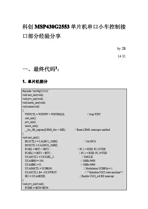
msp430G2553程序实例
- 格式:ppt
- 大小:3.20 MB
- 文档页数:49
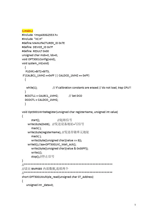
#include "msp430g2553.h"#include "UART.h"#include "N5110.h"#define TXRX_FIFO 1#define AddressUse 1#ifndef uchar#define uchar unsigned char#endif#ifndef uint#define uint unsigned int#endifuchar get_bug = 0;/****************************************************************延时***************************************************************/ void UART_delay(uint x){uint a, b;for(a=x; a>0; a--)for(b=110; b>0; b--);}/***************************************************************** *名称:UART_Set()*功能:UART串口设置*入口参数:baud: 波特率1200 2400 4800 9600(默认) 19200 38400 57600 * mctl: 波特率修整* data: 数据位,8:8位,7:7位,默认8位* jiouwei: 奇偶位,'n':无(默认),'o':奇校验,'e':偶校验* stop: 停止位,2:2位停止位,其他均为默认的1位* R_T: 收发模式,1:收;2:发;3:收发*出口参数:无*使用范例:UART_Set(9600,2,8,'n',1,3)*****************************************************************/ void UART_Set(uint baud,uchar mctl,uchar data,char jiouwei,uchar stop,uchar R_T) {UCA0CTL1 |=UCSWRST; //软件复位if(baud<=9600){UCA0CTL1 |= UCSSEL_1; //ACLK}{UCA0CTL1 |= UCSSEL_2; //SMCLK}switch(baud){case 1200: UCA0BR0 = 0X1B;//1200波特率//波特率计算UCA0BR1 = 0X6B; //波特率=BRCLK/N=(UBR+(M7+M6+M5+M4+M3+M2+M1+M0)/8)break; //例如:BRCLK=8MHz,要产生BITCLK=115200Hz,分频器的分频系数为8000 / 115.2 =69.44444444case 2400: UCA0BR0 = 0X0D;//2400波特率//所以设置分频器的计数值为69。
MSP430G2553捕获程序案例与经验分享MSP430G2553单片机定时器A有3个捕获比较寄存器CCR0,CCR1,CCR2.。
MSP430G2553捕获程序应用很广泛,电子工程师可以多加了解。
所谓捕获,就是我们来检测外围的信号跳变时刻(此时信号理解为数字信号,即脉冲),此信号乃为我们捕获的对象,可以测量信号的脉冲宽度,即频率等。
捕获首先需要考虑的初始化工作1.设置BCS模块,确定系统时钟MCLK子系统时钟SMCLK把MCLK设置为8MHZ,SMCLK设置为1MHZ。
2.捕获输入引脚的选择选择IO引脚时应查阅器件的手册,能够快速的查阅PDF资料找到正确的答案是一个程序员的基本素质。
3.程序设计思路根据测频的原理,需要2次捕获才能测量一次输入信号的频率。
因此要定义2个变量保存2次捕获结果。
变量是无符号的整数型变量(与捕获寄存器的字长匹配)。
输入信号与CPU的工作是异步的,所以设计程序的时候是不知道什么时候才有捕获输入。
程序处理何时发生了捕获的方法有2种一是查询的方法,定时器硬件在发生捕获事件后会置捕获中断表示CCIF为1,程序在主循环里不断的查询这个标志即可判断是否有捕获事件发生。
二是定时器中断法,当发生捕获事件时必产生定时器中断,在中断中读取捕获寄存器即可。
查询的方法不是好的程序设计方法,因为查询时要占用CPU,使得CPU不能再做其他任务。
中断的方法对初学者有一定的困难。
即中断程序如何与主程序通信(交换信息)。
理解中断及设计中断服务程序要困难一些。
捕获模式捕获外部输入的信号的上升沿或下降沿或上升沿下降沿都捕捉,当捕捉发生时,把TAR 的值装载到TACCRx中,同时也可以进入中断,执行相应的操作。
这样利用捕捉上升沿或。
基于msp430g2553的红外遥控小车解码控制程序//遥控小车最终程序#include#define CPU_F ((double)12000000)//数字控制震荡器1MHZ#define delay_us(x) __delay_cycles((long)(CPU_F*(double)x/12000000.0))//延时X微秒#define delay_ms(x) __delay_cycles((long)(CPU_F*(double)x/12000.0))//延时X毫秒char const redled[8]={0x07,0x00,0x01,0x02,0x03,0x04,0x05,0x06};//led测试版对应的八个灯unsigned char receive[2]={0x00,0x00};//数据码,数据反码unsigned char j=0,k=0,f=0,led=0;//中断次数,receive的元素,,找到按键地址数组的第f个元素int flag=1;//***************************主程序********************//void main(void){WDTCTL=WDTPW+WDTHOLD; //关闭看门狗BCSCTL1=CALBC1_1MHZ; //这两句的作用,基本时钟系统控制,数控震荡控制,将时钟校准1MHZDCOCTL=CALDCO_1MHZ;P1DIR|=BIT0+BIT6+BIT2+BIT3+BIT4;//P1端口的P1.0、P1.6设置为输出方向P2DIR|=0x0f; //P2的0,1,2,3设置为输出口P1OUT|=BIT0+BIT6; //P1.0、P1.6输出高电平,次单片机的VCC为3.56VP1IE|=0X02; //P1.1中断使能P1IES|=BIT1; //P1.1中断边沿选择,下降沿触发P1IFG=0; //清P1.1中断标志_BIS_SR(GIE); //开总中断while(1) //{if(receive[0]==0xa2){flag=1;}if(receive[0]==0xe2){flag=-1;}if(flag==1) //正转P1.0{P1OUT&=~BIT3;P1OUT&=~BIT4;switch(receive[0]){case 0x68:{P1OUT&=~BIT0;P1OUT&=~BIT2;break;} //0键case0x30:{{P1OUT|=BIT0;P1OUT|=BIT2;delay_ms(1);P1OUT&=~B IT0;P1OUT&=~BIT2;delay_m s(9);}break;}//1键case0x18:{{P1OUT|=BIT0;P1OUT|=BIT2;delay_ms(2);P1OUT&=~B IT0;P1OUT&=~BIT2;delay_m s(8);}break;}//2键case0x7a:{{P1OUT|=BIT0;P1OUT|=BIT2;delay_ms(3);P1OUT&=~B IT0;P1OUT&=~BIT2;delay_m s(7);}break;}//3键case0x10:{{P1OUT|=BIT0;P1OUT|=BIT2;delay_ms(4);P1OUT&=~BIT0;P1OUT&=~BIT2;delay_m s(6);}break;}//4键case0x38:{{P1OUT|=BIT0;P1OUT|=BIT2;delay_ms(5);P1OUT&=~B IT0;P1OUT&=~BIT2;delay_m s(5);}break;}//5键case0x5a:{{P1OUT|=BIT0;P1OUT|=BIT2;delay_ms(6);P1OUT&=~B IT0;P1OUT&=~BIT2;delay_m s(4);}break;}//6键case0x42:{{P1OUT|=BIT0;P1OUT|=BIT2;delay_ms(7);P1OUT&=~B IT0;P1OUT&=~BIT2;delay_m s(3);}break;}//7键case0x4a:{{P1OUT|=BIT0;P1OUT|=BIT2;delay_ms(8);P1OUT&=~B IT0;P1OUT&=~BIT2;delay_m s(2);}break;}//8键case 0x52:{P1OUT|=BIT0;P1OUT|=BIT2;break;} //9键}}else if(flag==-1) //反转P1.2{P1OUT&=~BIT0;P1OUT&=~BIT2;switch(receive[0]){case 0x68:{P1OUT&=~BIT3;P1OUT&=~BIT4;break;} //0键case0x30:{{P1OUT|=BIT3;P1OUT|=BIT4;delay_ms(1);P1OUT&=~B IT3;P1OUT&=~BIT4;delay_m s(9);}break;}//1键case0x18:{{P1OUT|=BIT3;P1OUT|=BIT4;delay_ms(2);P1OUT&=~B IT3;P1OUT&=~BIT4;delay_m s(8);}break;}//2键case0x7a:{{P1OUT|=BIT3;P1OUT|=BIT4;delay_ms(3);P1OUT&=~B IT3;P1OUT&=~BIT4;delay_m s(7);}break;}//3键case0x10:{{P1OUT|=BIT3;P1OUT|=BIT4;delay_ms(4);P1OUT&=~B IT3;P1OUT&=~BIT4;delay_m s(6);}break;}//4键case0x38:{{P1OUT|=BIT3;P1OUT|=BIT4;delay_ms(5);P1OUT&=~B IT3;P1OUT&=~BIT4;delay_m s(5);}break;}//5键case0x5a:{{P1OUT|=BIT3;P1OUT|=BIT4;delay_ms(6);P1OUT&=~B IT3;P1OUT&=~BIT4;delay_m s(4);}break;}//6键case0x42:{{P1OUT|=BIT3;P1OUT|=BIT4;delay_ms(7);P1OUT&=~B IT3;P1OUT&=~BIT4;delay_m s(3);}break;}//7键case0x4a:{{P1OUT|=BIT3;P1OUT|=BIT4;delay_ms(8);P1OUT&=~B IT3;P1OUT&=~BIT4;delay_m s(2);}break;}//8键case 0x52:{P1OUT|=BIT3;P1OUT|=BIT4;break;} //9键}}}}//*********************红外遥控器中断程序*******************//#pragma vector=PORT1_VECTOR //中断程序的格式:#pragma vector=中断矢量__interrupt void port1(void)//格式:__interrupt void 函数名(void){P1IFG=0X00; //清P1中断标志int count=0; //高电平持续时间计数值while(!(P1IN&BIT1)); //等电平变为高电平while(P1IN&BIT1) //计算高电平持续时间{count++;if(count>8000)return;//如果高电平持续时间过长则推出中断程序}if(j>16) //一体化红外接收头一接收遥控器信号,就会输出32位的脉冲序列波,其中后16位{ //决定遥控器的按键地址,16位由8位数据码和数据反码组成,我们需要将其解码//time[j-17]=count; //将记得的高电平持续时间放入时间数组中if(j==25)k++; //到数据反码的起始位的时候,我让receive数组元素下标+1receive[k]<<=1; //接收数据码左移一位,比如:xxxx xxxx 左移一位后xxxx xxx0if(count>80)receive[k]|=0x01;//高电平持续时间超过80,则将左移一位后的最低位变1,} //结果变为,xxxx xxx1,如果没超过80则保持不变,xxxx xxx0 j++;if(j>32){j=0;k=0; //解码结束,j,k值清零delay_ms(150);}}。
MSPG2553 例程1.//************************************************************************* *****// LaunchPad Lab2 - Software Toggle P1.0,//// MSP430G2xx2// -----------------// /|\| XIN|-// | | |// --|RST XOUT|-// | |// | P1.0|-->LED////************************************************************************* *****#include <msp430g2553.h>void main(void){WDTCTL = WDTPW + WDTHOLD; // Stop watchdog timerif (CALBC1_1MHZ == 0xFF || CALDCO_1MHZ == 0xFF){while(1); // If calibration constants erased, trap CPU!!}// Configure Basic ClockBCSCTL1 = CALBC1_1MHZ; // Set rangeDCOCTL = CALDCO_1MHZ; // Set DCO step + modulationBCSCTL3 |= LFXT1S_2; // Set LFXT1P1DIR = BIT6; // P1.6 output (green LED)P1OUT = 0; // LED offIFG1 &= ~OFIFG; // Clear OSCFault flagBCSCTL2 |=SELM_1 + DIVM_0; // Set MCLKfor(;;){P1OUT = BIT6; // P1.6 on (green LED)_delay_cycles(100);P1OUT = 0; // green LED off_delay_cycles(5000);}}2.//************************************************************************* *****// LaunchPad Lab3 - Software Port Interrupt Service//// MSP430G2xx2// -----------------// /|\| XIN|-// | | |// --|RST XOUT|-// /|\ | |// --o--|P1.3 P1.0|-->LED// \|/////************************************************************************* *****#include <msp430g2553.h>void main(void){WDTCTL = WDTPW + WDTHOLD; // Stop watchdog timerP1DIR |= BIT0; // Set P1.0 to output directionP1IES |= BIT3; // P1.3 Hi/lo edgeP1IFG &= ~BIT3; // P1.3 IFG clearedP1IE |= BIT3; // P1.3 interrupt enabled_BIS_SR(LPM4_bits + GIE); // Enter LPM4 w/interrupt }// Port 1 interrupt service routine#pragma vector=PORT1_VECTOR__interrupt void Port_1(void){if (P1IFG & BIT3){P1OUT ^= BIT0; // P1.0 = toggleP1IFG &= ~BIT3; // P1.3 IFG cleared }}3.//************************************************************************* *****// LaunchPad Lab5 - ADC10, Sample A10 Temp and Convert to oC and oF//// MSP430G2452// -----------------// /|\| XIN|-// | | |// --|RST XOUT|-// | |// |A10 |////************************************************************************* *****#include "msp430g2553.h"long temp;long IntDegF;long IntDegC;void main(void){WDTCTL = WDTPW + WDTHOLD; // Stop WDT//Configure ADC10ADC10CTL1 = INCH_10 + ADC10DIV_3; // Choose ADC Channel as Temp SensorADC10CTL0 = SREF_1 + ADC10SHT_3 + REFON + ADC10ON + ADC10IE;//Choose ADC Ref source__enable_interrupt(); // Enable interrupts.TACCR0 = 30; // Delay to allow Ref to settleTACCTL0 |= CCIE; // Compare-mode interrupt.TACTL = TASSEL_2 | MC_1; // TACLK = SMCLK, Up mode.LPM0; // Wait for delay.TACCTL0 &= ~CCIE; // Disable timer Interrupt__disable_interrupt();while(1){ADC10CTL0 |= ENC + ADC10SC; // Sampling and conversion start__bis_SR_register(LPM0_bits + GIE); // LPM0 with interrupts enabled// oF = ((A10/1024)*1500mV)-923mV)*1/1.97mV = A10*761/1024 - 468temp = ADC10MEM;IntDegF = ((temp - 630) * 761) / 1024;// oC = ((A10/1024)*1500mV)-986mV)*1/3.55mV = A10*423/1024 - 278temp = ADC10MEM;IntDegC = ((temp - 673) * 423) / 1024;__no_operation(); // SET BREAKPOINT HERE}}// ADC10 interrupt service routine#pragma vector=ADC10_VECTOR__interrupt void ADC10_ISR (void){__bic_SR_register_on_exit(LPM0_bits); // Clear CPUOFF bit from 0(SR)}#pragma vector=TIMER0_A0_VECTOR__interrupt void ta0_isr(void){TACTL = 0;__bic_SR_register_on_exit(LPM0_bits); // Clear CPUOFF bit from 0(SR)}4.//************************************************************************* *****// MSP430F20xx Demo - Basic Clock, Output Buffered SMCLK, ACLK and MCLK/10 //// Description: Buffer ACLK on P2.0, default SMCLK(DCO) on P1.4 and MCLK/10 on // P1.5.// ACLK = LFXT1 = VLO, MCLK = SMCLK = default DCO// //* External watch crystal installed on XIN XOUT is required for ACLK *////// MSP430F20xx// -----------------// /|\| XIN|-// | | |// --|RST XOUT|-// | |// | P1.4/SMCLK|-->SMCLK = Default DCO// | P1.5|-->MCLK/10 = DCO/10// | P1.0/ACLK|-->ACLK = VLO//// M. Buccini / L. Westlund// Texas Instruments Inc.// October 2005// Built with IAR Embedded Workbench Version: 3.40A//************************************************************************* *****#include <msp430x20x3.h>unsigned char s;void main(void){WDTCTL = WDTPW +WDTHOLD; // Stop Watchdog TimerBCSCTL3 |= LFXT1S_2; // LFXT1 = VLO//DCOCTL = 0;//BCSCTL1 = CALBC1_16MHZ;//DCOCTL = CALBC1_16MHZ;P1DIR |= 0x31; // P1.0,5 and P1.4 outputsP1SEL |= 0x11; // P1.0,4 ACLK/VLO, SMCLK/DCO output//SMCLK Sub-System Main Clk,ACLK和SMCLK可以通过复用引脚输出,MCLK 不能直接输出体现, MCLK可以配置为VLO或者DCOwhile(1){P1OUT |= 0x20; // P1.5 = 1, 通过开关P1.5来体现MCLK,这两条指令的周期大概为SMCLK的1/10P1OUT &= ~0x20;//20;}}5.//************************************************************************* *****// MSP430xG46x Demo - FLL+, Runs Internal DCO at 8MHz// Description: This program demonstrates setting the internal DCO to run at// 8MHz with auto-calibration by the FLL+.// ACLK = LFXT1 = 32768Hz, MCLK = SMCLK = DCO = (121+1) x 2 x ACLK = 7995392Hz// //* An external watch crystal between XIN & XOUT is required for ACLK *////// MSP430xG461x// -----------------// /|\| XIN|-// | | | 32kHz// --|RST XOUT|-// | |// | P1.1|--> MCLK = 8MHz// | |// | P1.5|--> ACLK = 32kHz// | |//// K. Quiring/ M. Mitchell// Texas Instruments Inc.// October 2006// Built with IAR Embedded Workbench Version: 3.41A//************************************************************************* ****#include <msp430xG46x.h>void main(void){WDTCTL = WDTPW + WDTHOLD; // Stop watchdog timerFLL_CTL0 |= DCOPLUS + XCAP18PF; // DCO+ set, freq = xtal x D x N+1 SCFI0 |= FN_4; // x2 DCO freq, 8MHz nominal DCOSCFQCTL = 121; // (121+1) x 32768 x 2 = 7.99 MHzP1DIR = 0x22; // P1.1 & P1.5 to output directionP1SEL = 0x22; // P1.1 & P1.5 to output MCLK & ACLKwhile(1); // Loop in place}6.//************************************************************************* ***// MSP430xG46x Demo - Flash In-System Programming, Copy SegA to SegB//// Description: This program first erases flash seg A, then it increments all// values in seg A, then it erases seg B, then copies seg A to seg B.// Assumed MCLK 550kHz - 900kHz.// //* Set Breakpoint on NOP in the Mainloop to avoid Stressing Flash *////// MSP430xG461x// -----------------// /|\| XIN|-// | | |// --|RST XOUT|-// | |//// M. Mitchell// Texas Instruments Inc.// Feb 2005// Built with IAR Embedded Workbench Version: 3.21A//************************************************************************* *****#include <msp430xG46x.h>char value; // 8-bit value to write to segment A// Function prototypesvoid write_SegA (char value);void copy_A2B (void);void main(void){WDTCTL = WDTPW + WDTHOLD; // Stop watchdog timerFCTL2 = FWKEY + FSSEL0 + FN0; // MCLK/2 for Flash Timing Generatorvalue = 0; // Initialize valuewhile(1) // Repeat forever{write_SegA(value++); // Write segment A, increment valuecopy_A2B(); // Copy segment A to B_NOP(); // SET BREAKPOINT HERE}}void write_SegA (char value){char *Flash_ptr; // Flash pointerunsigned int i;Flash_ptr = (char *) 0x1080; // Initialize Flash pointerFCTL1 = FWKEY + ERASE; // Set Erase bitFCTL3 = FWKEY; // Clear Lock bit*Flash_ptr = 0; // Dummy write to erase Flash segmentFCTL1 = FWKEY + WRT; // Set WRT bit for write operationfor (i=0; i<128; i++){*Flash_ptr++ = value; // Write value to flash}FCTL1 = FWKEY; // Clear WRT bitFCTL3 = FWKEY + LOCK; // Set LOCK bit}void copy_A2B (void){char *Flash_ptrA; // Segment A pointerchar *Flash_ptrB; // Segment B pointerunsigned int i;Flash_ptrA = (char *) 0x1080; // Initialize Flash segment A pointerFlash_ptrB = (char *) 0x1000; // Initialize Flash segment B pointerFCTL1 = FWKEY + ERASE; // Set Erase bitFCTL3 = FWKEY; // Clear Lock bit*Flash_ptrB = 0; // Dummy write to erase Flash segment B FCTL1 = FWKEY + WRT; // Set WRT bit for write operationfor (i=0; i<128; i++){*Flash_ptrB++ = *Flash_ptrA++; // Copy value segment A to segment B}FCTL1 = FWKEY; // Clear WRT bitFCTL3 = FWKEY + LOCK; // Set LOCK bit}7.//************************************************************************* *****// MSP430xG46x Demo - Software Port Interrupt on P1.0 from LPM4//// Description: A hi/low transition on P1.0 will trigger P1_ISR which,// toggles P2.1. Normal mode is LPM4 ~ 0.1uA. LPM4 current can be measured// with the LED removed, all unused P1.x/P2.x configured as output or inputs// pulled high or low, and ensure the P2.0 interrupt input does not float.// ACLK = 32.768kHz, MCLK = SMCLK = default DCO//// MSP430xG461x// -----------------// /|\| |// | | |// --|RST |// /|\ | |// --o--|P1.0 P2.1|-->LED// \|///// K. Quiring/ M. Mitchell// Texas Instruments Inc.// October 2006// Built with IAR Embedded Workbench Version: 3.41A//************************************************************************* *****#include <msp430xG46x.h>void main(void){WDTCTL = WDTPW + WDTHOLD; // Stop WDTFLL_CTL0 |= XCAP14PF; // Configure load capsP2DIR = BIT1; // Set P2.1 to output directionP1IES = BIT0; // H-L transitionP1IE = BIT0; // Enable interrupt_BIS_SR(LPM4_bits + GIE); // LPM4, enable interrupts}// Port 1 interrupt service routine#pragma vector=PORT1_VECTOR__interrupt void Port1_ISR (void){unsigned volatile int i;for (i=10000; i>0; i--); // Debounce delayP1IFG &= ~BIT0; // Clear P1IFGif ((P1IN & 0x01) == 0)P2OUT ^= 0x02; // Toggle P2.1 using exclusive-OR}8.//************************************************************************* *****// MSP430xG46x Demo - Software Port Interrupt on P1.0 from LPM4//// Description: A hi/low transition on P1.0 will trigger P1_ISR which,// toggles P2.1. Normal mode is LPM4 ~ 0.1uA. LPM4 current can be measured// with the LED removed, all unused P1.x/P2.x configured as output or inputs// pulled high or low, and ensure the P2.0 interrupt input does not float.// ACLK = 32.768kHz, MCLK = SMCLK = default DCO//// MSP430xG461x// -----------------// /|\| |// | | |// --|RST |// /|\ | |// --o--|P1.0 P2.1|-->LED// \|///// K. Quiring/ M. Mitchell// Texas Instruments Inc.// October 2006// Built with IAR Embedded Workbench Version: 3.41A//************************************************************************* *****#include <msp430xG46x.h>void main(void){WDTCTL = WDTPW + WDTHOLD; // Stop WDTFLL_CTL0 |= XCAP14PF; // Configure load capsP2DIR = BIT1; // Set P2.1 to output directionP1IES = BIT0; // H-L transitionP1IE = BIT0; // Enable interrupt_BIS_SR(LPM4_bits + GIE); // LPM4, enable interrupts}// Port 1 interrupt service routine#pragma vector=PORT1_VECTOR__interrupt void Port1_ISR (void){unsigned volatile int i;for (i=10000; i>0; i--); // Debounce delayP1IFG &= ~BIT0; // Clear P1IFGif ((P1IN & 0x01) == 0)P2OUT ^= 0x02; // Toggle P2.1 using exclusive-OR}9.//************************************************************************* *****// MSP430xG46x Demo - USCI_A0, 115200 UART Echo ISR, DCO SMCLK// (modified code example "msp430xG46x_uscia0_uart_01_115k.c")//// Description: Echo a received character, RX ISR used. Normal mode is LPM0.// USCI_A0 RX interrupt triggers TX Echo.// Baud rate divider with 1048576hz = 1048576/115200 = ~9.1 (009h|01h)// ACLK = LFXT1 = 32768Hz, MCLK = SMCLK = default DCO = 32 x ACLK = 1048576Hz// //* An external watch crystal between XIN & XOUT is required for ACLK *////// MSP430FG4619// -----------------// /|\| XIN|-// | | | 32kHz// --|RST XOUT|-// | |// | P2.5/UCA0RXD|<------------// | | 115200 - 8N1// | P2.4/UCA0TXD|------------>//// Texas Instruments Inc.// October 2006// Built with IAR Embedded Workbench Version: 3.41A//************************************************************************* *****#include "msp430xG46x.h"void main(void){volatile unsigned int i;WDTCTL = WDTPW+WDTHOLD; // Stop WDTFLL_CTL0 |= XCAP14PF; // Configure load capsdo{IFG1 &= ~OFIFG; // Clear OSCFault flagfor (i = 0x47FF; i > 0; i--); // Time for flag to set}while ((IFG1 & OFIFG)); // OSCFault flag still set?P2SEL |= 0x030; // P2.4,5 = USCI_A0 RXD/TXDUCA0CTL1 |= UCSSEL_2; // SMCLKUCA0BR0 = 18;0x09; // 1MHz 115200UCA0BR1 = 0;0x00; // 1MHz 115200UCA0MCTL = 0;0x02; // ModulationUCA0CTL1 &= ~UCSWRST; // **Initialize USCI state machine**IE2 |= UCA0RXIE; // Enable USCI_A0 RX interrupt_BIS_SR(LPM0_bits + GIE); // Enter LPM0, interrupts enabled}// Echo back RXed character, confirm TX buffer is ready first#pragma vector=USCIAB0RX_VECTOR__interrupt void USCIA0RX_ISR (void){while(!(IFG2&UCA0TXIFG));UCA0TXBUF = UCA0RXBUF; // TX -> RXed character}10./************************************************************************** ***** MSP-EXP430G2-LaunchPad User Experience Application** 1. Device starts up in LPM3 + blinking LED to indicate device is alive* + Upon first button press, device transitions to application mode* 2. Application Mode* + Continuously sample ADC Temp Sensor channel, compare result against* initial value* + Set PWM based on measured ADC offset: Red LED for positive offset, Green* LED for negative offset* + Transmit temperature value via TimerA UART to PC* + Button Press --> Calibrate using current temperature* Send character '� via UART, notifying PC******************************************************************************/ #include "msp430g2553.h"#define LED0 BIT0#define LED1 BIT6#define LED_DIR P1DIR#define LED_OUT P1OUT#define BUTTON BIT3#define BUTTON_OUT P1OUT#define BUTTON_DIR P1DIR#define BUTTON_IN P1IN#define BUTTON_IE P1IE#define BUTTON_IES P1IES#define BUTTON_IFG P1IFG#define BUTTON_REN P1REN#define TXD BIT1 // TXD on P1.1 #define RXD BIT2 // RXD on P1.2#define APP_STANDBY_MODE 0#define APP_APPLICATION_MODE 1#define TIMER_PWM_MODE 0#define TIMER_UART_MODE 1#define TIMER_PWM_PERIOD 2000#define TIMER_PWM_OFFSET 20#define TEMP_SAME 0#define TEMP_HOT 1#define TEMP_COLD 2#define TEMP_THRESHOLD 5// Conditions for 9600/4=2400 Baud SW UART, SMCLK = 1MHz#define Bitime_5 0x05*4 // ~ 0.5 bit length + small adjustment#define Bitime 13*4//0x0D#define UART_UPDA TE_INTERV AL 1000unsigned char BitCnt;unsigned char applicationMode = APP_STANDBY_MODE;unsigned char timerMode = TIMER_PWM_MODE;unsigned char tempMode;unsigned char calibrateUpdate = 0;unsigned char tempPolarity = TEMP_SAME;unsigned int TXByte;/* Using an 8-value moving average filter on sampled ADC values */long tempMeasured[8];unsigned char tempMeasuredPosition=0;long tempAverage;long tempCalibrated, tempDifference;void InitializeLeds(void);void InitializeButton(void);void PreApplicationMode(void); // Blinks LED, waits for button pressvoid ConfigureAdcTempSensor(void);void ConfigureTimerPwm(void);void ConfigureTimerUart(void);void Transmit(void);void InitializeClocks(void);void main(void){unsigned int uartUpdateTimer = UART_UPDATE_INTERV AL;unsigned char i;WDTCTL = WDTPW + WDTHOLD; // Stop WDTInitializeClocks();InitializeButton();InitializeLeds();PreApplicationMode(); // Blinks LEDs, waits for button press/* Application Mode begins */applicationMode = APP_APPLICATION_MODE;ConfigureAdcTempSensor();ConfigureTimerPwm();__enable_interrupt(); // Enable interrupts./* Main Application Loop */while(1){ADC10CTL0 |= ENC + ADC10SC; // Sampling and conversion start__bis_SR_register(CPUOFF + GIE); // LPM0 with interrupts enabled/* Moving average filter out of 8 values to somewhat stabilize sampled ADC */tempMeasured[tempMeasuredPosition++] = ADC10MEM;if (tempMeasuredPosition == 8)tempMeasuredPosition = 0;tempAverage = 0;for (i = 0; i < 8; i++)tempAverage += tempMeasured[i];tempAverage >>= 3; // Divide by 8 to get averageif ((--uartUpdateTimer == 0) || calibrateUpdate ){ConfigureTimerUart();if (calibrateUpdate){TXByte = 248; // A character with high value, outside of temp rangeTransmit();calibrateUpdate = 0;TXByte = (unsigned char)( ((tempAverage - 630) * 761) / 1024 );Transmit();uartUpdateTimer = UART_UPDATE_INTERV AL;ConfigureTimerPwm();}tempDifference = tempAverage - tempCalibrated;if (tempDifference < -TEMP_THRESHOLD){tempDifference = -tempDifference;tempPolarity = TEMP_COLD;LED_OUT &= ~ LED1;}elseif (tempDifference > TEMP_THRESHOLD){tempPolarity = TEMP_HOT;LED_OUT &= ~ LED0;}else{tempPolarity = TEMP_SAME;TACCTL0 &= ~CCIE;TACCTL1 &= ~CCIE;LED_OUT &= ~(LED0 + LED1);}if (tempPolarity != TEMP_SAME){tempDifference <<= 3;tempDifference += TIMER_PWM_OFFSET;TACCR1 = ( (tempDifference) < (TIMER_PWM_PERIOD-1) ? (tempDifference) : (TIMER_PWM_PERIOD-1) );TACCTL0 |= CCIE;TACCTL1 |= CCIE;}}void PreApplicationMode(void){LED_DIR |= LED0 + LED1;LED_OUT |= LED0; // To enable the LED toggling effect LED_OUT &= ~LED1;BCSCTL1 |= DIV A_1; // ACLK/2BCSCTL3 |= LFXT1S_2; // ACLK = VLOTACCR0 = 1200; //TACTL = TASSEL_1 | MC_1; // TACLK = SMCLK, Up mode. TACCTL1 = CCIE + OUTMOD_3; // TACCTL1 Capture Compare TACCR1 = 600;__bis_SR_register(LPM3_bits + GIE); // LPM0 with interrupts enabled}void ConfigureAdcTempSensor(void){unsigned char i;/* Configure ADC Temp Sensor Channel */ADC10CTL1 = INCH_10 + ADC10DIV_3; // Temp Sensor ADC10CLK/4 ADC10CTL0 = SREF_1 + ADC10SHT_3 + REFON + ADC10ON + ADC10IE;__delay_cycles(1000); // Wait for ADC Ref to settleADC10CTL0 |= ENC + ADC10SC; // Sampling and conversion start __bis_SR_register(CPUOFF + GIE); // LPM0 with interrupts enabled tempCalibrated = ADC10MEM;for (i=0; i < 8; i++)tempMeasured[i] = tempCalibrated;tempAverage = tempCalibrated;}void ConfigureTimerPwm(void){timerMode = TIMER_PWM_MODE;TACCR0 = TIMER_PWM_PERIOD; //TACTL = TASSEL_2 | MC_1; // TACLK = SMCLK, Up mode. TACCTL0 = CCIE;TACCTL1 = CCIE + OUTMOD_3; // TACCTL1 Capture Compare TACCR1 = 1;}void ConfigureTimerUart(void){timerMode = TIMER_UART_MODE; // Configure TimerA0 UART TXCCTL0 = OUT; // TXD Idle as MarkTACTL = TASSEL_2 + MC_2 + ID_3; // SMCLK/8, continuous modeP1SEL |= TXD + RXD; //P1DIR |= TXD; //}// Function Transmits Character from TXBytevoid Transmit(){BitCnt = 0xA; // Load Bit counter, 8data + ST/SP while (CCR0 != TAR) // Prevent async captureCCR0 = TAR; // Current state of TA counterCCR0 += Bitime; // Some time till first bitTXByte |= 0x100; // Add mark stop bit to TXByteTXByte = TXByte << 1; // Add space start bitCCTL0 = CCIS0 + OUTMOD0 + CCIE; // TXD = mark = idlewhile ( CCTL0 & CCIE ); // Wait for TX completion}// Timer A0 interrupt service routine#pragma vector=TIMER0_A0_VECTOR__interrupt void Timer_A (void){if (timerMode == TIMER_UART_MODE){CCR0 += Bitime; // Add Offset to CCR0if (CCTL0 & CCIS0) // TX on CCI0B?{if ( BitCnt == 0)CCTL0 &= ~ CCIE; // All bits TXed, disable interrupt else{CCTL0 |= OUTMOD2; // TX Spaceif (TXByte & 0x01)CCTL0 &= ~ OUTMOD2; // TX MarkTXByte = TXByte >> 1;BitCnt --;}}}else{if (tempPolarity == TEMP_HOT)LED_OUT |= LED1;if (tempPolarity == TEMP_COLD)LED_OUT |= LED0;TACCTL0 &= ~CCIFG;}}#pragma vector=TIMER0_A1_VECTOR__interrupt void ta1_isr(void){TACCTL1 &= ~CCIFG;if (applicationMode == APP_APPLICATION_MODE)LED_OUT &= ~(LED0 + LED1);elseLED_OUT ^= (LED0 + LED1);}void InitializeClocks(void){BCSCTL1 = CALBC1_1MHZ; // Set rangeDCOCTL = CALDCO_1MHZ;BCSCTL2 &= ~(DIVS_3); // SMCLK = DCO / 8 = 1MHz }void InitializeButton(void) // Configure Push Button{BUTTON_DIR &= ~BUTTON;BUTTON_OUT |= BUTTON;BUTTON_REN |= BUTTON;BUTTON_IES |= BUTTON;BUTTON_IFG &= ~BUTTON;BUTTON_IE |= BUTTON;}void InitializeLeds(void){LED_DIR |= LED0 + LED1;LED_OUT &= ~(LED0 + LED1);}/* ************************************************************** Port Interrupt for Button Press* 1. During standby mode: to exit and enter application mode* 2. During application mode: to recalibrate temp sensor* *********************************************************** */#pragma vector=PORT1_VECTOR__interrupt void PORT1_ISR(void){BUTTON_IFG = 0;BUTTON_IE &= ~BUTTON; /* Debounce */WDTCTL = WDT_ADL Y_250;IFG1 &= ~WDTIFG; /* clear interrupt flag */IE1 |= WDTIE;if (applicationMode == APP_APPLICATION_MODE){tempCalibrated = tempAverage;calibrateUpdate = 1;}else{applicationMode = APP_APPLICATION_MODE; // Switch from STANDBY to APPLICATION MODE__bic_SR_register_on_exit(LPM3_bits);}}#pragma vector=WDT_VECTOR__interrupt void WDT_ISR(void){IE1 &= ~WDTIE; /* disable interrupt */IFG1 &= ~WDTIFG; /* clear interrupt flag */WDTCTL = WDTPW + WDTHOLD; /* put WDT back in hold state */BUTTON_IE |= BUTTON; /* Debouncing complete */ }// ADC10 interrupt service routine#pragma vector=ADC10_VECTOR__interrupt void ADC10_ISR (void){__bic_SR_register_on_exit(CPUOFF); // Return to active mode}。


MSPG2553 例程1.//************************************************************************* *****// LaunchPad Lab2 - Software Toggle P1.0,//// MSP430G2xx2// -----------------// /|\| XIN|-// | | |// --|RST XOUT|-// | |// | P1.0|-->LED////************************************************************************* *****#include <msp430g2553.h>void main(void){WDTCTL = WDTPW + WDTHOLD; // Stop watchdog timerif (CALBC1_1MHZ == 0xFF || CALDCO_1MHZ == 0xFF){while(1); // If calibration constants erased, trap CPU!!}// Configure Basic ClockBCSCTL1 = CALBC1_1MHZ; // Set rangeDCOCTL = CALDCO_1MHZ; // Set DCO step + modulationBCSCTL3 |= LFXT1S_2; // Set LFXT1P1DIR = BIT6; // P1.6 output (green LED)P1OUT = 0; // LED offIFG1 &= ~OFIFG; // Clear OSCFault flagBCSCTL2 |=SELM_1 + DIVM_0; // Set MCLKfor(;;){P1OUT = BIT6; // P1.6 on (green LED)_delay_cycles(100);P1OUT = 0; // green LED off_delay_cycles(5000);}}2.//************************************************************************* *****// LaunchPad Lab3 - Software Port Interrupt Service//// MSP430G2xx2// -----------------// /|\| XIN|-// | | |// --|RST XOUT|-// /|\ | |// --o--|P1.3 P1.0|-->LED// \|/////************************************************************************* *****#include <msp430g2553.h>void main(void){WDTCTL = WDTPW + WDTHOLD; // Stop watchdog timerP1DIR |= BIT0; // Set P1.0 to output directionP1IES |= BIT3; // P1.3 Hi/lo edgeP1IFG &= ~BIT3; // P1.3 IFG clearedP1IE |= BIT3; // P1.3 interrupt enabled_BIS_SR(LPM4_bits + GIE); // Enter LPM4 w/interrupt }// Port 1 interrupt service routine#pragma vector=PORT1_VECTOR__interrupt void Port_1(void){if (P1IFG & BIT3){P1OUT ^= BIT0; // P1.0 = toggleP1IFG &= ~BIT3; // P1.3 IFG cleared }}3.//************************************************************************* *****// LaunchPad Lab5 - ADC10, Sample A10 Temp and Convert to oC and oF//// MSP430G2452// -----------------// /|\| XIN|-// | | |// --|RST XOUT|-// | |// |A10 |////************************************************************************* *****#include "msp430g2553.h"long temp;long IntDegF;long IntDegC;void main(void){WDTCTL = WDTPW + WDTHOLD; // Stop WDT//Configure ADC10ADC10CTL1 = INCH_10 + ADC10DIV_3; // Choose ADC Channel as Temp SensorADC10CTL0 = SREF_1 + ADC10SHT_3 + REFON + ADC10ON + ADC10IE;//Choose ADC Ref source__enable_interrupt(); // Enable interrupts.TACCR0 = 30; // Delay to allow Ref to settleTACCTL0 |= CCIE; // Compare-mode interrupt.TACTL = TASSEL_2 | MC_1; // TACLK = SMCLK, Up mode.LPM0; // Wait for delay.TACCTL0 &= ~CCIE; // Disable timer Interrupt__disable_interrupt();while(1){ADC10CTL0 |= ENC + ADC10SC; // Sampling and conversion start__bis_SR_register(LPM0_bits + GIE); // LPM0 with interrupts enabled// oF = ((A10/1024)*1500mV)-923mV)*1/1.97mV = A10*761/1024 - 468temp = ADC10MEM;IntDegF = ((temp - 630) * 761) / 1024;// oC = ((A10/1024)*1500mV)-986mV)*1/3.55mV = A10*423/1024 - 278temp = ADC10MEM;IntDegC = ((temp - 673) * 423) / 1024;__no_operation(); // SET BREAKPOINT HERE}}// ADC10 interrupt service routine#pragma vector=ADC10_VECTOR__interrupt void ADC10_ISR (void){__bic_SR_register_on_exit(LPM0_bits); // Clear CPUOFF bit from 0(SR)}#pragma vector=TIMER0_A0_VECTOR__interrupt void ta0_isr(void){TACTL = 0;__bic_SR_register_on_exit(LPM0_bits); // Clear CPUOFF bit from 0(SR)}4.//************************************************************************* *****// MSP430F20xx Demo - Basic Clock, Output Buffered SMCLK, ACLK and MCLK/10 //// Description: Buffer ACLK on P2.0, default SMCLK(DCO) on P1.4 and MCLK/10 on // P1.5.// ACLK = LFXT1 = VLO, MCLK = SMCLK = default DCO// //* External watch crystal installed on XIN XOUT is required for ACLK *////// MSP430F20xx// -----------------// /|\| XIN|-// | | |// --|RST XOUT|-// | |// | P1.4/SMCLK|-->SMCLK = Default DCO// | P1.5|-->MCLK/10 = DCO/10// | P1.0/ACLK|-->ACLK = VLO//// M. Buccini / L. Westlund// Texas Instruments Inc.// October 2005// Built with IAR Embedded Workbench Version: 3.40A//************************************************************************* *****#include <msp430x20x3.h>unsigned char s;void main(void){WDTCTL = WDTPW +WDTHOLD; // Stop Watchdog TimerBCSCTL3 |= LFXT1S_2; // LFXT1 = VLO//DCOCTL = 0;//BCSCTL1 = CALBC1_16MHZ;//DCOCTL = CALBC1_16MHZ;P1DIR |= 0x31; // P1.0,5 and P1.4 outputsP1SEL |= 0x11; // P1.0,4 ACLK/VLO, SMCLK/DCO output//SMCLK Sub-System Main Clk,ACLK和SMCLK可以通过复用引脚输出,MCLK 不能直接输出体现, MCLK可以配置为VLO或者DCOwhile(1){P1OUT |= 0x20; // P1.5 = 1, 通过开关P1.5来体现MCLK,这两条指令的周期大概为SMCLK的1/10P1OUT &= ~0x20;//20;}}5.//************************************************************************* *****// MSP430xG46x Demo - FLL+, Runs Internal DCO at 8MHz// Description: This program demonstrates setting the internal DCO to run at// 8MHz with auto-calibration by the FLL+.// ACLK = LFXT1 = 32768Hz, MCLK = SMCLK = DCO = (121+1) x 2 x ACLK = 7995392Hz// //* An external watch crystal between XIN & XOUT is required for ACLK *////// MSP430xG461x// -----------------// /|\| XIN|-// | | | 32kHz// --|RST XOUT|-// | |// | P1.1|--> MCLK = 8MHz// | |// | P1.5|--> ACLK = 32kHz// | |//// K. Quiring/ M. Mitchell// Texas Instruments Inc.// October 2006// Built with IAR Embedded Workbench Version: 3.41A//************************************************************************* ****#include <msp430xG46x.h>void main(void){WDTCTL = WDTPW + WDTHOLD; // Stop watchdog timerFLL_CTL0 |= DCOPLUS + XCAP18PF; // DCO+ set, freq = xtal x D x N+1 SCFI0 |= FN_4; // x2 DCO freq, 8MHz nominal DCOSCFQCTL = 121; // (121+1) x 32768 x 2 = 7.99 MHzP1DIR = 0x22; // P1.1 & P1.5 to output directionP1SEL = 0x22; // P1.1 & P1.5 to output MCLK & ACLKwhile(1); // Loop in place}6.//************************************************************************* ***// MSP430xG46x Demo - Flash In-System Programming, Copy SegA to SegB//// Description: This program first erases flash seg A, then it increments all// values in seg A, then it erases seg B, then copies seg A to seg B.// Assumed MCLK 550kHz - 900kHz.// //* Set Breakpoint on NOP in the Mainloop to avoid Stressing Flash *////// MSP430xG461x// -----------------// /|\| XIN|-// | | |// --|RST XOUT|-// | |//// M. Mitchell// Texas Instruments Inc.// Feb 2005// Built with IAR Embedded Workbench Version: 3.21A//************************************************************************* *****#include <msp430xG46x.h>char value; // 8-bit value to write to segment A// Function prototypesvoid write_SegA (char value);void copy_A2B (void);void main(void){WDTCTL = WDTPW + WDTHOLD; // Stop watchdog timerFCTL2 = FWKEY + FSSEL0 + FN0; // MCLK/2 for Flash Timing Generatorvalue = 0; // Initialize valuewhile(1) // Repeat forever{write_SegA(value++); // Write segment A, increment valuecopy_A2B(); // Copy segment A to B_NOP(); // SET BREAKPOINT HERE}}void write_SegA (char value){char *Flash_ptr; // Flash pointerunsigned int i;Flash_ptr = (char *) 0x1080; // Initialize Flash pointerFCTL1 = FWKEY + ERASE; // Set Erase bitFCTL3 = FWKEY; // Clear Lock bit*Flash_ptr = 0; // Dummy write to erase Flash segmentFCTL1 = FWKEY + WRT; // Set WRT bit for write operationfor (i=0; i<128; i++){*Flash_ptr++ = value; // Write value to flash}FCTL1 = FWKEY; // Clear WRT bitFCTL3 = FWKEY + LOCK; // Set LOCK bit}void copy_A2B (void){char *Flash_ptrA; // Segment A pointerchar *Flash_ptrB; // Segment B pointerunsigned int i;Flash_ptrA = (char *) 0x1080; // Initialize Flash segment A pointerFlash_ptrB = (char *) 0x1000; // Initialize Flash segment B pointerFCTL1 = FWKEY + ERASE; // Set Erase bitFCTL3 = FWKEY; // Clear Lock bit*Flash_ptrB = 0; // Dummy write to erase Flash segment B FCTL1 = FWKEY + WRT; // Set WRT bit for write operationfor (i=0; i<128; i++){*Flash_ptrB++ = *Flash_ptrA++; // Copy value segment A to segment B}FCTL1 = FWKEY; // Clear WRT bitFCTL3 = FWKEY + LOCK; // Set LOCK bit}7.//************************************************************************* *****// MSP430xG46x Demo - Software Port Interrupt on P1.0 from LPM4//// Description: A hi/low transition on P1.0 will trigger P1_ISR which,// toggles P2.1. Normal mode is LPM4 ~ 0.1uA. LPM4 current can be measured// with the LED removed, all unused P1.x/P2.x configured as output or inputs// pulled high or low, and ensure the P2.0 interrupt input does not float.// ACLK = 32.768kHz, MCLK = SMCLK = default DCO//// MSP430xG461x// -----------------// /|\| |// | | |// --|RST |// /|\ | |// --o--|P1.0 P2.1|-->LED// \|///// K. Quiring/ M. Mitchell// Texas Instruments Inc.// October 2006// Built with IAR Embedded Workbench Version: 3.41A//************************************************************************* *****#include <msp430xG46x.h>void main(void){WDTCTL = WDTPW + WDTHOLD; // Stop WDTFLL_CTL0 |= XCAP14PF; // Configure load capsP2DIR = BIT1; // Set P2.1 to output directionP1IES = BIT0; // H-L transitionP1IE = BIT0; // Enable interrupt_BIS_SR(LPM4_bits + GIE); // LPM4, enable interrupts}// Port 1 interrupt service routine#pragma vector=PORT1_VECTOR__interrupt void Port1_ISR (void){unsigned volatile int i;for (i=10000; i>0; i--); // Debounce delayP1IFG &= ~BIT0; // Clear P1IFGif ((P1IN & 0x01) == 0)P2OUT ^= 0x02; // Toggle P2.1 using exclusive-OR}8.//************************************************************************* *****// MSP430xG46x Demo - Software Port Interrupt on P1.0 from LPM4//// Description: A hi/low transition on P1.0 will trigger P1_ISR which,// toggles P2.1. Normal mode is LPM4 ~ 0.1uA. LPM4 current can be measured// with the LED removed, all unused P1.x/P2.x configured as output or inputs// pulled high or low, and ensure the P2.0 interrupt input does not float.// ACLK = 32.768kHz, MCLK = SMCLK = default DCO//// MSP430xG461x// -----------------// /|\| |// | | |// --|RST |// /|\ | |// --o--|P1.0 P2.1|-->LED// \|///// K. Quiring/ M. Mitchell// Texas Instruments Inc.// October 2006// Built with IAR Embedded Workbench Version: 3.41A//************************************************************************* *****#include <msp430xG46x.h>void main(void){WDTCTL = WDTPW + WDTHOLD; // Stop WDTFLL_CTL0 |= XCAP14PF; // Configure load capsP2DIR = BIT1; // Set P2.1 to output directionP1IES = BIT0; // H-L transitionP1IE = BIT0; // Enable interrupt_BIS_SR(LPM4_bits + GIE); // LPM4, enable interrupts}// Port 1 interrupt service routine#pragma vector=PORT1_VECTOR__interrupt void Port1_ISR (void){unsigned volatile int i;for (i=10000; i>0; i--); // Debounce delayP1IFG &= ~BIT0; // Clear P1IFGif ((P1IN & 0x01) == 0)P2OUT ^= 0x02; // Toggle P2.1 using exclusive-OR}9.//************************************************************************* *****// MSP430xG46x Demo - USCI_A0, 115200 UART Echo ISR, DCO SMCLK// (modified code example "msp430xG46x_uscia0_uart_01_115k.c")//// Description: Echo a received character, RX ISR used. Normal mode is LPM0.// USCI_A0 RX interrupt triggers TX Echo.// Baud rate divider with 1048576hz = 1048576/115200 = ~9.1 (009h|01h)// ACLK = LFXT1 = 32768Hz, MCLK = SMCLK = default DCO = 32 x ACLK = 1048576Hz// //* An external watch crystal between XIN & XOUT is required for ACLK *////// MSP430FG4619// -----------------// /|\| XIN|-// | | | 32kHz// --|RST XOUT|-// | |// | P2.5/UCA0RXD|<------------// | | 115200 - 8N1// | P2.4/UCA0TXD|------------>//// Texas Instruments Inc.// October 2006// Built with IAR Embedded Workbench Version: 3.41A//************************************************************************* *****#include "msp430xG46x.h"void main(void){volatile unsigned int i;WDTCTL = WDTPW+WDTHOLD; // Stop WDTFLL_CTL0 |= XCAP14PF; // Configure load capsdo{IFG1 &= ~OFIFG; // Clear OSCFault flagfor (i = 0x47FF; i > 0; i--); // Time for flag to set}while ((IFG1 & OFIFG)); // OSCFault flag still set?P2SEL |= 0x030; // P2.4,5 = USCI_A0 RXD/TXDUCA0CTL1 |= UCSSEL_2; // SMCLKUCA0BR0 = 18;0x09; // 1MHz 115200UCA0BR1 = 0;0x00; // 1MHz 115200UCA0MCTL = 0;0x02; // ModulationUCA0CTL1 &= ~UCSWRST; // **Initialize USCI state machine**IE2 |= UCA0RXIE; // Enable USCI_A0 RX interrupt_BIS_SR(LPM0_bits + GIE); // Enter LPM0, interrupts enabled}// Echo back RXed character, confirm TX buffer is ready first#pragma vector=USCIAB0RX_VECTOR__interrupt void USCIA0RX_ISR (void){while(!(IFG2&UCA0TXIFG));UCA0TXBUF = UCA0RXBUF; // TX -> RXed character}10./************************************************************************** ***** MSP-EXP430G2-LaunchPad User Experience Application** 1. Device starts up in LPM3 + blinking LED to indicate device is alive* + Upon first button press, device transitions to application mode* 2. Application Mode* + Continuously sample ADC Temp Sensor channel, compare result against* initial value* + Set PWM based on measured ADC offset: Red LED for positive offset, Green* LED for negative offset* + Transmit temperature value via TimerA UART to PC* + Button Press --> Calibrate using current temperature* Send character '� via UART, notifying PC******************************************************************************/ #include "msp430g2553.h"#define LED0 BIT0#define LED1 BIT6#define LED_DIR P1DIR#define LED_OUT P1OUT#define BUTTON BIT3#define BUTTON_OUT P1OUT#define BUTTON_DIR P1DIR#define BUTTON_IN P1IN#define BUTTON_IE P1IE#define BUTTON_IES P1IES#define BUTTON_IFG P1IFG#define BUTTON_REN P1REN#define TXD BIT1 // TXD on P1.1 #define RXD BIT2 // RXD on P1.2#define APP_STANDBY_MODE 0#define APP_APPLICATION_MODE 1#define TIMER_PWM_MODE 0#define TIMER_UART_MODE 1#define TIMER_PWM_PERIOD 2000#define TIMER_PWM_OFFSET 20#define TEMP_SAME 0#define TEMP_HOT 1#define TEMP_COLD 2#define TEMP_THRESHOLD 5// Conditions for 9600/4=2400 Baud SW UART, SMCLK = 1MHz#define Bitime_5 0x05*4 // ~ 0.5 bit length + small adjustment#define Bitime 13*4//0x0D#define UART_UPDA TE_INTERV AL 1000unsigned char BitCnt;unsigned char applicationMode = APP_STANDBY_MODE;unsigned char timerMode = TIMER_PWM_MODE;unsigned char tempMode;unsigned char calibrateUpdate = 0;unsigned char tempPolarity = TEMP_SAME;unsigned int TXByte;/* Using an 8-value moving average filter on sampled ADC values */long tempMeasured[8];unsigned char tempMeasuredPosition=0;long tempAverage;long tempCalibrated, tempDifference;void InitializeLeds(void);void InitializeButton(void);void PreApplicationMode(void); // Blinks LED, waits for button pressvoid ConfigureAdcTempSensor(void);void ConfigureTimerPwm(void);void ConfigureTimerUart(void);void Transmit(void);void InitializeClocks(void);void main(void){unsigned int uartUpdateTimer = UART_UPDATE_INTERV AL;unsigned char i;WDTCTL = WDTPW + WDTHOLD; // Stop WDTInitializeClocks();InitializeButton();InitializeLeds();PreApplicationMode(); // Blinks LEDs, waits for button press/* Application Mode begins */applicationMode = APP_APPLICATION_MODE;ConfigureAdcTempSensor();ConfigureTimerPwm();__enable_interrupt(); // Enable interrupts./* Main Application Loop */while(1){ADC10CTL0 |= ENC + ADC10SC; // Sampling and conversion start__bis_SR_register(CPUOFF + GIE); // LPM0 with interrupts enabled/* Moving average filter out of 8 values to somewhat stabilize sampled ADC */tempMeasured[tempMeasuredPosition++] = ADC10MEM;if (tempMeasuredPosition == 8)tempMeasuredPosition = 0;tempAverage = 0;for (i = 0; i < 8; i++)tempAverage += tempMeasured[i];tempAverage >>= 3; // Divide by 8 to get averageif ((--uartUpdateTimer == 0) || calibrateUpdate ){ConfigureTimerUart();if (calibrateUpdate){TXByte = 248; // A character with high value, outside of temp rangeTransmit();calibrateUpdate = 0;TXByte = (unsigned char)( ((tempAverage - 630) * 761) / 1024 );Transmit();uartUpdateTimer = UART_UPDATE_INTERV AL;ConfigureTimerPwm();}tempDifference = tempAverage - tempCalibrated;if (tempDifference < -TEMP_THRESHOLD){tempDifference = -tempDifference;tempPolarity = TEMP_COLD;LED_OUT &= ~ LED1;}elseif (tempDifference > TEMP_THRESHOLD){tempPolarity = TEMP_HOT;LED_OUT &= ~ LED0;}else{tempPolarity = TEMP_SAME;TACCTL0 &= ~CCIE;TACCTL1 &= ~CCIE;LED_OUT &= ~(LED0 + LED1);}if (tempPolarity != TEMP_SAME){tempDifference <<= 3;tempDifference += TIMER_PWM_OFFSET;TACCR1 = ( (tempDifference) < (TIMER_PWM_PERIOD-1) ? (tempDifference) : (TIMER_PWM_PERIOD-1) );TACCTL0 |= CCIE;TACCTL1 |= CCIE;}}void PreApplicationMode(void){LED_DIR |= LED0 + LED1;LED_OUT |= LED0; // To enable the LED toggling effect LED_OUT &= ~LED1;BCSCTL1 |= DIV A_1; // ACLK/2BCSCTL3 |= LFXT1S_2; // ACLK = VLOTACCR0 = 1200; //TACTL = TASSEL_1 | MC_1; // TACLK = SMCLK, Up mode. TACCTL1 = CCIE + OUTMOD_3; // TACCTL1 Capture Compare TACCR1 = 600;__bis_SR_register(LPM3_bits + GIE); // LPM0 with interrupts enabled}void ConfigureAdcTempSensor(void){unsigned char i;/* Configure ADC Temp Sensor Channel */ADC10CTL1 = INCH_10 + ADC10DIV_3; // Temp Sensor ADC10CLK/4 ADC10CTL0 = SREF_1 + ADC10SHT_3 + REFON + ADC10ON + ADC10IE;__delay_cycles(1000); // Wait for ADC Ref to settleADC10CTL0 |= ENC + ADC10SC; // Sampling and conversion start __bis_SR_register(CPUOFF + GIE); // LPM0 with interrupts enabled tempCalibrated = ADC10MEM;for (i=0; i < 8; i++)tempMeasured[i] = tempCalibrated;tempAverage = tempCalibrated;}void ConfigureTimerPwm(void){timerMode = TIMER_PWM_MODE;TACCR0 = TIMER_PWM_PERIOD; //TACTL = TASSEL_2 | MC_1; // TACLK = SMCLK, Up mode. TACCTL0 = CCIE;TACCTL1 = CCIE + OUTMOD_3; // TACCTL1 Capture Compare TACCR1 = 1;}void ConfigureTimerUart(void){timerMode = TIMER_UART_MODE; // Configure TimerA0 UART TXCCTL0 = OUT; // TXD Idle as MarkTACTL = TASSEL_2 + MC_2 + ID_3; // SMCLK/8, continuous modeP1SEL |= TXD + RXD; //P1DIR |= TXD; //}// Function Transmits Character from TXBytevoid Transmit(){BitCnt = 0xA; // Load Bit counter, 8data + ST/SP while (CCR0 != TAR) // Prevent async captureCCR0 = TAR; // Current state of TA counterCCR0 += Bitime; // Some time till first bitTXByte |= 0x100; // Add mark stop bit to TXByteTXByte = TXByte << 1; // Add space start bitCCTL0 = CCIS0 + OUTMOD0 + CCIE; // TXD = mark = idlewhile ( CCTL0 & CCIE ); // Wait for TX completion}// Timer A0 interrupt service routine#pragma vector=TIMER0_A0_VECTOR__interrupt void Timer_A (void){if (timerMode == TIMER_UART_MODE){CCR0 += Bitime; // Add Offset to CCR0if (CCTL0 & CCIS0) // TX on CCI0B?{if ( BitCnt == 0)CCTL0 &= ~ CCIE; // All bits TXed, disable interrupt else{CCTL0 |= OUTMOD2; // TX Spaceif (TXByte & 0x01)CCTL0 &= ~ OUTMOD2; // TX MarkTXByte = TXByte >> 1;BitCnt --;}}}else{if (tempPolarity == TEMP_HOT)LED_OUT |= LED1;if (tempPolarity == TEMP_COLD)LED_OUT |= LED0;TACCTL0 &= ~CCIFG;}}#pragma vector=TIMER0_A1_VECTOR__interrupt void ta1_isr(void){TACCTL1 &= ~CCIFG;if (applicationMode == APP_APPLICATION_MODE)LED_OUT &= ~(LED0 + LED1);elseLED_OUT ^= (LED0 + LED1);}void InitializeClocks(void){BCSCTL1 = CALBC1_1MHZ; // Set rangeDCOCTL = CALDCO_1MHZ;BCSCTL2 &= ~(DIVS_3); // SMCLK = DCO / 8 = 1MHz }void InitializeButton(void) // Configure Push Button{BUTTON_DIR &= ~BUTTON;BUTTON_OUT |= BUTTON;BUTTON_REN |= BUTTON;BUTTON_IES |= BUTTON;BUTTON_IFG &= ~BUTTON;BUTTON_IE |= BUTTON;}void InitializeLeds(void){LED_DIR |= LED0 + LED1;LED_OUT &= ~(LED0 + LED1);}/* ************************************************************** Port Interrupt for Button Press* 1. During standby mode: to exit and enter application mode* 2. During application mode: to recalibrate temp sensor* *********************************************************** */#pragma vector=PORT1_VECTOR__interrupt void PORT1_ISR(void){BUTTON_IFG = 0;BUTTON_IE &= ~BUTTON; /* Debounce */WDTCTL = WDT_ADL Y_250;IFG1 &= ~WDTIFG; /* clear interrupt flag */IE1 |= WDTIE;if (applicationMode == APP_APPLICATION_MODE){tempCalibrated = tempAverage;calibrateUpdate = 1;}else{applicationMode = APP_APPLICATION_MODE; // Switch from STANDBY to APPLICATION MODE__bic_SR_register_on_exit(LPM3_bits);}}#pragma vector=WDT_VECTOR__interrupt void WDT_ISR(void){IE1 &= ~WDTIE; /* disable interrupt */IFG1 &= ~WDTIFG; /* clear interrupt flag */WDTCTL = WDTPW + WDTHOLD; /* put WDT back in hold state */BUTTON_IE |= BUTTON; /* Debouncing complete */ }// ADC10 interrupt service routine#pragma vector=ADC10_VECTOR__interrupt void ADC10_ISR (void){__bic_SR_register_on_exit(CPUOFF); // Return to active mode}。
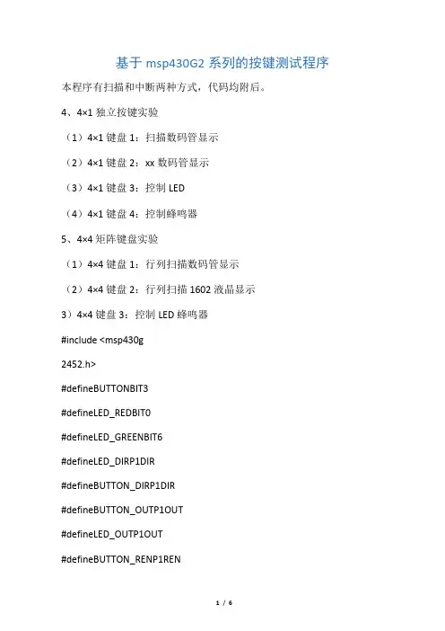
基于msp430G2系列的按键测试程序本程序有扫描和中断两种方式,代码均附后。
4、4×1独立按键实验(1)4×1键盘1:扫描数码管显示(2)4×1键盘2:xx数码管显示(3)4×1键盘3:控制LED(4)4×1键盘4:控制蜂鸣器5、4×4矩阵键盘实验(1)4×4键盘1:行列扫描数码管显示(2)4×4键盘2:行列扫描1602液晶显示3)4×4键盘3:控制LED蜂鸣器#include <msp430g2452.h>#defineBUTTONBIT3#defineLED_REDBIT0#defineLED_GREENBIT6#defineLED_DIRP1DIR#defineBUTTON_DIRP1DIR#defineBUTTON_OUTP1OUT#defineLED_OUTP1OUT#defineBUTTON_RENP1REN#defineBUTTON_ON(P1IN&BIT3)#defineBUTTON_OFF!(P1IN&BIT3)#defineLED_RED_ON()P1OUT|=BIT0#defineLED_RED_OFF()P1OUT&=~BIT0#defineLED_GREEN_ON()P1OUT|=BIT6#defineLED_GREEN_OFF()P1OUT&=~BIT6 volatile unsigned char i=0,flag=0;void main(void){WDTCTL = WDTPW + WDTHOLD; BUTTON_DIR &= ~BUTTON;LED_DIR|= LED_RED+LED_GREEN;BUTTON_REN |= BUTTON;BUTTON_OUT= BUTTON;while(1){/*通过按键改变选择标志位*/if(BUTTON_OFF){flag=!flag;while(BUTTON_OFF);}if(flag){LED_RED_ON();i=10;while(i--)_delay_cycles(500);LED_RED_OFF();LED_GREEN_ON();i=10;while(i--)_delay_cycles(500);LED_GREEN_OFF();}else{LED_OUT |= LED_RED+LED_GREEN;i=10;while(i--)_delay_cycles(500);LED_OUT ^= (LED_RED+LED_GREEN);i=10;while(i--)_delay_cycles(500);}}}/**************该版本编译后的代码与第一个版本是一致的,请看差别在哪儿************/#include <msp430g2452.h>#defineBUTTONBIT3#defineLED_REDBIT0#defineLED_GREENBIT6#defineLED_DIRP1DIR#defineBUTTON_DIRP1DIR#defineBUTTON_OUTP1OUT#defineLED_OUTP1OUT#defineBUTTON_RENP1REN#defineBUTTON_ON(P1IN&BIT3)#defineBUTTON_OFF!(P1IN&BIT3)#defineBIT_SET(x , y)x |= (y)#defineBIT_CLR(x , y)x &=~(y)volatile unsigned char i=0,flag=1;void main(void){WDTCTL = WDTPW + WDTHOLD;BIT_CLR(BUTTON_DIR , BUTTON);BIT_SET(LED_DIR , LED_RED+LED_GREEN);BIT_SET(BUTTON_REN , BUTTON);BIT_SET(BUTTON_OUT , BUTTON);/********************************************************/while(1){/*通过按键改变选择标志位*/if(BUTTON_OFF){flag=!flag;while(BUTTON_OFF);}/*********************************************** ******/if(flag){BIT_SET(LED_OUT , LED_RED);i=10;while(i--)_delay_cycles(500);BIT_CLR(LED_OUT , LED_RED);/*****************************************************/BIT_SET(LED_OUT , LED_GREEN);i=10;while(i--)_delay_cycles(500);BIT_CLR(LED_OUT ,LED_GREEN);}/*****************************************************/ else{BIT_SET(LED_OUT ,LED_RED+LED_GREEN);i=10;while(i--)_delay_cycles(500);/*****************************************************/BIT_CLR(LED_OUT , LED_RED+LED_GREEN);}}}i=10;while(i--)_delay_cycles(500);。
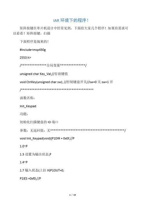
IAR环境下的程序!矩阵按键在单片机设计中经常见到,下面给大家几个程序!如果有需求可以看看!矩阵按键,扫描下面程序是淘来的!#include<msp430g2553.h>/***************全局变量***************/unsigned char Key_Val;//存放键值void CtrlKey(unsigned char sw); //控制键盘开关//sw=0关sw=1开/*******************************************函数名称:Init_Keypad功能:初始化扫描键盘的IO端口参数:无返回值:无********************************************/void Init_Keypad(void){P1DIR = 0x0f;//P1.0~P1.3设置为输出状态,P1.4~P1.7输入状态(上拉H)P1OUT=0;P1IES =0xf0;//P1.7允许中断P1IE=0xf0;//P1.4~P1.7下降沿触发中断P1IFG=0;//中断标志清0Key_Val = 0;}/*******************************************函数名称:Check_Key功能:扫描键盘的IO端口,获得键值参数:无返回值:无********************************************/ //p14\5\6\7接上拉电阻/***************************************key_Val对应键值列:[p14][p15][p16][p17]↓↓↓↓行:[p13]→1234[p12]→5678[p10]→***************************************/void Check_Key(void){unsigned char row ,col,tmp1,tmp2;unsigned char keymap[] = {1,2,3,4,5,6,7,8,9,10,11,12,13,14,15,16};//设置键盘逻辑键值tmp1 = 0x08;for(row = 0;row < 4;row++)//行扫描{P1OUT = 0x0f;//P1.0~P1.3输出全1P1OUT -= tmp1;//P1.0~p1.3输出四位中有一个为0tmp1 >>=1;if((P1IN & 0xf0)<0xf0)//是否P1IN的P1.4~P1.7中有一位为0{tmp2 = 0x10;// tmp2用于检测出哪一位为0for(col = 0;col < 4;col++)//列检测{if((P1IN & tmp2) == 0x00)//是否是该列,等于0为是{Key_Val = keymap[row*4 + col];//获取键值return;//退出循环}tmp2 <<= 1;// tmp2右移1位}}}}/*******************************************函数名称:delay延时约15ms,完成消抖功能参数:无返回值:t= tmp*5*clk根据使用时钟调整tmp值********************************************/void delay(void){unsigned int tmp;for(tmp = 12000;tmp > 0;tmp--);}/*******************************************函数名称:Key_Event功能:检测按键,并获取键值参数:无返回值:无********************************************/void Key_Event(void){unsigned char tmp;P1OUT =0;//设置P1OUT全为0,等待按键输入tmp = P1IN;//获取p1INif((tmp & 0xf0) < 0xf0)//如果有键按下{delay();//消除抖动Check_Key();//调用check_Key(),获取键值}}/***************************************************************** ****控制打开或者关闭键盘中断SW= 0:关闭;ELSE:打开***************************************************************** ****/void CtrlKey(unsigned char sw){if(sw==0)P1IE =0;//关闭端口中断elseP1IE =0xf0; //打开端口中断}/*端口1按键中断*/#pragma vector=PORT1_VECTOR__interrupt void Port(void){if((P1IFG&0xf0)!=0){Key_Event();if(Key_Val!=0)//键值!=0有键按下{CtrlKey(0);//关键盘中断}}P1IFG=0;P1OUT=0;//清中断标志}下面的程序是自己改了下,端口发生了变化!按键矩阵也发生了变化!/***************************************************************** ********************************************************************* *********************/#include<msp430g2553.h>/***************全局变量***************/unsigned char Key_Val;//存放键值void main(){WDTCTL=WDTPW+WDTHOLD;Init_Keypad();_BIS_SR(LPM3_bits + GIE); //最低功耗睡眠while(1);}/*******************************************函数名称:Init_Keypad功能:初始化扫描键盘的IO端口参数:无返回值:无********************************************/ void Init_Keypad(void){P1DIR = 0x38; //P1.0~P1.3设置为输出状态,P1.4~P1.7输入状态(上拉H)P1OUT=0;P1IES =0xC0;//P1.4~P1.7允许中断P1IE=0xC0;//P1.4~P1.7下降沿触发中断P1IFG=0;//中断标志清0Key_Val = 0;}/*******************************************函数名称:Check_Key功能:扫描键盘的IO端口,获得键值参数:无返回值:无********************************************/ //p13\14\15接上拉电阻/***************************************key_Val对应键值列:[p13][p14][p15]↓↓↓行:[p17]→123[p16]→456***************************************/void Check_Key(void){unsigned char row ,col,tmp1,tmp2;unsigned char keymap[] = {1,2,3,4,5,6};//设置键盘逻辑键值tmp1 = 0x08;//从(xx1xxx相左移)for(row = 0;row < 3;row++)//列扫描{P1OUT = 0x38;//P1.3~P1.5输出全1P1OUT -= tmp1;//P1.3~p1.5输出四位中有一个为0tmp1 <<=1;if((P1IN & 0xC0)<0xC0)//是否P1IN的P1.4~P1.7中有一位为0{tmp2 = 0x80;// tmp2用于检测出哪一位为0for(col = 0;col < 2;col++)//行检测{if((P1IN & tmp2) == 0x00)//是否是该列,等于0为是{Key_Val = keymap[row*4 + col];//获取键值return;//退出循环}tmp2 >>= 1;// tmp2右移1位}}}}/*******************************************函数名称:delay功能:延时约15ms,完成消抖功能参数:无返回值:t= tmp*5*clk根据使用时钟调整tmp值********************************************/void delay(void){unsigned int tmp;for(tmp = 12000;tmp > 0;tmp--);}/*******************************************函数名称:Key_Event功能:检测按键,并获取键值参数:无返回值:无********************************************/ void Key_Event(void){unsigned char tmp;P1OUT =0;//设置P1OUT全为0,等待按键输入tmp = P1IN;//获取p1INif((tmp & 0xf0) < 0xf0)//如果有键按下{delay();//消除抖动Check_Key();//调用check_Key(),获取键值}}#pragma vector=PORT1_VECTOR__interrupt void Port(void){delay();if((P1IN&0XC0)<0XC0){Check_Key();switch(Key_Val){case 1:{;自己接相应按键的功能break;}case 2:{;自己接相应按键的功能break;}case 3:{;自己接相应按键的功能break;}case 4:{;自己接相应按键的功能break;}case 5:{;自己接相应按键的功能break;}case 6:{;自己接相应按键的功能break;}default:break;}}P1IFG=0;//清中断标志}下面这个按键用了数组了,存放按键的值,可以应用于密码锁之类的应用!为网上淘来/********************************************************************* ********************************************************************* ******************///此示例程序为中断方式,得到键盘的键值,存放在队列keybuff[10]中//此示例程序没有显示,//键盘的按键按下引起P1口的中断服务程序,得到键盘的键值,保存到键值队列//在其他的中断服务程序中通过键值队列中的数据引导程序的流程#include <msp430x14x.h>unsigned char keybuff[10];unsigned char keypoint=0;void delay(int v){while(v!=0)v--;}unsigned char key(void){unsigned char x=0xff;P1DIR=0X0F;P1OUT=0X01;//扫描第一行if((P1IN&0X70)==0X10)x=0;elseif((P1IN&0X70)==0X20)elseif((P1IN&0X70)==0x40)x=2;else{P1OUT=0X2;//扫描第二行if((P1IN&0X70)==0X10)x=3;elseif((P1IN&0X70)==0X20)x=4;elseif((P1IN&0X70)==0x40)x=5;else{P1OUT=0X4;//扫描第三行if((P1IN&0X70)==0X10)x=6;elseif((P1IN&0X70)==0X20)x=7;elseif((P1IN&0X70)==0x40)else{P1OUT=8;//扫描第四行if((P1IN&0X70)==0X10)x=9;elseif((P1IN&0X70)==0X20)x=10;elseif((P1IN&0X70)==0x40)x=11;}}}return(x);}unsigned char keyj(void){unsigned char x;P1DIR=0x0f;P1OUT=0x0f;//键盘硬件:P10--P13为行线,最上面一根为P10x=(P1IN&0X70);//P14--P16为列线,最左边一根为P14,列线下拉return(x);//无按键,返回0?;有按键返回非0}interrupt[PORT1_VECTOR] voidport1key(void){if(keyj()!=0X00){delay(300);//消抖动if(keyj()!=0X0){keybuff[keypoint]=key();//按键见键值保存到队列keypoint++;//if(keypoint==10)keypoint=0;}}P1OUT=0X0F;P1IFG=0X0;//清除中断标志}void main(void){WDTCTL = WDTPW + WDTHOLD;/*// Stop WDT */P1DIR=0XF;P1OUT=0XF;P1IES=0X0;P1IE=0X70;//列线上升沿允许P1中断_EINT();/*/ Enable interrupts*/while(1){LPM0;_NOP();}}这个是单个按键是,输入端的P1REN要设为1。