《步进电机控制器》.(DOC)
- 格式:doc
- 大小:160.50 KB
- 文档页数:3
CNC可编程步进电机控制器(说明书)一、概述CNC可编程步进电机控制器可与步进电机驱动器、步进电机组成一个完善的步进电机控制系统,能控制多台步进电机多段分时运行。
本控制器采用计算机式的编程语言,拥有输入、输出、计数、循环、条件转移、无条件转移、中断等多种指令。
具有编程灵活、适应范围广等特点,可广泛应用于各种控制的自动化领域。
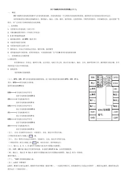
二、技术指标1. 可控制3台步进电机(分时工作)2. 可编100段程序指令(不同的工作状态)3. 5条升降速曲线选择4. 最高输出频率:10 KPPS(脉冲/秒)5. 可接受外接信号控制6. 可控制外部其它部件工作7. 数码显示,可显示当前的运行状态、循环次数、脉冲数等8. 采用超高速单片机控制,采用共阳接法,可直接驱动我厂生产的SH系列步进电机驱动器三、控制器的显示及操作键1.面板说明:8位数码显示:作设定、循环作计数、运行状态、电机工作之用。
指示灯显示输入、输出、方向、脉冲等各种工作。
操作键多为复合键,在不同的状态下表示不同的功能。
2.接线说明:见控制器后盖接线图:( 1 )、OPTO、DIR、CP为步进电机驱动器控制线,此三端分别连至驱动器的OPTO、DIR、CP端:其中:OPTO----所有电机公共阳端接所有驱动器OPTO端DIR0-----0号电机方向电平信号接0号电机驱动器DIR端CP0-------0号电机脉冲信号接0号电机驱动器CP端DIR1-----1号电机方向电平信号接1号电机驱动器DIR端CP1-------1号电机脉冲信号接1号电机驱动器CP端DIR2-----2号电机方向电平信号接2号电机驱动器DIR端CP2-------2号电机脉冲信号接2号电机驱动器CP端( 2 )、启动启动程序自动运行,可接霍尔、光电、接近开关等信号端。
(下降沿有效)相当于面板上键。
( 3 )、停止暂停正自动运行的程序,可接霍尔、光电、接近开关等信号端。
(下降沿有效)相当于面板上的键,再次启动后,程序继续运行。
步进电机控制器说明书本文档旨在提供步进电机控制器的详细说明,包括其功能、使用方法和技术参数等内容。
以下是各章节的具体细化:1. 引言1.1 背景介绍1.2 目的与范围2. 控制器概述2.1 功能特点- 步进电机驱动能力强大,适用于多种应用场景。
- 支持多种通信接口(如RS485、CAN)以及常见编程语言(如C++、Python)。
- 提供丰富而灵活的运动控制模式。
3. 硬件配置要求3.1最低硬件需求CPU:Intel Core i5或更高版本;内存:8GB RAM 或以上;存储空间:100GB 可用磁盘空间;3.2推荐硬件配置CPU: Intel Core i7-9700K;内存:16 GB DDR4;显卡:NVIDIA GeForce RTX2060 Super;4.安装指南4-1安装前准备工作a) 操作系统选择:Windows操作系统推荐Windows10, Linux操作系統建议Ubuntu18+.b) 软件:访问官方网站最新版本的步进电机控制器软件。
4-2安装过程a) 运行安装程序,按照提示完成安装;b) 配置相关参数以适应实际需求。
5. 使用方法5.1 控制器连接与通信设置- 描述如何将控制器与计算机或其他设备进行连接,并配置相应的通信接口和参数。
5.2 步进电机驱动设置- 解释如何使用控制器来驱动步进电机,并提供示例代码和操作指南。
5.3 运动控制模式选择及调整-介绍不同运动模式(位置、速度等)的特点和用法,并说明如何根据需要进行调整。
6.技术规格6-1输入/输出端口提供输入/输出引脚定义表;描述各个引脚功能及其对应编号。
6—2总线协议支持列出所支持总线协议名称;指明每种总线协议在本系统中具体作用。
7.故障排除7_1常见问题解答常见问题并给予解决方案;8.附件:请参考附件文件。
法律名词及注释:1. 步进电机:一种将脉冲信号转换为角位移的执行器,通常由定子和转子组成。
2. 控制器:用于控制步进电机运动的设备或系统。
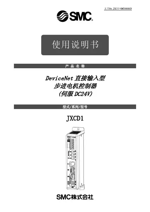
文书No.JXC※-OMT0005CN DeviceNet直接输入型步进电机控制器(伺服DC24V)JXCD11.安全注意事项 (4)2.产品概要 (6)2.1. 产品特点 (6)2.2.型号表示方法 (7)2.3 产品构成 (8)2.4 步骤(直到执行元件作动为止) (9)(1)捆包内容的确认 (9)(2)控制器的安装 (9)(3)控制器的设定 (9)(4)PLC的设定 (9)(5)控制器的配线.连接 (9)(6)电源连接 (10)(7)参数设定 (10)(8)设定数据(运行模块)的设定 (11)(9)试运行 (11)3.产品规格 (12)3.1.规格 (12)3.2 各部位详解 (13)3.3. 外形尺寸图 (14)3.4.安装方法 (16)(1) 安装方法 (16)(2) 接地线的安装 (16)(3) 安装位置 (17)4.初期设定方法 (18)4.1 Node Address/Data Rate设定开关 (18)4.2 硬件配置 (19)4.3 DeviceNet对象 (19)(1)Step Data 对象(Class : 67h) (19)(2)IO 对象(Class : 68h) (20)(3)IO组件接口 (21)(4)IO组件数据格式 (21)5.外部连接图 (23)5.1 PWR:电源插头 (23)5.2 MOT:电机动力插头、ENC:编码器插头 (23)5.3 SI:串行I/O插头 (23)(1)连接示教盒的场合 (23)(2)连接电脑的场合 (24)5.4 DeviceNet通信插头 (24)6.CN1:电源插头详细内容 (25)6.1 电源插头规格 (25)6.2 电线规格 (25)6.3 电源插头的配线 (26)(1)电源部的配线(C24V,M24V,0V) (26)(2)停止开关的配线(EMG) (26)(3)强制解锁开关的配线(LK RLS) (26)6.4 停止回路的配线 (27)(1)停止(推荐回路例) (27)(2)停止(继电器触点(1)) (28)(3)电机动力电源的切断(继电器触点(2)) (29)7.DeviceNet通信插头接口信号配线及通信配线详细内容 308.LED显示详细内容 (31)8.1 LED显示内容 (31)8.2 控制器状态及LED显示内容 (31)9.运行方法 (32)9.1. 概要 (32)9.2 步骤No.指示运行功能 (32)9.3 位置/速度监控功能 (32)9.4 数值指示运行功能 (32)10.存储器地图详细内容 (33)10.1 存储器分配 (33)11.设定数据输入 (42)11.1 步骤数据 (42)11.2 基本参数 (45)11.3 原点复位参数 (47)12.运行说明 (48)12.1 原点复位 (48)12.2 定位运行 (48)12.3 推压运行 (49)(1)推压作动成功时 (49)(2) 推压作动失败时(空转) (49)(3) 推压作动完成后工件仍然移动的场合 (49)12.4 对控制器输入信号的响应时间 (50)12.5 关于运行中的中断方法 (50)13.运行(例) (51)13.1 定位运行 (51)13.2 推压运行 (52)14.运行指示方法 (53)14.1 运行指示方法概要 (53)14.2 步骤No.指示运行功能的运行步骤 (53)[1]电源连接~原点复位 (53)[2] 定位运行 (54)[3]推压运行 (55)[4]短暂停止(HOLD) (55)[5] 复位 (56)[6] 停止 (56)(7) 区域输出 (57)14.3 数值指示运行功能的运行步骤 (58)15.可选项 (59)15.1 执行元件电缆[5m以下] (59)15.2 执行元件电缆[8~20m] (59)15.3 执行元件电缆(传感器.锁对应)[5m以下] (60)15.4 执行元件电缆(传感器.锁对应)[8~20m] (60)15.5 控制器设定组件 (62)15.6 变换电缆 (62)15.7 电源插头 (62)15.8 DeviceNet用通信插头接口 (62)15.9 示教盒 (63)16.与电机控制相关的报警检测详细内容 (64)16.1 报警组的信号输出 (64)16.2 报警内容.对策 (65)17.配线.电缆的注意事项/共通注意事项 (70)18.电动执行器/共通注意事项 (71)18.1 设计注意事项 (71)18.2 安装 (72)18.3 使用注意事项 (73)18.4 使用环境 (74)18.5 维修保养的注意事项 (75)18.6 带锁执行元件的注意事项 (75)19.控制器及其周边设备/个别注意事项 (76)19.1 设计注意事项/选型 (76)19.2 使用注意事项 (77)19.3 安装 (78)19.4 配线 (78)19.5 电源 (79)19.6 接地 (79)19.7 维修保养 (79)20.故障一览表 (80)21. 关于数据接收发送的处理 (85)22.用语集 (86)1.安全注意事项此处所示的注意事项是为了确保您能安全正确地使用本产品,预先防止对您和他人造成危害和伤害而制定的。
Instruction ManualStep Motor Controller – DeviceNet (24 VDC Servo) Series JXCD1##-#The intended use of the step motor controller is to control the movement of an electrical actuator whilst connected to the DeviceNet communication protocol.These safety instructions are intended to prevent hazardous situations and/or equipment damage. These instructions indicate the level of potential hazard with the labels of “Caution,” “Warning” or “Danger.”They are all important notes for safety and must be followed in addition to International Standards (ISO/IEC) *1), and other safety regulations.IEC 60204-1: Safety of machinery - Electrical equipment of machines. (Part 1: General requirements)ISO 10218-1: Robots and robotic devices - Safety requirements for industrial robots - Part 1: Robots.• Refer to product catalogue, Operation Manual and Handling Precautions for SMC Products for additional information. • Keep this manual in a safe place for future reference.CautionCaution indicates a hazard with a low level of risk which, if not avoided, could result in minor or moderate injury.WarningWarning indicates a hazard with a medium level of riskwhich, if not avoided, could result in death or serious injury.DangerDanger indicates a hazard with a high level of risk which, ifnot avoided, will result in death or serious injury.Warning•Always ensure compliance with relevant safety laws and standards.• All work must be carried out in a safe manner by a qualified person in compliance with applicable national regulations.2.1 General specifications ItemSpecificationsCompatible motor Step motor (servo 24 VDC)Power supplyPower supply voltage: 24 VDC +/-10% Currentconsumption100 mA or less (controller)Refer to the actuator specifications for totalpower consumption. Compatible encoderIncremental A/B phase(resolution: 800 pulses / rotation)Memory EEpromLockingUnlocking terminal (applicable to non-exitationmagnetizing lock)Cable length Actuator cable: 20 m maximum Cooling method Air-cooling typeOperatingtemperature0°C to 40°C (version S1.*/S2.*/V1.*/V2.*)0°C to 55°C (version S3.*/V3.* or later)No freezing.Storagetemperature-10o C to 60o C (no freezing)Operating humidity 90% RH or less (No condensation) Insulation resistance 50 MΩ (500 VDC) between the external terminals and caseWeight210 g (Direct mounting type)230 g (DIN rail mounting type)2.2 DeviceNet communication specificationsThe EDS set up file can be downloaded from the SMC website (URL: https:// ).WarningSpecial products (-X) might have specifications different from those shown in this section. Contact SMC for specific drawings.3 Name and function of individual parts4 Installation4.1 InstallationWarning• Do not install the product unless the safety instructions have been read and understood.• Design the installation so that the temperature surrounding the controller is within the specified operating temperature. Leave enough space between the controllers so that the operating temperature of the controllers remains within the specification range.• Mount the controller vertically with 30 mm minimum space on the top and bottom of the controller as shown below.• Allow 60 mm minimum space between the front of the controller and a door (lid) so that the connectors can be connected and disconnected.4.2 Mounting• The controller can be direct mounted (model JXCD17#) using screws or mounted on a DIN rail (model JXCD18#).• When using DIN rail mounting, hook the controller on the DIN rail and press the lever down to lock it.CautionIf the mounting surface for the controller is not flat or is uneven, excessive stress may be applied to the enclosure, which can cause failure. Be sure to mount on a flat surface. 4.3 EnvironmentWarning• Do not use in an environment where corrosive gases, chemicals, saltwater or steam are present.•Do not use in an explosive atmosphere.•Do not expose to direct sunlight. Use a suitable protective cover.•Do not install in a location subject to vibration or impact in excess of the product’s specifications.• Do not mount in a location exposed to radiant heat that would result in temperatures in excess of the product’s specifications.• Avoid mounting the controller near a vibration source, such as a large electromagnetic contactor or circuit breaker on the same panel.• Do not use in an environment with strong magnetic fields present.4.4 WiringCaution•Do not perform wiring while the power is on.•Confirm proper insulation of wiring.• Do not route wires and cables together with power or high voltage cables.•Keep wiring as short as possible to prevent interference from electromagnetic noise and surge voltage.• Do not use an inrush current limited type of power supply for the controller.• Do not connect multiple wires to one connector terminal.Power Supply ConnectorWire the power supply cable to the power supply plug connector, theninsert it into connector PWR on the controller.• Use special screwdriver (Phoenix Contact No. SZS0.4×2.0) to open / close lever and insert the wire into the connector terminal. • Applicable wire size: 20 AWG (0.5 mm 2).Pin No. Terminal Function Description1 C24V Power supply (+) Positive control power.2 M24V Motor power (+) Positive power for the actuator motor supplied via the controller.3 EMG Stop (+)Positive power foremergency stop signal 4 0V Common power (-) Negative common power for M24V, C24V, EMG and LK RLS. 5 - NCN/A6 LK RLSUnlocking (+)Positive power for lock release.ORIGINAL INSTRUCTIONS10 mm minimum(for actuator body size 25 mm or more) ControllerPower Supply Wire specificationsPrepare the wiring according to the following specifications (to be prepared by the user).Communication ConnectorThe wiring method of the special DeviceNet cable and the connection method of the DeviceNet communication connector are shown below. • Use special screwdriver (Phoenix Contact No. SZS0.6×3.5) to tighten the connector terminal screws. Tightening torque = 0.5 to 0.6 N•m. • Applicable wire size: 12 to 24 AWG (0.2 to 2.5 mm 2)Straight type (JXC-CD-T) Right angle type (JXC-CD-S)• DeviceNet compliant twisted pair shielded cables (special cable for DeviceNet) should be used for communication wiring. The maximum cable length depends on the transmission speed and the cable type used. Refer to the operation manual.• Connect a terminating resistor to both ends of the DeviceNet main line. For the terminating resistor, connect a resistor of 121Ω +/-1% and 1/4 W between “CAN_H” and “CAN_L”.Preparation of the terminating resistor should be made by the user.4.5 Ground connection• Place a ground cable with crimped terminal under one of the M4 mounting screws with a shakeproof washer and tighten the screw.CautionThe M4 screw, cable with crimped terminal and shakeproof washer must be prepared by the user.The controller must be connected to Ground to reduce noise. If higher noise resistance is required, ground the 0 V (signal ground). When grounding the 0 V, avoid flowing noise from ground to 0 V.• A dedicated Ground connection must be used. Grounding should be to a D-class ground (ground resistance of 100 Ω maximum).•The cross-sectional area of the ground cable shall be 2 mm 2 minimum. • The Grounding point should be as near as possible to the controller. Keep the grounding cable as short as possible.5.1 Switch setting• Turn off the power supply while setting the switch.• The rotary switch should be set with a small flat blade screwdriver. The node address and communication speed of the DeviceNet communication are set using the setting switches.The node address is set according to the combination of the MSD and LSD setting switches.The communication speed is set using the Data Rate setting switch.Node Address setting Switch setting Node addressMSD (x10) LSD (x1)0 0 0 *20 1 1 (Default) 0 2 2 : : : 6 2 62 6 3 63 6 4 PGM *1: : 9 9*1 When PGM is set, the setting is performed via the DeviceNet network. *2 The default node address is "01" and the default communication speed is "0".6 LED DisplayRefer to the table below for details of the LED status.LEDDescriptionPWROFFPower is not supplied Green LED is ONPower is supplied ALMOFFNormal operationRed LED is ONController Alarm generatedMSOFFController operating voltage is notsuppliedGreen LED is ON Normal operationRed LED is flashing Recoverable internal error. • Rotary switches for node addressand communication speed werechanged after establishing communicationNSOFFController operating voltage is notsuppliedGreen LED is ON DeviceNet communication established. Green LED is flashing DeviceNet communication notestablished.Red LED is flashing DeviceNet connection time out.Red LED is ONNode address duplicated orcommunication error.Refer to the catalogue on the SMC website (URL: https:// ) for the How to Order information.8 Outline Dimensions (mm)Refer to the drawings / operation manual on the SMC website (URL: https:// ) for outline dimensions.9 Maintenance9.1 General MaintenanceCaution• Not following proper maintenance procedures could cause the product to malfunction and lead to equipment damage.• Before performing maintenance, turn off the power supply. Check the voltage with a tester 5 minutes after the power supply is turned OFF. • If any electrical connections are disturbed during maintenance, ensure they are reconnected correctly and safety checks are carried out as required to ensure continued compliance with applicable national regulations.• Do not make any modification to the product.• Do not disassemble the product, unless required by installation or maintenance instructions.Caution• Maintenance should be performed according to the procedure indicated in the Operation Manual.• When equipment is serviced, first confirm that measures are in place to prevent dropping of work pieces and run-away of equipment, etc, then cut the power supply to the system. When machinery is restarted, check that operation is normal with actuators in the correct position.Warning• Perform maintenance checks periodically.• Confirm wiring and screws are not loose. Loose screws or wires maycause unexpected malfunction.• Conduct an appropriate functional inspection and test after completing maintenance. In case of any abnormalities (if the actuator does not move, etc.), stop the operation of the system. Otherwise, an unexpected malfunction may occur and it will become impossible to ensure safety. Operate an emergency stop instruction to confirm safety. • Do not put anything conductive or flammable inside of the controller. • Ensure sufficient space around the controller for maintenance.10 Limitations of Use10.1 Limited warranty and Disclaimer/Compliance Requirements Refer to Handling Precautions for SMC Products.11 Product disposalThis product shall not be disposed of as municipal waste. Check your local regulations and guidelines to dispose of this product correctly, in order to reduce the impact on human health and the environment.12 ContactsRefer to or www.smc.eu for your local distributor / importer.URL: https:// (Global) https://www.smc.eu (Europe) SMC Corporation, 4-14-1, Sotokanda, Chiyoda-ku, Tokyo 101-0021, Japan Specifications are subject to change without prior notice from the manufacturer. © 2021 SMC Corporation All Rights Reserved. Template DKP50047-F-085MFG(DRAIN) Red Blue Black。
步进电机控制器说明书步进电机控制器说明书一、产品概述本文档旨在提供有关步进电机控制器的详细说明。
步进电机控制器是一种用于控制步进电机运动的装置,通过电子方式驱动步进电机实现精确的位置控制。
本控制器具有高精度、可编程性强等特点,适用于各种不同的步进电机应用场景。
二、产品特性本节介绍步进电机控制器的主要特性和功能。
2.1 高精度驱动步进电机控制器采用先进的驱动技术,能够实现高精度的步进电机驱动,可满足精密定位和运动控制需求。
2.2 可编程控制控制器内置丰富的控制算法,支持用户编程,可以根据具体应用需求进行自定义控制,提供更灵活的控制方式。
2.3 多种通信接口本控制器支持多种通信接口,如RS232、RS485、CAN等,便于与其他设备进行通信,实现系统集成和数据传输。
2.4 多种操作模式控制器提供多种操作模式选择,如速度控制、位置控制、力控制等,适应不同应用场景的需求。
2.5 安全保护功能为了确保系统的安全性,本控制器内置了多种安全保护功能,如过流保护、过热保护等,提供有效的保护措施。
三、产品安装和连接本节介绍步进电机控制器的安装和连接方式。
3.1 安装首先,确保电源已经断开。
将控制器固定在合适的位置,通过螺丝固定。
确保控制器和其他设备之间的空间足够,并保持良好的通风。
3.2 连接根据具体应用需求,通过合适的连接线将控制器与步进电机、电源等设备连接。
注意连接的正确性和稳定性,避免接触不良和短路等问题。
四、控制器编程及操作指南本节介绍步进电机控制器的编程和操作方法。
4.1 控制器编程步进电机控制器支持多种编程方式,如C语言、Python等。
用户可以编写相应的代码实现对步进电机的控制和驱动。
4.2 控制器操作指南控制器提供用户友好的操作界面,通过按钮、旋钮等方式进行控制操作。
用户可以根据界面上的指示进行相应的参数设置、模式切换等操作。
五、常见问题与解答本节了一些常见问题,并提供相应的解答。
如果用户遇到其他问题,建议参考本节解答,若问题仍未解决,可联系技术支持人员。

目录1 题目.............................................................2 电路原理图的设计.................................................2.1 步进电机控制电路原理图......................................2.2 LCD显示模块.................................................2.3 L297/298电机驱动模块……………………………………………………2.4 晶振电路和复位电路………………………………………………………2.5 键盘控制模块(加速、减速、正转、反转)................................3 软件系统设计......................................................3.1 软件系统的流程结构..........................................3.2 主程序bujindianji.c模块....................................3.3头文件reg52.h程序模块.......................................3.4 头文件1602.h程序模块.....................................3.5头文件intrins.h程序模块.....................................4 仿真及调试........................................................总论..............................................................参考文献..........................................................致谢.............................................................1题目: 步进电机的单片机控制功能要求:用MCS-51系列单片机作为控制器;采用两相双极性步进电机为控制对象;采用L297/298驱动芯片为步进电机驱动器;用加速、减速、正转、反转4个键进行相应的控制;用LCD 显示步进的电机的工作状态。

步进电机驱动器及细分控制原理(最全)word资料步进电机驱动器及细分控制原理步进电机驱动器原理:步进电机必须有驱动器和控制器才能正常工作。
驱动器的作用是对控制脉冲进行环形分配、功率放大,使步进电机绕组按一定顺序通电。
以两相步进电机为例,当给驱动器一个脉冲信号和一个正方向信号时,驱动器经过环形分配器和功率放大后,给电机绕组通电的顺序为AABB A A B B,其四个状态周而复始进行变化,电机顺时针转动;若方向信号变为负时,通电时序就变为AA B BA A BB,电机就逆时针转动。
随着电子技术的发展,功率放大电路由单电压电路、高低压电路发展到现在的斩波电路。
其基本原理是:在电机绕组回路中,串联一个电流检测回路,当绕组电流降低到某一下限值时,电流检测回路发出信号,控制高压开关管导通,让高压再次作用在绕组上,使绕组电流重新上升;当电流回升到上限值时,高压电源又自动断开。
重复上述过程,使绕组电流的平均值恒定,电流波形的波顶维持在预定数值上,解决了高低压电路在低频段工作时电流下凹的问题,使电机在低频段力矩增大。
步进电机一定时,供给驱动器的电压值对电机性能影响较大,电压越高,步进电机转速越高、加速度越大;在驱动器上一般设有相电流调节开关,相电流设的越大,步进电机转速越高、力距越大。
细分控制原理:在步进电机步距角不能满足使用要求时,可采用细分驱动器来驱动步进电机。
细分驱动器的原理是通过改变A,B相电流的大小,以改变合成磁场的夹角,从而可将一个步距角细分为多步。
定子A转子SNB B BSNA A(a(bAS NB B N S BS NA(c(d图3.2步进电机细分原理图仍以二相步进电机为例,当A、B相绕组同时通电时,转子将停在A、B相磁极中间,如图3.2。
若通电方向顺序按AA AABB BB BB AA AA AA BB BB BB AA,8个状态周而复始进行变化,电机顺时针转动;电机每转动一步,为45度,8个脉冲电机转一周。
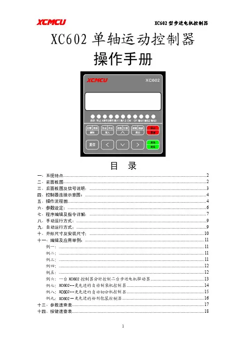
电机,伺服电机可编程控制器AKS-01Z使用说明一、系统特点●控制轴数:单轴;●指令特点:任意可编程(可实现各种复杂运行:定位控制和非定位控制);●最高输出频率:40KHz(特别适合控制细分驱动器);●输出频率分辨率:1Hz;●编程条数:99条;输入/1234、5、6一表示按键。
后面板图及信号说明:后面板图为接线端子,包括:1、CP、CW、OPTP为步进电机驱动器控制线,此三端分别连至驱动器的相应端,其中:CP————步进脉冲信号CW————电机转向电平信号OPTO————前两路信号的公共阳端CP、CW的状态分别对应面板上的指示灯2、启动:启动程序自动运行,相当于面板上的启动键。
3、停止:暂停正在运行的程序,相当于面板上的停止键,再次启动后,程序继续运行。
4、A操作和B操作是本控制器的一大特点:对于步进电机,我们一般进行定量定位控制,如控制电机以一定的速度运行一定的位移这种方式很容易解决,只需把速度量和位移量编程即可。
但还有相当多的控制是不能事先定位的,例如控制步进电机从起始点开始朝一方向运行,直到碰到一行程开关后停止,当然再反向运行回到起始点。
再例如要求步进电机在两个行程开关之间往复运行n次,等等。
在这些操作中,我们事先并不知道步进电机的位移量的具体值,又应当如何编程呢?本控制器利用:“中断操作”,我们称之为“A操作”和“B操作”。
以“A操作”为例,工作流程为:当程序在运行时,如果“A操作”又信号输入,电机作降速停止,程序在此中断,程序记住了中断处的座标,程序跳转到“A操作”入口地址所指定的程序处运行程序。
5、输入1和输入2通过开关量输入端。
6、输出1、输出2和输出3通过开关量输出端。
7、C OM+、COM—输入输出开关量外部电源,本电源为DC12V/0.3A,COM+为正端,COM—为负端,此电源由控制器内部隔离提供。
8、成后按参数分两行显示,第一行显示参数的名称,第二行显示参数数据。
参数修改方式:进入参数设定状态后,首先显示第一行[JF-------]。
TC5510/TC5522/TC5530/TC5522R/TC5530R运动控制器(步进电机控制器)说明书正视图全图左视图后视图右视图TC55-MOD全图注:TC55系列产品,面板尺寸及外壳面膜完全一致,TC55-MOD为选配产品一、概述篇 (3)二、连接篇 (5)三、操作篇 (7)1.自动执行 (11)1.1实际运行 (11)1.2空运行 (11)1.3单步执行 (12)1.4终止程序 (12)2手动操作 (13)2.1手动高速 (13)2.2点动操作 (14)2.3回程序零 (14)2.4回机械零 (14)3程序管理 (16)3.1程序编辑 (16)3.2程序读入 (18)3.3程序删除 (19)3.4程序保存 (20)4参数设置 (20)4.2系统自检 (23)4.3 IO设置 (27)4.4用户管理 (29)四、编程篇 (30)五、附录篇 (52)一、概述篇TC55面板型运动控制器(数控系统)采用高性能32位CPU,驱动装置采用细分步进电机或交流伺服电机,配备液晶显示器,全封闭触摸式操作键盘。
该系统具有可靠性高,精度高,噪音小,操作方便等特点。
本控制器可控制1-3个电机运动,可实现点位、直线插补、圆弧插补等操作。
具有循环、跳转及简易PLC等功能。
简单、清晰的参数带给您方便和快捷的操作。
输入/输出的设置功能可方便您的使用和维修,适用于各类的1-3轴运动装置。
产品特点开机画面可自行修改控制器或上位计算机双模式编程独立24V电源反接保护IO光耦隔离输出短接保护手动正反转可同步外部开关控制简易PLC逻辑参数区密码可设定适用产品类型●数控钻床系统、数控车床系统、数控铣床系统、数控磨床系统●裁剪机控制系统、切割机控制系统、焊接控制系统、点胶机控制系统、送料控制系统●位移台、一维控制平台、二维控制平台、三维控制平台●螺纹机控制系统、锁螺丝机控制系统●喷涂生产线控制系统、装配生产线控制系统、记米器控制系统技术特点●自动执行:可实现实际运行、空运行、单段执行、终止程序、启动和暂停功能●手动操作:可实现手动高、低速、点动操作、回程序零、回机械零等操作。
CL-01A型步进电机控制器说明书可实现:自动制袋机控制器;自动切分机控制器;粉剂包装机控制器;其它任何您想实现的步进电机单轴控制器地址:北京市崇文区光明路13号亿兴大厦503室电话:010-********目录一、系统特点 (1)二、前面板图 (1)三、后面板图及信号说明 (1)四、控制器连接示意图 (2)五、操作说明 (2)六、参数设定 (3)参数速查表 (4)七、 程序编辑及指令详解 (4)指令速查表 (5)八、手动运行方式 (7)九、自动运行方式 (7)十、零点功能 (7)十一、外形尺寸及安装尺寸 (7)十二、编程及应用举例 (8)例一 (8)例二 (8)例三 (9)例四 (9)例五 (9)例六 (10)一、系统特点● 控制轴数 :单轴;● 指令特点 :任意可编程(可实现各种复杂运行:定位控制和非定位控制); ● 最高输出频率 :42.5 KHz(特别适合控制细分驱动器); ● 频率分辨率 :1Hz;● 编程条数 :最大 99 条;● 输入点 :4 个(光电隔离,任意设定启动、暂停、零点;不需外部起停等信号,也可做普通输入); ● 输出点 :2 个(光电隔离);● 一次位移范围 :-9999999 ~ +99999999;● 工作状态 :自动运行状态、手动运行状态、程序编辑状态、参数设定状态;● 升降速曲线 :本控制器最大特点,多条曲线可任意设定(可分别设定升速和降速,满足不同要求, 如:快升慢降、慢生快降);● 显示功能 :8 位数码管可显示坐标、延时、程序等,指示灯可显示 IO 状态、手动/自动状态; ● 自动运行功能 :可编程,通过面板按键和加在端子的电平可控制自动运行的启动和停止等操作; ● 手动运行功能 :可调整位置(手动的点动速度和点动步数可设定);● 参数设定功能 :可设定起跳频率、升降速曲线、反向间隙、手动长度、手动速度和回零速度; ● 程序编辑功能 :可任意插入、删除和修改程序;● 回零点功能 :可双向自动回到零点(有些控制写可以回零,其实是程序零点,本控制机械零点,程 序零点,均可返回);● 编程指令 :共 15 条指令;● 外操作功能 :通过参数设定,可设定任意输入口为启动、暂停或者零点(机械零点); ● 电源 :DC:12V-24V注:次控制器虽然没有市面上已有控制器的A,B 操作功能,但本控制器的AU_LP 指令对未知距离控制提供了更好的方法,如果需要电机做未知距离的往复运动,仅需要两条指令即可完成。
系统特点●控制轴数:单轴;●指令特点:任何可编程(可实现各种复杂运行:定位控制和非定位控制);●最高输出频率:40KHz(特别适合控制细分驱动器);●输出频率分辨率:1Hz;●编程条数:最大99条;●输入点:6个(光电隔离);●输出点:3个(光电隔离);●一次连续位移范围:-7999999~+7999999;●工作状态:自动运行状态、手动运行状态、程序编辑状态、参数设定状态;●升降速曲线:2条(最优化);●显示功能位数:8位数码管显示,手动/自动状态显示、运行/停止状态显示、步数/计数值/程序显示、编辑程序,参数显示、输入/输出状态显示、CP脉冲和方向显示;●自动运行功能:可编辑,通过面板按键和加在端子的电平可控制自动运行的启动和停止等操作;●手动运行功能:可调整位置(手动的点动速度和点动步数可设定);●参数设定功能:可设定起跳频率、升降速曲线、反向间隙、手动长度、手动速度、中断跳转行号和回零速度;●程序编辑功能:可任意插入、删除可修改程序。
具有跳转行号、数据判零、语句条数超长和超短的判错功能;●回零点功能:可双向自动回到零点;●编程指令:共14条指令;外操作功能:通过参数设定和在A操作和B操作端子上加开关可执行外部中断操作;●工作电压:AC90~260V后面板图及信号说明:后面板接线端子。
包括:1.CP、CW、OPTO为步进电机驱动器控制线此三端分别连至驱动器的相应端,其中:CP:步进脉冲信号CW:电机转向电平信号OPTO:前两路信号的公共阳端CP、CW的状态分别对应面板上的指示灯。
2.RUN:启动程序自动运行,相当于面板上的启动键。
3.STOP:暂停正自动运行的程序,相当于面板的停止键。
再次启动后,程序继续运行。
4.A操作和B操作这是本控制器的一大特点:图2后面板图对于步进电机,我们一般进行定量定位控制,如控制电机以一定的速度运行一定的位移这种方式很容易解决,只需要把速度量和位移量编程即可。
YARAK步进驱动器使用说明书 型号:Y2S3060-NY2S3060-N驱动器为等角度恒力矩细分型驱动器,驱动电压DC20-60V,适配4线,6或8出线,电流在3A以下,外径42-86mm的各种型号二相混合式步进电机。
特点◆高性能、低价格◆设有4档等角度恒力矩细分,最高50细分◆最高反应频率可达1Mpps◆步进脉冲超过10ms时,线圈电流自动减半◆双极恒流斩波方式◆光电隔离信号输入◆驱动电流从0.9A/相到3A/相连续可调◆单电源输入,电压范围:DC20-60V性能指标说明最小值典型值最大值单位供电电压20 36 60 VDC输出电流 0.9 — 3 A控制信号输入电流5 10 15 mA步进脉冲频率0 — 1000 KHz步进脉冲最小宽度0.5—— us转向信号最小宽度2 —— us工作环境温度0 — +50 ℃存储温度 -40 — +50 ℃环境湿度—— 90%RH9不能结露—接口与接线示意图注意:1、请不要将电源正负极接反,否则会烧坏驱动器;2、脉冲信号和方向信号为5V,高于5V时请接限流电阻;电机使3、能信号为5—12V输入,给使能信号时电机将停驱动器适配4线、6线和8线电机,接线如下:止;注:六线串行连接时额定电流为电机额定电流0.7倍。
功能设定细分设定细分数 5 10 25 50SW1 ON ON ON OFFSW2 ON ON OFF ON SW3 ON OFF OFF OFF SW4 无效 SW5 OFF :脉冲+方向驱动方式;ON :双脉冲驱动方式 电流设定 电流(A ) 0.9 1.2 1.5 1.8 2.1 2.4 2.7 3.0SW6 OFF ON OFF ON OFF ON OFF ON SW7 OFF OFF ON ON OFF OFF ON ONSW8 OFF OFF OFF OFF ON ON ON ON注:将驱动器印字一面朝上平放,拨码开关朝下为ON !YARAK 驱动器选型Y 2S 30 60-S1 2 3 4 51.系列号Y 系列号 2.相数2S 两相 3.输出相电流(MAX)30 最大输出电流为3.0A 15 最大输出电流为1.5A 4.输入电压(MAX)60 最大输入电压为60V 5.细分模式M 细分数固定为25S 细分数可选2、4、8、16、32、64 N 细分数可选5、10、25、50 O 细分数可选为25、100Y 2S S T 10-S1 2 3 4 51.系列号Y 系列号 2.相数2S 两相3S 三相3.智能驱动器ST 智能驱动器,可自发脉冲,电脑调试 4.输出电流(MAX) 10 10A(MAX),24-80VDC 5 5A(MAX),24-48VDC 5.控制类型 S 支持主机实时控制,但不能程序驻留 PLUS 支持编程下载至驱动器独立运行 Q/I 比PLUS 具有更多输入输出口 BLANK 标准型。
yf19步进电机控制器说明书摘要:一、概述二、产品特点三、技术参数四、工作原理五、安装与使用六、注意事项七、故障排除八、售后服务正文:一、概述yf19 步进电机控制器是一款高性能的步进电机控制设备,适用于各种步进电机的控制。
它能够精确地控制步进电机的旋转角度和转速,广泛应用于各种自动化设备、机器人和数控机床等领域。
二、产品特点1.高精度:yf19 步进电机控制器能够精确地控制步进电机的旋转角度和转速,提高了设备的运动精度。
2.高效率:yf19 步进电机控制器采用优化的控制算法,有效地提高了步进电机的工作效率。
3.稳定性:yf19 步进电机控制器具有优良的抗干扰性能,确保设备在各种工况下的稳定运行。
4.可编程:yf19 步进电机控制器支持编程,用户可以根据实际需求设置控制参数,以满足不同应用场景的需求。
三、技术参数1.控制方式:脉冲控制2.工作电压:DC 24V3.脉冲信号输入:脉冲信号输入正(PUL)、脉冲信号输入负(PUL-)、方向电平信号(DIR)、方向电平信号负(DIR-)4.脱机信号输入:脱机信号输入正(EN)、脱机信号输入负(EN-)5.输出电流:0-2A(可根据用户需求定制)四、工作原理yf19 步进电机控制器通过接收脉冲信号来控制步进电机的旋转。
当控制器接收到脉冲信号时,它会将脉冲信号转换为相应的电流信号,并通过驱动器将电流信号传递给步进电机,从而驱动步进电机旋转。
五、安装与使用1.选购合适的步进电机和驱动器,确保它们与控制器的接口兼容。
2.将步进电机和驱动器连接到控制器上,并确保接线正确无误。
3.接通电源,并确保控制器的工作电压与步进电机和驱动器的工作电压一致。
4.通过编程设置控制器的控制参数,以满足实际应用需求。
5.启动设备,观察步进电机的旋转情况,如有异常,请及时排查故障。
六、注意事项1.控制器应避免暴露在潮湿、高温和有腐蚀性的环境中,以免损坏设备。
2.接线时应确保线缆牢固,避免线缆松动导致设备故障。
步进电机,伺服电机可编程控制器KH-01使用说明一、系统特点●控制轴数:单轴;●指令特点:任意可编程(可实现各种复杂运行:定位控制和非定位控制);●最高输出频率:40KHz(特别适合控制细分驱动器);●输出频率分辨率:1Hz;●编程条数:99条;●输入点:6个(光电隔离);●输出点:3个(光电隔离);●一次连续位移范围:—7999999~7999999;●工作状态:自动运行状态,手动运行状态,程序编辑状态,参数设定状态;●升降速曲线:2条(最优化);●显示功能位数:8位数码管显示、手动/自动状态显示、运行/停止状态显示、步数/计数值/程序显示、编辑程序,参数显示、输入/输出状态显示、CP脉冲和方向显示;●自动运行功能:可编辑,通过面板按键和加在端子的电平可控制自动运行的启动和停止;●手动运行功能:可调整位置(手动的点动速度和点动步数可设定);●参数设定功能:可设定起跳频率、升降速曲线、反向间隙、手动长度、手动速度、中断跳转行号和回零速度;●程序编辑功能:可任意插入、删除可修改程序。
具有跳转行号、数据判零、语句条数超长和超短的判断功能;●回零点功能:可双向自动回到零点;●编程指令:共14条指令;●外操作功能:通过参数设定和编程,在(限位A)A操作和(限位B)B操作端子上加开关可执行外部中断操作;●电源:AC220V(电源误差不大于±15%)。
一、前面板图前面板图包括:1、八位数码管显示2、六路输入状态指示灯3、三路输出状态指示灯4、 CP脉冲信号指示灯5、 CW方向电平指示灯6、按键:共10个按键,且大部分按键为复合按键,他们在不同状态表示的功能不同,下面的说明中,我们只去取功能之一表示按键。
后面板图及信号说明:后面板图为接线端子,包括:1、方向、脉冲、+5V为步进电机驱动器控制线,此三端分别连至驱动器的相应端,其中:脉冲————步进脉冲信号方向————电机转向电平信号+5V————前两路信号的公共阳端CP、CW的状态分别对应面板上的指示灯2、启动:启动程序自动运行,相当于面板上的启动键。
步进电机控制器
步进电机是一种将电脉冲信号转换成相应的角位移的特殊电机,每改变一次通电状态,步进电机的转子就转动一步。
目前大多数步进电机控制器需要主控制器发送时钟信号,并且要至少一个I/O口来辅助控制和监控步进电机的运行情况。
在单片机或DSP的应用系统中,经常配合CPLD或者FPGA来实现特定的功能。
本文介绍通过FPGA实现的步进电机控制器。
该控制器可以作为单片机或DSP的一个直接数字控制的外设,只需向控制器的控制寄存器和分频寄存器写入数据,即可实现对步进电机的控制。
1 步进电机的控制原理步进电机是数字控制电机,它将脉冲信号转变成角位移,即给一个脉冲信号,步进电机就转动一个角度,因此非常适合对数字系统的控制。
步进电机可分为反应式步进电机(简称“VR”)、永磁式步进电机(简称“PM”)和混合式步进电机(简称“HB”)。
步进电机区别于其他控制电机的最大特点是,通过输入脉冲信号来进行控制,即电机的总转动角度由输入脉冲数决定,而电机的转速由脉冲信号频率决定。
步进电机的驱动电路根据控制信号工作,控制信号由各类控制器来产生。
其基本原理作用如下:
①控制换相顺序,通电换相。
这一过程称为“脉冲分配”。
例如:四相步进电机的单四拍工作方式,其各相通电顺序为A—B—C— D。
通电控制脉冲必须严格按照这一顺序分别控制A、B、C、D相的通断,控制步进电机的转向。
如果给定工作方式正序换相通电,则步进电机正转;如果按反序换相通电,则电机就反转。
②控制步进电机的速度。
如果给步进电机发一个控制脉冲,它就转一步,再发一个脉冲,它会再转一步。
两个脉冲的间隔越短,步进电机就转得越快。
调整控制器发出的脉冲频率,就可以对步进电机进行调速。
2 控制器的总体设计
控制器的外部接口电路如图1所示。
各引脚的功能如F:
data[7~O] 控制器与单片机等设备的总线接口;
CS 片选信号,低电平有效;
Wr 写信号,低电平有效;
reset 复位信号,低电平有效;
adr[1~O] 内部寄存器地址信号,与单片机等设备地址线相连;
clk 待分频的时钟,可由FPGA提供;
abcd[3~O] 四相位输出。
控制器的内部原理框图如图2所示,由命令字寄存器(CmcL-reg)、分频系数备份寄存器(fdiv —back)、分频器、相位输出状态机组成。
其中命令字寄存器Cmd—reg组成如下(对应的地址为“00”):
x 未用位。
lni 对控制器初始化为1时有效。
当该位为1时,备份寄存器的数据直接装入分频器的寄存器reg—data[-15~O],装入后由硬件自动置0。
New 当对正在运行的控制器写入新的分频系数时,对该位置1;当下一个分频器输出的clkout 时钟来到时,将fdiv_back写入到reg_data[-15-03中,分频器便按新的
分频系数进行分频。
Manner[1~0] 电动机的驱动方式,用来控制相位输出状态机的输出,“O0”表示单四拍方式,四相位输出为(A—B—C—D);“01”表示双四拍,四相位输出为(AB—
BC—CI)_一DA),八拍(A—AB—B—BC— C—CD_D—DA)。
分频系数备份寄存器(fdiv—back) 两字节寄存器,reg_data[-15-O]为分频器的一个16位寄存器,接收fdiv—back的值,对系统的分频为2~65 536。
对于12 MHz的输入频率,分频后频率为6 MHz-183 Hz,(本设计中,步进电机的启动转速、转距、加速度由使用者根据实际情况自己计算)分频后每个clkout走一个步距角。
对于步距角为1.8。
的电机,可以满足各种速度的要求。
(注:素材和资料部分来自网络,供参考。
请预览后才下载,期待你的好评与关注!)。