JOS 2010 Lab5 报告
- 格式:pdf
- 大小:125.86 KB
- 文档页数:12
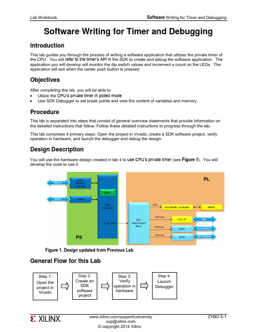
Software Writing for Timer and DebuggingIntroductionThis lab guides you through the process of writing a software application that utilizes the private timer of the CPU. You will refer to the timer’s API in t he SDK to create and debug the software application. The application you will develop will monitor the dip switch values and increment a count on the LEDs. The application will exit when the center push button is pressed.ObjectivesAfter completing this lab, you will be able to:∙ Utilize the CPU’s private timer in polled mode∙ Use SDK Debugger to set break points and view the content of variables and memoryProcedureThis lab is separated into steps that consist of general overview statements that provide information on the detailed instructions that follow. Follow these detailed instructions to progress through the lab. This lab comprises 4 primary steps: Open the project in Vivado, create a SDK software project, verify operation in hardware, and launch the debugger and debug the design.Design DescriptionYou will use the hardware design created in lab 4 to use CPU’s private timer (see Figure 1). You will develop the code to use it.Figure 1. Design updated from Previous LabGeneral Flow for this LabStep 1: Open theproject in VivadoStep 2: Create an SDKsoftware project Step 3: Verify operation in hardware Step 4: Launch DebuggerOpen the Project in Vivado Step 1 e the lab4 project from the last lab or, use the lab4 from the labsolution directory, and save it as lab5. Open the project in Vivado and then export to SDK.1-1-1.If you wish to continue using the design that you created in the previous lab, open the lab4 project from the previous lab, or open the lab4 project in the labsolution directory, and Save it as lab5 to the labs/ directorySince we will be using the private timer of the CPU, which is always present, we d on’t need tomodify the hardware design.1-1-2.Open the Block Design and notice that the status changes to synthesis and implementation out-of-date. Since the bitstream is already generated and will be in the exported directory, we cansafely ignore the warning.unch SDK by selecting File > Export > Export Hardware for SDK in Vivado1-1-4.Check the Launch SDK box only and click OK.You may see the following message when SDK opens. Ignore this warning.Create an SDK Software Project Step 2 2-1.Create a new empty application project called lab5 utilizing already existing standalone_bsp_0 software platform. Import the lab5.c source file.2-1-1.In the Project Explorer in SDK, right click on lab4 and select Close Project2-1-2.Select File > New > Application Project. the project lab5, and for the board Support Package, select Use Existing (standalone_bsp) and click Next.2-1-4.Select Empty Application and click Finish.2-1-5.Select lab5 > src in the project explorer, right-click, and select Import.2-1-6.Expand General category and double-click on File System.2-1-7.Browse to c:\xup\embedded\sources\lab5 folder, select lab5.c and click OK, and then click Finish.You will notice that there are multiple compilation errors. This is expected as the code isincomplete. You will complete the code in this lab.2-2.Refer to the Scutimer API documentation.2-2-1.Select the system.mss tab (if it is not open, open it from standalone > system.mss)2-2-2.Click on Documentation link corresponding to scutimer (ps7_scutimer) peripheral under the Peripheral Drivers section to open the documentation in a default browser window.2-2-3.Click on the Files link to see available files related to the private timer API.2-2-4.Click on the xscutimer.h link to see various functions and data structures available in the API.Look at the XScuTimer_LookupConfig( ) and XScuTimer_CfgInitialize( ) API functions which must be called before the timer functionality can be accessed.Look at various functions available to interact with the timer hardware, includingFigure 2. Useful Functions2-3.Correct the errors.2-3-1.In SDK, in the Problems tab, double-click on the first red unknown type name x for the parse error. This will open the source file and bring you around to the error place.Figure 3. First error2-3-2.Add the include file for the XScuTimer.h. Save the file and the errors should disappear.2-3-3.Scroll down the file and notice that there are few lines intentionally left blank with some guiding comments.Figure 4. Fill in Missing Codeing the API functions list, fill those lines. Save the file and correct errors if any.2-3-5.Scroll down the file further and notice that there are few more lines intentionally left blank with some guiding comments.Figure 5. More Code to be completeding the API functions list, complete those lines. Save the file and correct errors if necessary.Figure 6. Portions of the completed CodeVerify Operation in Hardware Step 3 3-1.Make sure that the JP7 is set to select USB power. Connect the board witha micro-usb cable and power it ON. Establish the serial communicationusing SDK’s Terminal tab.3-1-1.Make sure that the JP7 is set to select USB power.3-1-2.Make sure that a micro-USB cable is connected to the JTAG PROG connector (next to the power supply connector). Turn ON the power.3-1-3.Select the tab. If it is not visible then select Window > Show view > Terminal.3-1-4.Click on and if required, select appropriate COM port (depends on your computer), and configure it with the parameters as shown. (These settings may have been saved from previous lab).3-2.Program the FPGA by selecting Xilinx Tools > Program FPGA and assigning system_wrapper.bit file. Run the TestApp application and verify the functionality.3-2-1.Select Xilinx Tools > Program FPGA.3-2-2.Click on the Search button of the Bitstream field, select system_wrapper.bit, and click OK.3-2-3.Click the Program button to program the FPGA.3-2-4.Select lab5 in Project Explorer, right-click and select Run As > Launch on Hardware (GDB) to download the application, execute ps7_init, and execute lab5.elfDepending on the switch settings you will see LEDs counting with corresponding delay.Flip the DIP switches and verify that the LEDs light with corresponding delay according to theswitch settings. Also notice in the Terminal window, the previous and current switch settings are displayed whenever you flip switches.Figure 7. Terminal window outputLaunch Debugger Step 4 unch Debugger and debug4-1-1.Right-click on the Lab5 project in the Project Explorer view and select Debug As > Launch on Hardware (GDB).The lab5.elf file will be downloaded and if prompted, click Yes to stop the current execution of the program.4-1-2.Click Yes if prompted to change to the Debug perspective.At this point you could have added global variables by right clicking in the Variables tab andselecting Add Global Variables … All global variables would have been displayed and you could have selected desired variables. Since we do not have any global variables, we won’t do it.4-1-3.Double-click in the left margin to set a breakpoint on various lines in lab5.c shown below. A breakpoint has been set when a “tick” and blue circle appear in the left margin beside the linewhen the breakpoint was set.The first breakpoint is where count is initialized to 0. The second breakpoint is to catch if thetimer initialization fails. The third breakpoint is when the program is about to read the dip switch settings. The fourth breakpoint is when the program is about to terminate due to pressing ofcenter push button. The fifth breakpoint is when the timer has expired and about to write to LED.Figure 8. Setting breakpoints4-1-4.Click on the Resume () button to continue executing the program up until the first breakpoint is reached.In the Variables tab you will notice that the count variable may have value other than 0.4-1-5.Click on the Step Over () button or press F6 to execute one statement. As you do step over, you will notice that the count variable value changed to 0.4-1-6.Click on the Resume button again and you will see that several lines of the code are executed and the execution is suspended at the third breakpoint. The second breakpoint is skipped. This is due to successful timer initialization.4-1-7.Click on the Step Over button to execute one statement. As you do step over, you will notice that the dip_check_prev variable value changed to a value depending on the switch settings on your board.4-1-8.Click on the memory tab. If you do not see it, go to Window > Show View > Memory.4-1-9.Click the sign to add a Memory MonitorFigure 9. Monitor memory location4-1-10.Enter the address for the private counter load register (0xF8F00600), and click OK.Figure 10. Monitoring a Memory AddressYou can find the address by looking at the xparameters.h file entry to get the base address(), and find the load offset double-clicking on the xscutimer.h in the outline window followed by double-clicking on the xscutimer_hw.h and then selectingXSCUTIMER_LOAD_OFFSET.Figure 71. Memory Offset4-1-11.Click on the Step Over button to execute one statement which will load the timer register.Notice that the address 0xF8F00604 has become red colored as the content has changed. Verify that the content is same as the value: dip_check_prev*325000000. Y ou will see hexadecimalequivalent (displaying bytes in the order 0 -> 3).E.g. for dip_check_prev = 1; the value is 0x13D92D40; (reversed: 0x402DD913)4-1-12.Click on the Resume button to continue execution of the program. It will stop at the writing to the LED port (skipping fourth breakpoint as center push button as has not occurred).Notice that the value of the counter register is changed from the previous one as the timer wasstarted and the countdown had begun.4-1-13.Click on the Step Over button to execute one statement which will write to the LED port and which should turn OFF the LEDs as the count=0.4-1-14.Double-click on the fifth breakpoint, the one that writes to the LED port, so the program can execute freely.4-1-15.Click on the Resume button to continue execution of the program. This time it will continuously run the program changing LED lit pattern at the switch setting rate.4-1-16.Flip the switches to change the delay and observe the effect.4-1-17.Press center push button and observe that the program suspends at the fourth breakpoint. The timer register content as well as the control register (offset 0x08) is red as the counter value had changed and the control register value changed due to timer stop function call. (In the Memorymonitor, you may need to right click on the address that is being monitored and click Reset torefresh the memory view.)4-1-18.Terminate the session by clicking on the Terminate () button.4-1-19.Exit the SDK and Vivado.4-1-20.Power OFF the board.ConclusionThis lab led you through d eveloping software that utilized CPU’s private timer. You studied the API documentation, used the appropriate function calls and achieved the desired functionality. You verified the functionality in hardware. Additionally, you used the SDK debugger to view the content of variables and memory, and stepped through various part of the code.。

作者单位:041000山西省临汾市中心医院泌尿外科通信作者:闫三华,E -m a i l :49144691@q q.c o m ㊃病例报告㊃X p11.2易位/T F E -3基因融合相关性肾癌1例报告闫三华 许建利d o i :10.3870/j.i s s n .1674-4624.2020.04.014 X p11.2易位/T F E -3基因融合相关性肾癌(简称X p11.2易位性肾癌)是组织病理㊁细胞遗传㊁分子免疫特异的肿瘤,临床较为少见㊂2004年WHO 在肾脏肿瘤分类中首次被归为一个亚型[1],该型肾癌为X 染色体位点上的T F E -3基因发生断裂,同时与P R C C ㊁A S P A ㊁P S F ㊁C L T C 等相关基因易位形成新的融合基因,导致T F E -3基因蛋白的表达异常升高,故被命名为X p11.2易位性肾癌㊂相比其它类型的肾癌,其预后较差[2]㊂由于该肿瘤发病率很低,临床比较少见,通常诊断即为晚期,但病变进展较慢[3]㊂现结合国内外有关文献对我院确诊的1例X p 11.2易位性肾癌进行回顾复习,以进一步提高对该疾病的认识㊂患者,女,49岁,因体检发现右肾占位13d 入院,无腰痛㊁尿频㊁尿急㊁血尿等症状;否认遗传病及化疗史㊂入院查体尿常规阴性,无明显阳性体征㊂体检时腹部彩超提示右肾下极可见大小为5.2c mˑ4.0c mˑ4.2c m 实性等回声团,边界清,可见包膜,部分包膜连续中断,C D F I :内可见少许血流信号㊂入院后行C T 检查,右肾体积增大,下极可见类圆形低密度影,局部突向肾轮廓外,大小为5.2c mˑ3.6c m ,增强扫描动脉期C T 值约83HU ,静脉期C T 值约81HU ,延迟期C T 值约72HU ,周围见环形钙化;左肾形态正常;双侧输尿管及膀胱未见异常,盆腔未见淋巴结肿大(见图1)㊂图1 瘤细胞以腺泡状结构方式排列(H E 染色,ˑ200),部分可见砂砾体结构临床诊断右肾占位,行腹腔镜下右肾癌根治术㊂术后病理回报:送检已剖开右肾1个,大小11.0c mˑ6.5c mˑ4.0c m ,输尿管长9.5c m ,直径0.5c m ,于肾下极可见一5.1c mˑ4.1c mˑ4.1c m 的灰黄结节,切面质脆灰黄,与周围分界尚清㊂病理诊断:(右肾)符合X p11.2易位性肾癌(乳头状肾细胞-T F E -3癌),肿物大小约5.1c mˑ4.1c mˑ4.1c m ,肾被膜受侵,未查见脉管内癌栓及神经侵犯㊂免疫组化:C D 10(+),P A X 8(2+),C D 117(-),E MA (-),C K 7(-),T F E -3(2+0),K i -67(+约5%),R C C (-),C K (+);输尿管断端,肾门血管㊁肾周脂肪囊均阴性㊂周围肾组织间质充血;病理分期:p T 1b N o (见图2)㊂图2 肾实质内见不规则团块影,周边呈环形钙化,可见砂砾体结构讨论 肾癌是最常见的肾脏恶性肿瘤,占恶性肿瘤的85%,占所有成人恶性肿瘤的3%~6%[4]㊂最常见的组织学亚型为透明细胞(60%~75%)㊁乳头状细胞(10%~15%)㊁嫌色细胞(5%)和集合管癌,每一种病理类型都有不同组织病理学和遗传学特点㊂X p 11.2易位性肾癌是一种较为少见的亚型,最早在2004年被WHO 作为一种新的亚型增加到肾癌病理组织学分类中㊂E l l a t i 等[5]第一个发现了这种罕见癌症(12例)㊂其具有独特的遗传学特点,特征是包含X p11.2在内的染色体易位,导致包含T F E -3转录因子基因在内基因融合㊂目前发现的T F E -3基因融合的肾细胞癌至少有5种,包括A S P L -T F E -3㊁P S F -T F E -3㊁C L T C -T F E -3㊁P R C C -T F E -3和N o n o -T F E -3㊂其染色体易位包括t (p11.2;q 25)㊁t (X ;1)(p 11.2;p 34)㊁t (X ;17)(p 11.2;q 23)㊁t (X ;1)(p 11.2;q 21)和i n v (X )(p 11.2;q 12)㊂X p 11.2易位性肾癌具有与透明细胞肾癌和乳头状肾癌相似的形态学特征及临床表现㊂肉眼观肿瘤多为实性,亦可为囊实性,切面可为灰黄㊁灰褐色㊁灰红色等,部分有出血坏死表现,典型的形态学包括透明细胞组成的乳头状结构,常伴有嗜酸性颗粒胞质的瘤细胞组成的巢状结构,间质内偶有砂砾样体㊂R a o 等[6]通过对17例X p 11.2易位性肾癌研究发现其结构具有巢状和乳头状特点,且二者占比分别约为47%和12%,二者均有的约35%;肿瘤细胞特点以透明细胞为主,约占53%,嗜酸性细胞较少,仅为6%,二者都有的占41%㊂临床上,X p 11.2易位(下转第248页)㊃542㊃现代泌尿生殖肿瘤杂志2020年8月第12卷第4期 J C o n t e m p U r o l R e p r o d O n c o l ,A u gu s t 2020,V o l 12,N o .4f i n d i ng s[J].D i a g n I n t e r v R a d i o l,2015,21(5):376-381.[7] R o s e i C A,G i a c o m e l l i L,S a l v e t t i M,e t a l.A d v a n t a g e s o f r e-n i n i n h i b i t i o n i n a p a t i e n t w i t h r e n i n o m a[J].I n t J C a r d i o l, 2015,187:240-242.[8] X u e M,C h e n Y,Z h a n g J,e t a l.R e n i n o m a c o e x i s t i n g w i t ha d r e n a l a d e n o m a d u r i n g p r e g n a n c y:A c a s e r e p o r t[J].O n c o lL e t t,2017,13(5):3186-3190.[9] B a r a j a s L.A n a t o m y o f t h e j u x t a g l o m e r u l a r a p p a r a t u s[J].A m JP h y s i o l,1979,237(5):F333-343.[10] V i d a l-P e t i o t E,B e n s M,C h o u d a t L,e t a l.A c a s e r e p o r t o fr e n i n o m a r a d i o l o g i c a l a n d p a t h o l o g i c a l f e a t u r e s o f t h e t u m o u ra n d c h a r a c t e r i z a t i o n o f t u m o u r-d e r i v e d j u x t a g l o m e r u l a r c e l l si n c u l t u r e[J].J H y p e r t e n s,2015,33(8):1709-1715.[11] D u a n X,B r u n e v a l P,H a mm a d e h R,e t a l.M e t a s t a t i c j u x t a-g l o m e r u l a r c e l l t u m o r i n a52-y e a r-o l d m a n[J].A m J S u r gP a t h o l,2004,28(8):1098-1102.[12] H a g i y a A,Z h o u M,H u n g A,e t a l.J u x t a g l o m e r u l a r c e l l t u-m o r w i t h a t y p i c a l p a t h o l o g i c a l f e a t u r e s:r e p o r t o f a c a s e a n dr e v i e w o f l i t e r a t u r e[J].I n t J S u r g P a t h o l,2020,28(1):87-91.(收稿日期:2020-05-11)(本文编辑:刘倩倩)(上接第245页)性肾癌通常表现为无症状或无痛的肿块,通常在体检或行腹部检查中发现[7]㊂C T平扫可呈低密度㊁等密度影或高密度影,少数患者可见钙化㊂增强不均匀强化,强化程度较肾透明细胞癌弱[8]㊂M R I扫描呈不均匀信号,增强扫描各期均有强化,但低于同期正常肾皮质强化程度㊂对于X p11.2易位性肾癌的治疗方法各有不同;放疗和化疗基本无效,目前主要以手术治疗为主㊂如果肿瘤的体积小于7c m,保留肾单位手术被认为是一种治疗选择[9]㊂免疫治疗对有血行转移的患者有较大价值,包括白细胞介素2和干扰素α等㊂最近的研究表明,雷帕霉素抑制基因的哺乳动物靶点可能对X p11.2易位性肾癌有效[5,10]㊂此外,索拉非尼㊁依维莫司等分子靶向药物对该肿瘤的治疗也有一定疗效[11]㊂X p11.2易位性肾癌的预后目前争议较多,缺乏大数据随访㊂K l a t t e 等[12]报道了该病成人的平均生存期可达2年,而小儿的平均生存期为6.3年㊂该肿瘤患者的预后影响因素众多,如种族㊁年龄㊁临床分期,甚至治疗方式选择㊂应该建立大规模及系统性研究,制定统一诊疗标准㊂本例患者处于T1b N o M o 期,经过24个月的随访,患者基本情况良好,无复发或转移的症状与体征㊂但远期的预后效果仍有待长期的随访㊂参考文献[1] L o p r z-B e l t r a n A,S c a r p e l l i M,M o n t i r o n i R,e t a l.2004WH Oc l a s s i f i c a t i o n o f t h e r e n a l t u m o r s o f t h e ad u l t s[J].E u r U r o l,2006,49(5):798-805.[2]Q i u R,B i n g G,Z h o u X J.X p11.2t r a n s l o c a t i o n r e n a l c e l lc a r c i n o m a s h a v e a p o o r e r p r o g n o s i s t h a n n o n-X p11.2t r a n s l o-c a t i o n c a r c i n o m a s i n c h i ld re n a n d y o u n g a d u l t s:a m e t a-a n a l y-s i s[J].I n t J S u r g P a t h o l,2010,18(6):458-464. [3] S r i g l e y J R,D e l a h u n t B.U n c o mm o n a n d r e c e n t l y d e s c r i b e dr e n a l c a r c i n o m a s[J].M o d P a t h o l,2009,22S u p p l2:S2-s23.[4]V e r h o e s t G,V e i l l a r d D,G u i l léF,e t a l.R e l a t i o n s h i p b e-t w e e n a g e a t d i a g n o s i s a n d c l i n i c o p a t h o l o g i c f e a t u r e s o f r e n a lc e l l c a r c i n o m a[J].E u r U r o l,2007,51(5):1298-1304.[5] E l l a t i R T,A b u k h i r a n I,A l q a s e m K,e t a l.C l i n i c o p a t h o l o g i cf e a t u r e s o f t r a n s l o c a t i o n r e n a l c e l l c a r c i n o m a[J].C l i n G e n i t o-u r i n C a n c e r,2017,15(1):112-116.[6] R a o Q,W i l l i a m s o n S R,Z h a n g S,e t a l.T F E3b r e a k-a p a r tF I S H h a s a h i g h e r s e n s i t i v i t y f o r X p11.2t r a n s l o c a t i o n-a s s o-c i a t ed re n a l c e l l c a r c i n o m a c o m p a r e d w i t h T F E3o r c a t h e p s i nK i mm u n o h i s t o c h e m i c a l s t a i n i n g a l o n e:e x p a n d i n g t h e m o r-p h o l o g i c s p e c t r u m[J].A m J S u r g P a t h o l,2013,37(6):804-815.[7] A r m a h H B,P a r w a n i A V.X p11.2t r a n s l o c a t i o n r e n a l c e l l c a-r c i n o m a.A r c h P a t h o l L a b M e d,2010,134(1):124-9.[8] H e J,G a n W,L i u S,e t a l.D y n a m i c c o m p u t e d l o m o g r a p h i ca d u l t r e n a l c e l l c a r c i n o m a a s s c o c i a t e d w i t h X p11.2t r a n s l o c a-t i o n/t f e3g e n e f u s i o n s:c o m p a r i s o n w i t h c l e a r c e l l c e l l r e n a lc e l l c a r c i n o m a[J].J C o m p u t A s s i s t T o m o g r,2015,39(5):730-736.[9]S o n g H C,S u n N,Z h a n g W P,e t a l.B i o l o g i c a l c h a r a c t e r i s t i c so f p e d i a t r i c r e n a l c e l l a r c i n o m a a s s o c i a t e d w i t h X p11.2t r a n s-l o c a t i o n s/T F E3g e n e f u s i o n s[J].J P e d i a t r S u r g,2014,49(4):539-542.[10] K a k o k i K,M i y a t a Y,M o c h i z u k i Y,e t a l.L o n g-t e r m t r e a t-m e n t w i t h s e q u e n t i a l m o l e c u l a r t a r g e t e d t h e r a p y f o r X p11.2t r a n s l o c a t i o n r e n a l c e l l c a r c i n o m a:A c a s e r e p o r t a n d r e v i e wo f t h e l i t e r a t u r e[J].C l i n G e n i t o u r i n C a n c e r,2017,15(3): e503-e506.[11]S u d o u r-B o n n a n g e H,L e r o y X,C h a u v e t M P,e t a l.C u t a n e-o u s m e t a s t a s e s d u r i n g a n a g g r e s s i v e c o u r s e o f X p11.2t r a n s-l o c a t i o n r e n a l c e l l c a r c i n o m a i n a t e e n a g e r[J].P e d i a t r B l o o dC a n c e r,2014,61(9):1698-1700.[12] K l a t t e T,S t r e u b e l B,W r b a F,e t a l.R e n a l c e l l c a r c i n o m aa s s o c i a t e d w i t h t r a n s c r i p t i o n f a c t o r E3e x p r e s s i o n a n d X p11.2t r a n s l o c a t i o n:I n c i d e n c e,c h a r a c t e r i s t i c s,a n d p r o g n o s i s[J].A m J C l i n P a t h o l,2012,137(5):761-768.(收稿日期:2019-10-17)(本文编辑:刘倩倩)㊃842㊃现代泌尿生殖肿瘤杂志2020年8月第12卷第4期J C o n t e m p U r o l R e p r o d O n c o l,A u g u s t2020,V o l12,N o.4。
Interlaboratory T est …Microbial barrier testing of packa ging materials for medical devices which are tobe ster ili ze d“according to DIN 58953-6:2010Test re portJanuary 2013Author: Daniel ZahnISEGA Forschungs- und Untersuchungsgesellschaft mbHTest report Page 2 / 15Table of contentsSeite1.General information on the Interlaboratory Test (3)1.1 Organization (3)1.2 Occasion and Objective (3)1.3 Time Schedule (3)1.4 Participants (4)2.Sample material (4)2.1 Sample Description and Execution of the Test (4)2.1.1 Materials for the Analysis of the Germ Proofness under Humidityaccording to DIN 58953-6, section 3 (5)2.1.2 Materials for the Analysis of the Germ Proofness with Air Permeanceaccording to DIN 58953-6, section 4 (5)2.2 Sample Preparation and Despatch (5)2.3 Additional Sample and Re-examination (6)3.Results (6)3.1 Preliminary Remark (6)3.2 Note on the Record of Test Results (6)3.3 Comment on the Statistical Evaluation (6)3.4 Outlier tests (7)3.5 Record of Test Results (7)3.5.1 Record of Test Results Sample F1 (8)3.5.2 Record of Test Results Sample F2 (9)3.5.3 Record of Test Results Sample F3 (10)3.5.4 Record of Test Results Sample L1 (11)3.5.5 Record of Test Results Sample L2 (12)3.5.6 Record of Test Results Sample L3 (13)3.5.7 Record of Test Results Sample L4 (14)4.Overview and Summary (15)Test report Page 3 / 15 1. General Information on the Interlaboratory Test1.1 OrganizationOrganizer of the Interlaboratory Test:Sterile Barrier Association (SBA)Mr. David Harding (director.general@)Pennygate House, St WeonardsHerfordshire HR2 8PT / Great BritainRealization of the Interlaboratory Test:Verein zur Förderung der Forschung und Ausbildung fürFaserstoff- und Verpackungschemie e. V. (VFV)vfv@isega.dePostfach 10 11 0963707 Aschaffenburg / GermanyTechnical support:ISEGA Forschungs- u. Untersuchungsgesellschaft mbHDr. Julia Riedlinger / Mr. Daniel Zahn (info@isega.de)Zeppelinstraße 3 – 563741 Aschaffenburg / Germany1.2 Occasion and ObjectiveIn order to demonstrate compliance with the requirements of the ISO 11607-1:2006 …Packaging for terminally sterilized medical devices -- Part 1: Requirements for materials, sterile barrier systems and packaging systems“ validated test methods are to be preferably utilized.For the confirmation of the microbial barrier properties of porous materials demanded in the ISO 11607-1, the DIN 58953-6:2010 …Sterilization – Sterile supply – Part 6: Microbial barrier testing of packaging materials for medical devices which are to be sterilized“ represents a conclusive method which can be performed without the need for extensive equipment.However, since momentarily no validation data on DIN 58953-6 is at hand concerns emerged that the method may lose importance against validated methods in a revision of the ISO 11607-1 or may even not be considered at all.Within the framework of this interlaboratory test, data on the reproducibility of the results obtained by means of the analysis according to DIN 58953-6 shall be gathered.1.3 Time ScheduleSeptember 2010:The Sterile Barrier Association queried ISEGA Forschungs- und Unter-suchungsgesellschaft about the technical support for the interlaboratory test.For the realization, the Verein zur Förderung der Forschung und Ausbildungfür Faserstoff- und Verpackungschemie e. V. (VFV) was won over.November 2010: Preliminary announcement of the interlaboratory test / Seach for interested laboratoriesTest report Page 4 / 15 January toDecember 2011: Search for suitable sample material / Carrying out of numerous pre-trials on various materialsJanuary 2012:Renewed contact or search for additional interested laboratories, respectively February 2012: Sending out of registration forms / preparation of sample materialMarch 2012: Registration deadline / sample despatchMay / June 2012: Results come in / statistical evaluationJuly 2012: Despatch of samples for the re-examinationSeptember 2012: Results of the re-examination come in / statistical evaluationNovember 2012: Results are sent to the participantsDecember 2012/January 2013: Compilation of the test report1.4 ParticipantsFive different German laboratories participated in the interlaboratory test. In one laboratory, the analyses were performed by two testers working independently so that six valid results overall were received which can be taken into consideration in the evaluation.To ensure an anonymous evaluation of the results, each participant was assigned a laboratory number (laboratory 1 to laboratory 6) in random order, which was disclosed only to the laboratory in question. The complete laboratory number breakdown was known solely by the ISEGA staff supporting the proficiency test.2. Sample Material2.1 Sample Description and Execution of the TestUtmost care in the selection of suitable sample material was taken to include different materials used in the manufacture of packaging for terminally sterilized medical devices.With the help of numerous pre-trials the materials were chosen covering a wide range of results from mostly germ-proof samples to germ permeable materials.Test report Page 5 / 15 2.1.1 Materials for the Analysis of Germ Proofness under Humidity according to DIN 58953-6, section 3:The participants were advised to perform the analysis on the samples according to DIN 58953-6, section 3, and to protocol their findings on the provided result sheets.The only deviation from the norm was that in case of the growth of 1 -5 colony-forming units (in the following abbreviated as CFU) per sample, no re-examination 20 test pieces was performed.2.1.2 Materials for the Analysis of Germ Proofness with Air Permeance according to DIN 58953-6, section 4:The participants were advised to perform the analysis on the samples according to DIN 58953-6, section 4, and to protocol their findings on the provided result sheets.2.2 Sample Preparation and DespatchFor the analysis of the germ proofness under humidity, 10 test pieces in the size of 50 x 50 mm were cut out of each sample and heat-sealed into a sterilization pouch with the side to be tested up.Out of the 10 test pieces, 5 were intended for the testing and one each for the two controls according to DIN 58953-6, sections 3.6.2 and 3.6.3. The rest should remain as replacements (e.g. in case of the dropping of a test piece on the floor etc.).For the analysis of the germ proofness with air permeance, 15 circular test pieces with a diameter of 40 mm were punched out of each sample and heat-sealed into a sterilization pouch with the side to be tested up.Test report Page 6 / 15 Out of the 15 test pieces, 10 were intended for the testing and one each for the two controls according to DIN 58953-6, section 4.9. The rest should remain as replacements (e.g. in case of the dropping of a test piece on the floor etc.).The sterilization pouches with the test pieces were steam-sterilized in an autoclave for 15 minutes at 121 °C and stored in an climatic room at 23 °C and 50 % relative humidity until despatch.2.3 Additional Sample and Re-examinationFor the analysis of the germ proofness under humidity another test round was performed in July / August 2012. For this, an additional sample (sample L4) was sent to the laboratories and analysed (see 2.1.2). The results were considered in the evaluation.For validation or confirmation of non-plausible results, occasional samples for re-examination were sent out to the laboratories. The results of these re-examinations (July / August 2012) were not taken into consideration in the evaluation.3. Results3.1 Preliminary RemarkSince the analysis of germ proofness is designed to be a pass / fail – test, the statistical values and precision data were meant only to serve informative purposes.The evaluation of the materials according to DIN58953-6,sections 3.7and 4.7.6by the laboratories should be the most decisive criterion for the evaluation of reproducibility of the interlaboratory test results. Based on this, the classification of a sample as “sufficiently germ-proof” or “not sufficiently germ-proof” is carried out.3.2 Note on the Record of Test Results:The exact counting of individual CFUs is not possible with the required precision if the values turn out to be very high. Thus, an upper limit of 100 CFU per agar plate or per test pieces, respectively, was defined. Individual values above this limit and values which were stated with “> 100” by the laboratories, are listed as 100 CFU per agar plate or per test piece, respectively, in the evaluation.Test report Page 7 / 153.3 Comment on the Statistical EvaluationThe statistical evaluation was done based on the series of standards DIN ISO 5725-1ff.The arithmetic laboratory mean X i and the laboratory standard deviation s i were calculated from the individual measurement values obtained by the laboratories.The overall mean X of the laboratory means as well as the precision data of the method (reproducibility and repeatability) were determined for each sample3.4 Outlier testsThe Mandel's h-statistics test was utilised as outlier test for differences between the laboratory means of the participants.A laboratory was identified as a “statistical outlier” as soon as an exceedance of Mandel's h test statistic at the 1 % significance level was detected.The respective results of the laboratories identified as outliers were not considered in the statistical evaluation.3.5 Record of Test ResultsOn the following pages, the records of the test results for each interlaboratory test sample with the statistical evaluation and the evaluation according to DIN 58953-6 are compiled.Test report Page 8 / 153.5.1 Record of Test Results Sample F1Individual Measurement values:Statistical Evaluation:Comment:Laboratory 4, as an outlier, has not been taken into consideration in the statistical Evaluation.Outlier criterion: Mandel's h-statistics (1 % level of significance)Overall mean X:91.0CFU / agar plateRepeatability standard deviation s r:17.9CFU / agar plateReproducibility standard deviation s R:19.8CFU / agar plateRepeatability r:50.0CFU / agar plateRepeatability coefficient of variation:19.6%Reproducibility R:55.5CFU / agar plateReproducibility coefficient of variation:21.8%Evaluation according to DIN 58953-6, Section 3.7:Lab. 1 - 6:Number of CFU > 5, i.e. the material is classified as not sufficiently germ-proof.Conclusion:All of the participants, even the Laboratory 4 which was identified as an outlier, came to the same results and would classify the sample material as “not sufficiently germ-proof”Test report Page 9 / 153.5.2 Record of Test Results Sample F2Individual Measurement values:Statistical Evaluation:Comment:Laboratory 4, as an outlier, has not been taken into consideration in the statistical Evaluation.Outlier criterion: Mandel's h-statistics (1 % level of significance)Overall mean X:0CFU / agar plateRepeatability standard deviation s r:0CFU / agar plateReproducibility standard deviation s R:0CFU / agar plateRepeatability r:0CFU / agar plateRepeatability coefficient of variation:0%Reproducibility R:0CFU / agar plateReproducibility coefficient of variation:0%Evaluation according to DIN 58953-6, Section 3.7:Lab. 1 – 3:Number of CFU = 0, i.e. the material is classified as sufficiently germ-proofLab. 4:Number of CFU ≤ 5, i.e. a re-examination on 20 test pieces would have to be done Lab. 5 – 6:Number of CFU = 0, i.e. the material is classified as sufficiently germ-proofConclusion:All of the participants, except for the Laboratory 4 which was identified as an outlier, came to the same results and would classify the sample material as “sufficiently germ-proof”.Test report Page 10 / 153.5.3 Record of Test Results Sample F3Individual Measurement values:Statistical Evaluation:Overall mean X:30.1CFU / agar plateRepeatability standard deviation s r:17.2CFU / agar plateReproducibility standard deviation s R:30.9CFU / agar plateRepeatability r:48.2CFU / agar plateRepeatability coefficient of variation:57.1%Reproducibility R:86.5CFU / agar plateReproducibility coefficient of variation:103%Evaluation according to DIN 58953-6, Section 3.7:Lab. 1 - 4:Number of CFU > 5, i.e. the material is classified as not sufficiently germ-proof. Lab. 5:Number of CFU = 0, i.e. the material is classified as sufficiently germ-proof. Lab. 6:Number of CFU > 5, i.e. the material is classified as not sufficiently germ-proof.Conclusion:Five of the six participants came to the same result and would classify the sample as “not sufficiently germ-proof”. Only laboratory 5 would classify the sample material as “sufficiently germ-proof”.Test report Page 11 / 153.5.4 Record of Test Results Sample L1Individual Measurement values:Statistical Evaluation:Overall mean X:0.09CFU / test pieceRepeatability standard deviation s r:0.32CFU / test pieceReproducibility standard deviation s R:0.33CFU / test pieceRepeatability r:0.91CFU / test pieceRepeatability coefficient of variation:357%Reproducibility R:0.93CFU / test pieceReproducibility coefficient of variation:366%Evaluation according to DIN 58953-6, Section 4.7:Lab. 1 - 6:Number of CFU < 15, i.e. the material is classified as sufficiently germ-proof.Conclusion:All participants came to the same result and would classify the sample as “sufficiently germ-proof”.Test report Page 12 / 153.5.5 Record of Test Results Sample L2Individual Measurement values:Statistical Evaluation:Overall mean X:0.73CFU / test pieceRepeatability standard deviation s r: 1.10CFU / test pieceReproducibility standard deviation s R: 1.18CFU / test pieceRepeatability r: 3.07CFU / test pieceRepeatability coefficient of variation:151%Reproducibility R: 3.32CFU / test pieceReproducibility coefficient of variation:163%Evaluation according to DIN 58953-6, Section 4.7:Lab. 1:Number of CFU > 15, i.e. the material is classified as not sufficiently germ-proof. Lab. 2 - 6:Number of CFU < 15, i.e. the material is classified as sufficiently germ-proof.Conclusion:Five of the six participants came to the same result and would classify the sample as “sufficiently germ-proof”. Only laboratory 1 exceeds the limit value slightly by 1 CFU, so that the sample would be classified as “not sufficiently germ-proof”.Test report Page 13 / 153.5.6 Record of Test Results Sample L3Individual Measurement values:Statistical Evaluation:Overall mean X:0.36CFU / test pieceRepeatability standard deviation s r: 1.00CFU / test pieceReproducibility standard deviation s R: 1.06CFU / test pieceRepeatability r: 2.79CFU / test pieceRepeatability coefficient of variation:274%Reproducibility R: 2.98CFU / test pieceReproducibility coefficient of variation:293%Evaluation according to DIN 58953-6, Section 4.7:Lab. 1 - 6:Number of CFU < 15, i.e. the material is classified as sufficiently germ-proof.Conclusion:All participants came to the same result and would classify the sample as “sufficiently germ-proof”.Test report Page 14 / 153.5.7 Record of Test Results Sample L4Individual Measurement values:Statistical Evaluation:Overall mean X:35.1CFU / test pieceRepeatability standard deviation s r:18.8CFU / test pieceReproducibility standard deviation s R:42.6CFU / test pieceRepeatability r:52.7CFU / test pieceRepeatability coefficient of variation:53.7%Reproducibility R:119CFU / test pieceReproducibility coefficient of variation:122%Evaluation according to DIN 58953-6, Section 4.7:Lab. 1 - 3:Number of CFU > 15, i.e. the material is classified as not sufficiently germ-proof. Lab. 4:Number of CFU < 15, i.e. the material is classified as sufficiently germ-proof. Lab. 5 - 6:Number of CFU > 15, i.e. the material is classified as not sufficiently germ-proof.Conclusion:Five of the six participants came to the same result and would classify the sample as“not sufficiently germ-proof”.Test report Page 15 / 15 4. Overview and SummarySummary:In case of four of the overall seven tested materials, a 100 % consensus was reached regarding the evaluation as“sufficiently germ-proof”and“not sufficiently germ-proof”according to DIN 58 953-6.As for the other three tested materials, there were always 5 concurrent participants out of 6 (83 %). In each case, only one laboratory would have evaluated the sample differently.It is noteworthy that the materials about the evaluation of which a 100 % consensus was reached were the smooth sterilization papers. The differences with one deviating laboratory each occurred with the slightly less homogeneous materials, such as with the creped paper and the nonwoven materials.。
LAB 5: Biological Macromolecules Tests Introduction:There are four main classes of molecules which are essential to the biology of life: carbohydrates, lipids , proteins and nucleic acids. They are called macromolecules due to the large. IKI solution react with starch to turn from yellow-brown to blue-black. Benedict’ reagent reacts with reducingsugars( glucose, lactose etc) to turn from blue-green to orange, red and eventually brown. A solution of glucose turns to a brick red color. Sudan III is a fat-soluble dye that is used to stain lipids. If the sample contains lipids, they will dissolves in the Sudan III and will be carried outside of a defined perimeter. Biured reagent reacts with a peptide bond to turn from a blue to a violet color.In this lab , you will learn about the chemistry and function of these molecules and how to identify carbohydrates, lipids and proteins using Benedict’s reagent, IKI, Sudan III and biuret reagent.Materials and Methods:1.Carbohydrates:1)test for sugar using Benedict’ solutionMaterials: Marker pen, Pipette (CRAGONLAB ), 10 test tubes in test tube rack, Test tube clamp, water bath;Stock bottles of: Benedict’s solution, distilled water(d H2O), 1% glucose solution, 1% maltose solution, 1% lactose solution, 1% sucrose solution, 1% fructose solution, 1% starch solution, orange juice, soda water, unsweetened soda water.Methods:a)Prepare a data table as Data Table 5-1 shown below. Record predictedresults based on the truth that whether the sample contain reducingsugars and actual observations in the table.b)Prepare a hot water bath: set the water bath to 98 〬C .c)Using the marker pen , number the test tubes 1-10 and group number onthe top of test tube.d)Pipe 0.5 ml of the correct stock solutions into the test tubes as describedin Data Table 5-1.e)Add 2 ml of Benedict’s solution to each test tube, agitate the mixture byshaking the tubes from side to side by hand and record the color of the mixture in the column “Initial Color”.f)Heat the tubes in the 98〬C water bath for 20 minutes. Put the tubes in thehole of the water bath. After 20 minutes , remove the tubes with test tube clamp and record any color changes that have taken place in the column “Color after heating” and “Color after shaking”. Also record the conclusions regarding the presence or absence of reducing carbohydrates.Results:The results are filled in the Data Table 5-1. The observations of the results see Fig.1,Fig.2,Fig.3.Discussion:We find that the tube that contains sucrose do produce a brick red precipitate after heating. I think one of the reason is that the sucrose is not pure and contains some reducing sugar.Questions: A. What can be conclude from the experiment?Answer: Glucose, maltose, lactose and fructose are reducing carbohydrates and sucrose and starch are not reducing carbohydrates. Something that contains reducing carbohydrates and is mixed with Benedict’s reagent and is heated will produce a brick red precipitate. Orange juice ,soda water contain reducing carbohydrates but distilled water and unsweetened soda water not.2) Test for starch using Iodine-KI Reagent(IKI)Materials: Marker pen, Glass slides, Cover slip, Compound microscopy(Nikon E100), Pipette:IKI solution in tube, Stock bottles of water, Potato, Onion, KnifeMethods:a)Hypothesis: A potato has the most starchb)Cut open a white potato and use the knife to slice as thin a larger of cellsas possible from the inside of the potato. Trim the slice to about 0.5cm2and place it on a microscope slide which has been added a drop of distilled water. Then cover it with a microscope slide cover slip.c)Use a pipette to add one or two drops of IKI solution in tube at one edge ofthe cover slip. Then hold a small piece of paper towel against the opposite edge of the cover slip so capillary action will move the IKI stain under the cover and into the potato slice.d)Place the slide under the compound microscope lower power and higherpower. Take a picture of these (See Fig.4, Fig.5).e)Repeat steps b) through d) above using the inner cells of onion in place ofpotato.f)Record drawings and magnification in the report (See Fig.6).Results: A potato has the most starch. Our hypothesis is right. Observation for potato slide : ball-chained starch is blue or heavy blue-black. For onion: brown onion cell and almost no blue-black starch.Discussion:Questions: A. Which vegetable has the most starch?Answer: A potato has the most starch.2.Lipids: Sudan III testMaterials: Marker pen, Dropper bottles of Sudan III ,Filter paper, Aluminum foil;Dropper bottles of : Distilled water, Vegetable oil(Fu Lin Men edible oil, containing transgenic ingredients) , Onion juice, Unsweetened Soda water, Pipette, Tube rack.Methods:a)Prepare a data table as Data Table 5-2 shown below. Record ahypothesis for each sample treatment listed as to whether it will or will not contain the test substance, which in this case is lipid.b)Palace a filter paper onto the piece of aluminum foil to prevent staining ofthe work surface. Use the pipette to place 4 separate drops of Sudan III onto different areas of the filter paper. Allow the drops to dry.c)Use a pencil to trace an outline around each of the dried Sudan III drops.Make a marker for each of the Sudan III drops.(See Fig.7)d)Use a separate pipette to draw up a small amount of dH2O . Add a droponto the dH2O circle.e)Use a separate pipette to draw up a small amount of vegetable oil . Add adrop onto the vegetable oil circle.f)Use a separate pipette to draw up a small amount of onion juice . Add adrop onto the juice circle.g)Use a separate pipette to draw up a small amount of soda water . Add adrop onto the soda water circle.h)Wait a few minutes and then record the results in the table. Observewhether the stain stayed inside the circle drawn with the pencil. If the stain dissolves in the substances and moves outside the pencil line, thisindicates that the tested substance contains lipids.Results: The observations are filled in the Data Table 5-2: only the stain moved outside the circle which was added a drop of oil.(See Fig.8) The oil contains lipids and distilled water, onion juice and soda water not.Discussion:Question: A. What can be concluded from this experiment ?Answer: Only the vegetable oil contains lipids and distilled water, onion juice and soda water not.3.Proteins: Biuret testMaterials and Methods:Materials: Marker pen , 5 test tubes in test tube racks, pipette.Stock bottles of: Biuret reagent, distilled water, 1% starch solution, 1% glucose solution, egg albumin, soda drinkMethods:a)Prepare a data table as 5-3 shown below. Record a hypothesis for eachsample treatment listed as to whether it will or will not contain protein.b)Use the marker pen to number the test tubes 1-5.c)Pipet 0.5 ml of the correct stock solutions into the test tubes as describedin Data Table 4-3.d)Add 2 ml of Biuret reagent to each test tube, agitate the mixture byshaking the tubes from side to side .e)Wait 2 minutes and then recorder the color of the mixture in Data Table 5-3 in the column “Color Reaction”. Also enter your conclusion about thepresence of protein in the substance.Results:Only egg albumin contains proteins. And the solution which contains egg albumin turns violet .(See Fig.9)Discussion:Questions: A. What can be concluded from this experiment ?Answer: Egg albumin contains proteins and distilled water, starch, glucose and soda water not.Reference: LAB manualContribution Statements: Zhuojun Zhang, my partner ,and I together did the experiment. Instructor: Xiaoying Ma and Fangxing Jia help us a lot.。
ZEISS Axiolab 5Das smarte Mikroskop für effiziente Routinearbeiten im LaborProduktinformation Version 1.0Axiolab 5 wurde für Mikroskop-Routinearbeiten im Labor entwickelt. D as kompakte und ergonomische Design spart Platz und sorgt für eine sehr einfache Handhabung. Das Mikroskop ist ein echter Teamplayer: Kombiniert mit der Mikroskopkamera Axiocam 208 color eröffnen sich Ihnen sämtliche Vorteile des Smart Microscopy-Konzepts. Sie werden überrascht sein, wie einfach Ihnen diese neue Art der digitalen Dokumentation von der Hand geht: Stellen Sie Ihre Probe scharf und drücken Sie auf einen einzigen Knopf – schon erhalten Sie ein gestochen scharfes, farbechtes Bild. Dieses digitale Bild wird genauso aussehen, wie Sie es durch das Okular sehen. Sämtliche Details und feine Farbunterschiede bleiben deutlich erkennbar.Darüber hinaus fügt Axiolab 5 Ihren Bildern automatisch die richtigen Skalierungs-daten hinzu. Und das alles im Standalone-Betrieb, ohne PC oder zusätzliche Software. Sparen Sie mit Axiolab 5 Zeit, Geld und wertvollen Laborplatz. So einfach war Ihre Dokumentation noch nie.Das smarte Mikroskop für effiziente Routinearbeiten im Labor› Auf den Punkt › Ihre Vorteile › Ihre Anwendungen › Ihr System › Technik und Details ›ServiceAnimationEinfacher. Intelligenter. Integrierter.Mehr Effizienz bei der Laborroutine Sobald Sie einen Bereich für die Bildaufnahme lokalisiert haben, drücken Sie einfach den Auf-nahme k nopf rechts an dem Stativ und das Bild wird aufgenommen – einfacher geht es nicht. Axiolab 5 bietet Ihnen eine einfache Handhabung und ein ergonomisches Benutzerkonzept, das an Ihre Laborroutine angepasst ist. Sie können das Mikroskop und die direkt verbundene Kamera bedienen, ohne umgreifen zu müssen. Das intelli-gente Mikroskopsystem stellt dann automatisch die Parameter für Sie ein und dokumentiert Ihre Probe genau so detailreich, wie Sie es durch das Okular sehen – in Echtfarbe. Die Skalierungsdaten werden automatisch ergänzt. Sie müssen auch nicht in einen anderen Computer oder eine andere Software investieren. Mit Smart Microscopy arbei-ten Sie effizienter und können sich ganz auf Ihre Probe konzentrieren.Die wirtschaftliche und zuverlässige LösungAxiolab 5 spart Kosten und Energie. So geht Axiolab 5 bei aktiviertem Eco-Modus automatisch in den Ruhe-zustand über, wenn es 15 Minuten lang nicht verwen-det wird. Und nicht nur das spart Energie: Auch die Lebensdauer der LEDs ist im Vergleich zu herkömm-lichen Beleuchtungssystemen deutlich länger. Bei Durchlichtanwendungen ermöglicht Ihnen die neue leistungsstarke weiße LED, Ihre Probe in natürlichen Farben zu visualisieren. Auch feine Farbunterschiede können deutlich wahrgenommen werden. Um die Fluoreszenz anzuregen und sichtbar zu machen sind integrierte LEDs mit verschiedenen Wellenlängen besser geeignet, als klassische HBO-Lampen. Auch ersparen Sie sich mit LEDs die Aufheiz- und Abkühlzeiten. Lampenwechsel und Lampenjustierung gehören eben-falls der Vergangenheit an. Und Sie sparen wertvollen Laborplatz und Kosten, denn Sie können alle Vorteile von Axiolab 5 mit Smart Microscopy auch ohne zusätzlichen Computer und Software nutzen.Clevere Ergonomie für entspanntes Arbeiten im LaborErgonomie und Effizienz sind die Stärken von Axiolab 5. Alle Bedienelemente wie etwa der Auf-nahmeknopf, der Tischtrieb, die Fokuseinstellung und die Lichtintensität können mit nur einer Hand erreicht werden. Der Ergotubus und der höhen- und drehmomentverstellbare Griff des Probentischs ermög l ichen es, auch über einen längeren Zeitraum in einer bequemen Haltung zu arbeiten. Durch den dualen Objektträgerhalter müssen die Objektträger – wenn Sie beispielsweise IHC-Objektträger verwen-den – weniger häufig gewechselt werden und Sie ermüden nicht so schnell. Auch die manuelle Lam-penhelligkeit muss beim Wechseln der Objektive nicht mehr eingestellt werden, denn der neue Licht-manager sorgt für gleichbleibende Helligkeit in allen Vergrößerungsstufen. Auf diese Weise reduziert und vereinfacht Axiolab 5 die notwendigen Hand-griffe und ermöglicht ein effizientes und bequemes Arbeiten.› Auf den Punkt › Ihre Vorteile › Ihre Anwendungen › Ihr System › Technik und Details ›ServiceErweitern Sie Ihre MöglichkeitenIn Kombination mit den MikroskopkamerasAxiocam 202 mono oder Axiocam 208 colorverfügen Sie über Sie alle Vorteile einer smartenStandalone-Mikroskoplösung.Kameraeinstellungen wie der Weißabgleich unddie Belichtungszeit sowie Bildoptimierungsfunkti-onen werden automatisch vorgenommen. Ohnezusätz l iche Imaging-Software oder einenComputer können Sie:Einzellösungfür einfaches Routine-ImagingDas ZEISS Axiolab 5 ist einsatzbereit, ohne aufeinen Computer angewiesen zu sein.ZEISS Labscopefür fortschrittliches Routine-ImagingDer Betrieb des ZEISS Axiolab 5 mit der ZEISSLabscope Imaging App ist ideal für die vernetzteMikroskopie und die Standard-Mehrkanal-Fluoreszenzbildgebung.ZEISS ZENfür ForschungsanwendungenVerwenden Sie die ZEN Imaging Software, umerweiterte Imaging-Aufgaben mit ZEISS Axiolab 5durchzuführen.• Bilder und Videos direkt am Stativ aufnehmen• Die Kamera über die Bildschirmanzeige mit derMaus (und ggf. der Tastatur) steuern• Einstellungen speichern• Alle Metadaten von Mikroskop und Kameraspeichern, sowie Skalierungsdaten• Benennung von Bildern vordefinieren bzw.bearbeitenSmart Microscopy macht die digitale Dokumentation einfach › Auf den Punkt› Ihre Vorteile› Ihre Anwendungen› Ihr System› Technik und Details› ServiceErweitern Sie Ihre Möglichkeiten Mehr Effizienz mit Smart MicroscopyEffizienz und Qualität sind im Labor entscheidend. Doch detailreiche, farbechte Bilder zu erhalten ist zeitaufwändig. Sicher kennen Sie das: Zuerst muss die Probe platziert und Ihre Region of Interest fokussiert werden. Danach gehen Sie an den Computer, um verschiedene Einstellungen wie den Weiß a bgleich, die Belichtungszeit und denGain-Wert anzupassen. Jetzt nehmen Sie ein Bild auf und fügen Skalierungsbalken ein, suchen Spei-cherorte, dann wechseln Sie wieder zurück ans Mikroskop ... und so weiter. So sah der typische Arbeitsablauf der Dokumen-tation bisher aus. Die Smart Microscopy des Axiolab5-Systems hingegen ermöglicht es Ihnen, sich durch g ehend auf Ihre Probe zu konzentrieren: Die digitale Dokumentation ist fester Bestandteil des Systems. Drücken Sie einfach den ergono-mischen Aufnahmeknopf am Mikroskop und das war's! Das Verfahren integriert sich perfekt in Ihren etablierten Mikroskopie-Workflow und steigert Ihre Effizienz enorm.› Auf den Punkt› Ihre Vorteile› Ihre Anwendungen › Ihr System› Technik und Details › ServiceExakt auf Ihre Anwendungen zugeschnitten› Ihre Vorteile› Ihre Anwendungen› Ihr System› Technik und Details› ServiceZEISS Axiolab 5 in der AnwendungBlutgefäße, Durchlicht-Hellfeld,Objektiv: Plan-Apochromat 40x / 1,4Netzhaut einer Ratte, Abschnitt, kernechtrot, Durchlicht-Hellfeld,Objektiv: Plan-Apochromat 20x / 0,8Rotes Knochenmark, Durchlicht-Hellfeld,Objektiv: Plan-Apochromat 40× / 1,4Rattenzunge, giftgrün, Durchlicht-Hellfeld,Objektiv: Plan-Apochromat 20x / 0,8Blutausstrich, Giemsa-Färbung, Durchlicht-Hellfeld,Objektiv: Plan-Apochromat 63x / 1,4Varroamilbe, Durchlicht-Hellfeld,Objektiv: Plan-Apochromat 5x / 0,16› Auf den Punkt› Ihre Vorteile› Ihre Anwendungen› Ihr System› Technik und Details› ServiceErweitern Sie Ihre MöglichkeitenDie Fluoreszenzmikroskopie erfordert eine geeignete Lichtquelle, die Fluoreszenzfarbstoffe und Proteine zum Leuchten anregt. Das Axiolab 5 FL bietet Ihnen eine lange Lebensdauer und ist wartungs- und justierungsfrei. Das Mikroskop ist mit einer energiesparenden LED-Beleuchtung ausgestattet, die eine Fluoreszenzdokumentation auf bis zu 3 Kanälen ermöglicht. Jede LED-Intensität kann einzeln gesteuert werden. Über seine Kodierung erkennt das Axiolab 5, welche LED gerade verwendet wird, und stellt die Lichtintensität auf die zuletzt verwendete Einstellung ein.› Auf den Punkt › Ihre Vorteile › Ihre Anwendungen › Ihr System › Technik und Details › Serviceca. 1,2 m2 Personenca. 1,8 m 5 Personen11 Personenca. 1,8 mc a . 2 mca. 2,5 m8 PersonenJe nach Platzverfügbarkeit könneneinzelne Kombinationen konfiguriertwerden, um sicherzustellen, dass der Platz bestmöglich genutzt wird.Erweitern Sie Ihre MöglichkeitenMultidiskussionssystemEine großartige Ansicht an jedem Platz Das Axiolab 5 ist problemlos zu einem umfassenden Mitbeobachtungssystem erweiterbar – die ideale Lösung für Schulungs- und Beratungssituationen und im medi-zinischen Umfeld. Beispielsweise bei der Ausbildung von Studenten und Doktoranden, sowie bei der Beratung und gemeinsamen Beurteilung schwieriger Präparate. Alle Mitbeobachter bekommen die identische Bildaus-richtung zu sehen: Unabhängig von der Konfiguration und der Anzahl Beobachter wird allen Mitbeobachtern dasselbe Bild in derselben Ausrichtung wie beim Haupt-beobachter angezeigt. Praktisch jede Konfiguration ist denkbar: je nach benötigter Anzahl an Mitbeobachtern und verfügbarem Platz. Wenn weitere Mitbeobachter dazukommen, kann das System jederzeit ganz einfach um zusätzliche Workstations ergänzt werden.Jeder Tubus verfügt über eine eigene Stützhalterung, die optimal in ihrem Schwerpunkt positioniert ist. Dadurch wird das System außerordentlich stabil. Die Höhe jeder Halterung kann separat eingestellt werden, und ein Kugelgelenk gleicht kleine Unebenheiten des Tisches oder Bodens automatisch aus.Mit dem beweglichen Lichtzeiger markieren Sie interes-sante Strukturen oder auffällige histologische Verände-rungen im Präparat. Für eine optimale Orientierungshilfe bei unterschiedlich gefärbten Präparaten kann die Intensität des Lichtzeigers stufenlos reguliert werden. Zusätzlich haben Sie die Wahl zwischen den Farbein-stellungen weiß, grün und rot.› Auf den Punkt › Ihre Vorteile › Ihre Anwendungen › Ihr System › Technik und Details › Service125341 Mikroskop ZEISS Axiolab 5:• Kodiertes Stativ mit Durchlicht • Kodiertes Stativ mit Durchlicht und Auflicht-Fluoreszenz 2 ObjektiveEmpfohlene Objektivklassen:• A-Plan • N-Achroplan • EC Plan-NEOFLUAR5 Software• Standalone (Bildschirmanzeige)• Labscope Imaging App • ZEN Imaging SoftwareErleben Sie Qualität in jeder möglichen Komponente3 Beleuchtung Durchlicht:• LED-Beleuchtung 10 W• Halogenbeleuchtung 35 W (optional)Auflicht:• Bis zu 3 Fluoreszenz-LEDs 4 Kameras Empfohlene Kameras:• ZEISS Axiocam 208 color(mit k odiertem Axiolab 5 Durchlicht-Stativ)• ZEISS Axiocam 202 mono(mit kodiertem Axiolab 5 Fluoreszenz-Stativ)› Auf den Punkt › Ihre Vorteile › Ihre Anwendungen › Ihr System › Technik und Details › ServiceSystemübersicht› Ihre Vorteile› Ihre Anwendungen› Ihr System› Technik und Details› ServiceSystemübersicht› Ihre Vorteile› Ihre Anwendungen› Ihr System› Technik und Details› ServiceTechnische Spezifikationen› Ihre Vorteile› Ihre Anwendungen› Ihr System› Technik und Details› ServiceTechnische Spezifikationen› Ihre Vorteile› Ihre Anwendungen› Ihr System› Technik und Details› Service>> /microserviceIhr Mikroskop-System von ZEISS gehört zu Ihren wichtigsten Werkzeugen. Wir stellen sicher, dass es immer betriebsfähig ist. Mehr noch: Wir sorgen dafür, dass Sie alle Möglichkeiten Ihres Mikroskops voll ausschöpfen. Mit einer breiten Palette an Dienstleistungen arbeiten unsere Experten noch lange nach Ihrer Entscheidung für ZEISS kontinuierlich daran, dass Sie besondere Momente erleben: Momente, die Ihre Arbeit beflügeln.Reparieren. Instand halten. Optimieren.Ihre ZEISS Protect Service-Vereinbarung sichert die Lebensleistung Ihres Mikroskop-Systems: Betriebskosten werden planbar – Sie verringern Ausfallzeiten und profitieren von durchgängig optimierter System- Performance. Sie wählen aus mehreren Service-Optionen. Gemeinsam mit Ihnen erarbeiten wir, welche Protect Service-Vereinbarung am besten für Sie, Ihr Mikroskop-System und die spezifischen Anforderungen Ihrer Organisation zugeschnitten ist.Sie dürfen sich auch jederzeit auf unseren Service on-demand verlassen. Unsere Service-Mitarbeiter analysieren Ihren System-Status und beheben Störungen per Fernwartung oder bei Ihnen vor Ort.Erweitern Sie Ihr Mikroskop-SystemIhr Mikroskop von ZEISS ist zukunftssicher ausgelegt: Offene Schnittstellen erlauben Ihnen, Ihr System nach Wunsch zu erweitern – Sie ergänzen Ihr System mit dem Zubehör Ihrer Wahl und bleiben immer auf dem neuesten Stand. Auf diese Weise verlängern Sie die Produktivzeit Ihres ZEISS Mikroskops erheblich.Profitieren Sie von der optimierten Leistung Ihres Mikroskop- Systems mit Servicedienstleistungen von ZEISS – jetzt und für die kommenden Jahre.Erleben Sie Service, der seinen Namen verdient› Auf den Punkt › Ihre Vorteile › Ihre Anwendungen › Ihr System › Technik und Details › ServiceCarl Zeiss Microscopy GmbH 07745 Jena, Deutschland ********************www.zeiss.de/axiolabN i c h t a l l e P r o d u k t e s i n d i n j e d e m L a n d e r h äl t l i c h . D i e V e r w e n d u n g v o n P r o d u k t e n f ür m e d i z i n i s c h e D i a g n o s e n , T h e r a p i e n o d e r B e h a n d l u n g e n u n t e r l i e g t m ög l i c h e r w e i s e l o k a l e n B e s c h r än k u n g e n . N äh e r e I n f o r m a t i o n e n e r h a l t e n S i e b e i I h r e m Z E I S S V e r t r i e b s m i t a r b e i t e r .D E _41_011_204 | C Z 05-2019 | D e s i g n , L i e f e r u m f a n g u n d t e c h n i s c h e W e i t e r e n t w i c k l u n g k ön n e n j e d e r z e i t o h n e A n k ün d i g u n g g e än d e r t w e r d e n . | © C a r l Z e i s s M i c r o s c o p y G m b H。

ZEISS Axiolab 5Il vostro microscopio "smart" per attività di routine più efficienti in laboratorioInformazioni sul prodotto Versione 1.0Axiolab 5 è stato concepito per le applicazioni di routine al microscopio che si svol -gono quotidianamente nel vostro laboratorio. I l suo design compatto ed ergonomico vi consente di risparmiare spazio e garantisce la massima semplicità di utilizzo.Axiolab 5 è un vero team player. Utilizzandolo in combinazione con Axiocam 208 color sfrutterete al meglio il concetto di microscopia smart grazie a una forma di documentazione digitale completamente nuova. Vi basterà mettere a fuoco il vostro campione e premere un solo pulsante per avere immagini nitide e di elevata fedeltà cromatica. Sarà come osservare l'immagine digitale attraverso gli oculari: tutti i dettagli e le più lievi differenze cromatiche saranno ben visibili.Axiolab 5 provvede inoltre automaticamente all'aggiunta delle corrette informazioni relative al ridimensionamento in scala delle vostre immagini. Tutto questo grazie a un unico sistema, senza la necessità di ricorrere a un PC o a un ulteriore software. Con Axiolab 5 risparmierete tempo, denaro e spazio prezioso in laboratorio. La documentazione digitale non è mai stata così facile.Il vostro microscopio "smart" per attività di routine più efficienti in laboratorio› In breve › I vantaggi › Le applicazioni › Il sistema› Tecnologia e dettagli ›Assistenza tecnicaAnimazionePiù semplice. Più intelligente. Più integrato.Più efficenza nelle attività di routine in laboratorioUna volta individuata un'area di interesse, vi basterà premere il pulsante di acquisizione posto sullo stativo per acquisire l'immagine. Axiolab 5 è intuitivo e offre un sistema ergonomico per l'utente, adattato alle attività di routine delvostro laboratorio. Potrete controllare il micro -scopio e la telecamera connessa senza dover cambiare l'impugnatura : sarà difatti il vostro sistema smart a regolare automaticamente i parametri per voi, documentando il campione esattamente come se lo osservaste attraverso gli oculari, ricco di dettagli e con un'elevata fedeltà cromatica. Il corretto ridimensionamento in scala è sempre regolato automaticamente e non sarà più necessario investire in un ulteriore computer o software. Grazie alla microscopia smart lavorete in maniera più efficiente e potrete concentrarVi meglio sul vostro campione.Più conveniente e affidabileAxiolab 5 vi garantisce una riduzione dei costi e risparmio energetico. Attivando la modalità Eco, Axiolab 5 passa automaticamente in modalità stand-by dopo 15 minuti di inattività. Ciò consente di risparmiare energia prolungando la durata di illumi-nazione dei LED, che già di per sé assicurano una durata maggiore rispetto ai tradizionali sistemi di illu -minazione. Nella modalità a luce trasmessa, il nuovo e potente LED bianco vi consentirà la visualizzazione del vostro campione nei colori naturali. Anche le più lievi differenze cromatiche risulteranno visibili. Per la fluorescenza, i LED integrati in diverse lunghezze d'onda sono più facili e sicuri da utilizzare rispetto, ad esempio, alle classiche lampade al mercurio. Grazie ai LED , i tempi di riscaldamento e raffreddamento saranno eliminati così come la sostituzione e regola -zione delle lampade diverranno un lontano ricordo. Più spazio in laboratorio e contenimento dei costi: Axiolab 5 non richiede computer o software aggiuntivi.Ergonomia intelligente per lavorare con tranquillità in laboratorioI punti forti di Axiolab 5 sono l'ergonomia e l'effi -cienza. Tutti i controlli principali, tra cui il pulsante di acquisizione, la regolazione del tavolino, la rego -lazione della messa fuoco e il controllo della lumi -nosità, sono facilmente raggiungibili con una sola mano. Gli ergotubi e l'impugnatura del tavolino con regolazione dell'altezza e della frizione consentono una postura comoda e corretta nel corso dell'osser -vazione, anche in caso di uso prolungato. Il porta -campioni doppio riduce l'affaticamento: poichè richiede poche sostituzioni dei vetrini (ad esempio quando si esaminano i vetrini IHC). Il nuovo disposi -tivo di gestione della luce garantisce una luminosità uniforme a tutti i livelli di ingrandimento, elimi-nando le regolazioni manuali dell'intensità della lampada durante la sostituzione degli obiettivi. Nel complesso, Axiolab 5 minimizza e facilita i passaggi manuali e vi consente di lavorare in maniera più efficiente e con un comfort superiore.› In breve › I vantaggi › Le applicazioni › Il sistema› Tecnologia e dettagli ›Assistenza tecnicaAmpliate le vostre possibilitàL'uso combinato con le fotocamere da micro-scopio Axiocam 202 mono o Axiocam 208 colorvi offrirà tutti i vantaggi di un microscopio "smart" assolutamente autonomo.Le impostazioni della fotocamera, come il bilan-ciamento del bianco, il tempo di esposizione e lefunzioni di miglioramento dell'immagine, sonoregolate automaticamente ed evitano di doverricorrere a un ulteriore software per imaging ocomputer, consentendovi le seguenti attività:Autonomia nell'imaging di routine di base ZEISS Axiolab 5 funziona indipendentemente dalsistema informatico.ZEISS Labscope per imaging di routine avanzatoL'utilizzo di ZEISS Axiolab 5 insieme all'app per imagingZEISS Labscope è ideale per la m icroscopia connessa el'imaging standard in fluorescenza multicanale.ZEISS ZEN per applicazioni di ricercaUtilizzo di ZEN Imaging software per eseguireattività di imaging avanzate con ZEISS Axiolab 5.• acquisire immagini e registrare video direttamentedal vostro stativo;• utilizzare il mouse (e in via opzionale la tastiera)per controllare la fotocamera tramite l'OSD(on screen display);• salvare le impostazioni;• salvare le immagini insieme ai metadati del micro-scopio e della fotocamera nonché le informazionirelative al ridimensionamento in scala;• predefinire il nome oppure rinominare la vostraimmagine.Microscopia smart: per una documentazione digitale più semplice › In breve› I vantaggi› Le applicazioni› Il sistema› Tecnologia e dettagli› Assistenza tecnicaAmpliate le vostre possibilitàMaggior efficienzacon la microscopia smartEfficienza e qualità sono fattori chiave per il vostro laboratorio, ma l'acquisizione di immagini ad alta fedeltà cromatica e ricche di dettagli potrebbe richiedere molto tempo. La procedura vi è nota: posizionare il campione, mettere a fuoco la regione di interesse, passare al computer, regolare le impo-stazioni come il bilanciamento del bianco, il tempo di esposizione e di acquisizione, e infine acquisirel'immagine, inserire una barra da scala, passare di nuovo al microscopio e così via. Questo è un tipico esempio di workflow di docu-mentazione. Ora, con il sistema Axiolab 5 e grazie alla microscopia smart potete concentrarvi unica-mente sul vostro campione. La documentazione digitale è integrata nel design del sistema: vi basterà premere il pulsante ergonomico di acquisizione sul microscopio ed il gioco è fatto. La procedura si integrerà perfettamente nel vostro workflow di microscopia già consolidato aumentando notevol-mente la vostra efficienza.› In breve› I vantaggi› Le applicazioni› Il sistema› Tecnologia e dettagli › Assistenza tecnicaSu misura per le vostre applicazioni› I vantaggi› Le applicazioni› Il sistema› Tecnologia e dettagli› Assistenza tecnicaZEISS Axiolab 5 al lavoroVasi sanguigni, luce trasmessa a campo chiaro,obiettivo: Plan-Apochromat 40× / 1.4Retina di ratto, sezione, fast red nucleare, luce trasmessaa campo chiaro, obiettivo: Plan-Apochromat 20× / 0.8Midollo osseo rosso, luce trasmessa a campo chiaro,obiettivo: Plan-Apochromat 40× / 1.4Lingua di ratto, verde acido, luce trasmessa a campo chiaro,obiettivo: Plan-Apochromat 20× / 0.8Striscio di sangue, colorazione di Giemsa, luce trasmessaa campo chiaro, obiettivo: Plan-Apochromat 63× / 1.4Acaro Varroa, luce trasmessa a campo chiaro,obiettivo: Plan-Apochromat 5× / 0.16› In breve› I vantaggi› Le applicazioni› Il sistema› Tecnologia e dettagli› Assistenza tecnicaAmpliate le vostre possibilitàLa microscopia a fluorescenza richiede una sorgente di luce intensa che stimoli le colorazioni fluorescenti e le proteine. Axiolab 5 FL è dotato di un'illuminazione LED a risparmio energetico e di lunga durata che non richiede manutenzione e regolazione. Tale illuminazione consente di ottenere una documentazione in fluorescenza fino a un massimo di 3 canali. È possibile regolare l'intensità di ciascun LED. Grazie alla sua codifica, Axiolab 5 riconosce qual è il LED attualmente in uso e ne regola l'intensità luminosa in base all'ultima impostazione utilizzata.› In breve › I vantaggi › Le applicazioni › Il sistema› Tecnologia e dettagli › Assistenza tecnicacirca 1,2 m2 personecirca 1,8 m5 persone11 personecirca 1,8 mc i r c a 2 mcirca 2,5 m8 personeIn base allo spazio a disposizione, è possibile configurare le singole combinazioni per garantireche lo spazio venga sfruttato al meglio.Ampliate le vostre possibilitàSistema multidiscussionePanoramica perfetta da qualsiasi posizione Potrete utilizzare il sistema multidiscussione nel corso di sessioni formative e consulti e in campo medico, ad esempio durante le lezioni impartite a studenti e dottorandi, i consulti oppure le analisi congiunte di campioni difficili. Con il sistema multidiscussione di ZEISS l'orientamento delle immagini sarà identico per ogni co-osservatore; ognuno osserverà nello stesso orientamento dell'osservatore principale, indi -pendentemente dalla configurazione e dal numero di osservatori presenti. Potrete impostare qualsiasi tipo di configurazione, realizzata su misura in base al numero di co-osservatori richiesto e allo spazo dispo -nibile. Qualora poi necessitaste di stazioni di lavoro aggiuntive, il sistema può essere facilmente ampliato in qualsiasi momento.Ciascun tubo dispone di un proprio supporto, posizio -nato in modo ottimale in corrispondenza del proprio baricentro. Ciò rende il sistema estremamente stabile. L'altezza di ciascun supporto è regolabile separata -mente e, grazie al giunto sferico, qualsiasi piccola irregolarità del tavolo o del pavimento facilmente compensata.L'indicatore luminoso mobile consente di selezionare strutture interessanti oppure importanti alterazioni istologiche nel campione preparato. Sarete in grado di fornire un'ottima guida di orientamento per i campioni marcati con diverse colorazioni, regolando l'intensità dell'indicatore luminoso e scegliendo tra le diverse impostazioni di colore (bianco, verde, rosso).› In breve › I vantaggi › Le applicazioni › Il sistema› Tecnologia e dettagli › Assistenza tecnica125341 Microscopio ZEISS Axiolab 5:• stativo codificato con luce trasmessa • stativo codificato con luce trasmessa e luce r iflessa con fluorescenza 2 ObiettiviClassi di obiettivi raccomandate: • A-Plan • N-Achroplan • EC Plan-NEOFLUAR5 Software• Modalità stand-alone (On Screen Display)• App di imaging Labscope • ZEN Imaging SoftwareUna vasta scelta di componenti3 Illuminazione Luce trasmessa:• illuminazione LED 10 W• illuminazione alogena 35 W (opzionale)Luce riflessa:• fino a 3 LED in fluorescenza 4 FotocamereFotocamere raccomandate:• ZEISS Axiocam 208 color(con s tativo codificato a luce trasmessa Axiolab 5)• ZEISS Axiocam 202 color(con s tativo codificato a fluorescenza Axiolab 5)› In breve › I vantaggi › Le applicazioni › Il sistema› Tecnologia e dettagli › Assistenza tecnicaPanoramica del sistema› I vantaggi› Le applicazioni› Il sistema› Tecnologia e dettagli› Assistenza tecnicaPanoramica del sistema› I vantaggi› Le applicazioni› Il sistema› Tecnologia e dettagli› Assistenza tecnicaSpecifiche tecniche› I vantaggi› Le applicazioni› Il sistema› Tecnologia e dettagli› Assistenza tecnicaSpecifiche tecniche› I vantaggi› Le applicazioni› Il sistema› Tecnologia e dettagli› Assistenza tecnica>> /microserviceConsapevoli dell'importanza che riveste il vostro sistema di miscroscopia ZEISS, ci adoperiamo per assicurarvi la sua massima affidabilità d'uso, mettendovi in grado di utilizzare ogni sua opzione disponibile, sfruttandone appieno le prestazioni. Potete scegliere tra una serie di prodotti di assistenza, ciascuno fornito da specialisti altamente qualificati ZEISS che vi supporteranno nell'intera fase di post-acquisto. Il nostro obiettivo principale resta infatti quello di mettervi in condizione di ottenere il massimo dei risultati durante l’intero corso della vostra attività quotidiana.Riparazione. Manutenzione. Ottimizzazione.Prolungate il ciclo di vita del vostro microscopio. Un contratto di assistenza ZEISS Protect vi da modo di prevedere i costi operativi, riducendo i dispendiosi tempi di attesa in caso di fermo macchina e assicurandovi un uso completo del vostro sistema. Scegliete il contratto di assistenza più adatto a voi in base alla gamma di opzioni e ai livelli di supporto offerti. Lavoreremo con voi per selezionare il programma di assistenza che meglio risponde alle esigenze del vostro microscopio ai suoi requisiti d’uso, attenendoci alle disposizioni standard della vostra società.Anche il nostro Service "on demand" vi offre notevoli vantaggi. Il nostro Servizio di Assistenza analizzerà le problematiche specifiche, risolvendole per mezzo di un software di manutenzione in remoto od operando in loco.Ampliate il vostro sistema di microscopia.Il vostro microscopio ZEISS è ideato per poter ricevere una regolare serie di aggiornamenti: le interfacce aperte vi consentiranno di mantenere il sistema costantemente aggiornato. Grazie alle nuove possibilità di update, opererete in modo più efficiente, prolungando il ciclo di vita del vostro microscopio e migliorandone le performance.Approfittate delle prestazioni ottimizzate del vostro sistema microscopio supportato dal Servizi di Assistenza ZEISS, ora e in futuro.Affidatevi al supporto del nostro Servizio di Assistenza Tecnica› In breve › I vantaggi › Le applicazioni › Il sistema› Tecnologia e dettagli › Assistenza tecnicaCarl Zeiss Microscopy GmbH 07745 Jena, Germania ********************/axiolabL e d i s p o n i b i l i t à d i p r o d o t t o p o s s o n o v a r i a r e i n b a s e a l P a e s e i n c u i è c o m m e r c i a l i z z a t o . L 'u s o d e i p r o d o t t i a fi n i m e d i c o -d i a g n o s t i c i , t e r a p e u t i c i o d i t r a t t a m e n t o p u ò e s s e r e l i m i t a t o d a r e g o l a m e n t a z i o n i l o c a l i.C o n t a t t a t e i l v o s t r o r a p p r e s e n t a n t e l o c a l e Z E I S S p e r u l t e r i o r i i n f o r m a z i o n i I T _41_011_204 | C Z 05-2019 | S o g g e t t o a m o d i fi c h e s e n z a p r e a v v i s o n e l d e s i g n e n e l l a d i s p o n i b i l i t à d i p r o d o t t o d o v u t o a l l ’u l t e r i o r e s v i l u p p o t e c n i c o . | © C a r l Z e i s s M i c r o s c o p y G m b H。
Lab 5 差分放大器电路仿真1.实验目的熟悉ADE环境设置。
掌握层次化设计方法。
了解仿真结果分析方法。
2.实验原理关于仿真部分的实验原理,在lab4中已有详述。
层次化(Hierarchy)设计:在较为复杂的电路中,因为电路元件个数相对庞大,所有电路单元不可能都以元件的形式出现在电路里。
为了简化电路形式,可采用特定的电路符号,每个符号代表一个电路单元,甚至在电路符号中再镶嵌符号,由此形成多层电路结构。
层次化设计简化了电路结构,便于电路设计与仿真,lab4所设计的ampTest测试平台就包含有Lab3所设计的放大电路Amplifier。
在lab11以后的版图设计中,层次化设计成为必然。
层次化设计的特点:①大量元件可以用一个符号代表②符号可以代表元件、单元电路模块③同一符号可以出现在不同层次④设计中不再需要特定的结构形式⑤方便了不同层次间的设计层次化方法(也可使用盲键)①选择要进入下层(或返回上层)的符号②进入下层:选择Design→Hierarchy→Descend Edit [E]③返回上层:选择Design→Hierarchy→Return [^e]④返回顶层:选择Design→Hierarchy→Return To Top3.实验内容运行仿真设置Analyses①在CIW窗口中,打开ampTest的Schematic Editing窗口,选择Tool→AnalogEnvironment,弹出ADE窗口。
②在ADE窗口中,选择Analyses→Choose,打开Choosing Analyses窗口。
③设置Analyses栏目中的ac:a.在Analysis里,选择acb.设置Sweep V ariable为Frequencyc.设置Sweep Rangs为Start-Stop,Start赋值为100,Stop赋值为150Md.设置Sweep Type为Logarithmic,选择Points Per Decade为20e.选择Enabledf.点击Apply④设置Analyses栏目中的tran:a.在Analysis里,选择tranb.设置Stop Time为3uc.设置Accuracy Defaults (errpreset)为Moderated.选择Enablede.点击Apply⑤设置Analyses栏目中的dc:a.在Analysis里,选择dcb.在DC Analysis里,选择Save DC Operating Pointc.选择Enabledd.点击Applye.点击OK设置Design V ariables图5.1 Edit Design V ariables窗口①在Simulation窗口(也即ADE窗口)中,点击Edit Variables图标,弹出Edit Design V ariables窗口如图5.1所示。
实验课程名称:计算机在材料科学与工程中的应用五、实验原始记录(程序设计类实验:包括原程序、输入数据、运行结果、实验过程发现的问题及解决方法等;分析与设计、软件工程类实验:编制分析与设计报告,要求用标准的绘图工具绘制文档中的图表。
系统实施部分要求记录核心处理的方法、技巧或程序段;其它实验:记录实验输入数据、处理模型、输出数据及结果分析)1、熟悉Origin的GUI(图形用户界面)。
Origin启动后的用户界面如下图1所示,是一个包括了各种窗口的工作环境。
图1①项目(Projects)。
Origin的项目文件是管理数据、各种与数据相关或者无关的子窗体(工作表、图形、矩阵等)的一个方便的容器。
每次只能打开一个项目文件,但可以将一个项目中的内容添加到另外一个项目中。
②窗口(Windows)。
Origin由许多窗口和工作区,用于完成不同的工作。
最常用的窗口是工作簿workbooks,图形graph和矩阵Matrix。
③工作簿(Workbooks)。
工作簿是用于管理和储存数据,每一个工作簿由许多工作簿组成,每一个工作簿包含有多个列组成的数据集合。
在Origin中的列有各种类型,例如X、Y、Z等,在图形中表示不用的点,如上图1所示。
④工作簿的操作。
选择File:New,然后选择Workbook就可以创建一个新的工作簿,如上图1所示,这是界面上将会有两个工作薄。
选择File:Import:Simple ASCII,打开Open对话框,在Origin安装文件夹下的\Samples\Curve Fitting 文件夹中选Gaussian.dat,然后确定。
数据即导入到Origin工作表中。
右键点击第三列的标题,Set As: Y Error,将更改第三列的标题。
如下图2所示。
图2⑤由导入的数据做散点图。
从菜单中选择Plot:Symbol:Scatter,就可以得到一个散点图。
如下图3所示。
图3⑥图形(Graph)。
岛津高效液相色谱仪Labsolutions DB 计算机系统确认报告(文件编码:xxxx-xx-xx)xxxx有限公司二O一六年目录1 概述2 确认目的3 确认范围4 确认涉及的方案5 确认小组及职责6 风险评估7 确认内容7.1计算机确认7.2 软件确认7.3 对仪器控制的确认8 偏差处理9 确认结论及评价10 再确认周期11 附件岛津高效液相色谱仪Labsolutions DB计算机系统确认报告1 概述本公司岛津高效液相色谱仪Labsolutions DB计算机系统,应用于检验室岛津高效液相色谱仪,满足最新的数据完整性要求,为LC solution色谱工作站的升级版本。
2.确认目的对计算机中与仪器联用的Labsolutions DB计算机系统进行确认,规范计算机系统,保证工作站的正常运行,确保计算机系统的准确性、真实性、可靠性。
3. 适用范围本方案适用于本公司岛津高效液相色谱仪Labsolutions DB计算机系统的确认。
4 确认涉及的方案岛津高效液相色谱仪Labsolutions DB计算机系统确认方案(文件编码:BQY-FA-1302-00-2016)5 确认小组及职责6 风险评估主要针对本公司岛津高效液相色谱仪Labsolutions DB计算机系统进行风险评估。
风险等级定性(量)表风险等级表检验仪器工作站风险评估表7 确认内容7.1 仪器校验情况的确认检验所需仪器应经过有资质的单位进行校验,校验合格后方能使用。
7.2文件资料的确认7 确认内容7.1 计算机确认7.2软件确认7.2.2账号、密码管理7.2.3数据保存与备份7.2.4审计跟踪7.3 对仪器控制的确认确认软件设定值与设备实际测定值是否一致,包括对通过软件可设定的所有设备参数的一致性确认。
8 偏差处理确认过程应严格按照确认方案进行,□出现、□未出现偏差。
9 确认结论及评价_____________________________________________________________________________________ _____________________________________________________________________________________ _____________________________________________________________________________________ 10 再确认周期10.1设当有重大变更时如重新安装软件、更换主板、内存等应及时进行再确认;10.2更换主要部件或对仪器性能有怀疑时,应进行再确认。
JOS2010Lab5ReportWang PeiMay11,20111OverviewLab5is to implement a file system for JOS,in the form of a user-level daemon.The daemon provides other environments with the services of opening,creating,reading and writing files.Because of the design of this kind,file system of JOS heavily depends on the IPC mechanism implemented in lab4.2File System PreliminariesThis section introduces the basis of Jos-FS.Jos-FS uses3important structures to manage the disk and the data:the super block,the bitmap and the file meta-data.The supler block,which resides in the second block(in Jos-FS,a block has the size of4096KB)of the disk, stores the basic information of the file system:the size of the disk and the root directory entry.Jos-FS is a very simple file system,so that will be sufficient.The bitmap is used to manage the free space of the disk.It contains several blocks and resides just after the super block on the disk from the third block,and is allocated with enough space to manage the entire disk.Every bit in this section indicates whether a blcok of this disk is free or not.Operations on bitmap blocks should be carefully handled.File meta-data are used to describe the files themselves.Jos-FS does not have i-nodes.It stores the meta-data just in the directroy entries instead,for rmation contained by file meta-data includes the file's name,size,type(regular file or directory),and pointers to the data in the file.Like the"real"file systems, directories are special files which contain the meta-data of the other files,forming a tree-like hierarchy.3The File System3.1Disk AccessExercise1.Modify your kernel’s environment initialization function,env_alloc in env.c,so that it gives environment1I/O privilege,but never gives that privilege to any otherenvironment.Since EFLAGS will be saved by the hardware when handling traps and interrupts,no extra work has to be done for keeping the I/O previlege.3.2The Block CacheTo manipulate data on the disk,the fsd(File System daemon)has to load them into the memory first.To achieve this,fsd reserves3GB address space as the block cache,namely a1-1mapping from the disk to the memory.Exercise2.Implement the bc_pgfault and flush_block functions in fs/bc.c.bc_pgfaultis a page fault handler,just like the one you wrote in the previous lab for copy-on-write fork,except that its job is to load pages in from the disk in response to a page fault.bc_pgfaultWhat bc_pgfault does is to load the appropriate block into memory when it is needed by any service.For Jos-FS uses1-1mapping from disk to memory,this design is of great convenience.The reason why the handler checks the block number after reading the requested block in is that the check needs the super block and the bitmap blocks already in memory.So if bc_pgfault is going to read the super block or bitmap blocks,a before-read check will inevitably crash.When fsd manages the block cache with some eviction policy,the super block being in memory can never be ensured.flush_blockTo clean PTE_D,sys_page_map has to be modified,because the former version does not allow user envi-ronments to modify any flags not masked by PTE_USER,including PTE_D.For convenience,when PTE_D and PTE_A is set in parameter'perm',the kernel will clean them,just opposite to other flags.To achieve this, page_insert has to be modified too.3.3The Block Bitmape free_block as a model to implement alloc_block,which shouldfind afree disk block in the bitmap,mark it used,and return the number of that block.Whenyou allocate a block,you should immediatelyflush the changed bitmap block to disk withflush_block,to helpfile system consistency.In fact,to support efficient allocation,a list like free_page_list used in our memory managment is better. However,this is a little troublesome because the malloc/free facility of JOS is too premature.In my case I just applies a head-to-end search for simplicy,however,a blueprint can be drawn.Every item in the list represents a certain number of blocks,which has tree kind of state:empty,full,partially full.With this,a buddy system or even a trival tree can be implemented.In my implemention,a cursor is set to save the position of the last-allocated block.With this,The search for a free block takes less time when the disk has considerable free space.Moreover,this can provide contiguous blocks on the disk at its best for adjacent allocations.3.4File OperationsExercise4.Implement file_block_walk and file_get_block.file_block_walk mapsfrom a block offset within afile to the pointer for that block in the struct File or the indirectblock,very much like what pgdir_walk did for page tables.file_get_block goes one stepfurther and maps to the actual disk block,allocating a new one if necessary.file_block_walkThis is like pgdir_walk for files.Like the page table,a file also has a two-level index:direct blocks and indrect blocks.This is a classical structure which improves the user experience.file_get_block3.5Client/Server File System AccessNow that we have implemented the necessary functionality within the file system environment itself,we must make it accessible to other environments that wish to use the file system.Since other environments can't directly call functions in the file system environment,we'll expose access to the file system environment via a remote procedure call,or RPC,abstraction,built atop JOS's IPC mechanism.Graphically,here's what a call to the file system server(say,read)looks likeRegular env FS env+---------------++---------------+|read||file_read||(lib/fd.c)||(fs/fs.c)|...|.......|.......|...|.......^.......|...............|v||||RPC mechanism|devfile_read||serve_read||(lib/file.c)||(fs/serv.c)|||||^||v|||||fsipc||serve||(lib/file.c)||(fs/serv.c)|||||^||v|||||ipc_send||ipc_recv|||||^|+-------|-------++-------|-------+||+-------------------+Exercise5.Implement serve_read in fs/serv.c and devfile_read in lib/file.c.serve_readWith the facilities provied,this function is easy to implement.devfile_readThis function is called by common user environments.To comlete it,the behavior of fsipc must be made clear,for it is the uniform bottom interface of the file operation part of our jlibc.fsipc is set up on the ipc mechanism.It sends the request and recieve the response.It takes two arguments,the first of which is the request type and second is used only for'open'operation(recieve file descriptor from fsd).All detailed information needed by the requests are stored in fsipcbuf,which is a union and can serve all kinds or requests.Note that the requested data,if any,is also returned in fsipcbuf.So what we need to do is to fill fsipcbuf,send the request and move the data read from fsipcbuf to the appropriate address.Because of the design,at most4096bytes(a page)of the demand can be met via a single request.Exercise6.Implement serve_write in fs/serv.c and devfile_write in lib/file.c. Similar to Exercise5.serve_writedevfile_write3.6Client-Side File OperationsExercise7.Implement open.The open function mustfind an unusedfile descriptor using thefd_alloc()function we have provided,make an IPC request to thefile system environmentto open thefile,and return the number of the allocatedfile descriptor.Similar to Exercise5.Only one point should be noted:the open request is the only one which calls fsipc with the second argument not null.This is implied by serv.c:It shows that at the end of a serve procedure,ipc_send will be called,and the argument pg is effective only when the request is FSREQ_OPEN.3.7Spawning ProcessesWe implemented spawn rather than a UNIX-style exec because spawn is easier to implement from user space in"exokernel fashion",without special help from the kernel.Think about what you would have to do in order to implement exec in user space,and be sure you understand why it is harder.Exercise8.spawn relies on the new syscall sys_env_set_trapframe to initialize the stateof the newly created environment.Implement sys_env_set_trapframe.Nothing to write about this.More will be introduced later in the challenge.Challenge!Implement Unix-style exec.Why exec is harder to implement?From lab3,user environments are always being setup by the kernel.On the contrary,exec is a bootstrap procedure,since the user environment has to set itself.To run a program, loading the code and data into the address space is necessary,which is very like to overlap the former code and data.That is to say,if exec load the code and data in the same way with the kernel's,it will make it self crash.Secondly,because of our design of jlibc,reading files cannot be done by the kernel,making exec more challenging.In"real"operating systems,such as Unix and Linux,it is not a very serious problem,because libraries are dynamic linked and position-independet.That is to say exec will not be overlaped by static code and data, making a bootstrap procedure easier to implement.Hinted by this,a solution in JOS can act like this:the user environment reads the needed bytes into a reserved part of its address space,then aidded by the kernel modifies the page mappings to move them into the approprate position.I set the reserved segment to start from0x40000000,which is used as the start of the shared objects by Linux.The rest of the solution can be ported from spawn,with some slight modification. facility provided the libraryUEXECTEMP is defined as0x40000000in memlayout.h.init_stack and map_segment are almost same as those in spawn.c.facility provided by the kernelsys_exec change the mappings of the user environment and setup its stack and parameters.Challenge!Implement mmap-style memory-mappedfiles.mmap is a complicated library function provided by systems supporting POSIX.Simply speaking,it can pro-vide faster file operation and can make IPC more efficient by sharing memories between multiple processes. What I have implemented is not so powerful.My mmap can just map a file directly into an environment's ad-dress space,leading to faster read and write(because we can get rid of IPC in this way).I also completed a relevant function munmap which has the opposite effect.mmap is a flexible function.It can map a specific part of the file,indicated by the requester.Luckily,the block cache of Jos-FS makes the implemention of mmap easier.Appearently,mmap works in fsd,sharing the same mechanism with read,write and other file operations.What mmap needs to do is just to collect the request information and map the pages in the block cache to the address space of the requester.If the needed file has not been loaded into the cache yet,load it first.Similarly,munmap works in that way too.According to the criterion of POSIX,when munmap is called,all the modification to the mapped area must be appled,namely written to the mapped file.So a file flush is needed.I've wrote a test program(user/mmap.c)to verify my mmap and nunmap.The result is just as what I expected.。