三一吊车 STC500
- 格式:pdf
- 大小:16.42 MB
- 文档页数:11
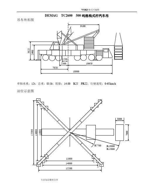
DEMAG TC2600 500吨格构式杆汽车吊吊车外形图单轴承重:12t,总重:83.8t,轮胎:14.00 R25 PR22,行驶速度:0-65km/h 站位示意图主车尺寸转弯半径路基板尺寸:6000×2600,需处理的地域面积:11000×7600,C15毛石(30%掺入)混凝土基础,深度2500。
压力扩散角38.6°,单支腿最大载荷小于300吨。
臂杆组合形式SSL:主臂+超起工作速度(无级变速)吊钩★双钩可分解为单钩。
风速及风压性能表依据的数值:风速:9.8m/s,许用风压:60N/m2,载荷的迎风面积取:1.2m2/t。
使用中不得超过下表的数据:通常按许用风压60N/m2,载荷的迎风面积取:1.0m2/t计算。
风压×面积=风压×面积风速=SQR(风压×1.6)DEMAG TC2600 500吨格构式汽车吊臂杆参数杆型:717-01,支腿范围:15.5×15.5m,配重:148tSH主臂最大支腿载荷305tSH主臂最大支腿载荷301tSH主臂最大支腿载荷333tSH主臂最大支腿载荷TC2600型500吨格构式杆汽车吊轻型主臂起重性能表杆型:717-01,支腿范围:15.5×15.5m,配重:148t以上3表SW主臂+付臂最大支腿载荷300t主臂杆型:717-01,超起支撑杆型:617-01/612-02,超起支撑杆长:30m,超起回转半径15m,超起配重0-250t支腿范围:15.5×15.5m,配重:149t,最大支腿载荷324t主臂杆型:717-01,超起支撑杆型:617-01/612-02,超起支撑杆长:30m,超起回转半径15m,超起配重0-250t支腿范围:15.5×15.5m,配重:149t,最大支腿载荷324t主臂杆型:717-01,超起支撑杆型:617-01/612-02,超起支撑杆长:30m,超起回转半径15m,超起配重0-250t支腿范围:15.5×15.5m,配重:149t,最大支腿载荷324t主臂杆型:717-01,超起支撑杆型:617-01/612-02,超起支撑杆长:30m,超起回转半径15m,超起配重0-250t支腿范围:15.5×15.5m,配重:149t,最大支腿载荷324t主臂杆型:717-01,超起支撑杆型:617-01/612-02,超起支撑杆长:30m,超起回转半径13m,超起配重0-225t支腿范围:14×14m,配重:149t,最大支腿载荷342t主臂杆型:717-01,超起支撑杆型:617-01/612-02,超起支撑杆长:30m,超起回转半径13m,超起配重0-225t支腿范围:14×14m,配重:149t,最大支腿载荷342t主臂杆型:717-01,超起支撑杆型:617-01/612-02,超起支撑杆长:30m,超起回转半径13m,超起配重0-225t支腿范围:14×14m,配重:149t,最大支腿载荷342t主臂杆型:717-01,超起支撑杆型:617-01/612-02,超起支撑杆长:30m,超起回转半径13m,超起配重0-225t支腿范围:14×14m,配重:149t,最大支腿载荷342t超起回转半径13m,超起配重0-225t支腿范围:14×14m,配重:149t,最大支腿载荷342t超起回转半径13m,超起配重0-225t支腿范围:14×14m,配重:149t,最大支腿载荷342t主臂杆型:717-01,超起支撑杆型:617-01/612-02,超起支撑杆长:30m,超起回转半径13m,超起配重0-225t支腿范围:11×11m,配重:129t,最大支腿载荷342t主臂杆型:717-01,超起支撑杆型:617-01/612-02,超起支撑杆长:30m,超起回转半径13m,超起配重0-225t支腿范围:11×11m,配重:129t,最大支腿载荷342t主臂杆型:717-01,超起支撑杆型:617-01/612-02,超起支撑杆长:30m,超起回转半径13m,超起配重0-225t支腿范围:11×11m,配重:129t,最大支腿载荷342t主臂杆型:717-01,超起支撑杆型:617-01/612-02,超起支撑杆长:30m,超起回转半径13m,超起配重0-225t支腿范围:11×11m,配重:129t,最大支腿载荷342t超起回转半径13m,超起配重0-225t支腿范围:11×11m,配重:129t,最大支腿载荷342t超起回转半径13m,超起配重0-225t支腿范围:11×11m,配重:129t,最大支腿载荷342t主臂杆型:717-01,超起支撑杆型:617-01/612-02,超起支撑杆长:30m,付臂杆型:617-01超起回转半径13m,超起配重0-200t支腿范围:14(15.5)×14(15.5)m,配重:149t,最大支腿载荷333t主臂长:42m,主臂角度:85°主臂杆型:717-01,超起支撑杆型:617-01/612-02,超起支撑杆长:30m,付臂杆型:617-01超起回转半径13m,超起配重0-200t支腿范围:14(15.5)×14(15.5)m,配重:149t,最大支腿载荷333t主臂长:42m,主臂角度:85°主臂杆型:717-01,超起支撑杆型:617-01/612-02,超起支撑杆长:30m,付臂杆型:617-01超起回转半径13m,超起配重0-200t支腿范围:14(15.5)×14(15.5)m,配重:149t,最大支腿载荷333t主臂长:48m,主臂角度:85°主臂杆型:717-01,超起支撑杆型:617-01/612-02,超起支撑杆长:30m,付臂杆型:617-01超起回转半径13m,超起配重0-175t支腿范围:14(15.5)×14(15.5)m,配重:149t,最大支腿载荷333t主臂长:54m,主臂角度:85°主臂杆型:717-01,超起支撑杆型:617-01/612-02,超起支撑杆长:30m,付臂杆型:617-01超起回转半径13m,超起配重0-150t支腿范围:14(15.5)×14(15.5)m,配重:149t,最大支腿载荷333t主臂杆型:717-01,超起支撑杆型:617-01/612-02,超起支撑杆长:30m,付臂杆型:617-01超起回转半径13m,超起配重0-100t支腿范围:14(15.5)×14(15.5)m,配重:149t,最大支腿载荷333t主臂杆型:717-01,超起支撑杆型:617-01/612-02,超起支撑杆长:30m,付臂杆型:617-01超起回转半径13m,超起配重0-100t支腿范围:14(15.5)×14(15.5)m,配重:149t,最大支腿载荷333t主臂角度85°主臂杆型:717-01,超起支撑杆型:617-01/612-02,超起支撑杆长:30m,付臂杆型:617-01超起回转半径13m,超起配重0-200t支腿范围:14(15.5)×14(15.5)m,配重:149t,最大支腿载荷318t主臂杆型:717-01,超起支撑杆型:617-01/612-02,超起支撑杆长:30m,付臂杆型:617-01超起回转半径13m,超起配重0-200t支腿范围:14(15.5)×14(15.5)m,配重:149t,最大支腿载荷318t主臂长:48m,主臂角度:75°主臂杆型:717-01,超起支撑杆型:617-01/612-02,超起支撑杆长:30m,付臂杆型:617-01超起回转半径13m,超起配重0-200t支腿范围:14(15.5)×14(15.5)m,配重:149t,最大支腿载荷318t主臂长:54m,主臂角度:75°主臂杆型:717-01,超起支撑杆型:617-01/612-02,超起支撑杆长:30m,付臂杆型:617-01超起回转半径13m,超起配重0-200t支腿范围:14(15.5)×14(15.5)m,配重:149t,最大支腿载荷318t主臂长:60m,主臂角度:75°主臂杆型:717-01,超起支撑杆型:617-01/612-02,超起支撑杆长:30m,付臂杆型:617-01超起回转半径13m,超起配重0-200t支腿范围:14(15.5)×14(15.5)m,配重:149t,最大支腿载荷318t主臂长:66m,主臂角度:75°主臂杆型:717-01,超起支撑杆型:617-01/612-02,超起支撑杆长:30m,付臂杆型:617-01超起回转半径13m,超起配重0-200t支腿范围:14(15.5)×14(15.5)m,配重:149t,最大支腿载荷318t主臂角度:75°。
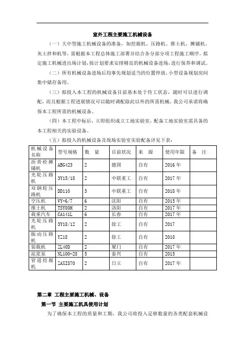
室外工程主要施工机械设备(一)大中型施工机械设备的准备,如挖掘机、压路机、推土机、摊铺机、灰土拌和机等,需根据本工程总体施工部署并结合各分部分项工程施工顺序,拟定施工机械进出场计划,按计划要求安排精良的机械设备进场,进行保养和调试。
(二)所有机械设备进场后均事先规划适当的位置停放,小型设备规划房间集中储存备用。
(三)拟投入本工程的机械设备目前基本处于待工状态,随时可以进行调配,而且根据工程进展情况可以随时调配除此以外的所需机械,我公司承诺将确保本工程所需的机械设备。
(四)本工程中标后,立即组织成立工地实验室,配备工地实验室需具备的本工程相关的实验设备。
(五)拟投入的机械设备及现场实验室实验配备详见下表:第二章工程主要施工机械、设备第一节主要施工机具使用计划为了确保本工程的质量和工期,我公司将投入足够数量的各类配套机械设备。
根据现有装备的数量、质量情况,按照施工计划,分期分批地组织进场。
第三章工程主要施工机械、设备(一)市政管网和道路机械1、施工机械计划表拟投入主要施工机械设备情况表2、计量器具投入表(二)交通标线施工机械、设备施工主要机械设备配置表第四章工程主要施工机械、设备第五章工程主要施工机械、设备第一节设备安全使用的基本制度(一)设备岗位责任制1、大型设备实行机长负责制,中小型设备实行班组长负责制。
2、大型设备必须实行“三定”制度(即定人、定机、定岗),操作人员要相对稳定。
3、设备操作人员要坚守岗位,坚持正确使用设备,按规定进行保养,严格执行安全技术操作规程,确保设备正常运行。
(二)持证上岗制度1、设备操作人员必须经过培训,达到“三好”、“四会”的要求(即管理好、使用好、维修好,会使用、会养修、会检查、会排除简单故障)。
2、特种设备外其他设备操作人员,应由产权单位或生产厂家进行培训,经考试合格后,颁发设备操作证或培训证明。
3、特种设备操作人员操作证必须在有效期内,超过有效期视为无效证件。
(三)交接班制度1、交接班制度由值班司机执行,多人操作的单机或机组除执行岗位交接外,值班负责人或机长应进行全面交接并填写设备运转交接记录。
SCC550C履带起重机
整机基本尺寸
主要技术特点
主要性能参数表
运输尺寸
吊装示意图
设备简介
上车
下车
作业设备
安全装置
工况组合
工况组合
主臂H工况
固定副臂FJ工况
SANY CRAWLER CRANE SCC550C 整机基本尺寸
SANY CRAWLER CRANE SCC550C 运输尺寸主要性能参数表
SANY CRAWLER CRANE SCC550C
长(L) 1.64m 宽(B) 0.65m 高(H) 0.39m 重量 0.7t
运输尺寸
长(L) 3.11m 宽(B) 0.6m 高(H) 0.55m 重量 0.
1t 运输尺寸
SANY CRAWLER CRANE SCC550C
SANY CRAWLER CRANE SCC550C 上车部分
SANY CRAWLER CRANE SCC550C
下车部分
安全装置
工况组合
80°
70°60°
0.9
5
10
15
20
25
30
34
工 作 幅 度 (m)
H工况主臂载荷表
H工况主臂载荷表
H工况主臂载荷表固定副臂FJ工况
FJ工况作业范围图FJ工况副臂载荷表
00.95101520253034
工 作 幅 度 (m)
FJ工况副臂载荷表
FJ工况副臂载荷表
Notes FJ工况副臂载荷表。
三一吊车上车操作方法
三一吊车上车操作方法包括以下几个步骤:
1. 确保吊车的刹车处于锁定状态,并且车身稳定。
2. 检查吊车的工作条件和工作环境是否安全,确认周围没有人员或障碍物。
3. 检查吊车上的控制器和仪表是否正常工作,确保它们处于可用状态。
4. 根据需要,选择适当的梯子或台阶,爬上吊车上部的驾驶室。
5. 确保驾驶室内部干净整洁,没有杂物。
检查座位和脚踏板是否调整到适合您的位置。
6. 确保吊车的所有控制器和开关处于关闭状态。
7. 启动吊车的发动机,并根据需要调整油门、离合器、档位和制动器。
8. 根据需要,调整并确认吊臂、支腿、拉杆、滑轮等部分的位置和工作状态。
9. 根据工作需要打开所需要的功能,如起重机、回转、伸缩、升降等。
10. 控制吊车上的操纵杆或按钮,以实现所需的运动和操作。
根据需要,使用吊车上的仪表监控吊车的工作状态。
11. 注意观察吊车的周围环境,确保安全操作,防止伤害和事故发生。
12. 在完成工作后,关闭吊车上的所有控制器和开关。
将吊车的部件调整到安全的位置。
13. 关闭吊车的发动机,并清理和整理驾驶室,确保它们在离开前处于良好状态。
14. 根据需要,使用适当的梯子或台阶,从吊车上部的驾驶室下来。
这些步骤是一般的三一吊车上车操作方法,具体操作步骤可能因吊车型号和实际工作需求而有所不同。
在操作之前,应仔细阅读吊车的操作手册,并遵守相关的操作规程和安全标准。
8--500吨汽车吊性能参数表8吨汽车起重机性能表 (2)20吨汽车吊机额定性能表 (3)25吨汽车起重机起重性能表(主臂) (4)30吨汽车起重机性能表(一) (6)50吨汽车起重机性能表(主表) (8)80吨汽车起重机起重性能表(一) (10)100t汽车吊性能表 (12)120吨汽车起重机起重性能表 (13)150吨汽车起重机性能表(一) (14)150吨汽车起重机性能表(二) (15)160t汽车吊性能表 (16)200吨汽车吊车 (17)260吨吊车性能表 (18)LTM1300/1-300t全液压汽车吊机 (19)LTM1500-500t全液压汽车吊机 (21)LTM1500-500t全液压汽车吊机 (22)8吨汽车起重机性能表主要技术参数 6.95m吊臂8.50m吊臂10.15m吊臂11.70m吊臂参数名称参数工作半径(m)起升高度(m)起重量(t)工作半径(m)起升高度(m)起重量(t)工作半径(m)起升高度(m)起重量(t)工作半径(m)起升高度(m)起重量(t)全车总重15.50t 3.27.5 8.0 3.49.2 6.7 4.210.6 4.2 4.912.0 3.2 最大爬坡能力22% 3.77.1 5.4 4.08.8 4.5 5.010.1 3.1 5.811.4 2.4 吊臂最大仰角 4.3 6.5 4.0 4.78.3 3.4 5.79.6 2.5 6.710.8 1.9 吊臂全伸时长度11.70m 4.9 5.7 3.2 5.47.6 2.7 6.68.8 1.9 7.79.9 1.4 吊臂全缩时长度 6.95m 5.5 4.6 2.6 6.2 6.8 2.2 7.57.7 1.5 8.88.6 1.0 最大提升高度12.00m 6.9 5.6 1.8 8.4 6.3 1.2 9.77.0 0.9 最小工作半径 3.20m 7.5 4.2 1.5 9.0 4.8 1.0 10.5 5.2 0.8 最小转弯半径9.20m20吨汽车吊机额定性能表以下工况仅供参考,实际请与本公司业务员联系!25吨汽车起重机起重性能表(主臂)以下工况仅供参考,实际请与本公司业务员联系!(注:本表内红字及红字以上栏目的数字为吊臂强度所决定,其下面栏目数字为倾翻力矩决定)25吨汽车起重机起重性能表(副臂)30吨汽车起重机性能表(一)以下工况仅供参考,实际请与本公司业务员联系!主要技术参数主臂起重性能工作半径(m)支腿全伸不用支腿名称参数10.00m17.00m24.00m31.00m10.00m 全车总重32.2t 3.0030.00 20.00 8.00 最大爬坡能力31% 3.3530.00 20.00 7.00 最大提升高度34.00m 3.5028.10 20.00 6.40 吊臂全伸时长度31.00m 4.0024.20 20.00 5.10 吊臂全缩时长度10.00m 4.5021.40 20.00 13.00 4.20 最小转弯半径11.50m 4.820.00 20.00 13.00 3.70 最大仰角80° 5.019.20 19.20 13.00 3.40 30t吊钩重0.35t 5.517.50 17.50 13.00 2.80 12t吊钩重0.20t 6.016.00 16.00 13.00 2.30 4t吊钩重0.10t 6.514.60 14.60 13.00 9.00 1.90 10m吊臂时钢丝绳数8根7.013.50 13.50 12.00 9.00 1.60 10-17m时钢丝绳数5根7.512.00 12.00 11.20 9.00 1.30 24m时钢丝绳数4根8.010.50 10.50 10.50 9.00 1.00 31m时钢丝绳数3根8.59.40 9.40 9.009.87.20 7.20 7.7010.0 6.95 6.95 7.5011.0 5.80 5.80 6.4012.0 4.90 4.90 5.5514.0 3.45 3.45 4.2016.0 2.50 3.2018.0 1.80 2.4520.0 1.30 1.9022.00.85 1.5024.0 1.1026.00.7527.00.65(注:本表内红字及红字以上栏目的数字为吊臂强度所决定,其下面栏目数字为倾翻力矩决定)30吨汽车起重机性能表(二)吊臂角度工作半径使用8.45m 副臂倾角5°吊臂角度工作半径使用13.5m副臂倾角5°80°7.9 4.00 80°9.3 2.5078.5°9.5 4.00 77°12.0 2.5078°10.2 3.80 76°12.7 2.35 76°11.2 3.30 74°14.1 2.10 74°12.2 2.90 72°15.6 1.95 72°13.4 2.70 70°17.1 1.80 70°14.6 2.50 68°18.5 1.65 68°16.0 2.35 66°19.9 1.50 66°17.3 2.20 64°21.3 1.40 64°18.5 2.10 62°22.7 1.30 62°19.8 2.05 60°24.0 1.20 60°20.7 1.85 58°25.3 1.15 58°21.9 1.65 55°27.1 1.05 55°23.6 1.30 54°27.70.95 54°24.1 1.15 52°28.80.80 52°25.00.95 50°29.90.65 50°25.80.75 48°30.90.55 48°26.80.60注:1、若副臂在工作位置,但仍用主臂吊装,主臂的起重性能应相应的减去1.4t2、使用副臂吊装时,主臂的角度不得大于45,否则将倾翻50吨汽车起重机性能表(主表)以下工况仅供参考,实际请与本公司业务员联系!不支第五支腿,吊臂位于起重机前方或后方;支起第五支腿,吊臂位于侧方、后方、前方工作半径(m)主臂长度(m)10.7018.0025.4032.7540.103.050.003.543.004.038.004.534.005.030.0024.705.528.0023.506.024.00 22.20 16.306.521.0020.0015.007.018.50 18.00 14.10 10.208.014.5014.0012.409.207.509.011.50 11.20 11.10 8.30 6.5010.09.2010.007.50 6.0012.0 6.40 7.50 6.80 5.2014.0 5.10 5.70 4.6016.0 4.00 4.70 3.9018.0 3.10 3.70 3.3020.0 2.20 2.90 2.9022.0 1.60 2.30 2.4024.0 1.80 2.0026.0 1.40 1.5028.0 1.2030.00.90各臂伸缩率(%)二0 100 100 100 100 三0 0 33 66 100 四0 0 33 66 100 五0 0 33 66 100钢丝绳倍率12 8 5 4 3吊钩重量0.515 0.215 (注:本表内红字及红字以上栏目的数字为吊臂强度所决定,其下面栏目数字为倾翻力矩决定)50吨汽车起重机性能表(副臂)吊臂位于起重机侧方或后方主臂仰角(°)吊臂长度(m)40.10+5.10主臂+副臂40.10+9.00主臂+副臂40.10+16.10主臂+副臂0°20°0°20°0°20°78 4.0 3.6 3.2 1.9 1.5 0.8 75 3.8 3.2 3.0 1.8 1.30.8 72 3.2 2.9 2.8 1.7 1.2 0.7 70 3.0 2.5 2.5 1.6 1.20.6 65 2.5 2.0 2.0 1.4 1.1 0.5 60 1.9 1.6 1.5 1.00.80.5 55 1.4 0.8 1.0 0.6 0.6 0.4各节臂伸缩率(%) 二100 三四五钢丝绳倍率 1 吊钩重量0.180吨汽车起重机起重性能表(一)以下工况仅供参考,实际请与本公司业务员联系!主臂起重性能表工作半径(m)吊臂长度(支腿全伸)吊臂长度(不伸支腿) 12.0m18.0m24.0m30.0m36.0m40.0m44.0m12.0m2.580.0 45.0 15.03.080.045.035.015.03.580.0 45.0 35.0 15.04.070.045.035.011.74.562.0 45.0 35.0 27.0 9.55.056.040.032.027.08.05.550.0 37.0 29.2 27.0 22.06.86.045.034.327.225.022.0 5.86.539.4 31.5 25.3 23.2 22.0 18.0 5.07.035.629.123.721.520.318.0 4.38.027.8 25.4 21.0 18.8 17.7 15.7 12.0 3.29.520.820.817.815.714.613.212.0 2.010.019.2 19.2 17.0 15.0 13.8 12.6 11.4 1.711.016.515.613.512.411.410.411.814.7 14.7 12.6 11.4 10.6 9.712.014.214.212.411.210.49.513.012.5 12.5 11.3 10.2 9.3 8.814.610.010.010.09.08.57.815.09.4 9.4 9.4 8.7 8.2 7.616.08.18.18.17.77.117.8 6.2 6.2 6.2 6.8 6.320.0 4.5 4.5 4.5 5.1 5.622.0 3.4 3.4 4.0 4.423.0 3.0 3.0 3.5 3.926.0 1.7 2.2 2.627.0 1.9 2.228.0 1.6 1.930.0 1.0 1.331.0 1.180吨汽车起重机起重性能表(二)主要技术参数副臂起重性能主臂仰角支腿全伸在两侧或后部吊装名称参数44m 主臂+9.5m 副臂5°夹角 44m 主臂+15m 副臂5°夹角 工作半径(m)起重性能(t)工作半径(m)起重性能(t)全车总重 63.00t 81.3° 10.0 6.00 11.5 4.00 主臂全伸时长度 44.00m 80.4°11.06.0012.64.00主臂全缩时长度 12.00m 80.1° 11.3 5.90 13.0 4.00 最大仰角 82° 78.6° 13.0 5.20 14.6 3.75 最大爬坡能力 16%75.2°16.04.4018.23.05最小转弯半径 15.40% 70.8° 20.0 3.60 22.5 2.55最大提升高度58.50m 66.0°24.0 3.00 27.2 2.10 80t 主吊钩重 1t 63.8° 26.0 2.75 29.1 2.05 80t 辅助吊钩重0.5t58.0° 30.3 1.50 34.01.206t 副吊钩重 0.25t 55.4°32.01.20100t汽车吊性能表120吨汽车起重机起重性能表以下工况仅供参考,实际请与本公司业务员联系!工作半径(m)主臂长度(m)12.612.616.620.624.528.532.536.540.544.548.552.556.03120 1113.510710292495 94 88 81 694.586827566579 76 70 62 516666662554940756 56 55 49 44.5 38 32 23.6848.54847444038.53222.120.1942 41.5 40.5 40 36.5 32.5 29.8 21.3 19.9 15.8103736.535.535.533.530.527.921.319.715.814.912.6 1229.1 28 28.9 27.8 26.2 24.5 21.3 18.7 15.8 14.5 11.8 1424.822.723.522.522.521.618.916.81513.311.1 1618.3 19.4 18.4 19 19.1 16.9 15.1 13.6 12.2 10.3 1815.815.815.216.816.31513.512.311.19.6 2013.2 13.8 14.1 14.2 13.4 12.2 11.1 10.2 8.9 2211.512.412.212.111.710.910.19.48.3 2410.7 10.5 10.4 10 9.9 9.2 8.6 7.7 269.39.298.58.68.387.2 288 8 7.3 7.4 7.6 7.4 6.7 3077.2 6.5 6.3 6.5 6.9 6.3 32 6.3 6 5.6 6 6.1 5.8 34 5.5 5.6 5.2 5.6 5.3 5.2 36 5.1 4.8 5.1 4.5 4.5 38 4.7 4.5 4.44 3.9 40 4.2 4 3.5 3.7 42 3.9 3.6 3.2 3.5 44 3.2 2.8 2.7 46 2.6 2.4 2.7 48 2 2 50 1.7 1.7 52 1.4 54 1.2150吨汽车起重机性能表(一)以下工况仅供参考,实际请与本公司业务员联系!(注:本表内红字及红字以上栏目的数字为吊臂强度所决定,其下面栏目数字为倾翻力矩决定)150吨汽车起重机性能表(二)吊臂回转至后部及两侧时吊装性能工作半径(m)吊臂长度 (m)13.917.721.325.028.732.336.039.643.152.83.0 140.03.6 131.3 65.9 64.44.0 122.6 65.0 63.74.5 109.2 65.0 63.7 56.65.0 100.2 64.9 61.2 55.46.0 80.3 64.9 56.5 51.7 46.6 41.27.0 68.9 62.0 52.5 47.2 43.9 37.8 33.1 31.58.0 58.7 57.1 48.1 44.6 39.0 34.4 31.9 30.39.0 49.5 49.3 44.8 40.9 35.8 31.9 29.5 27.1 27.510.0 43.041.9 41.6 35.6 33.4 29.6 27.4 25.3 24.912.0 31.9 31.9 31.3 27.7 24.6 22.6 22.0 21.3 17.6 14.0 24.624.6 24.6 24.6 21.4 20.3 19.3 18.2 15.9 16.0 18.518.518.518.4 17.5 16.8 15.4 13.7 18.0 14.7 14.7 14.7 14.714.7 14.4 12.5 12.0 20.0 11.8 11.8 11.8 11.811.8 11.4 10.6 23.0 8.5 8.5 8.5 8.58.59.0 26.0 6.2 6.2 6.2 6.2 6.2 7.6 29.0 4.4 4.3 4.2 4.2 6.1 32.0 2.9 2.9 2.1 4.3 35.0 1.7 1.7 2.8 38.0 0.3 2.0 41.0 1.2 44.0 1.0(注:本表内红字及红字以上栏目的数字为吊臂强度所决定,其下面栏目数字为倾翻力矩决定)160t汽车吊性能表200吨汽车吊车260吨吊车性能表LTM1300/1-300t全液压汽车吊机LTM1300/1-300t全液压汽车吊机主臂额定性能表:支腿开距=8.85×8.5m、旋转角度=360°、标准配重=87.5t。

SUPERSTRUCTURE SPECIFICATIONSCAB AND CONTROLSBy 4 control levers for swing, boom hoist, main winch, boom tele-scoping or auxiliary winch with 2 control pedals for boom hoist,boom telescoping based on ISO standard layout.Control lever stands can change neutral positions and tilt for easyaccess to cab.One sided one-man type, steel construction with sliding door ac-cess and tinted safety glass windows opening at side.Operator's 3 way adjustable seat with headrest and armrest.OUTRIGGERHydraulically operated H-type outriggers. Each outrigger control-led simultaneously or independently from either side of carrier.Equipped with sight level gauge. Floats mounted integrally withthe jacks retract to within vehicle width. All cylinders fitted with pi-lot check valves.Crane operation with different extended length of each outrigger.Equipped with extension width detector for each outrigger.Extended widthFully.................................6,800 mmMiddle..............................4,600 mmMinimum..........................2,390 mmFloat size (Diameter).......400 mmFRONT JACKA fifth hydraulically operated outrigger jack. Mounted to the frontframe of carrier to permit 360o lifting capabilities.Hydraulic cylinder fitted with pilot check valve.Equipped with front jack extension detector.Float size(Diameter)...........350 mmCOUNTERWEIGHTIntegral with swing frameMass................................4,200 kgTADANO Automatic Moment LimiterMain unit in crane cab gives audible and visual warning of ap-proach to overload. Automatically cuts out crane motions beforeoverload. With working range (load radius and / or boom angleand / or tip height and / or swing range) limit function.Nine functions are constantly displayed.Either moment as percentage or main hydraulic pressureEither boom angle or moment %Either boom length or potential hook heightEither actual load radius or swing angleActual hook loadPermissible loadEither jib offset angle or number of parts of line of ropeBoom position indicatorOutrigger position indicatorNOTEEach crane motion speed is based on unladen conditions. BOOM5-section full power partially synchronized telescoping boom ofhexagonal box construction with 6 sheaves at boom head. Thesynchronization system consists of 2 telescope cylinders, exten-sion cables and retraction cables. Hydraulic cylinders fitted withholding valves. Selection of 2 boom telescoping modes.Fully retracted length.......11.1 mFully extended length.....42.0 mExtension speed..............30.9 m in 123 sJIB2-staged boom extension type. Triple offset (5o /25o / 45o ) type.Stored under base boom section.Single sheave at jib head.Length............................9.0 m and 14.6 mSINGLE TOP( Auxiliary boom sheave )Single sheave. Mounted to main boom head for single line work.ELEVATIONBy a double-acting hydraulic cylinder, fitted with holding valve.Automatic Speed Reduction and Soft Stop function.Elevation speed...............- 2o to 80o in 68 sHOIST-Main winchVariable speed type with grooved drum driven by hydraulic axialpiston motor through winch speed reducer. Power load loweringand hoisting. Equipped with automatic brake (Neutral brake) andcounterbalance valve.Controlled independently of auxiliary winch.Single line pull.................42.2 kN { 4,300kgf }Single line speed.............143 m/min (at the 4th layer)Wire rope.........................Spin-resistant typeDiameter..........................19.05 mmLength.............................227 mHOIST-Auxiliary winchVariable speed type with grooved drum driven by hydraulic axialpiston motor through winch speed reducer. Power load loweringand hoisting. Equipped with automatic brake (Neutral brake) andcounterbalance valve.Controlled independently of main winch.Single line pull.................44.1 kN { 4,500kgf }Single line speed.............123 m/min (at the 2nd layer)Wire rope.........................Spin-resistant typeDiameter..........................19.05 mmLength.............................127 mSWINGHydraulic axial piston motor driven through planetary speed reduc-er. Continuous 360o full circle swing on ball bearing slew ring. Au-tomatic Speed Reduction and Soft Stop function.Equipped with manually locked/released swing brake.Swing speed....................1.9 min-1 { rpm }HYDRAULIC SYSTEMPumps.............................Quadruple gear pumps driven bycarrier engine through P.T.O.Control valves..................Multiple valves actuated by pilotpressure with integral pressure reliefvalves.Circuit..............................Equipped with air cooled type oilcooler. Oil pressure appears on AMLdisplay for main circuit.Oil tank capacity..............approx. 690 litersFilters...............................Return line filterCARRIER SPECIFICATIONS and EQUIPMENTEQUIPMENTFor superstructureStandard Equipment4.5 ton capacity, hook ball and swivelControl pedals for boom hoist, boom telescoping3 working lightsExternal lamp(AML)Cable followerSun visorOptional Equipment55 ton capacity, 6 sheaves hook block20 ton capacity, 2 sheaves hook blockWinch drum rotation indicator(Visual)Winch drum mirror(Hoist mirror)Sun shadeSun visorElectric fanHot water heater and air conditionigCab floor matFor carrierStandard EquipmentFan clutch :Viscous-typeIntake air heaterOverheating warning buzzerCooling water level warning buzzerEngine over-run alarmPTO hour meterSeat belt :3 point type for driverTilting-telescoping steering wheelWindshield wiper(with intermittent wiping)and washerWindow glass :Tinted, Infrared and Ultraviolet rays absorptionTachometerLow air pressure warning buzzerAM radioCar heater(Hot water type)with defrosterThird differential gear lockSpeedometer(with odometer)Sun visorSpare tire carrier with lock keyTool box with lock keyFuel tank cap with lock keyBack-up lightBack-up alarmAir filter warning light(Instrument cluster)Towing hook(Front and rear, Eye type)AshtrayCigarette lighterFront fog lampOwner's tool setCab floor matOptional EquipmentCar cooler(Refrigerant:R134a)AM/FM radioMANUFACTURERNISSAN DIESEL MOTOR Co., LTD.MODELKG48UXN ( Right hand steering, 8 x 4 )ENGINE [ EURO-2 ]Model NISSAN PF6TBType 4 cycle, turbo charged, 6 cylinder inline,direct injection, water cooled diesel en-gine.Piston displacement12,503 cm3Bore x stroke133 mm x 150 mmMax. output (JIS)257 kW{350PS/345hp} at 2100 min-1{rpm}Max. torque (JIS)1460 Nm{150 kgfm} at 1200 min-1{rpm}TRANSMISSION7 forward and 1 reverse speeds, synchromesh on 2nd - 7th gear andconstant-mesh on 1st and reverse gear.AXLESFront...........................Reverse - elliot typeRear............................Full floating type.SUSPENSIONFront...........................Leaf spring.Rear............................Full floating type.STEERINGRecirculating ball screw type with linkage power assistance.BRAKE SYSTEMService........................Full air brake with maltiprotection valveand auto slack adjuster on all wheels, du-al air line system, internal expanding lead-ing and trailing shoe type.Parking........................Mechanically operated by hand brake lev-er, internal expanding duo-servo shoetype acting on drum at transmission caserear.Auxiliary.......................Electro-pneumatic operated exhaustbrake.Emergency..................Pneumatically controlled spring brake, act-ing on all rear axles.TIRESFront...........................315/80 R 22.5 156/150, Single x 4Rear............................315/80 R 22.5 156/150, Dual x 4Spare..........................315/80 R 22.5 156/150, Single x 1ELECTRONIC SYSTEM24 V DC. 2 batteries of 12 V (JIS)115F51, 96Ah at 5-hour rateAlternator 24V-50AFUEL TANK CAPACITY300 litersL I F T I N G H E I G H T (m )5101520253035404550556065051015202530354070o50o40o11.1 m Boom5o25o15.0 m Boom 18.8 m Boom 34.3 m Boom42.0 m Boom9.0 m Jib30o10o0o14.6 m Jib60o80o26.6 m Boom45o20oRADIUS (m)Telescoping modeI42.0 m Boom 34.3 m Boom 26.6 m Boom 18.8 m Boom 15.0 m Boom Boom LengthNOTE:1. Boom and jib geometry shown are for unloaded condition and machine standing level on firm supporting surface.Boom deflection and subsequent radius and boom angle change must be accounted for when applying load to hook.o14.6 m Jib9.0 m Jib42.0 m Boom 38.1 m Boom 34.3 m Boom26.6 m Boom18.8 m Boom11.1 m Boom0510152025303540RADIUS (m)5101520253035404550556065L I F T I N G H E I G H T (m )5o25o45o80o70o60o50o40o30o20o10ooTelescoping mode II42.0 m Boom 38.1 m Boom 34.3 m Boom 26.6 m Boom 18.8 m Boom Boom LengthNOTE:1. Boom and jib geometry shown are for unloaded condition and machine standing level on firm supporting surface.Boom deflection and subsequent radius and boom angle change must be accounted for when applying load to hook.Load3.011.1 m15.0 m42.0 m38.1 mTelescoping III050100100010005010040,000 28,000radius (m)boomboom boom20,000Outriggers fully extended 6.8m55,00034.3 m boomboom26.6 m boom18.8 m boom40,000 28,0003.5 20,00043,70038,500 20,0004.0 28,00038,10033,800 28,0004.5 19,80034,20030,800 19,0005.0 28,00030,40027,400 27,2005.5 18,20027,80025,400 17,5006.0 24,70025,00022,800 22,5006.5 16,80023,20021,400 16,2007.0 20,70021,00019,300 19,1007.5 15,70019,70018,300 15,2008.0 17,60017,90014,600 14,2009.0 14,30015,20013,50010.0 11,30011,6009,500 9,10011.0 11,4009,60012.0 7,5007,8005,10014.0 7,2005,50016.0 3,50018.020.022.024.026.028.030.032.034.0ModeI I II III III II1,2001,7002,4003,3004,5006,2008,60010,30012,50014,20015,80016,70017,80018,90020,00020,00020,00020,0005,40012,00011,4002,40012,8003,00013,6007,8003,7007,20014,0004,7009,30014,0008,50010,80010,2006,2003,0009,6008,8002,20014,0003,9005,1001,60011,30013,50010,40014,00013,00012,5006,8003,2006,4005,8002,8008,0003,6004,2002,5007,6008,0007,0008,0008,0008,0004,9003,6006,9006,4002,8004,1004,7002,2008,0008,0007,5008,0008,0005,5003,2007,5006,9002,5004,2005,2001,9008,0008,0008,0008,0008,0005,9001,2005008002,1001,1001,4001,7001,8007001,0001,4001,4004507001,000500UNIT : kg •@CLASS OF CRANE ; C32nd boom3rd boom4th boomTop boom0003333666610010010003303366661001001000330336666100100100Telescoping conditions(%)I, II I, IINOTES1. Rated lifting capacities shown in the table are based on the condition that the crane is set on firm ground horizontally. Those above bold line are based on crane strength and those below, it is stability.2. Rated lifting capacities in the stability area comply with part 2 / ISO 4305.3. The mass of load handling devices such as hook blocks {570 kg for *55 ton capacity, 400 kg for *20 ton capacity and 130 kg for4.5 ton capacity} and slings, shall be considered part of the load and must be deducted from rated lifting capacities.4. Without front jack extended, when the boom is within the Over-front, Rated lifting capacities are different from those for the boom in the Over-side and Over-rear.5. Standard number of parts of line for each boom length is as shown below. Load per-line should not surpass 42.2 kN {4,300 kgf} for main winch rope and 44.1 kN {4,500 kgf} for auxiliary winch rope.*: OptionalBoom Length11.1 m15.0 m18.8 m26.6 m34.3 m38.1 m42.0 m Jib/Single topNumber of parts of line**13/1210754441**: With single top (When the lifting capacities is 55,000 kg)6. Special weather caution: Refer to the operation and maintenance manual.7. For rated lifting capacity of single top, subtract the main hook mass from the relevant boom rated lifting capacity. Rated lifting capacity of single top should not exceed 4,500 kg.8. Load radius shown in the table includes the deflection of the boom. Therefore, perform it according to the load radius. However for the jib3.005010001000100050100 LoadTelescoping I III III III III, II I, II15.0 m42.0 m38.1 mLoad15.0 m11,1004,3009,40013,50013,30016,4002,9003,50014,0002,10020,0005,10020,0003,8008,0006,80012,70018.01,50016.0 1,10028,0006,70014,0001,90014.011,1001,30028,0001,00012.0 3,0005,3003,80011.012,0001,8002,1003,000 2,70010.0 4,8004,700 6,1009.0 3,9004,2005,900 5,5008.0 7,9006,4007,500 9,1007.5 6,6007,0008,300 8,0007.0 10,5008,90010,600 12,3006.5 9,60010,00012,200 11,80020,0006.0 14,60012,80015,800 17,7005.5 14,60015,10019,200 18,7005.0 18,90020,20026,300 19,7004.5 24,90025,50028,000 28,0004.0 20,00032,00032,000Outriggers extended to middle 4.6 m20,00032,0003.5 28,0001,00028,0009,7008,5002,3003,5002,70014,0005,80010,1004,50011,9008,7007,5001,6004,6003,8008,0001,2001,8007,1008,0005,6008,0008,0008,0002,6004,2003,4001,4006,5008,0005,2008,0008,0002,2003,8003,0001,0006,1008,0004,8008,0007,9001,900UNIT : kg CLASS OF CRANE ; C3033033666610010010003303366661001001000330336666100100100radius (m)Mode2nd boom3rd boom4th boomTop boomTelescoping conditions(%)boomboom boom11.1 m34.3 m boomboom26.6 m boom18.8 m boomradius (m)boomboom11.1 m26.6 m boom18.8 m boom10,400050100010003.0Telescoping conditions(%)Telescoping I III IIII, II5,1002,1004,3008,8006,1007,3001,60010,4008,8002,10010,8001,4003,6003,0007,60022,1003,40012,5005,70021,7001,1002,7001,6006,5002,2001,800 2,9001,1001,4002,300 2,000 3,9002,7003,300 4,5002,6002,9003,500 3,200 5,2004,0004,800 6,0004,0004,3005,300 5,00020,0007,0005,7006,900 8,3006,1006,5007,900 7,600 9,8008,40011,9009,5009,90012,500 12,100 14,60013,10016,900Outriggers extended to minimum 2.39 m18,60022,80015,90016,3005,0004,4000330336603303366UNIT : kg •@CLASS OF CRANE ; C33.54.04.55.05.56.06.57.07.58.09.010.011.012.0Mode2nd boom3rd boom4th boom73o80o75o78o77o79o76oB oomangle53o55o58o60o63o65o68o70o5o offset3,5003,5003,5003,4003,2503,1002,8402,4302,2001,9501,7801,3501,05068047025o offset4105909201,1801,4501,5801,7301,8502,0202,1602,2402,3002,3002,3001,3001,3001,3001,2801,2601,2401,2001,1501,1201,0701,0301,00085055045o offset2,3501,8902,1002,2202,5008001,0801,2201,3301,5001,6402,5002,5005005o offset1,1701,0701,1201,1401,2007508008509109501,0001,2001,20048025o offset69065067068070056057058059062063070070042045o offset9.0 m jib14.6 m jib42.0 m boom2,300Outriggers fully extended 6.8 m50o3,5003,5003,5003,4003,2503,1002,8402,4302,2001,9501,7801,5501,3801,1508401,0801,2001,2801,4501,5801,7301,8502,0202,1602,2402,3002,3002,3001,3001,3001,3001,2801,2601,2401,2001,1501,1201,0701,0301,0009809402,3501,8902,1002,2202,5001,0001,0801,2201,3301,5001,6402,5002,5008901,1701,0701,1201,1401,2007708008509109501,0001,2001,2007306906506706807005605705805906206307007005502,30038.1 m boom ( telescoping mode II ) or less than that1,000 5407108209201,000UNIT : kg CLASS OF CRANE ; C3BoomangleOutriggers fully extended 6.8 m1,000 920 8201,000Outriggers fully exended 6.8 m7102,3005507007006306205905805705607006806706506907301,2001,2001,0009509108508007701,2001,1401,1201,0701,1708902,5002,5001,6401,5001,3301,2201,0801,0002,5002,2202,1001,8902,3509409801,0001,0301,0701,1201,1501,2001,2401,2601,2801,3001,3001,3002,3002,3002,3002,2402,1602,0201,8501,7301,5801,4501,2801,2001,080540 8401,1501,3801,5501,7801,9502,2002,4302,8403,1003,2503,4003,5003,5003,50034.3 m boom ( telescoping mode I ) or less than thatUNIT : kg CLASS OF CRANE ; C3 5o offset25o offset45o offset5o offset25o offset45o offset9.0 m jib14.6 m jib73o80o75o78o77o79o76o53o55o58o60o63o65o68o70oUNIT : kg CLASS OF CRANE ; C3Boomangle9.0 m jib14.6 m jib5o offset25o offset45o offset5o offset25o offset45o offset 50o73o80o75o78o77o79o76o53o55o58o60o63o65o68o70o80o73o75o78o77o79o76oBoomangle5o offset3,5003,5003,0802,5502,0901,7001,07025o offset1,3001,5802,3002,3002,2801,3001,3001,3001,2801,2601,07045o offset2,1901,4701,8002,5002,5002,5005o offset1,1701,0101,1401,2001,2001,20025o offset69067068070070070045o offset9.0 m jib14.6 m jib42.0 m boom1,910Outriggers extended to middle 4.6 m3,5003,5003,5003,4002,9102,4801,7801,9002,2002,3002,3002,3001,3001,3001,3001,2801,2601,2402,3502,1002,2202,5002,5002,5001,1701,1201,1401,2001,2001,20069067068070070070038.1 m boom ( telescoping mode II ) or less than that2,3001,01070o6501,0701,5201,1601,3902,30034.3 m boom ( telescoping mode I ) or less than that7007006907006706801,2001,2001,2001,1401,1201,1702,5002,5002,5002,2202,1002,3501,2401,2601,2801,3001,3001,3002,3002,3002,3002,2001,9001,7802,4802,9103,4003,5003,5003,5001,390 1,160 1,520 1,070 650 1,010UNIT : kg CLASS OF CRANE ; C3UNIT : kg CLASS OF CRANE ; C3Outriggers extended to middle 4.6 m9.0 m jib14.6 m jib5o offset25o offset45o offset5o offset25o offset45o offset 80o73o75o78o77o79o76oBoomangleUNIT : kg CLASS OF CRANE ; C3Outriggers extended to middle 4.6 m9.0 m jib14.6 m jibBoomangle70o80o73o75o78o77o79o76o5o offset25o offset45o offset5o offset25o offset45o offsetWORKING AREAFrontD C1. Applicable rated lifting capacities change as the ranges of the working area, depending on the outrigger extension width and whether the front jack is used.2. When the swing automatic stop cancel switch is canceled, the swing does not automatically stop even if the crane becomes overloaded.A:Over-front areaB:Over-rear areaC :Over-side area (right)D:Over-side area (left)E:Rated lifting capacity (capacity with outriggers atminimum extension)F:Rated lifting capacity (capacity with outriggers at middleextension)G:Rated lifting capacity (capacity with outriggers at fullextension)H:Minimum extension width of outriggersI:Middle extension width of outriggersJ:Full extension width of outriggersK:Position of outrigger jack with the beam not extendedL:Position of outrigger jack with the beam extendedhalfwayM:Position of outrigger jack with the beam extended fullyN:Front jackFront jack extendedFL outrigger extended to fully, FR outrigger extended to fullyRL outrigger extended to middle, RR outrigger extended to fullyFront jack not extendedFL outrigger extended to fully, FR outrigger extended to minimumRL outrigger extended to middle, RR outrigger extended to minimum ReferenceMEMO-- 11 --Printed in Japan-- 12 --TADANO LTD. (International Headquarters)4-12, Kamezawa 2-chome, Sumida-ku, Tokyo 130-0014, Japan Tel : +81-(0)3-3621-7752 Fax : +81-(0)3-3621-7785 URL http://www.tadano.co.jp/indexe.htm **********************.jp Specifications are subject to change without notice.。
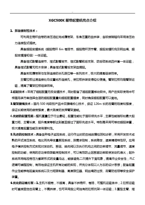
XGC500K履带起重机亮点介绍1.拆装便利性技术:可利用主桅杆自带的液压油缸完成履带架、车身压重的自拆装;各铰接销轴均采用液压动力连接型式插拔。
具备超起变幅系统(超起桅杆6m卷扬节、超起桅杆顶节臂、超起变幅机构及钢丝绳、超起变幅滑轮组) 一体运输。
具备塔式副臂连接节、塔式副臂底节、塔式副臂前后支架、防后倾系统四件套一体运输;具备塔式副臂无枕木安装;具备塔式副臂后支架自提起。
具备实现履带架与车架连接的半孔限位等一系列技术,极大的提高组装效率。
主臂拉板过渡连接处均设置桃形连接孔,使拉板拆装变得轻松便捷。
臂架拉板均随臂架运输,提高了臂架拉板组装效率。
2.超起技术:采用了超起配重无极变幅技术,同时配备了超起配重移动软件。
用户在实际使用中可根据吊装方案选择合适的超起配重量和超起配重幅度,同时确保超起配重可以离地。
3.臂架腰绳技术:国内500吨级别产品中双腰绳核心技术,保证126m长的吊臂的刚度和强度,保证长期使用的疲劳强度,最大限度的发挥臂架潜能。
4.优越的起重性能:整机重量位于行业最轻,起重性能处于国际领先水平,主要性能指标如最大起重力矩、主臂长度、起升高度等都达到甚至超过了国际先进水平。
特别是采用可移动超起装置,极大提高起重性能及使用便利性。
5.先进的控制技术:具备各种电子监控系统,运行作业时的在线故障检测和诊断;采用开发技术成熟的开式液压系统、电比例先导变量泵控系统,按需求控制,系统稳定,速度精调特性好。
应用电子模块控制方式实现对发动机、泵组、换向阀以及执行机构之间的功率调节、流量调节、速度控制的功能;使用的总功率极限载荷控制技术,可以有效防止因泵超功率致使发动机熄火;起升系统采用电控带压力截断形式的变量马达,能够避免二次提升下滑现象,提高作业安全性;PLC 逻辑可编程控制,有效地保证主机所有功能的实现,并充分体现以人为本的设计思想;配备起重作业性能表电脑查询系统以及力矩限制器、高度限位器、钢丝绳防过放、吊臂防后倾等安全保护装置。
第三篇载荷表目录1.概述 (3)1.1 载荷表计算条件 (3)1.2 载荷计算 (3)1.3 倍率选配表 (4)1.4 工作半径 (4)1.5 作业条件 (4)2.载荷表 (5)2.1 主臂工况(H) (5)2.2 安装加长臂时的主臂载荷表(HHC) (7)2.3 安装副臂时的主臂载荷表(HFJ) (9)2.4 固定副臂工况(FJ) (12)2.5 加长臂载荷表(HC) (14)3.操作范围示意图 (15)4.行走说明 (15)4.1起重机带负荷在水平或有坡度路面上行走 (15)4.2起重机无负荷在水平或有坡度的路面上行走 (15)稳定性的确定》。
SCC500C图表中所示额定载荷是在水平坚硬土壤地面、重物被缓慢平稳吊起、非行走吊重工作时的值,而额定载荷总是在倾翻载荷的75%以内。
1.2 载荷计算额定载荷包括起重钩、吊具及缠绕在吊钩到臂头上的钢丝绳的重量。
对于载荷表,实际起重量必须扣除吊钩、吊具及缠绕在主钩到臂头上的钢丝绳的重量(按2kg/m计算)。
吊钩重量表:吊钩5t 15t 30t 50t重量(t) 0.2 0.4 0.5 0.61.3 倍率选配表额定起重量的最大值(t)吊钩吨位1倍率2倍率3倍率4倍率5倍率6倍率7倍率8倍率9倍率5t 515t 5.7 11.4 15.030t 5.7 11.4 17.1 22.8 28.5 3050t 5.7 11.4 17.1 22.8 28.5 34.2 39.9 44.8 50 1.4 工作半径工作半径是指从吊车的回转中心到自由悬挂的载荷钢丝绳或载荷滑轮组的中心的水平距离。
吊臂角度是指吊臂中心线与水平线之间的角度。
在任何情况下操作半径决定起重能力。
1.5 作业条件起重机作业时,与其接触的地面不平度应控制在2°范围内,如果地面不平度超标,必须降负荷使用。
另外,在风速13.8m/s范围内允许操作起重机,场地要有足够的承压能力,在必要的工作范围内无障碍物。
SCC4000型履带式起重机性能参数上海三一科技有限公司液压履带起重机技术协议SCC4000型履带式起重机履带起重机主要外形尺寸、运输尺寸及典型工况载荷表外形尺寸、运输参数第1 页共36 页 1 附件三、SCC40001)SCC4000上海三一科技有限公司液压履带起重机技术协议第4 页共36 页中央配重挂钩×2 长宽高重量327kg后配重托架×1 长宽高重量14756kg10t配重块×36 长宽高重量10000kg超起配重架×1 长宽高重量5616kg第6 页共36 页 6上海三一科技有限公司液压履带起重机技术协议35t吊钩×1 长宽高重量1470kg100t吊钩×1 长宽高重量2799kg 400t吊钩×1 ) 7上海三一科技有限公司液压履带起重机技术协议第8 页共36 页8上海三一科技有限公司液压履带起重机技术协议3)SCC4000 H型工况作业范围第9 页共36 页9上海三一科技有限公司液压履带起重机技术协议4)SCC4000 H型工况载荷表※说明:1、实际起重量必须从本表的额定起重量中减去吊钩、吊具及缠绕在吊钩及臂头上的钢丝绳的重量。
2、表中所示额定起重量是在水平坚硬地面上起吊的数值。
第10 页共36 页10上海三一科技有限公司液压履带起重机技术协议第11 页共36 页11上海三一科技有限公司液压履带起重机技术协议6)SCC4000 HDB型工况作业范围第12 页共36 页12上海三一科技有限公司液压履带起重机技术协议7)SCC4000 HDB型工况载荷表第13 页共36 页13上海三一科技有限公司液压履带起重机技术协议第14 页共36 页14上海三一科技有限公司液压履带起重机技术协议9)SCC4000 LJ工况作业范围第15 页共36 页15上海三一科技有限公司液压履带起重机技术协议10)SCC4000 LJ工况载荷表第16 页共36 页16上海三一科技有限公司液压履带起重机技术协议第17 页共36 页17上海三一科技有限公司液压履带起重机技术协议第18 页共36 页18上海三一科技有限公司液压履带起重机技术协议第19 页共36 页19上海三一科技有限公司液压履带起重机技术协议※说明:1、实际起重量必须从本表的额定起重量中减去吊钩、吊具及缠绕在吊钩及臂头上的钢丝绳的重量。
三一SCC508液压履带起重机
佚名
【期刊名称】《建筑机械》
【年(卷),期】2004()12
【摘要】三一SCC508采用模块化设计,维护方便;环保的康明斯发动机动力强劲;全部卷扬制动器均为免维护片式结构.无需调整、自动补偿.设计单绳拉力大.适用范围广;液压系统采用变量泵一变量马达的负荷传感控制.功率利用率高.进口液压元件操作方便、可靠性高;国内首次采用电比例徼速操作性能和极限负荷调节控制系统,易于操作、节能环保:具有吊重行走功能;内藏湿式离合器.【总页数】1页(P54-54)
【关键词】履带起重机;液压元件;变量泵;操作方便;负荷传感;液压系统;马达;湿式离合器;康明斯发动机;极限负荷
【正文语种】中文
【中图分类】TU621;TH137
【相关文献】
1.三大根基护佑三一履带起重机全球战略——专访三一重工副总经理、浙江三一装备有限公司研究本院院长约翰·兰宁先生 [J], 钱灵姝
2.喜迎开门红,三一履带起重机刷新国产大吨位记录/SCC2000型履带起重机下线三一履带起重机家族再添新丁/履带起重机成功进军欧洲市场三一科技产品国际化进程提速 [J],
3.核电再续新篇章三一开创新辉煌——记三一1600吨履带式起重机成功吊装台山
核电站1号核岛穹顶 [J], 陈响
4.三一SCC9000型液压履带起重机 [J], 张莉
5.亚洲最大液压履带式起重机——抚挖QUY1250型液压履带式起重机 [J], 李秀石
因版权原因,仅展示原文概要,查看原文内容请购买。