光电液位开关说明书
- 格式:doc
- 大小:215.00 KB
- 文档页数:2

WFX-40G型光电编码型水位传感器1、工作原理WFX-40G型光电编码型水位传感器与WFX-40V型浮子式水位传感器的不同点在于它采用了GB系列光电开关旋转编码器。
其编码器由金属码盘、光电开关、IC芯片、主轴、轴承、精密传动齿轮系、输出线缆、金属壳体等组成。
它是通过码盘旋转,由光电开关读取编码数据的绝对值型非接触式编码器,它具有内置(或外接式)RS485数字通信接口或4-20mA电流环输出模块(选装),可直接用于通信组网和自控系统。
2、GB型光电开关编码器结构特点•精选进口高质量光电开关制造;•以金属码盘取代易破碎的玻璃码盘,抗冲击性好;•零件精密模具成型、产品一致性好;•金属防腐蚀外壳,防护性好;•标准化的安装尺寸及多样化的耦合、连接方式给使用带来方便。
3、GB型光电开关编码器性能特点•集编码、数据采集、通信传输于一体,编码范围可达(8~16)bit。
•单转分辨力可达1/512~1/32768;多转分辨力可达(1/32~1/512)×64转。
•光电非接触型检测编码器的寿命长,可达10万小时。
•抗强电磁干扰,无零位和温度漂移,可靠性高。
•极好的温度性能,在-25℃—85℃能可靠地工作。
•在旋转、停转过程中均可读出编码数据,即使停电以后,再次送电,也能准确地读出编码电信号。
4、光电编码型水位传感器主要技术参数4.1 基本参数a 测量范围:30m;b 水位变率:<400厘米/分;c 分辨力:±1mm;d 水位轮启动力矩:60克•厘米(0.0059N.m);e 测量精度:(0.03-0.3)%×F.S。
3.2 机械参数a 水位轮周长:根据分辨力选配;b 测量缆:Φ1mm不锈钢缆;c 浮子直径:10、15cm可选;d 轴负荷:轴向 9.8N;径向 29.4N。
3.3 电参数a 变位正逻辑:15位;b 电源电压:12/24VDC;c 消耗电流(无负荷时):50mA;d 触点容量:0.1A/24VDC;e 最高响应频率:20KHz。
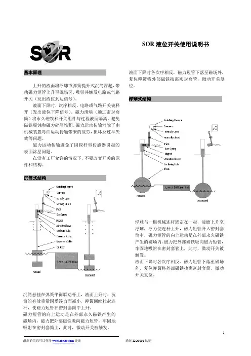
sor液位开关中文说明书基本原理上升的液面将浮球或弹簧提升式沉筒浮起,带动磁力短管上升至磁场区,吸引并触发电路或气路开关(发出液位到达信号)。
液面下降时,次序相反,电路或气路开关被释开(发出液位下降信号)。
磁力滑块(通过密封套筒)将永久磁铁和开关组件与过程液面隔离,避免磁铁腐蚀和磁力碎屑堆积。
磁力运动传输消除了由机械装置弯曲运动传输带来的疲劳,损坏及过早失效等问题。
磁力运动传输避免了因探杆型传感器引起的表面涂层问题。
在没有工厂允许的情况下,不要改变开关的原件和结构。
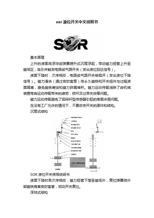
沉筒式结构SOR液位开关使用说明书液面下降时各次序相反,磁力短管下落至磁场外,复位弹簧将外部磁铁拽离密封套管,微动开关复位。
浮球式结构浮球与一根机械连杆固定在一起,液面上升至浮球,浮力使连杆上升,磁力短管升入密封套筒中,磁力短管的向上运动是在外部永久磁铁产生的磁场内。
磁力把外部磁铁吸向磁力短管,牢固地吸附在密封套管上,此时,微动开关被触发。
液面下降时各次序相反。
磁力短管下落至磁场外,复位弹簧将外部磁铁拽离密封套筒,微动开关复位。
沉筒悬挂在弹簧平衡联动杆上,液面上升时,沉筒的有效重量因受浮力而减小,弹簧回缩拉起连杆,使磁力短管在密封套筒中上升。
磁力短管的向上运动是在外部永久磁铁产生的磁场内,磁力把外部磁铁吸向磁力短管,牢固地吸附在密封套筒上,此时,微动开关被触发。
引压口联接外浮筒接管应当平直且不受干扰,控制头与外浮筒垂直中心线在3℃内。
注意:顶装式控制头与容器法兰或短管安装成与容器的垂直或水平中心线不超过3℃。
(即:外浮筒式与顶装式均应垂直安装)接管长度应控制在最小,以使开关整体更稳定。
如有需要,应采用接管悬挂或支承装置。
控制机构在液体中动作,接管中很可能堆积沉淀物,应采用“T”形或“+”形管接头,允许定期清洗接管。
排污阀及吹扫阀可用于清洁外浮筒和接管。
正常运行中,所有接管上阀门应完全打开,因为限流可能导致误动作。
警告:介质温度超过232℃时,不推荐在外浮筒上使用保温材料。
TI00375F/00/EN/13.1371210347Technical InformationLiquipoint T FTW31, FTW32ConductivePoint level switch for multiple point detection in conductiveliquidsApplicationsThe Liquipoint T is used for point level measurement in conductive liquids (from 10 S/cm).Depending on the number of measuring points (up to 5 rods or ropes), measuring tasks such as overfillprotection, dry running protection, two-point control of pumps or multiple point detection can be implemented.Your benefits•Detect up to five point levels with one probe •Two-point control and additional MAX and MIN detection•Option between rod or rope version for optimum adaptation to the application •Flexible instrumentation:–with built-in electronic insert, either transistor (PNP) or relay output–for connection to a separate transmitter power supply unit •No adjustment required;standard setting for the most common conductive liquids•No moving parts in the tank:–long service life–reliable operation with no wear or blockages •WHG approval•Easy adaptation to different conductivitiesLiquipoint T FTW31, FTW322Endress+HauserTable of contentsFunction and system design. . . . . . . . . . . . . . . . . . . . .3Measuring principle . . . . . . . . . . . . . . . . . . . . . . . . . . . . . . . . . . . 3Measuring system . . . . . . . . . . . . . . . . . . . . . . . . . . . . . . . . . . . . . 3Input . . . . . . . . . . . . . . . . . . . . . . . . . . . . . . . . . . . . . .5Measured variable . . . . . . . . . . . . . . . . . . . . . . . . . . . . . . . . . . . . 5Measuring range (application) . . . . . . . . . . . . . . . . . . . . . . . . . . . . 5Input signal . . . . . . . . . . . . . . . . . . . . . . . . . . . . . . . . . . . . . . . . . 5Output. . . . . . . . . . . . . . . . . . . . . . . . . . . . . . . . . . . . .5Electronic insert FEW52 (DC-PNP) . . . . . . . . . . . . . . . . . . . . . . . 5Electronic insert FEW54 (relay) . . . . . . . . . . . . . . . . . . . . . . . . . . 6Electronic insert FEW58 (NAMUR) . . . . . . . . . . . . . . . . . . . . . . . 8Cable monitoring . . . . . . . . . . . . . . . . . . . . . . . . . . . . . . . . . . . . . 8Power supply. . . . . . . . . . . . . . . . . . . . . . . . . . . . . . . .9Compact instrument version with FEW52 . . . . . . . . . . . . . . . . . . 9Compact instrument version with FEW54 . . . . . . . . . . . . . . . . . 10Compact instrument version with FEW58 . . . . . . . . . . . . . . . . . 11Separate instrumentation for probes with two rods or ropes with cable monitoring . . . . . . . . . . . . . . . . . . . . . . . . . . . . . . . . . . . . . . . . . 11Separate instrumentation for probes with three rods or ropes with cable monitoring . . . . . . . . . . . . . . . . . . . . . . . . . . . . . . . . . . . . 12Separate instrumentation for probes with five rods or ropes with cable monitoring . . . . . . . . . . . . . . . . . . . . . . . . . . . . . . . . . . . . . . . . . 12Cable entry . . . . . . . . . . . . . . . . . . . . . . . . . . . . . . . . . . . . . . . . 13Cable specifications . . . . . . . . . . . . . . . . . . . . . . . . . . . . . . . . . . 13Performance characteristics. . . . . . . . . . . . . . . . . . . .13Reference operating conditions . . . . . . . . . . . . . . . . . . . . . . . . . . 13Measuring error . . . . . . . . . . . . . . . . . . . . . . . . . . . . . . . . . . . . . 13Non-repeatability . . . . . . . . . . . . . . . . . . . . . . . . . . . . . . . . . . . . 13Hysteresis . . . . . . . . . . . . . . . . . . . . . . . . . . . . . . . . . . . . . . . . . . 13Switch-on delay . . . . . . . . . . . . . . . . . . . . . . . . . . . . . . . . . . . . 13Influence of ambient temperature . . . . . . . . . . . . . . . . . . . . . . . . 13Installation. . . . . . . . . . . . . . . . . . . . . . . . . . . . . . . . .13Mounting location . . . . . . . . . . . . . . . . . . . . . . . . . . . . . . . . . . . 13Orientation of probes . . . . . . . . . . . . . . . . . . . . . . . . . . . . . . . . . 14Example applications . . . . . . . . . . . . . . . . . . . . . . . . . . . . . . . . . 14Environment . . . . . . . . . . . . . . . . . . . . . . . . . . . . . . .15Ambient temperature range . . . . . . . . . . . . . . . . . . . . . . . . . . . . 15Storage temperature . . . . . . . . . . . . . . . . . . . . . . . . . . . . . . . . . . 15Climate class . . . . . . . . . . . . . . . . . . . . . . . . . . . . . . . . . . . . . . . 15Degree of protection . . . . . . . . . . . . . . . . . . . . . . . . . . . . . . . . . . 15Shock resistance . . . . . . . . . . . . . . . . . . . . . . . . . . . . . . . . . . . . . 15Vibration resistance (at min. rod length) . . . . . . . . . . . . . . . . . . . 15Electromagnetic compatibility . . . . . . . . . . . . . . . . . . . . . . . . . . . 15Process . . . . . . . . . . . . . . . . . . . . . . . . . . . . . . . . . . .15Conductivity . . . . . . . . . . . . . . . . . . . . . . . . . . . . . . . . . . . . . . . 15Limiting medium pressure range . . . . . . . . . . . . . . . . . . . . . . . . 15Environment . . . . . . . . . . . . . . . . . . . . . . . . . . . . . . . . . . . . . . . 16Mechanical construction . . . . . . . . . . . . . . . . . . . . . .16Weights . . . . . . . . . . . . . . . . . . . . . . . . . . . . . . . . . . . . . . . . . . . 17Material . . . . . . . . . . . . . . . . . . . . . . . . . . . . . . . . . . . . . . . . . . . 17Fitted electrodes . . . . . . . . . . . . . . . . . . . . . . . . . . . . . . . . . . . . 17Human interface . . . . . . . . . . . . . . . . . . . . . . . . . . . .18Operating elements . . . . . . . . . . . . . . . . . . . . . . . . . . . . . . . . . . 18Display elements . . . . . . . . . . . . . . . . . . . . . . . . . . . . . . . . . . . . 18Certificates and approvals . . . . . . . . . . . . . . . . . . . . .19CE mark . . . . . . . . . . . . . . . . . . . . . . . . . . . . . . . . . . . . . . . . . . 19Overfill protection . . . . . . . . . . . . . . . . . . . . . . . . . . . . . . . . . . . 19Other standards and guidelines . . . . . . . . . . . . . . . . . . . . . . . . . . 19Ex-approvals . . . . . . . . . . . . . . . . . . . . . . . . . . . . . . . . . . . . . . . 19Type of protection . . . . . . . . . . . . . . . . . . . . . . . . . . . . . . . . . . . 19Ordering information. . . . . . . . . . . . . . . . . . . . . . . . .19Accessories . . . . . . . . . . . . . . . . . . . . . . . . . . . . . . . .19Liquipoint T . . . . . . . . . . . . . . . . . . . . . . . . . . . . . . . . . . . . . . . 19Documentation . . . . . . . . . . . . . . . . . . . . . . . . . . . . .20Operating Instructions. . . . . . . . . . . . . . . . . . . . . . . . . . . . . . . . 20Certificates . . . . . . . . . . . . . . . . . . . . . . . . . . . . . . . . . . . . . . . . 20Liquipoint T FTW31, FTW32Function and system designMeasuring principle An alternating voltage exists between the probe rods. As soon as a conductive liquid creates a connectionbetween the ground probe rod and, for example, the MAX probe rod, a measurable current flows and theLiquipoint T switches.With point level detection, the device switches back as soon as the liquid clears the MIN probe.With two-point control, the device does not switch back until the MAX and MIN probe is cleared.Using alternating voltage prevents corrosion of the probe rods and electrolytic destruction of the product.The material used for the tank walls is not relevant for measurement because the system is designed as a closed,potential-free circuit between the probe rods and the electronics.There is absolutely no danger if the probe rods are touched during operation.Measuring system Probes without an integrated electronic insert (separate instrument version) forone- or two-point detectionThe measuring system consists of:• FTW31, FTW32 with two/three rods or ropes• One or two Nivotester FTW325• Control units, switches or signal transmitters, e.g. process control systems PLC, relays, etc.Switch points, depending on the tank materialEndress+Hauser3Liquipoint T FTW31, FTW324Endress+HauserProbes without integrated electronic insert for multiple point detection The measuring system consists of:• FTW31, FTW32 with five rods or ropes • Two or three Nivotester FTW325• Control units, switches or signal transmitters, e.g. process control systems PLC, relays, etc.Switch points, depending on the tank materialProbes with integrated electronic insert (compact instrument version)The measuring system consists of:• FTW31 with rods or FTW32 with ropes and an electronic insert• Control units, switches or signal transmitters, e.g. process control systems PLC, relays, etc.Independent of the tank material!Note!The compact instrument version with three rods or ropes is always operated in s mode.Liquipoint T FTW31, FTW32Endress+Hauser 5InputMeasured variableResistance change between two conductors caused by the presence or absence of a conductive liquid.Measuring range (application)The measuring range is dependent on the mounting location of the probes.Rod probes can have a max. length of 4 m (13 ft), and rope probes can have a max. length of 15 m (49 ft). Input signalProbes covered => a measurable current is flowing between the probes.Probes uncovered => there is no measurable current flowing between the probes.OutputElectronic insert FEW52 (DC-PNP)Output signalThree-wire direct current versionPreferred in conjunction with programmable logic controllers (PLC). Positive signal at the switch output of the electronics (PNP).The output is blocked after the point level is reached.*1 = Load current (connected); *2 Residual current (disconnected); *3 LED not lit; *4 LED lit See also "Output signal" ä5.If the probe is covered and the red LED flashes continuously, the sensitivity setting is too high. To ensure a safe switch status even if the conductivity of the medium varies slightly, reduce the sensitivity setting. Fail-safe modeSelecting the correct fail-safe mode ensures that the output always runs in quiescent current fail-safe.•MAX fail-safe mode (MAX): The output voltage is 0 V if the switch point is exceeded (probe covered), a fault occurs or the power supply fails.•MIN fail-safe mode (MIN): The output voltage is 0 V if the switch point is undershot (probe uncovered), a fault occurs or the power supply fails.Switching delayA switching delay of 2.0 s can be activated or deactivated via a DIL switch.If the switching delay is set to 0 s, the device switches after approx. 0.3 s.Liquipoint T FTW31, FTW326Endress+HauserSensitivityThe device operates in one of four sensitivity levels (100 Ω, 1 k Ω, 10 k Ω or 100 k Ω). The sensitivity level is set using two DIL switches (SENS). Setting on delivery: 100 k Ω (maximum sensitivity).Signal on alarmIn the event of a power failure or a damaged probe: < 100 μA Load•Load is switched via a transistor (PNP).•Cycled overload and short-circuit protection, continuous ≤200 mA (short-circuit proof) •Residual voltage at transistor at I max : <2.9 VElectronic insert FEW54 (relay)Output signalAC/DC connection with relay output Both relay contacts switch simultaneously.*1 = Relay energized; *2 Relay de-energized; *3 LED not lit; *4 LED lit See also "Power supply" →ä9.If the probe is covered and the red LED flashes continuously, the sensitivity setting is too high. To ensure a safe switch status even if the conductivity of the medium varies slightly, reduce the sensitivity level.Liquipoint T FTW31, FTW32Fail-safe modeSelecting the correct fail-safe mode ensures that the relay always runs in quiescent current fail-safe.•MAX safety (MAX): The relay de-energizes when the switch point is exceeded.(probe covered), a fault occurs or the power supply fails.•MIN safety (MIN): The relay de-energizes when the switch point is undershot.(probe uncovered), a fault occurs or the power supply fails.SensitivityThe device operates in one of four sensitivity levels (100 Ω, 1 kΩ, 10 kΩ or 100 kΩ).The sensitivity level is set using 2 DIL switches (SENS).Setting on delivery: 100 kΩ (maximum sensitivity)Switching delayA switching delay of 2.0 s can be activated or deactivated via a DIL switch.If the switching delay is set to 0 s, the device switches after approx. 0.3 s.Signal on alarmOutput signal in the event of a power failure or a damaged probe: relay de-energized.LoadLoads are switched via 2 potential-free change-over contacts.I~ max. 4 A, U~ max. 253 V;P~ max. 1000 VA, cos ϕ = 1, P~ max. 700 VA, cos ϕ > 0.7;I– max. 4 A to 30 V, I– max. 0.2 A to 150 V.When connecting a functional extra-low voltage circuit with double insulation in accordance withIEC 1010: the sum of the relay output and power supply voltages is max. 300 V.Galvanic isolationAll input channels, output channels and relay contacts are galvanically isolated from each other.Endress+Hauser7Liquipoint T FTW31, FTW328Endress+HauserElectronic insert FEW58 (NAMUR)Output signalFor connecting to isolating amplifiers acc. to NAMUR (IEC 60947-5-6) e.g. Nivotester FTL325N from Endress+Hauser.Output signal jump from high to low current on point level (H-L edge).Fail-safe modeSelecting the correct fail-safe mode ensures that the relay always runs in quiescent current fail-safe.•MAX safety (MAX): The output signal is <1.0 mA when the switch point is exceeded (probe covered), a fault occurs or the power supply fails.•MIN safety (MIN): The output signal is <1.0 mA when the switch point is undershot (probe uncovered), a fault occurs or the power supply fails.SensitivityThe device operates in one of four sensitivity levels (100 Ω, 1 k Ω, 10 k Ω or 100 k Ω).The sensitivity level is set using two DIL switches (SENS). Setting on delivery: 100 k Ω (maximum sensitivity)Switching delayA switching delay of 2.0 s can be activated or deactivated via a DIL switch.If the switching delay is set to 0 s, the device switches after approx. 0.3 s.LoadRefer to the "Technical Data" of the connected isolating amplifier acc. to NAMUR (IEC 60947-5-6)Cable monitoringFor probes without an electronic insert, an additional printed circuit board is installed in the housing to enable cable monitoring. It is always switched or connected between rod/rope 1 and 2.!Note!When using switching units (transmitters) that do not support cable monitoring, these must be removed.L00-FTL5xxxx-07-05-xx-xx-002= lit = flashes = unlitLiquipoint T FTW31, FTW32Endress+Hauser 9Power supplyCompact instrument version with FEW52Transistor circuit for loadThe load connected to terminal 3 is switched by a transistor, contactless and therefore without bouncing. In normal switch status, terminal 3 has a positive signal.The transistor is blocked in the event of a level alarm or a power failure.Protection against voltage peaksWhen connecting a device with high inductance, always connect a voltage limiter.Connecting the FEW52 electronic insert F: Fine-wire fuse 500 mA, semi-time lag M: Ground connection to protective earthSupply voltage (FEW52)•Supply voltage: U= 10.8 V to 45 V •Load connection: open collector; PNP •Switching voltage: max. 45 V•Connected load, continuous: max. 200 mA •Protected against reverse polarityPower consumption P < 1.1 WCurrent consumption I < 25 mA (without load)Liquipoint T FTW31, FTW3210Endress+HauserCompact instrument version with FEW54Relay contact circuit for loadThe connected load is switched via potential-free relay contacts (change-over contact).In the event of a level alarm or a power failure, the relay contacts break the connections between terminals 3 and 4 and terminals 6 and 7. The relays always switch simultaneously.Protection against voltage peaks and short-circuitsWhen connecting a device with high inductance, fit a spark barrier to protect the relay contact. A fine-wire fuse (load-dependent) can protect the relay contact in the event of a short-circuit.L00-FTW3xxxx-04-05-xx-en-002Connecting the FEW54 electronic insert F1: Fine-wire fuse 500 mA, semi-time lagF2: Fine-wire fuse to protect the relay contact, load-dependent M: Ground connection to protective earth (PE)Supply voltage (FEW54)•Supply voltage: U % 20 V to 55 V DC or U & 20 V to 253 V AC, 50/60 Hz •Peak inrush current: max. 2 A, max. 400 μs •Output: two potential-free change-over contacts•Contact load capacity: U~ max. 253 V, I~ max. 4 A, U % 30 V/4 A; 150 V/ 0.2 APower consumption P < 2.0 WCurrent consumption I <60 mALiquipoint T FTW31, FTW32Endress+Hauser 11Compact instrument version with FEW58To be used with a separate switching unit acc. to IEC 60947-5-6 (NAMUR) e.g. Nivotester FTL325N from Endress+Hauser; Output signal jump from high to low current on point level (H-L edge). Signal transmission on a two-wire line:H-L-edge 2.2 to 6.5 mA / 0.4 to 1.0 mAWhen using a multiplex the cycle time must be set to a minimum of 2 s.Connecting the FEW58 electronic insertSupply voltage (FEW58)Refer to the "Technical Data" of the connected isolating amplifier acc. to IEC 60947-5-6 (NAMUR) e.g. Nivotester FTL325N from Endress+Hauser.Signal on alarmOutput signal with damaged sensor: < 1.0 mASeparate instrumentation for probes with two rods or ropes with cable monitoring*1Printed circuit board for cable monitoring (only required for probes with WHG certification.)The power supply and evaluation are provided by switching units, e.g. Nivotester FTW325Liquipoint T FTW31, FTW3212Endress+HauserSeparate instrumentation for probes with three rods or ropes with cable monitoring*1Printed circuit board for cable monitoring (only required for probes with WHG certification.)The power supply and evaluation are provided by a switching unit, e.g. Nivotester FTW325Separate instrumentation for probes with five rods or ropes with cable monitoring*1Printed circuit board for cable monitoring (only required for probes with WHG certification.)The power supply and evaluation are provided by a switching unit, e.g. Nivotester FTW325Liquipoint T FTW31, FTW32Endress+Hauser 13Cable entry M 20x1.5 and NPT 1/2 "•Quantity in F24 housing: 1 (separate instrument version)•Quantity in F16 housing: 2 (compact instrument version)•Conductor cross-section (including wire end sleeve): 2.5 mm² (14 AWG)Cable specifications Use a commercially available cable (25 Ω per wire).Performance characteristics!Note!When electronic insert is installed!Reference operating condi-tions•Ambient temperature: 23 °C (73 °F)•Medium temperature: 23 °C (73 °F)•Medium viscosity: medium must release the probe again (drain off). •Medium pressure p e : 0 bar (0 psi)•Probe installation: vertically from aboveMeasuring error±10 % at 100 Ω - 100 k Ω±5 % at 1 k Ω - 10 k ΩNon-repeatability±5 % at 100 Ω - 100 k Ω±1 % at 1 k Ω - 10 k ΩHysteresis – 10% for the MAX probe, in reference to the switch point. ∆s function disabled.Switch-on delay< 3 s Influence of ambient tempera-ture< 0.05 %/KInstallationMounting locationTanksThe rod and rope probes are mounted predominantly in tanks. Piping (partially filled)Two-rod probes can be used in piping as, for example, dry running protection for pumps.Liquipoint T FTW31, FTW32 Orientation of probes Point level detectionExample applications Point level detection: Two-point control (∆s)Two-point control (∆s) e.g. pump control14Endress+HauserLiquipoint T FTW31, FTW32Endress+Hauser 15Point level detection: MAX and MIN detectionPoint level detection (MAX),MAX and MIN detection for compact instrument version only possible with ∆s.EnvironmentAmbient temperature rangeNon-hazardous area•–40 to 70 °C (–40 to 158 °F)•–40 to 60 °C (–40 to 140 °F) for FEW58 NAMURStorage temperature –40 to 80 °C (–40 to 176 °F)Climate class Tropicalized as per DIN EEC 68, part 2-38Degree of protection IP66Shock resistance Practical testVibration resistance (at min. rod length)DIN 60068-2-64 / IEC 68-2-64: 20 to 2000 Hz, 1 (m/s 2)2/HzElectromagnetic compatibility•Interference Emission to EN 61326, Electrical Equipment Class B Interference Immunity to EN 61326, Annex A (Industrial)•Use for separate-instrumented probes a screened cable between the probe and the switching unit.For installation instructions for screened cables and general instructions for EMC inspection conditions for E+H devices, see also TI00241F.ProcessConductivity≥10 μSLimiting medium pressure range–1 to 10 bar (–1 psi)Liquipoint T FTW31, FTW3216Endress+HauserEnvironmentPermissible ambient temperature T 1 at the housing as a function of the measuring material temperature T 2 in the vessel:!Note!For separately instrumented devices (without FEW5x) there are no restrictions in the indicated temperature range.Mechanical construction!Note!All dimensions in mm (in)!Liquipoint T FTW31, FTW32Endress+Hauser 17WeightsMaterial Wetted •Seal between probe rod/probe rope and process connection: EPDM •Spacer: PP•Flat seal for process connection: elastomer fiber, (asbestos-free)•Process connections: –G 1 ½: PPS –NPT 1 ½: PPSProbe rods•Rod: 316L (1.4404) or carbon fiber •Insulation: PP Probe ropes•Rope: 316Ti (1.4571)•Insulation: FEP•Weight: 316L (1.4435)Not wetted•Plastic housing F24 (separate instrument version)–Housing: PPS –Cover: PBT•Polyester housing F16: PBT-FR with PBT-FR cover or with PA12 transparent cover,–Cover seal: EPDM –Adapter: PBT-FR–Nameplate, glued: polyester foil (PET)–Pressure compensation filter: PBT-GF20•Ground terminal on housing (outside): 304 (1.4301)•Cable gland: polyamide (PA)Fitted electrodesRod probesCompact instrument version: 2 or 3 rods; Separate instrument version: 2, 3 or 5 rods •Diameter without insulation: 4 mm (0.16 in)•Maximum rod length: 4000 mm (157 in)•Minimum rod length: 100 mm (3.94 in)•Thickness of insulation: 0.5 mm (0.02 in)•Length of non-insulated area (tip of rod): 20 mm (0.79 in)•Extraction forces (parallel probe rod): 1000 N (224.8 lbf)Rope probesCompact instrument version: 2 or 3 rods; Separate instrument version: 2, 3 or 5 rods •Diameter without insulation: 1 mm (0.04 in)•Maximum rope length: 15000 mm (591 in)•Minimum rope length: 250 mm (9.84 in)•Thickness of insulation: 0.75 mm (0.03 in)•Weight length: 100 mm ( 3.94 in) not insulated •Weight diameter: 10 mm (0.39 in)•Extraction forces (parallel probe rod): 500 N (112.4 lbf)Separate instrument version2, 3 or 5 probesRod 1 m (3.3 ft) length 415 g, 530 g, 760 g (14.64 oz, 18.69 oz, 26.81 oz)Rope 1 m (3.3 ft) length 390 g, 470 g, 640 g (13.76 oz, 16.58 oz, 22.57 oz)Compact instrument version2 or3 probesRod 1 m (3.3 ft) length 600 g, 720 g (21.16 oz, 25.40 oz)Rope 1 m (3.3 ft) length710 g, 800 g (25.04 oz, 28.22 oz)Liquipoint T FTW31, FTW32Human interfaceOperating elements FEW52, FEW54, FEW58One DIL switch for MIN or MAX safetyOne DIL switch for 0 s or 2 s switching delayTwo DIL switches for setting the sensitivity level 100 Ω, 1 kΩ, 10 kΩ or 100 kΩDisplay elements Separate instrument versionThe display elements are dependent on the connected switching unit.Compact instrument versionFEW52One red light emitting diode: fault message, switch statusOne green light emitting diode: operationL00-FTW3xxxx-07-05-xx-xx-001FEW54One red light emitting diode: fault message, switch statusOne green light emitting diode: operationL00-FTW3xxxx-07-05-xx-xx-002FEW58One yellow light emitting diode: fault message, switch statusOne green light emitting diode: operationL00-FTW3xxxx-07-05-xx-xx-003 18Endress+HauserLiquipoint T FTW31, FTW32Endress+Hauser 19Certificates and approvalsCE markThe Liquipoint T meets the legal requirements of the EC directives. Endress+Hauser confirms that the device has been successfully tested by applying the CE mark.Overfill protection •WHG, leak test (leakage)Other standards and guide-lines•Low voltage equipment directive (73/ 23/ EEC) •DIN EN 61010 part 1, 2001Safety regulations for electrical equipment for measurement, control and laboratory use Part 1: General requirements •EN 61326Electrical equipment for measurement, control and laboratory use EMC requirementsEx-approvalsFor further information, please contact your local Endress+Hauser Sales Center. All data relevant to explosion protection can be found in separate Ex documentation (see: Documentation ä20) . Type of protection•[EEx ia] IIC (FEW58)•[EEx na/C(L)] IIC (FEW52, FEW54)Ordering information!Note!Further details on product configuration and product features can be found in the Online Configurator on the product pages. See: .AccessoriesLiquipoint TLock nut G 1 1/2"•Hexagon: AF 60•Material: PC-FR•Part number: 52014146 Electronic insert FEW52•Output PNP 10.8 to 45 V DC •Part number: 52017271 Electronic insert FEW54•Output relay 20 to 253 V AC, 20 to 55 V DC •Part number: 52017272 Electronic insert FEW58•Output NAMUR (IEC 60947-5-6)•Part number: 52017273Documentation!Note!This documentation can be found on the product pages at "".Operating Instructions Liquipoint T FTW31, FTW32KA204F/00Certificates WHG•Liquipoint T FTW31, FTW32ZE043F/00ATEX II 3G EEx nA/C(L) IIC T6•Liquipoint T FTW31, FTW32XA226F/00ATEX II 2G EEx ia IIC T6•Liquipoint T FTW31, FTW32XA230F/00Instruments InternationalE ndress+HauserInstruments International A GKaegenstrasse 24153 ReinachSwitzerlandTel.+41 61 7158100F ax+41 61 7152500***************.comTI00375F/00/EN/13.1371210347FM 9.071210347。
外贴式液位开关隔爆型安装使用说明书(201405A)陕西声科电子中国西安高新技术产业开发区©本说明书的版权和最终解释权归声科电子有限公司所用。
目录1.使用说明 (1)2.仪表保修及服务范围 (1)3.仪表技术性能 (2)4.开箱检验及注意事项 (2)4.1 开箱检验 (2)4.2 注意事项 (3)5.仪表各部件 (3)6.仪表安装 (4)6.1 超声波探头的安装 (4)6.2 仪表主机安装 (8)6.3仪表的安装方式 (11)7.仪表电气连接 (12)7.1 仪表电气连接图 (12)7.2 仪表供电 (12)8. 仪表设置及使用 (13)8.1 仪表参数设置人机接口说明 (13)8.2 仪表操作目录树 (14)8.3 仪表运行界面示意 (15)8.4 仪表校准操作 (16)8.5仪表校准操作图示 (16)9.外贴式液位开关选型表 (19)10.仪表适用范围 (20)11.性能指标 (20)12.仪表故障处理 (21)1、使用说明本说明书全面阐述了外贴式液位开关的安装、操作及使用方法。
通过本说明书,用户可以顺利的完成对外贴式液位开关的安装、使用及维护工作。
本说明书的编制是以外贴式液位开关的安装、操作步骤为顺序,详细介绍了您在安装、使用仪表的每个环节需要完成的工作及注意事项。
在您安装、使用该仪表之前,请详细阅读本说明书。
2、仪表保修及服务范围自发货之日算起,仪表主机保修期为一年,仪表修理及维护的保修期为半年,此保修仅限于原始购买者及或声科电子指定经销商的仪表使用用户,而不适用于任何声科电子认为因错误使用,改造、疏忽或因事故及非正常情况下使用而导致损坏的仪表。
对于在保修范围内的送回声科电子的有故障的仪表,声科电子提供免费维修。
要获得保修服务,请联系声科售后服务部并附上故障说明,经本公司许可后,将仪表寄往声科售后服务部。
如果仪表已过质保期或声科电子确认仪表故障是由于错误使用、改造、疏忽、事故及非正常条件下使用导致的,声科电子将依据外贴式液位开关维修收费标准提供维修费用预算,并在得到认可后进行维修。

UK系列液位开关安装使用说明书开封仪表厂液位仪表分厂UK一102球形液位开关使 用 说 明 书l、用途和使用范围UK一1 0 2球形液位开关(以下简称开关)主要是对液位定点发讯,实现生产过程中的报警,控制,调节等作用,在酸、碱溶液或供水、排水、化工污水处理等生产过程中,是不可缺少的工具,开关的主要零件均采用1Cr18Ni9Ti不锈钢制造,具有较好的耐腐蚀性能。
其特点是:经济实用、工作可靠、用途广泛。
2、规格及技术参数2.1 关电缆长度: 4、 5、 6m(或由用户提出一个长度)2.2 介质密度:2.3 介质温度: ≤100℃2.4 工作压力: 0.2MPa一个常开2.5 接点容量: 220V AC 5A2.6 发二个讯号 (一个常开,一个常闭)3、结构原理及安装使用3.1 开关结构简单、结构如图(一)开关外壳为不锈钢球体,表面光滑,不易附着污物,可在混有杂物污水、泥浆、酸、碱溶液中使用,球体内装有大容量的水银开关,水银开关接于软质电缆上,加长或缩短电缆长度,可得到希望水位。
3.2 开关悬空吊在固定杆上,如图(二)a所示,当液位上升液面接触到开关时,开关球体在浮力的作用下发生倾斜,如图(二)b所示,由此使开关球体内水银开关断开或闭合,从而发出信号。
4、订货须知订货时请注明4.1 开关型号及名称4.2 被测介质名称、介质密度、温度、工作压力腐蚀性等。
UK一201球形液位开关使 用 说 明 书UK一201型圆柱形液位开关(以下简称液位开关),主要是对液位定点发讯,实现生产过程中的报警、控制、调节等作用,在供水、排水、化工污水处理等过程中,是不可缺少的工具。
1、主要规格和技术参数1.1 电源:电压220V/50Hz 允许电流5A1.2 环境温度:60℃以下1.3 介质比重: 0.75以上1.4 规格(电缆长度L:)3M、5M、6M或其它任一长度。
1.5 种类:UK一201K 悬吊状态时触点断开浮起状态时触点闭合常开型UK一201B 悬吊状态时触点闭合浮起状态时触点断开常闭型2、结构及工作原理液位开关是浮动开关,它是把特殊构造的水银开关与通用橡套软电缆连在—一起,用环氧树脂(加有填料)浇铸成芯子、安装(插装)在硬质发泡塑料浮上。
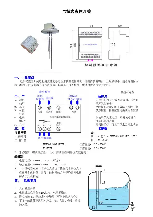
电极式液位开关一、工作原理电极式液位开关是利用液体之导电性来侦测液位高低。
桶槽内装的物质一旦触及极棒,便会导电因而检出信号。
经控制器的信号放大后,再输出一接点信号,供使用者做液位的控制。
接线示意图二、产品特点1、适用于控制任何导电液体之液面。
(禁止使用于挥发性液体)2、具有突波保护功能,可有效防止突波干扰3、可做多点控制,控制位置可由使用者需要订制4、电极头使用低交流电压,可避免电解作用,并可延长使用寿命5、具有两只指示灯,可显示供水及排水状态三、技术参数电极棒部分:1、接液材质(可选):SUS304/316L+PP(PE)工作温度:-20~80℃SUS304/316L+PTFE 工作温度:-20~200℃TI+PTFE 工作温度:-20~200℃2、过程连接:螺纹或法兰,(大小跟所需控制液位点数有关)控制器:1、电源电压:220VAC、24VAC(可选)2、触点容量:240VAC/24VDC 5A, SPDT3、一个控制器对应一个液位点输出(检测几个液位点对应配几个控制器,且每个控制器的公共极均需同电极棒的公共极相连)。
四、注意事项1、只供垂直安装2、电压波动范围在±15%以内,电压要稳定3、避免安装在大震动或冲击场所(可能导致误动作)4、不导电的液体不适用本产品,如:汽油、柴油、重油、纯水等。
5、所有的极棒需与最长的极棒相差至少50mm以上(如图)6、当液体接触到电极时,其动作的作罢会因液体种类不同及电源电压变化而会有变动。
7、为了使电极棒在水中确保不会相互接触,可以在极棒上缠上胶带,但必须缠在极棒前端100mm以后的部分。
基本原理上升的液面将浮球或弹簧提升式沉筒浮起,带动磁力短管上升至磁场区,吸引并触发电路或气路开关(发出液位到达信号)。
液面下降时,次序相反,电路或气路开关被释开(发出液位下降信号)。
磁力滑块(通过密封套筒)将永久磁铁和开关组件与过程液面隔离,避免磁铁腐蚀和磁力碎屑堆积。
磁力运动传输消除了由机械装置弯曲运动传输带来的疲劳,损坏及过早失效等问题。
磁力运动传输避免了因探杆型传感器引起的表面涂层问题。
在没有工厂允许的情况下,不要改变开关的原件和结构。
沉筒式结构液面下降时各次序相反,磁力短管下落至磁场外,复位弹簧将外部磁铁拽离密封套管,微动开关复位。
浮球式结构SOR液位开关使用说明书浮球与一根机械连杆固定在一起,液面上升至浮球,浮力使连杆上升,磁力短管升入密封套筒中,磁力短管的向上运动是在外部永久磁铁产生的磁场内。
磁力把外部磁铁吸向磁力短管,牢固地吸附在密封套管上,此时,微动开关被触发。
液面下降时各次序相反。
磁力短管下落至磁场外,复位弹簧将外部磁铁拽离密封套筒,微动开关复位。
沉筒悬挂在弹簧平衡联动杆上,液面上升时,沉筒的有效重量因受浮力而减小,弹簧回缩拉起连杆,使磁力短管在密封套筒中上升。
磁力短管的向上运动是在外部永久磁铁产生的磁场内,磁力把外部磁铁吸向磁力短管,牢固地吸附在密封套筒上,此时,微动开关被触发。
引压口联接外浮筒接管应当平直且不受干扰,控制头与外浮筒垂直中心线在3℃内。
注意:顶装式控制头与容器法兰或短管安装成与容器的垂直或水平中心线不超过3℃。
(即:外浮筒式与顶装式均应垂直安装)接管长度应控制在最小,以使开关整体更稳定。
如有需要,应采用接管悬挂或支承装置。
控制机构在液体中动作,接管中很可能堆积沉淀物,应采用“T”形或“+”形管接头,允许定期清洗接管。
排污阀及吹扫阀可用于清洁外浮筒和接管。
正常运行中,所有接管上阀门应完全打开,因为限流可能导致误动作。
警告:介质温度超过232℃时,不推荐在外浮筒上使用保温材料。
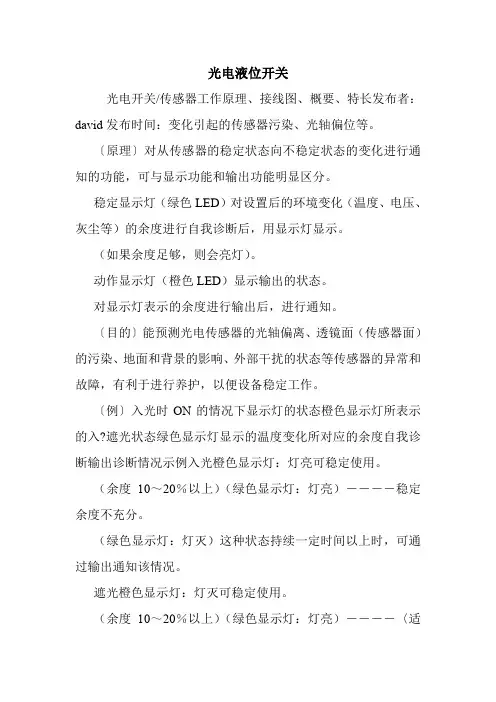
光电液位开关光电开关/传感器工作原理、接线图、概要、特长发布者:david发布时间:变化引起的传感器污染、光轴偏位等。
〔原理〕对从传感器的稳定状态向不稳定状态的变化进行通知的功能,可与显示功能和输出功能明显区分。
稳定显示灯(绿色LED)对设置后的环境变化(温度、电压、灰尘等)的余度进行自我诊断后,用显示灯显示。
(如果余度足够,则会亮灯)。
动作显示灯(橙色LED)显示输出的状态。
对显示灯表示的余度进行输出后,进行通知。
〔目的〕能预测光电传感器的光轴偏离、透镜面(传感器面)的污染、地面和背景的影响、外部干扰的状态等传感器的异常和故障,有利于进行养护,以便设备稳定工作。
〔例〕入光时ON的情况下显示灯的状态橙色显示灯所表示的入?遮光状态绿色显示灯显示的温度变化所对应的余度自我诊断输出诊断情况示例入光橙色显示灯:灯亮可稳定使用。
(余度10~20%以上)(绿色显示灯:灯亮)----稳定余度不充分。
(绿色显示灯:灯灭)这种状态持续一定时间以上时,可通过输出通知该情况。
遮光橙色显示灯:灯灭可稳定使用。
(余度10~20%以上)(绿色显示灯:灯亮)----〈适用机型〉按构成分类型号自我诊断功能登载页显示功能输出功能光纤式E3X-DA-S数字显示●68E3X-MDA数字显示-E3X-NA●●86放大器分离型E3C-LDA数字显示●108E3C●●(E3C-JC4P)124E3Z●*140E3T●-190E3S-C●-200E3S-CL●-210E3S-CR62/67●-312E3S-R●-318关于E3Z的自我诊断输出型,请咨询。
⑥外部诊断输入功能(投光停止功能)〔原理〕通过将对射型投光器的导线「粉」「蓝」间短路,可在任意时间使投光停止。
投光器和受光器间没有检测物体时,即使对投光器进行ON/OFF设置,如果受光器侧的输出没有ON/OFF,说明传感器发生异常。
〔目的〕通过该功能,在工作前可进行传感器的动作检查。
共通注意事项★各商品的注意事项,请参见各商品的「请正确使用」。
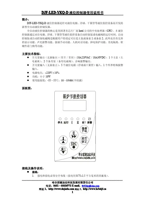
简介:DJF-LED-YKQ-D液位控制器是针对液位电极、浮球、干簧管等液位监控设备而开发的新型全自动液位控制仪器。
全自动液位控制器的核心是美国著名芯片厂商Intel公司的中央处理器(CPU)。
本液位控制器通过水位电极、浮球、干簧管等液位监控设备自动控制泵或电磁阀的运行时间。
自动控制泵或自动控制电磁阀是根据用户的设定可以是主泵或备泵1或备泵2.。
此外还具有完善的显示功能、声光报警功能、强制手动功能、人机对话功能、掉电保护功能、光电隔离、软硬件看门狗等功能。
主要技术指标:�开关量输出(无源输出)(常开/常闭)(10A220V AC/10A30VDC):1个主泵(主电磁阀)、2个备用泵(备用电磁阀)、音响报警输出。
�开关量输入(无源接点):5个液位电极(浮球或干簧管)输入、1个外界特殊报警输入。
�电源电压:~220V±10%�功耗:小于10W�使用温湿度:-55~55℃;35~85%RH(不结露)面板图:接线及操作说明:�接线:1.强电和弱电必须分开布线(弱电用0.75~1.5平方毫米的屏蔽线)。
哈尔滨德加法科技发展有限责任公司电话:0451-55536773E-mail:****************2.公共端:所有的弱电信号的公共端子是通用的,特此说明。
3.液位输入信号接线:公共端接测量筒壳体、按液位的低到高顺序依次接极低液位端子、低液位端子、正常液位端子、高液位端子、极高液位端子。
注:此端子不能带电!4.外界特殊报警输入信号接线:此端子是根据用户的特殊要求可接可不接。
与公共端子一起接外界特殊报警开关的常开触点。
注:此端子不能带电!5.强电输出端子接线:报警输出端子是当控制器发出音响报警时候触点合上。
主泵输出端子是接主泵的控制线圈。
2个备用泵输出端子是接2个备用泵的控制线圈。
电源输入端子是接标准交流220V,N是零线,L是火线。
注:强电端子根据用户的需要可接可不接!�操作符号含义:液位极低报警显示:S-E。
LIQUID LEVEL SWITCHES – Installation, Operation and Compatibility GuideTo ensure the best performance from your equipment it is important that the attached liquid level switch is installed and maintained correctly.This document provides an overview of SST Sensing’s liquid level switches including mounting information, operating principle and fluid compatibility.Contents1 DEFINITIONS ........................................................................................................................... 1-12 TECHNICAL SPECIFICATIONS ................................................................................................... 2-13 INSTALLATION ........................................................................................................................ 3-1 3.1 General Guidelines .......................................................................................................... 3-13.2 Electrical Connections ..................................................................................................... 3-24 OPERATION ............................................................................................................................ 4-1 4.1 Operating Principle Overview .......................................................................................... 4-1 4.2 Fluid Compatibility Guide ................................................................................................ 4-24.3 Test Process .................................................................................................................... 4-45 MAINTENANCE ....................................................................................................................... 5-1 5.1 Cleaning .......................................................................................................................... 5-1 5.2 Disposal .......................................................................................................................... 5-11DEFINITIONSThe following definitions apply to WARNINGS, CAUTIONS and NOTES used throughout this manual.WARNING:The warning symbol is used to indicate instructions that, if they are not followed, can result in minor, serious or even fatal injuries to personnel.CAUTION:The caution symbol is used to indicate instructions that, if they are not followed, can result in damage to the equipment (hardware and/or software), or a system failure occurring.NOTE: Highlights an essential operating procedure, condition or statement.2TECHNICAL SPECIFICATIONSThe following table summarises the key technical specifications. Refer to the appropriate datasheet for more in-depth information (see REFERENCE DOCUMENTS).Switch VoltageRange TemperatureRangeOutputCurrentOutputTypeOutputLogicOptomax Digital 4.5 to 15.4V DC-25 to + 80o Cor-40 to +125o C Up to100mAPush Pull High in AirLow in AirPWMOptomax Industrial 4.5 to 15.4V DCor8 to 30 V DC -25 to + 80o Cor-40 to +125o CUp to1AN-TypeP-TypePush PullHigh in AirLow in AirOptomax Industrial Glass 4.5 to 15.4V DCor8 to 30V DC -40 to +125o C Up to1AN-TypeP-TypePush PullHigh in AirLow in AirLLHP 4.5 to 15.4V DCor10 to 45V DC -25 to + 80o Cor-40 to +125o CUp to800mAN-TypeP-TypePush PullHigh in AirLow in AirPOS 12 to 28V DC-25 to 100o Cor-40 to + 140o C Up to200mAN-TypeP-TypeHigh in AirLow in AirOptomax Basic a 3.3 to 24V DC -25 to + 80o C 4mA Phototransistor outputfor customer tointerface to theirsystemNOTE: If you need a switch other than those listed above, contact SST Sensing; we will be happy to discuss your requirements.a Designed primarily for price sensitive, high volume OEM applications; power supply and microcontroller not supplied with this switch.3INSTALLATIONTo ensure the best performance from your product, it must be installed correctly.3.1General GuidelinesOptical liquid level switches should be mounted from the side or from the bottom for best results.NOTE: Mounting from the top down is not normally advised as false readings can be caused by liquid droplets clinging to the sensing tip. However, if the liquid viscosity is low, then pointing downwards if often fine. Additionally, if the application is a high level alarm and its activation results in the machine shutdown for example, pointing downwards may be acceptable.If you wish to mount in this position, contact SST Sensing to discuss the implications.Avoid mounting positions where ambient light is likely to point directly at the sensing tip, as false readings can occur.Switch performance can be affected by reflective surfaces in front of the sensing tip. ContactSST Sensing if you wish to use a switch within 10mm of a reflective surface (see NOTE).NOTE:If you are installing an LLG switch, avoid reflective surfaces within 50mm of the sensing tip.Figure 3-1 - Example Mounting Positions3.2Electrical ConnectionsCAUTION:•Do NOT immerse the wires in fluid, over time, this will result in irreparable damage to the switch.•Take care when connecting loads. The minimum load impedance should not exceed Vs/max output current. Check the relevant datasheet BEFORE installation.•Shorting the output to Vs or 0V will result in irreparable damage to the switch.•Do NOT install the switch suspended from the cable.•Avoid exerting excessive tensile force on the cable (e.g. tugging).The liquid level switch termination configuration varies depending on the range and selection ordered (refer to the specific datasheet for more detail); in general, connect as follows:Optomax Digital, Industrial and Glass Tip Ranges∙Vs Red∙Output b Green∙0V BlueLLHP Range c∙Vs Red∙Output b Green or white∙0V Blue or blackPOS Range c∙Vs Brown∙Output b Black∙0V BlueOptomax Basic Range∙3-wire versiono LED Anode Redo Output b Greeno0V Blue ∙4-wire versiono LED Anode Redo Output b Greeno0V LED Blueo0V Phototransistor Blackb Refer to the datasheet for output logic details.c Brad Harrison connector available as an alternative to the cable / flying lead options.4OPERATIONOptical liquid level switches do not measure the liquid level, instead they detect the presence or absence of liquid. For an overview of the switches refer to AN-0061, Liquid Level Switches – Selection Guide, more detailed spec information is contained in the switch datasheets; refer to REFERENCE DOCUMENTS for details.4.1Operating Principle OverviewOptical liquid level switches use an infra-red LED and phototransistor accurately positioned at the base of the sensor tip.When the tip is in air, infra-red light reflects internally round the tip to the phototransistor providing strong optical coupling between the two. When the sensor tip is immersed in liquid, the infra-red light escapes from the tip causing a reduction in the amount of light at the phototransistor which makes the output change state.Sensor Tip in Air Sensor Tip Immersed in Liquid4.2Fluid Compatibility GuideThe environment in which the liquid level switch is operating influences the life of the product. To ensure the switch does not fail prematurely, the following material/fluid compatibility should be noted:4.2.1PolysulfoneWhilst the following list may be used as a guide and gives common industrial fluids that are typically acceptable, we recommend that before use you check that the fluid you wish to use this device in is compatible with Polysulfone. Refer to 4.3 Test Process on page 4-4.Acetic acid – GlacialAcetic acid – 10% Ammonia – 88 Ammonium Hydroxide – 10% Ammonium Chloride – 10% Aviation spiritBenzeneBenzoic acidBleachBrineButaneCalcium NitrateCalcium Hypochlorite Carbon Tetrachloride Chromic acidCopper Sulphate CreosoteCyclohexane CyclohexanolDetergent solutionsDiesel fuelDiethylamineDiethyl EtherDioctyl PhthalateEdible fats & oilsEthanol – 50%Ethyl AlcoholEthylene GlycolFerric Chloride FormaldehydeFormic acid GlycerolHeptaneHydrochloric acid – 10% Hydrochloric acid conc. Hydrogen Peroxide IsopropanolIso-OctaneKeroseneLinseed oilMagnesium Sulphate MethanolMotor oilNitric acid 10%Oils - VegetableOxalic acidPetroleum Ether Potassium Hydroxide – 10% Potassium Hydroxide – 50% Silicone fluidsSilver NitrateSoap solutionSodium ChlorideSodium Hydroxide – 10% Sodium Hydroxide – 50% Sulphuric acid – 10% Transformer oil TurpentineVarnishWaterWhite Spirit4.2.2Trogamid®Whilst the following list may be used as a guide and gives common industrial fluids that are typically acceptable, we recommend that before use you check that the fluid you wish to use this device in is compatible with Trogamid® (EU food-contact grade). Refer to 4.3 Test Process on page 4-4.AcetoneBenzeneBreak Free (lubricating oil) Carbon tetrachloride Econa PG32 (Hydraulic fluid) EthanolEthyl acetateEucalyptus oil Formaldehyde solution Glycerine (DAB6)Heating oilIsopropanol MethanolMountain pine oilPetroleum etherPotassium hydroxide (25 w/w-%) Potassium hydroxide (50 w/w-%) Premium gasoline1,2-propane diolRegular gasTest fuel (M15)TolueneXylene4.2.3GlassGlass tipped switches are extremely robust to most chemicals however, chemicals which will attack glass, for example Hydrofluoric acid, are to be avoided. We recommend that before use you check that the fluid you wish to use this device in is compatible with glass. Refer to 4.3 Test Process on page 4-4.4.3Test ProcessThe chemical compatibility lists are not exhaustive and customers often want to use the switches with liquids that have not been approved before. In this case, a compatibility test should be performed using a sensor made with the material (Polysulfone, Trogamid®, glass or stainless steel) you wish to use.The test is simple and is performed as follows:1.Submerge the sensor tip and threads in the liquid of interest. Do NOT submerge the wires.2.Heat the liquid to the maximum expected operating temperature.CAUTION: Assuming it is safe to do so.3.Leave the switch in this liquid at the maximum operating temperature for two weeks.4.Remove the switch and inspect it for signs of:∙Cracking∙Crumbling∙Crazing∙Melting∙Deformation∙SwellingAssuming the switch appears to be unaffected, it should be tested in accordance with its operating procedure to ensure it remains functional.If the switch passes its functional tests, then the liquid can be considered to be compatible with the switch housing material.5MAINTENANCE5.1CleaningIf cleaning of the tip is necessary (i.e., if there is a buildup of algae or other reside), clean the outer surfaces using alcohol based cleaning agents.CAUTION: If your switch is Polysulfone or Trogamid®, do NOT use chlorinated solvents such as tricholoroethane as these are likely to attack the switch material.5.2DisposalLiquid level switches contain electrical components, for this reason they must be disposed of as electrical waste. Please observe your local regulations.Page | 5-1AN-0041 Rev 8 © 2017 SST SENSING LTD.REFERENCE DOCUMENTSRefer also to the following documents for additional information:CAUTIONDo not exceed maximum ratings and ensure sensor(s) are operated in accordance with their requirements.Carefully follow all wiring instructions. Incorrect wiring can cause permanent damage to the device. SST Sensing Ltd recommend using alcohol based cleaning agents. If your switch is Polysulfone or Trogamid®, do NOT use chlorinated solvents such as trichloroethane as these are likely to attack the switch material.Failure to comply with these instructions may result in product damage.INFORMATIONAs customer applications are outside of SST Sensing Ltd.’s control, the information provided is given without legal responsibility. Customers should test under their own conditions to ensure that theequipment is suitable for their intended application. Before use, check that the fluid in which you wish to use these devices is compatible either with Polysulfone, Trogamid®, glass or stainless steel. For technical assistance or advice, please email: ************************SST SENSING LIMITED, 5 HAGMILL CRESCENT, SHAWHEAD INDUSTRIAL ESTATE, COATBRIDGE, UK, ML5 4NS | e: ******************** | t: +44 (0)1236 459 020 | f: +44 (0)1236 459 026。
光电液位开关选型及使用说明 v1.0使用产品前请仔细阅读用户手册前 言尊敬的用户: 您好!衷心感谢您使用本公司产品,为了让您安全、可靠、准确地使用本产品,请您在使用本产品前务必仔细阅读本产品使用手册! 本产品使用手册详细地介绍了该产品的技术参数、用途、仪器组成、使用操作、注意事项等。
使用前务请仔细阅读使用说明书,以及永久的保证该系列仪表的可靠性和稳定性。
您在实际操作仪表的过程中,一定有新的发现和更切实际的使用方法,您对仪表的外形、结构、功能也会有独到的见解,我们期盼您的直言不讳,提出宝贵的意见,我们将把您的意见转化为动力,投入到完善产品、改进服务等具体行动中去。
谢谢合作!F J-GDY-系列光电液位开关原理、特点FJ-GDY-系列光电液位开关是利用光在两种不同介质界面发生折射的原理,由飞卓科技自主研制生产。
工作原理光电液位开关工作原理如上图所示,产品内部包含一个发光器件和一个光敏器件。
发光器件所发出的光被导入传感器顶部的透镜。
当液体浸没光电液位传感器透镜时,则有部分光会折射到液体中,从而使光敏器件接收不到或只能接收到少量光线。
光电液位传感器通过感应这一变化,由光敏器件驱动内部电气开关,从而启动外部报警或控制电路。
如果没有液体,则发光器件发出的光直接从透镜反射回光敏接收器。
F J-GDY-系列光电液位控制器是一种内置式开关电路的低价位结构紧凑的光电液位开关型传感器,该系列产品具有结构简单、体积小、安装方便;没有机械部件、不需调试;重复性好、节能环保等诸多优点,并可制成耐腐、耐温等特种环境用产品。
通常可用于-25℃~65℃环境各类洁净低粘度非腐蚀作用、非结晶、非冰冻的液体液体的关键点、上下限位点或多点液位准确可靠的测量监控、显示报警和定点控制。
F J-GDY-系列光电液位开关适用于几乎任何大小罐体中的高、中、低液位测量。
产品特点∶1 液面检测准确、高重复性、快速响应;2 可制成多点液位传感器;3 高可靠性、长寿命、免维护;4 免调试、免校验,直接安装即可应用;5 适应环境能力强;6 适应特种容器安装。
TI00375F/28/ZH/13.1371248260Analyse技术资料Liquipoint T FTW31, FTW32液体限位开关用于导电性液体的多点检测应用Liquipoint T 用于导电性液体(min. 10 S/cm)的限位检测。
取决于测量点数量(最多5根传感器杆或传感器缆),可以完成例如泵的溢出保护、空转保护、两点控制或多点检测的测量任务。
优势•使用一个传感器即可实现最多五点检测•两点控制,带高限(MAX)和低限(MIN)检测•杆式传感器和缆式传感器可选,优化适应应用要求•仪表使用灵活:–内置电子插件,带晶体管(PNP)或继电器输出–连接独立变送器供电单元•无需调节:标准设置即可用于大多数常见导电性液体测量•安装在罐体中,无可移动部件:–长使用寿命–无磨损或堵塞,操作可靠•WHG 认证•简单适应不同电导率Liquipoint T FTW31, FTW322Endress+Hauser目录功能与系统设计 . . . . . . . . . . . . . . . . . . . . . . . . . . . . .3测量原理 . . . . . . . . . . . . . . . . . . . . . . . . . . . . . . . . . . . . . . . . . . 3测量系统 . . . . . . . . . . . . . . . . . . . . . . . . . . . . . . . . . . . . . . . . . . 3输入 . . . . . . . . . . . . . . . . . . . . . . . . . . . . . . . . . . . . . .5测量变量 . . . . . . . . . . . . . . . . . . . . . . . . . . . . . . . . . . . . . . . . . . 5测量范围(应用) . . . . . . . . . . . . . . . . . . . . . . . . . . . . . . . . . . . . 5输入信号 . . . . . . . . . . . . . . . . . . . . . . . . . . . . . . . . . . . . . . . . . . 5输出 . . . . . . . . . . . . . . . . . . . . . . . . . . . . . . . . . . . . . .5电子插件FEW52 (DC-PNP) . . . . . . . . . . . . . . . . . . . . . . . . . . . . 5电子插件FEW54 (继电器) . . . . . . . . . . . . . . . . . . . . . . . . . . . . 6电子插件FEW58 (NAMUR) . . . . . . . . . . . . . . . . . . . . . . . . . . . . 8电缆监控 . . . . . . . . . . . . . . . . . . . . . . . . . . . . . . . . . . . . . . . . . . 8电源 . . . . . . . . . . . . . . . . . . . . . . . . . . . . . . . . . . . . . .9一体式仪表(带FEW52电子插件) . . . . . . . . . . . . . . . . . . . . . . 9一体式仪表(带FEW54电子插件) . . . . . . . . . . . . . . . . . . . . . 10一体式仪表(带FEW58电子插件) . . . . . . . . . . . . . . . . . . . . . 11分体式仪表(适用于带电缆监控的双杆或双缆传感器) . . . . 11分体式仪表(适用于带电缆监控的三杆或三缆传感器) . . . . 12分体式仪表(适用于带电缆监控的五杆或五缆传感器) . . . . 12电缆入口 . . . . . . . . . . . . . . . . . . . . . . . . . . . . . . . . . . . . . . . . . 13电缆规格 . . . . . . . . . . . . . . . . . . . . . . . . . . . . . . . . . . . . . . . . . 13性能参数 . . . . . . . . . . . . . . . . . . . . . . . . . . . . . . . . . .13参考操作条件 . . . . . . . . . . . . . . . . . . . . . . . . . . . . . . . . . . . . . . 13测量误差 . . . . . . . . . . . . . . . . . . . . . . . . . . . . . . . . . . . . . . . . . 13重复性 . . . . . . . . . . . . . . . . . . . . . . . . . . . . . . . . . . . . . . . . . . . 13迟滞性 . . . . . . . . . . . . . . . . . . . . . . . . . . . . . . . . . . . . . . . . . . . 13启动延迟时间 . . . . . . . . . . . . . . . . . . . . . . . . . . . . . . . . . . . . . 13环境温度的影响 . . . . . . . . . . . . . . . . . . . . . . . . . . . . . . . . . . . . 13安装条件 . . . . . . . . . . . . . . . . . . . . . . . . . . . . . . . . . .13安装位置 . . . . . . . . . . . . . . . . . . . . . . . . . . . . . . . . . . . . . . . . . 13传感器安装方向 . . . . . . . . . . . . . . . . . . . . . . . . . . . . . . . . . . . . 14应用实例 . . . . . . . . . . . . . . . . . . . . . . . . . . . . . . . . . . . . . . . . . 14环境条件 . . . . . . . . . . . . . . . . . . . . . . . . . . . . . . . . . .15环境温度范围 . . . . . . . . . . . . . . . . . . . . . . . . . . . . . . . . . . . . . . 15储存温度 . . . . . . . . . . . . . . . . . . . . . . . . . . . . . . . . . . . . . . . . . 15气候等级 . . . . . . . . . . . . . . . . . . . . . . . . . . . . . . . . . . . . . . . . . 15防护等级 . . . . . . . . . . . . . . . . . . . . . . . . . . . . . . . . . . . . . . . . . 15抗冲击性 . . . . . . . . . . . . . . . . . . . . . . . . . . . . . . . . . . . . . . . . . 15抗振性(最小传感器杆长度) . . . . . . . . . . . . . . . . . . . . . . . . . 15电磁兼容性(EMC) . . . . . . . . . . . . . . . . . . . . . . . . . . . . . . . . . . 15过程条件 . . . . . . . . . . . . . . . . . . . . . . . . . . . . . . . . . .15电导率 . . . . . . . . . . . . . . . . . . . . . . . . . . . . . . . . . . . . . . . . . . . 15介质压力范围 . . . . . . . . . . . . . . . . . . . . . . . . . . . . . . . . . . . . . 15环境 . . . . . . . . . . . . . . . . . . . . . . . . . . . . . . . . . . . . . . . . . . . . . 16机械结构 . . . . . . . . . . . . . . . . . . . . . . . . . . . . . . . . . .16重量 . . . . . . . . . . . . . . . . . . . . . . . . . . . . . . . . . . . . . . . . . . . . . 17材料 . . . . . . . . . . . . . . . . . . . . . . . . . . . . . . . . . . . . . . . . . . . . . 17配套电极 . . . . . . . . . . . . . . . . . . . . . . . . . . . . . . . . . . . . . . . . . 17人机界面 . . . . . . . . . . . . . . . . . . . . . . . . . . . . . . . . . .18操作单元 . . . . . . . . . . . . . . . . . . . . . . . . . . . . . . . . . . . . . . . . . 18显示单元 . . . . . . . . . . . . . . . . . . . . . . . . . . . . . . . . . . . . . . . . . 18证书和认证 . . . . . . . . . . . . . . . . . . . . . . . . . . . . . . . .19CE 认证 . . . . . . . . . . . . . . . . . . . . . . . . . . . . . . . . . . . . . . . . . . 19溢出保护 . . . . . . . . . . . . . . . . . . . . . . . . . . . . . . . . . . . . . . . . . 19其他标准和准则 . . . . . . . . . . . . . . . . . . . . . . . . . . . . . . . . . . . 19防爆认证(Ex) . . . . . . . . . . . . . . . . . . . . . . . . . . . . . . . . . . . . . . 19防爆保护 . . . . . . . . . . . . . . . . . . . . . . . . . . . . . . . . . . . . . . . . . 19订购信息 . . . . . . . . . . . . . . . . . . . . . . . . . . . . . . . . . .19附件 . . . . . . . . . . . . . . . . . . . . . . . . . . . . . . . . . . . . .19Liquipoint T . . . . . . . . . . . . . . . . . . . . . . . . . . . . . . . . . . . . . . . 19文档资料 . . . . . . . . . . . . . . . . . . . . . . . . . . . . . . . . . .20操作手册 . . . . . . . . . . . . . . . . . . . . . . . . . . . . . . . . . . . . . . . . . 20证书 . . . . . . . . . . . . . . . . . . . . . . . . . . . . . . . . . . . . . . . . . . . . . 20Liquipoint T FTW31, FTW32功能与系统设计测量原理传感器杆上带交变电压。
OLC-D1-B 光电式液位监视器线路参考图尺寸图mm应用OLC-D1-B 光电式油位监视器是非接触式的液位监测器,此监控功能的实现是通过安装在所需测量位置的液位测量棱镜组件(玻璃头)以及可拆卸式光电探测装置(电子头)共同完成。
无需从被测设备拆卸油位测量棱镜组件,便可自由更换其探测装置,因此不会影响系统的密封性。
油位监视器在接通供电电压约3秒钟后启动,继电器吸合。
在低液位时,LED 亮红橙色,继电器延迟5S 后断开,LED 亮红色;当液位在正常区域时,LED 灯熄灭,继电器延迟5S 后重新接通,LED 亮绿色。
LED 灯颜色代码红(橙)色闪烁(10次/秒):电子头未与监测棱镜正确装配供电电压不匹配或者内部错误红色:液位低-继电器断开 绿色:液位正常-继电器吸合 橙色:液位低-继电器延时断开测试及安装说明装配玻璃头后LED 亮红灯,把玻璃头浸入液体中-亮绿灯,玻璃头离开液面短时亮橙色灯,5秒后亮红灯为正常; 当未装玻璃头时,LED 红灯闪烁!安装时保证玻璃头的密封,1/2”NPT 玻璃头宜用液体黄胶作为螺纹密封胶,拧入力矩不大于75N.M ,过大的力矩玻璃头容易碎裂,24小时螺纹密封胶完全固化后,投入使用承压。
电子头安装前须检查该监视器 (尤其是玻璃)的清洁度,并在电子头上套上O 型圈向玻璃头压紧并同时旋合,保证与棱镜精密旋合。
电缆接口朝下。
依接线图进行电气连接。
必须由专业电气人员安装。
技术参数监测棱镜组件(玻璃头) 介质温度 +100℃+110℃(max.2h)最大运行压力 46bar(-10℃﹍+120℃) 连接螺纹 1/2’’NPT 短丝 11/8UNFE-18 订货号 15G15 460 01 15G15 462 01 重量 约110g 光电探测装置(电子头) 供电电压 AC 230V -15%...+10% 3VA 环境温度 -30﹍+70℃ 环境湿度 20%﹍90%(不得凝露与结霜) 延时: 上电继电器延时吸合 低液位时继电器断开 3s±1s 5s±2s ,橙色/红色LED 亮 液位正常继电器吸合 5s±2s ,绿色LED 亮 输出继电器 Max,AC 240V 2.5A C300Min,AC/DC >24V >20mA机械寿命 约1百万次(开关循环) 连接线 5芯电缆,AWG18#-0.75mm 2L 长度=2m 保护等级(EN 60529) IP54(连接棱镜) 安装 螺纹连接 重量 约220gOLC-D1-B Optical Level SwitchWiring diagramDimensions in mmApplicationThe OLC-D1 optical level switches | sensor is used forcontactless monitoring of the liquid level. This is accomplishedby a screw-in unit installed at the measuring point for opticallevel scanning as well as an electronic, removable evaluationunit. The evaluation unit can be replaced without opening thereservoir of the monitored media. The relay trips 3 secondsafter connecting the supply voltage. If no level is detected, thered-orange LED illuminates, after a delay the relay switches offafter a delay and the red LED is ON. If the level reaches the goodrange, the relay picks up again after a delay and the green LED isON. The own monitoring system of the optics integrated into theOLC-D1 ensures increased operational reliability. An installationcheck monitors the proper assembly. If there is a fault, the relayswitches off after a delay, the red LED illuminates.A built-in LED signals the current status(see flash code)Red (orange) flashing: Internal error, voltage supply too low orfaulty assembly.Red LED On: level missingGreen LED On:Level good, no errorOrange LED On: low Level for delayInstallation instructionsMounting:The installer must ensure seal tightness for the specificapplication. The maximum tightening torque is approx. 75Nm.Clean the inside of the screw-in part as well as the prism. Fit theelectrical part in the screw-in part and tighten the couplingring(torque approx. 10Nm). Pay attention to the position of thelead(cable exit downwards). Complete the electrical wiring inaccordance with the attached circuit suggestions. After filling thetank, Check the tightness of all joints.The unit must be connected by trained electrical personnel.Technical specificationsScrew-in unitMax. Medium temperature +120℃(max.16000h)+100℃Max. Operating pressure 46bar(-10℃﹍+120℃)Connection thread1/2’’ NPT short1 1/8-18UNFE shortOrder No.15G15 460 01(standard)15G15 462 01Weight Approx.110gEvaluation unitSupply voltage AC 230V -15%...+10% 3VAPermitted ambient temp. -30﹍+70℃Relative humidity Max. 95%RH non-condensing.Circuit board is coatedDelay:-RelayOn after applying thesupply voltage-Relay off(level missing)3s±1s5s±2s, Orange/Red LED On-Relay On(level good) 5s±2s , Green LED OnOutput relay Max,AC 240V 2.5A, C300Min,AC/DC>24V>20mAMechanical service life Approx.1millionswitching cyclesConnection type Cable 5xAWG-18(0.75mm2 ),L=2m, colure codedProtection class acc. To EN60529 IP54 in mounted conditionMounting Union nutWeight Approx. 220g。
Specifications are subject to change without notice (08.05.2017)1• Sensor for liquid level detection • Built-in amplifier, Ga-As diode• Output: Transistor NPN/PNP or SCR, NO or NC • High chemical resistance to most acids and bases • VP01/03: Output OFF when sensor in liquid • VP02/04: Output ON when sensor in liquid• No electrical or thermal connection between liquid and electrical circuit• DC types: LED-indication for output ON • Power supply: DC types: 10 to 40 VDC AC types: 110 or 230 VACPhotoelectrics Product DescriptionOptical level sensor with un m odulated, infrared light for the detection of liquids. Fitted with built-in amplifier. Trans m itter and receiver are completely self-con-tained in solid plastic housing designed for mounting intocontainer wall. VP01/02 areavailable in a Polysulphone housing resistant to most acids and bases. VP03/04 are available in a Polyamide 12 housing resistant to vari-ous solvents. Type Selection - DC TypesHousing material Ordering no. Ordering no. Ordering no. Ordering no. Transistor NPN Transistor NPN Transistor PNP Transistor PNP Make switching Break switching Make switching Break switching Polysulphone VP 02 E VP 01 E VP 02 EP VP 01 EP Polyamide 12VP 04 EVP 03 EVP 04 EPVP 03 EPType Selection - AC TypesHousing material Ordering no. Ordering no.Ordering no. Ordering no. Make switching Break switching Make switching Break switching 110 VAC110 VAC 230 VAC 230 VAC Polysulphone VP 02-110TBVP 01-110TBVP 02-230TBVP 01-230TBSpecificationsLevel SensorsType VP, Unmodulated2Specifications are subject to change without notice (08.05.2017)DimensionsSpecifications (cont.)VP, unmodulatedMode of OperationThe sensor contains IR trans-mitter, receiver and amplifier with transistor or SCR output. The light source is a Ga-As diode emitting infrared light.The conical tip of the sensor forms an angle of 90ºC. This angle acts as a prism, i.e. the beam, emitted from theGa-As diode placed in one side of the sensor head, is reflected internally to the phototransistor placed in the other side of the sensorhead, provided that the tip of the sensor is si t uated in free air. If the sensor tip is immersed in a liquid, always having a refractive index dif-ferent from air, the beam willnot be refracted by the prism and the photo transistor will not receive any signal.The sensor types can operate in oil, waste water, aqueous solutions such as beer, wine, alcohol etc. without any kindof accessory.Wiring DiagramsVP01-...TB VP02-...TBVP01E, VP03EVP01EP, VP03EPBN BKBU BU BKBNVP02E, VP04E VP02EP, VP04EPBN BK BUBU BK BNBN BU BN BUSpecifications are subject to change without notice (08.05.2017)3VP, unmodulatedInstallation HintsRelief of cable strainProtection of the sensing faceSwitch mounted on mobile carrierTo avoid interference from inductive voltage/ current peaks, separate the prox. switch power cables from any other power cables, e.g. motor, contactor or solenoid cablesIncorrectCorrectThe cable should not be pulledA proximity switch should not serve as mechanical stopAny repetitive flexing of the cable should be avoided。
液位计操作说明书
一、仪表接线
表壳后共四个接线端子分别为“+”“—”“ +”“—”。
两线制接法为+24V DC接第三个端子“+”。
+(4~20)mA接第二个端子“—”。
二、调试
设定状态下的按键功能:
菜单操作分4部分:
(一、)基本参数项目表:
(二、)输出电流校准项目表:
(三、)修改频率项目表:
(四、)零点量程迁移项目表:(此项的零点量程必须同时迁移)
调试状态下的按键功能:
1、显示当前电压:
同时按下ZS按键2秒,液晶屏幕显示当前测量电压。
注意:如果是用增益,则电压为放大后的电压。
按C键退出显示电压,进入正常模式其代表界面如下:
2、零点调试:
零点调试:将液位放空至零点位置,待其稳定后,同时按下ZS按键8秒以上,液晶显示当前电压且同时显示“ZSOK”字符,则表示可以调试零点。
其代表界面如下:
这时按下Z键2秒,调试零点结束。
3、量程调试
量程调试:将液位加满至量程位置,待其稳定后,同时按下ZS按键8秒以上,液晶显示当前电压且同时显示“ZSOK”字符,则表示可以调试量程。
其代表界面如下:
这时按下S键2秒,调试量程结束。