上海贝尔AMS5520网管简易操作文档ZJ
- 格式:doc
- 大小:2.08 MB
- 文档页数:49


第一章防火墙技术点 (3)1.1功能介绍 (3)1.2防火墙端口 (3)1.2.1 Inside (4)1.2.2 Outside (4)1.2.3 Demilitarized Zone (5)1.3ACL(A CCESS LIST) (5)1.3.1 ACL的基本原理、功能与局限性 (5)1.3.2 三种主要的访问列表: (6)1.3.2.1 标准访问列表 (6)1.3.2.2 扩展访问列表 (7)1.3.2.3 命名访问列表 (10)1.3.3 ACL要点 (10)1.3.4 ACL配置显示 (11)1.4NAT(N ETWORK A DDRESS T RANSLA TION) (11)1.4.1 NAT介绍 (11)1.4.2 NAT术语 (12)1.4.3 NAT的种类 (13)1.4.3.1 Static NA T(静态地址转换) (14)1.4.3.2 Dynamic NAT(动态地址转换) (17)1.4.3.3 PA T(端口地址转换) (18)1.5路由(ROUTE) (20)1.5.1 路由原理 (20)1.5.2 路由协议 (21)1.5.3 静态路由 (22)1.6FAILOVER (23)1.6.1 FAILOVER介绍 (23)1.6.2 The Failover and Stateful Failover Links (24)1.6.3 Active/Active and Active/Standby Failover (25)1.6.4 Inter-Chassis Failover (26)1.7应用安全(A PPLICA TION L AYER P ROTOCOL I NSPECTION) (27)1.7.1 Stateful Inspection介绍 (27)1.7.2 Application Protocol Inspection的应用 (29)1.7.3 默认配置 (29)第二章防火墙体系结构 (31)2.1FWSM结构 (31)2.2ASA5520结构 (32)第三章网络拓扑结构 (33)3.1FWSM网络结构 (33)3.2ASA5520网络结构 (34)第四章防火墙配置说明 (35)4.1FWSM基本配置 (35)4.1.1 交换机配置 (35)4.1.2 FWSM配置 (35)4.1.3 Context配置(例) (37)4.2ASA5520配置(例) (39)第五章FWSM管理维护 (44)5.1软件管理 (44)5.1.1 快速软件升级 (45)5.1.2 登陆应用分区 (46)5.1.3 登陆维护分区 (46)5.2改变和恢复口令 (46)5.2.1 改变应用分区口令 (46)5.2.2 恢复应用分区口令 (46)第一章防火墙技术点本项目防火墙包括了ASA5520和FWSM,项目中所用到的主要技术点现统计如下:1.1 功能介绍Firewalls protect inside networks from unauthorized access by users on an outside network。

上海贝尔WCDMA无线接入设备及网管操作简易手册天津联通网络管理中心2011-2-21第一章贝尔网管概述及天津OMCR组网拓扑图贝尔WCDMA网管系统称为OMCR,它提供了三种方式对WCDMA中的网元进行管理:GUI界面(NSP),WICL和telnet。
本书将要介绍的是通过最常用的GUI界面(NSP)来管理网元,监控告警的方法。
天津联通贝尔3G OMCR组网拓扑图和无线设备组网图如下:第二章NSP的使用方法2.1 使用NSP 进行监控特别说明:WMS1对应的IP地址为132.174.35.102WMS2对应的IP地址为132.174.35.101以下客户端配置以WMS2安装为例。
2.1.1如何配置client1.关闭PC的防火墙打开windows 命令行窗口,输入net stop sharedaccess.2.设置PC的本地连接,确保能与OMCR相连.3.配置hosts文件在\windows\system32\drivers\etc\hosts文件末尾,加上如下行:132.174.35.102 tjserver 132.174.35.101 tjserver2 4.下载安装java程序.打开windows IE,输入http://132.174.35.101:8080/NSP/,在页面中首先选择”Download the windows32-bit JRE install”按钮完成java的下载和安装.(WMS2)2.1.2 打开NSP打开IE,输入:http://132.174.35.101:8080,回车后将出现如下登录界面:点击LANCH,进入登录窗口:输入用户名,密码,点击login,进入NSP窗口:2.1.3 修改密码在NSP中,选择菜单栏security change password,在弹出的窗口中,输入当前密码和新密码,点击OK即可。
2.1.4 使用NSP监控操作网元在NSP上面一排菜单中,点击file select network在随后弹出的layout selector对话框中,移动鼠标选中某个layout:点击view,将出现navigator窗口,在navigator窗口中双击layout,进入resource browser窗口,该窗口中包含了该layout下的所有网元:2.1.5 nodeb的状态查看如果要查看某个nodeb的状态,可以选中nodeb,点击右键,在弹出的窗口中,点击Eqipment Monitor,查看基站软件版本和IP地址查看FDDCELL, 在FDDCELL前面的两个方框,左边的显示告警状态,右边代表小区状态,把鼠标移动到右边框上,点击右键,小区状态信息将被显示出来:查看PCM2.1.6 常用操作基站最常用的操作,如reset,lock,unlock等都可以用选中操作对象,右键点击,在弹出的菜单里选择configuration,然后选择Set NE’s OAM Link Administrator state:用于lock&unlock,Reset xxxxx,在弹出的窗口中进一步确认进行相应操作.例1: reset Node B方法1:方法2例2 reset FDDCELL2.1.7 告警查看在NSP窗口上面一排菜单中,选择fault show alarms,将出现一个alarm manager窗口:在该窗口中,被选中的layout的所有告警都被显示出来,默认情况下,最新出现的告警出现在最上面,并实时更新,也可根据实际需要对告警进行排序.2.1.4 查看特定网元的告警在resource browser窗口中,选中某一网元,点击右键,选择show alarms:左键单击show alarm,在随后出现的alarm manager窗口中,该网元的告警就被显示出来.2.1.7 如何初步定位告警NSP中已经内置了告警手册,所以可以在告警窗口中随时方便地查看告警的真实原因及处理建议等内容,具体方法如下:在alarm manager 中选中要查看的告警,点击右键:在弹出的选项中选择Select Item Help,点击,该告警的帮助信息就会在如下窗口中显示出来:2.1.8 常见告警及处理方法举例2.1.6.1 PCM告警故障现象:<1>在该网元的eqipment monitor窗口中,相应的pcm左边的方框变灰,如下图所示;<2>将鼠标移动到该网元左边的方框上单击右键,可以看到该PCM 是disable的,如下图所示:<3>在该网元的alarm manager窗口,可以看到PCM FAULT之类的告警,如下图:处理方法:通知基站工程师,检查2M传输。


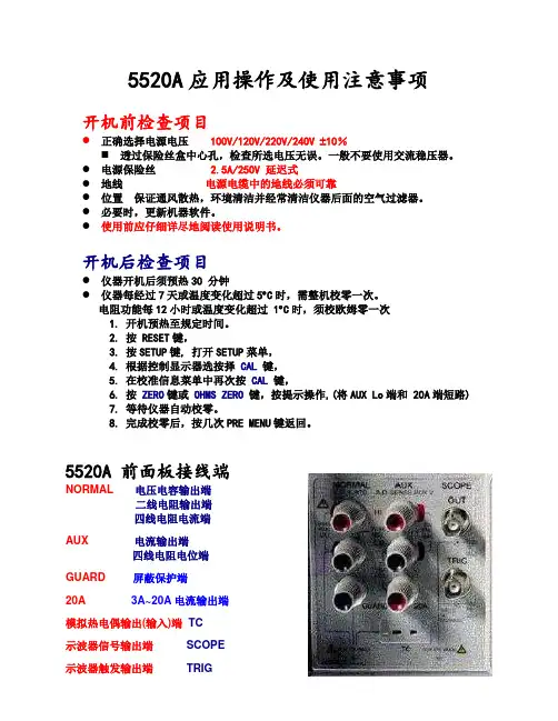
5520A应用操作及使用注意事项开机前检查项目●正确选择电源电压100V/120V/220V/240V ±10%⏹透过保险丝盒中心孔,检查所选电压无误。
一般不要使用交流稳压器。
●电源保险丝 2.5A/250V 延迟式●地线电源电缆中的地线必须可靠●位置保证通风散热,环境清洁并经常清洁仪器后面的空气过滤器。
●必要时,更新机器软件。
●使用前应仔细详尽地阅读使用说明书。
开机后检查项目●仪器开机后须预热30 分钟●仪器每经过7天或温度变化超过5︒C时,需整机校零一次。
电阻功能每12小时或温度变化超过 1︒C时,须校欧姆零一次1. 开机预热至规定时间。
2. 按 RESET键,3. 按SETUP键, 打开SETUP菜单,4. 根据控制显示器选按择CAL键,5. 在校准信息菜单中再次按CAL 键,6. 按ZERO键或 OHMS ZERO键,按提示操作,(将AUX Lo端和 20A端短路)7. 等待仪器自动校零。
8. 完成校零后,按几次PRE MENU键返回。
5520A 前面板接线端NORMAL电压电容输出端二线电阻输出端四线电阻电流端AUX 电流输出端四线电阻电位端GUARD屏蔽保护端20A 3A~20A电流输出端模拟热电偶输出(输入)端TC示波器信号输出端SCOPE示波器触发输出端TRIG电压功能设置和连接●用NORMAL HI端和 LO端输出电压●先输入电压数值,●选择极性+/-●按倍数键m k M●按V键●再输入频率值●按倍数键m k M●按Hz键●按ENTER键入值有效●按OPR键输出❖输出直流毫伏电压时至低输入阻抗仪表时,应选用3.3V量程,锁定量程直接输出。
❖电压从低至高输出超过33V时,需确认安全重新按下OPR键后,才能输出。
输出电压大于100V时,有蜂鸣声提醒注意安全。
❖发生输出保护时,不可强行接通。
检查无误并经过若干秒后,方可再接通。
❖5520A输出端不可接入外部电源信号。
电流功能设置和连接●用AUX HI 端和 LO 端输出电流●先输入电数流值,●选择极性+/-●按倍数键m k M●按A键●再输入频率值●按倍数键m k M●按Hz键●按ENTER键●按OPR键输出❖当驱动模拟式交流电流表时,应在右侧控制显示器中选择 LCOMP(电感补偿)。
贝尔日常维护流程及常用指令贝尔日常维护流程及常用指令第一部分:贝尔例行维护操作 (2)1.1每日例行工作 (2)1.2每周例行工作 (2)1.3每月例行工作 (4)1.4每季度例行工作 (5)第二部分:贝尔设备故障处理 (9)2.1 链路告警 (9)2.2 安全块告警 (10)第三部分:一些有用的指令和MARCO (11)第一部分:贝尔例行维护操作1.1每日例行工作1.1.1控制室环境卫生、终端及其它外设检查机房环境和设备清洁卫生1.1.2机房温湿度检查检查机房内的温湿度表,正常的温度应该是23℃±2℃,湿度应该是40%-60%;1.1.3七号信令告警显示及处理用指令>MM<19:OPTION=ALL.如果19命令显示有CCLK、CCLD等告警,则用7599命令看告警详细内容。
>MM<7599:OPTION=LINK,LKID=ALL.检查,看到的为信令链告警;<7599:OPTION=LKSET,LKSET=ALL.检查,看到的为链路集告警;<7599:OPTION=DEST,DEST=ALL,LOGNET=ALL.检查,看到的为DEST不可达告警。
1.1.4信令链路情况显示及处理根据上步7599命令显示,用>MM<241:LKID=BB,DETAIL=SWSTAT.查看链路状态及链路配置;根据状态显示对不正常链路做出相应处理(详细处理过程见第二部分贝尔故障处理)1.1.5信令路由情况显示及处理用指令>MM<250:RTESID=CC,DETAIL=1.检查信令路由状态,如果路由不可用:直达路由,与链路不正常处理一样,非直达路由,A-TFP代表中间的STP到目的地的路由不可用。
AV代表正常,无话务;TRF代表正常有话务。
UNAV NONE 代表操作设置不可用。
1.1.6设备告警显示及处理用指令<display-active-alarms.(命令号:19),如果19显示有安全块告警,用< p="">D: I:两个宏对安全块进行闭解操作。
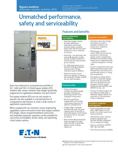
1 M anual operation (unloaded) provided for all product configurations; manual operation (under load)available for select catalog configurations.2 Feature/rating available for select catalog configurations.Unmatched performance, safety and serviceabilityProven performance and reliability•Automatic bypass switch provides operational redundancy and quickly restores power to criticalloads when the ATS has been isolated for test or removed for service•Automatic, non-automatic and manual A operation modes provide multiple methods of transferring the load between power sources•UL 1008 listed short-circuit and short-time B withstand closing current ratingsmaximize system reliability •Tethered remote controlallows an operator to initiate a non-automatic transfer outside the arc flash boundaryEnhanced safety•Unique three-door,compartmentalized design provides steel barriers protecting workers from energized components •All doors open/closeindependently eliminating unnecessary exposure to adjacent compartments •Integral safety interlocks automatically open the main contacts prior to the ATS or automatic bypass switch being isolated for test or removed for service•Rear shutters B automatically close to isolate bus stabs when the ATS or automatic bypass switch is being racked outEaton has enhanced its comprehensive portfolio of UL T 1008 and CSA 178 listed bypass isolation ATSsolutions with power contactor type designs specifically engineered for applications between 100 and 3000 A.Our bypass isolation ATSs are not only simple to operate, but also available in a broad selection of configurations and features to meet a wide variety of application requirements.When coupled with our extensive custom engineering capabilities, Eaton’s innovative three-door bypass isolation ATS design, robust compartmentalized construction, and redundant automatic operation set the standard for concurrent serviceability, worker safety, and optimizing critical system uptime.Improved serviceability•Innovative three-door design eliminates the need to schedule shutdowns for routine test, inspection or maintenance•Maintenance isolationswitch (MIS) permits service personnel to electricallyisolate control compartment elements and minimize shock hazard prior to beginning work —without disruption to critical loads•Control compartment door and adjoining electrical panel slide forward from the enclosure to provide easy access to wiring and components•Dual drawout design allows the ATS or automatic bypass switch to be disconnected from the electrical bus and isolated in cell for regular testing as prescribed by code (NFPA T 70, 99, 110)•Testing of isolated switch can be performed while ATS or automatic bypass switch is in automatic or non-automatic mode of operationSimplified installation and integration•Field-configurable terminals allow cable ingress at top/bottom for power source and load connections•Internal floor-mount anchors minimize footprint andfacilitate efficient integration into an equipment lineup •Seismic certified to OSHPD,CBC, IBC and UBC•Front and rear access availableFeatures and benefitsBypass isolationContactor type, 100–3000 AOpen/closed transitionDesign featuresDual automatic technologyEaton’s unique design includes an automatic bypass switch and an ATS within a single assembly to provide redundant automatic operation and uninterrupted power to critical loads.Optimize reliability and maximize uptimeThe automatic bypass switch and ATS can be racked out and isolated in cell for regular testing to ensure the entire bypass isolation transfer switch is maintained in proper operating condition.Facilitate scheduled maintenance The automatic bypass switch or ATS can be withdrawn for visual inspection andcompletely removed for bench testing without impacting automatic operation.Enhance worker safetyThe upper and lower doors can be operated independently, maintaining electrical isolation of the energized compartment.T esting… it’s as easy as 1-2-3 A three-step operator interface helps simplify testing procedures of the automatic bypass switch or ATS when racked out to the isolated position.Safe and serviceableEngineered for safety, athree-door compartmentalized construction coupled with an MIS allow personnel to perform maintenance on the bypass isolation transfer switch while energized.To mitigate shock hazard, the MIS can be placed in the maintenance position prior to opening the door, electrically isolating elements of the control compartment from system and control voltage.Once isolated, the control compartment door can beopened and adjoining electrical panel slid forward, allowing a technician to safely inspect, troubleshoot and replace electrical components.Upon completion, the door is closed and MIS returned to the normal operation position.Multiple operation modes Local operation is possible in the following modes:•Automatic •Non-automatic •Manual AIn Automatic mode, the transfer switch is self-acting, and atransfer is automatically initiated by the intelligent controller logic.In Non-Automatic mode, a transfer is initiated by theoperator using a door-mounted selector switch or an optional tethered remote control.In Manual mode, a transfer is initiated by the operator using controls mounted directly on the automatic bypass switch or ATS.Alternatively, a transfer can be initiated remotely via an HMi remote annunciator controller or network communication.Automatic bypass switch With the upper door open, operators can draw out the automatic bypass switch for inspection or maintenance.With the upper door closed, operators can rack out, isolate and test the automatic bypass switch in cell.Automatic transfer switch With the lower door open,operators can draw out the ATS for inspection or maintenance. With the lower door closed, operators can rack out, isolate and test the ATS in cell.Control compartment door and adjoining electrical panel slide forward.MIS provides ability to electrically isolate control compartment elements prior to start of maintenance.Safe, easy and spacious access to wiring and components.Electrical load remains connected to power during maintenance procedures.Featuring simplified testing procedures for the ATS and automatic bypass switchT ethered remote control for non-automatic operationA Manual operation (unloaded) provided for all product configurations;manual operation (under load) available for select catalog configurations.2EATON Bypass isolation automatic transfer switches (ATS)Product selectionCatalog numbering systemTechnical specificationsA Check with your local Eaton sales representative for NEMA 12 and NEMA 4X enclosure specifications. NEMA 3R stainless steel available upon request.B Dimensions in inches (mm) and weight in lb (kg). Data is approximate, subject to change, and representative of a typical product configuration.Please reference product outline drawing(s) for latest information. Custom-engineered enclosure options available upon request.A Standard mechanical lugs are UL listed, solderless screw-type Cu/Al. Number of conductors and size range shown is per pole and representative of typical product configuration.B Two-hole compression lug or bus connect provisions available upon request. Please contact your local Eaton sales representative for more details.C Only applies to wye system configuration with solid neutral. For four-pole (switched neutral) configurations, the number and size of conductors supported will mimic the Normal,Emergency and Load terminal information shown.ote: N Some catalog number combinations may not be available. For additional information, please contact your local Eaton sales representative.3EATON Bypass isolation automatic transfer switches (ATS)UL 1008 listed withstand closing current ratingsATC-900—intelligent controlEaton’s ATC-900 controller brings ease of use, adaptability, supervisory and programming capabilities to mission-criticalapplications. The 4.3-inch color TFT display provides simple arrow keys for quick screen navigation and easy viewing of event logs as well as recorded time-stamped events. Field configuration of programmable I/O allows user adaptability to special requirements.1Time duration is 0.13 sec. maximum.4EATON Bypass isolation automatic transfer switches (ATS)Eaton is a registered trademark.All other trademarks are property of their respective owners.Eaton5050 Mainway Burlington, Ontario L7L 5Z1 CanadaEatonCanada.ca© 2020 EatonAll Rights Reserved Printed in CanadaPublication No. PA140014EN October 2021HMi remote annunciator controllerEvolving arc flash regulations and requirements for personal protective equipment are driving more and more end users toward the use of remote monitoring and control devices. Eaton’s HMi remote annunciator controller offers a simple and cost-effective means of managing up to eight ATSs via serial or ethernet communication.In many cases, standard products can be custom-order engineered to meet unique application needs. For additional information, please contact your local Eaton sales representative.Custom-order engineeringRemote annunciator controllerT /bypassATSFollow us on social media to get the latest product and support information.。

网管U2020操作指导书(总37页)--本页仅作为文档封面,使用时请直接删除即可----内页可以根据需求调整合适字体及大小--连接内网需将IP设为动态模式,关闭其它代理谷歌浏览器输入网管地址:,不安装网管部分功能无法使用)一、MML命令窗口:常用命令:LST NRCELL 查询NR小区静态参数(频带,下行频点,双工模式,激活状态DSP NRCELL 查询NR小区动态参数(最近一次NR DU小区状态变化的原因等)LST NRDUCELL 查询NR DU小区静态参数(小区标识、PCI、带宽、频点等)DSP NRDUCELL 查询NR DU小区动态参数LST GNODEBFUNCTION查询gNodeB功能(基站号)LST ALMAF 查询活动告警LST NRCELLRESELCONFIG 查询NR小区重选配置(部分网元版本不支持)LST NRCELLRELATION 查询NR小区关系LST NRDUCELLPDSCH 查询NR DU小区PDSCH配置LST NRDUCELLPUSCH:; 查询NR DU小区PUSCH配置DSP GNBCUX2LST NRCELLRELATION 查询NR小区邻区LST NREXTERNALNCEL 查询NR外部邻区LST NRCELLANR 查询NR小区ANRLST NRCELLEUTRANRELATION 查询NR小区E-UTRAN邻区关系LST GNBEUTRAEXTERNALCELL 查询gNodeB EUTRAN外部小区LST NRCELLEUTRANNFREQ 查询NR小区E-UTRAN相邻频点LST OPTLOG 查询操作日志LST RRU 查询RRU配置信息(5G站点RRU为AAU),根据发射通道和接受通道个数可知小区为64T64RSTR NRDUCELLCHNCALIB 启动NR DU小区通道校正DSP NRDUCELLCHNCALIB 查询NR DU小区通道校正,通道校正通过才能进行单验STR VSWRTEST 启动驻波比测试STP VSWRTEST 停止驻波比测试1)当驻波比大于工程质量要求值时,说明连接存在问题,需要检查天馈连线和天馈设备;2)DSP VSWR查询的驻波值是射频模块使用当前运行功率来启动自动驻波测试结果,而STR VSWRTEST是根据单音以最大功率启动驻波测试,并且两种测试精度不同,因此二者结果会有差异3)该命令依次对每个发射通道进行串行测试,因此执行时间会随发射通道的个数成倍增加DSP BRD 查询单板 (5G的单板为AIRU)LST NRCELLALGOSWITCH 查询NR小区级算法开关LST NRDUCELLALGOSWITCH 查询NR DU小区算法开关(可修改“上行非连续调度LST NRDUCELLTRP 查询NR DU小区TRP(功率),目前最高349dBm(200W)NRDUCELLTRPID=201,MAXTRANSMITPOWER=349;(修改发射功率)LST GNODEBPARAM gNodeB下所有小区空口帧的起始相对于参考时钟源的延迟时间(用于5G站点与TDD站的帧对齐)ACT NRDUCELL 激活ACT NRCELL 激活NSA组网模式下,5G小区需同时激活FDD锚点站、5G小区、5G DU小区,才可将站点完全激活使用户接入DEA NRDUCELL 去激活DEA NRCELL 去激活RMV 删除ADD 添加DSP ALLUEBASICINFO 查询LTE小区下所有UE(User Equipment)的基本信息DSP GNBCUX2INTERFACE 查询gNodeB CU X2接口状态和信息LST SCTPHOST查询SCTP本端配置信息查询5G站PDCP分流模式,避免影响现网,将服务质量等级8和9的“AM模式PDCP参数组标识”设置为5;将参数组5的“下行数据PDCP分流模式 = 动态分流”设置为仅向辅站分流LST NRCELLQCIBEARERLST GNBPDCPPARAMGROUP锚点站A6主控板不支持NSA组网模式锚点站主控板查询:锚点站主控板型号:WD22UMPTe3运营商信息查询(MCC、MNC)组网配置 LST GNBOPERATOR(5G) LST CNOPERATOR(4G)FDD站点关闭ANR功能MOD CELLALGOSWITCH 小区级算法开关,MOCN改造站的关闭ANR开关锚点站关闭DRX MOD CELLDRXPARA:LOCALCELLID=1,DRXALGSWITCH=OFF;TAC查询:5G站点LST GNBTRACKINGAREA:; 4G站点 LST CNOPERATORTA:;查询gNodeB测量公共参数组 LST GNBMEASCOMMPARAMGRPLST ALMLOG 查询告警日志LST CELLRESEL 查询小区重选信息调整优先级,小区重选门限等LST CELLMCPARA 查询测量控制参数信息LST NRDUCELLRSVDPARAM:;保留参数15,小区频选开关,接入信号强度最高的小区,其它信号对本小区的干扰影响,应用于n41频段开通100M后,避免周边D1\D2的干扰影响软件版本批量导出:LST RETPORT 传输口查询LST GNBCIPHERCAPB:; gNodeB加密算法优先级TUE保障通过关闭加密算法,速率可以进一步提升。
上海贝尔SAM网管使用手册收录整理:陈鹏1基站基本操作:SOC:板卡SDCAMlegacy:板卡eCCM2 +BCEM1845的RRH功耗:445瓦适应空开:16安培Legacy的BBU:620瓦(1ECM2 +3 BCEM)适应熔丝:16安培/20安培SOC的BBU:250瓦(1块BCEM2)1.1 开站问题1.1.1请问在导版本的时候提示“连接被拒绝”这个问题该如何解决?关掉防火墙之类的东西试试(360安全卫士/QQ管家之类的)1.1.2检查I2C连接情况:(注意:命令在sclish模式下执行)排查C板传输光口是否正常,failed是不正常的,succeed是正常的.(执行命令如下图)1.1.3SOC的设备开完站遇到GPS故障的,编辑WO查找gpsClockEnable,把里面的true改成false1.1.4开站光模块识别:传输使用的光模块RRH使用的双芯光模块(其中有6G的和9.8G的),还有1.4KM和10KM 的距离分别,根据现场需要进行适配.单芯光模块使用方法:1.1.5如何备份database打开secureCRT软件(在root权限下进行)进入database的目录下面:cd /data/db/active/mim将database的文件复制到/home/enb0xfer :cp database.xml /home/enb0xfer查看是否拷贝成功:cd /home/enboxfer 查看: ls查看是否存在databse.xml 文件存在继续下面操作、不存在重新执行上面命令修改文件权限:chmod enb0xfer database.xml (需要回车的)使用FileZilla软件下载:本地连接IP:192.168.2.1 网管对基站:基站IP即可(用户名/密码:enb0xfer/&65UytJhg)进入home/enboxfer 目录下载即可.(备份完成)1.1.6板卡S1不通,现场核查办法:1、与传输确认传输模式(自适应还是强制签到),我们eCCM2板卡只能支持强制签到模式,ECCM-U板卡都能支持.2、检查规划数据与database数据是否一致.(在NEM查看IP地址)eCCM2-root-root> ifconfigeth0 Link encap:Ethernet HWaddr 18:4A:6F:4B:0F:77inet6 addr: fe80::1a4a:6fff:fe4b:f77/64 Scope:LinkUP BROADCAST RUNNING MULTICAST MTU:2000 Metric:1RX packets:430667 errors:0 dropped:0 overruns:0 frame:0TX packets:424480 errors:0 dropped:0 overruns:0 carrier:0collisions:0 txqueuelen:1000RX bytes:48932078 (46.6 MiB) TX bytes:49651842 (47.3 MiB)Memory:fe5e0000-fe5e0fffeth0.200 Link encap:Ethernet HWaddr 18:4A:6F:4B:0F:77inet addr:10.105.107.226 Bcast:10.105.107.227 Mask:255.255.255.252 (核查IP地址)UP BROADCAST RUNNING MULTICAST MTU:1500 Metric:1RX packets:363040 errors:0 dropped:0 overruns:0 frame:0TX packets:357868 errors:0 dropped:0 overruns:0 carrier:0collisions:0 txqueuelen:0RX bytes:31576334 (30.1 MiB) TX bytes:31818524 (30.3 MiB)eth0.300 Link encap:Ethernet HWaddr 18:4A:6F:4B:0F:77inet addr:10.105.235.226 Bcast:10.105.235.227 Mask:255.255.255.252 (核查IP地址)UP BROADCAST RUNNING MULTICAST MTU:1500 Metric:1RX packets:67617 errors:0 dropped:0 overruns:0 frame:0TX packets:66606 errors:0 dropped:0 overruns:0 carrier:0collisions:0 txqueuelen:0RX bytes:11324790 (10.7 MiB) TX bytes:17832850 (17.0 MiB)eth2 Link encap:Ethernet HWaddr 18:4A:6F:4B:0F:79inet addr:192.168.10.1 Bcast:192.168.10.255 Mask:255.255.255.0inet6 addr: fe80::1a4a:6fff:fe4b:f79/64 Scope:LinkUP BROADCAST RUNNING MULTICAST MTU:1500 Metric:1RX packets:0 errors:0 dropped:0 overruns:0 frame:0TX packets:6 errors:0 dropped:0 overruns:0 carrier:0collisions:0 txqueuelen:1000RX bytes:0 (0.0 B) TX bytes:468 (468.0 B)Memory:fe5e4000-fe5e4fffeth3 Link encap:Ethernet HWaddr 18:4A:6F:4B:0F:7Ainet addr:192.168.1.2 Bcast:192.168.255.255 Mask:255.255.0.0inet6 addr: fe80::1a4a:6fff:fe4b:f7a/64 Scope:LinkUP BROADCAST RUNNING MULTICAST MTU:1500 Metric:1RX packets:1136780 errors:0 dropped:0 overruns:0 frame:0TX packets:504287 errors:0 dropped:0 overruns:0 carrier:0collisions:0 txqueuelen:1000RX bytes:596324345 (568.6 MiB) TX bytes:45330298 (43.2 MiB)Memory:fe5e6000-fe5e6ffflo Link encap:Local Loopbackinet addr:127.0.0.1 Mask:255.0.0.0inet6 addr: ::1/128 Scope:HostUP LOOPBACK RUNNING MTU:16436 Metric:1RX packets:337634 errors:0 dropped:0 overruns:0 frame:0TX packets:337634 errors:0 dropped:0 overruns:0 carrier:0collisions:0 txqueuelen:0RX bytes:92259214 (87.9 MiB) TX bytes:92259214 (87.9 MiB)tap0 Link encap:Ethernet HWaddr 02:EC:C8:94:E3:30inet6 addr: fe80::ec:c8ff:fe94:e330/64 Scope:LinkUP BROADCAST RUNNING MULTICAST MTU:1500 Metric:1RX packets:0 errors:0 dropped:0 overruns:0 frame:0TX packets:0 errors:0 dropped:0 overruns:0 carrier:0collisions:0 txqueuelen:500RX bytes:0 (0.0 B) TX bytes:0 (0.0 B)eCCM2-root-root> routeKernel IP routing tableDestination Gateway Genmask Flags Metric Ref Use Iface10.105.107.224 * 255.255.255.252 U 0 0 0 eth0.200 (网关地址)核查10.105.235.224 * 255.255.255.252 U 0 0 0 eth0.300 (网关地址)核查192.168.10.0 * 255.255.255.0 U 0 0 0 eth2192.168.0.0 * 255.255.0.0 U 0 0 0 eth3127.0.0.0 * 255.0.0.0 U 0 0 0 lodefault 10.105.235.225 0.0.0.0 UG 0 0 0 eth0.300 eCCM2-root-root>业务地址通的,管理地址不同(协调传输)1.1.7如何从NEM上查看SFP信息以上图为例,SFP 1-40-1表示C板上的SFP信息,Unit Position表示SFP所在的位置。
光纤自动切换保护系统网管操作手册北京中昱光通科技有限公司Beijing ZhongYu Optical Communication Technologies Co., Ltd . ZYOCOPTICAL AUTO SWITCH NETWORK SYSTEM目录1. 运行环境 (3)1.1硬件环境 (3)1.2软件环境 (3)2. 主要功能 (3)2.1系统概述 (3)2.2强大的管理功能 (4)2.3光纤功率监测功能 (4)2.4短信告警功能 (4)2.5光纤路由切换保护功能 (4)3. 用户管理 (4)3.1用户登录 (4)3.2用户管理 (5)3.3密码修改 (5)4. 光功率监测 (6)4.1简介 (6)4.2操作说明 (6)5. 路由切换 (8)5.1简介 (8)5.2设置说明 (8)5.3切换路由 (9)6. 线路管理 (10)6.1简介 (10)6.2设置说明 (10)6.3添加传输系统 (11)6.4路由切换 (12)7. 短信功能 (13)7.1简介 (13)7.2告警短信 (13)7.2.1切换告警 (13)7.2.2光功率告警短信 (14)5.2.3光源关闭短信 (14)7.2.4工作状态短信 (14)7.2.5网络状态短信 (14)8. 告警管理 (15)8.1告警日志 (15)8.2当前告警 (15)8.3告警音管理 (16)9. 通信设置 (17)10. 数据维护 (18)10.1添加地区 (18)10.2添加局站 (19)10.3添加机箱 (19)10.4添加保护卡 (20)10.5建立和取消镜象关系 (20)10.6添加全程缆 (22)10.7添加光缆段 (22)10.8连接光纤 (23)11. 统计测试 (25)11.1光功率历史记录 (25)11.1.1历史曲线图 (25)11.1.2数据分析 (26)11.2静态资源统计 (26)11.3镜象统计 (27)12. 网络拓扑结构图 (27)12.1添加局站 (27)12.2拓扑图分析 (28)12.3拓扑图中切换路由 (29)12.4拓扑图参数设置 (29)13. 电源管理 (30)14. 其它软件 (31)14.1通信服务器 (31)14.2短信息发送服务器 (31)14.3EDFA网管中心.................................................................................. 错误!未定义书签。
上海贝尔7360 OLT手动开通ONU步骤1、通过TL1方式登录OLT,查看是否有新LOID上报至OLT先TELNET上网管telnet 134.207.16.82用户名:root密码:5520AMS@QZ-DX再TELNET上OLT,如10.107.31.6端口1023telnet 10.107.31.6 1023 //134.207.16.82为OLT的IP地址,后面加1023端口号按一下回车键,弹出以下提示,选TWould you like a TL1 login(T) or TL1 normal session(N) ? [N]:T输入帐号密码登录:Enter Username :SUPERUSER //注意:用户名和密码都是大写Enter Password :ANS#150<RTRV-ALM-ALL; //查看告警,可以看到是否有新的ONU接上来IP 0"PON-1-1-1-2,PON:MN,NEWONT,NSA,,,,,://从第1槽的第2个PON口发现新的ONU\"SERNUM = ALCLF8AE75F7, SLID =0001684291 , LOID=0777444444999999\"";2、如何在OLT创建一个FTTH终端登录北向telnet 134.207.16.82 12015 // 12015为北向端口telnet进去以后,登录命令如下:LOGIN:::CTAG::UN=manager,PWD=123456;增加ONU://红色字体为需要根据实际情况更改的参数ADD-ONU::OLTID=134.207.16.82,PONID=1-1-1-2:CTAG::AUTHTYPE=LOID,ONUID=0777444444999999,ONUTYPE=E8-C;ADD-PONVLAN::OLTID=134.207.16.82,PONID=1-1-1-2,ONUIDTYPE=LOID,ONUID=0777444444999999:CTAG::CVLAN=201,SVLAN=2312,UV =41; (注意GPON网管的SVLAN是一块板一个,如何知道SVLAN是多少?后续会有命令再看)ADD-PONVLAN::OLTID=134.207.16.82,PONID=1-1-1-2,ONUIDTYPE=LOID,ONUID=0777444444999999:CTAG::CVLAN=45,SVLAN=2312,UV= 45;ADD-PONVLAN::OLTID=134.207.16.82,PONID=1-1-1-2,ONUIDTYPE=LOID,ONUID=0777444444999999:CTAG::CVLAN=46,SVLAN=2312,UV= 46;如何删除ONU,也是通过北向接口进行删除:DEL-ONU::OLTID=134.207.16.82,PONID=1-1-1-2:CTAG::ONUIDTYPE=LOID,ONUID=0777444444999999;退出LOGOUT:::CTAG::;3、如何查看注册的终端是否正常在线通过CLI方式登录OLT,查看新建ONU的注册状态和业务是否正常telnet 134.207.16.82 //134.207.16.82为OLT的IP地址,无需加端口号用户名:root密码:5520AMS@QZ-DX再TELNET上OLT,如10.107.31.6login:isadmin //注意:用户名和密码都是小写password:ans#150typ:isadmin>#info configure equipment ont //检索新创的ONU的接口编号configure equipment#----------------------------------------------------------------------------------echo "equipment"#----------------------------------------------------------------------------------ontinterface1/1/1/2/1sw-ver-pland 3FE53862AOCI76sernum ALCL:F8AE75F7subslocid WILDCARDvoip-allowed enablelog-auth-id0777444444999999//检索到新创ONU的接口编号为1/1/1/2/1admin-state upexitslot 1/1/1/2/1/1 planned-card-type 10_100base plndnumdataports 4 plndnumvoiceports 0exitexit#----------------------------------------------------------------------------------leg:isadmin>#show interface port ont:1/1/1/2/1 //查看新创ONU的状态===================================================================== ==============port table================================================================= ==================port|admin-status|opr-status---------------------------------------------------+------------+------------------ont:1/1/1/2/1 upup//注册成功-----------------------------------------------------------------------------------port count : 1leg:isadmin>#show vlan bridge-port-fdb //查看ONU业务是否正常================================================================= ==================bridge-port-fdb table================================================================= ==================port |vlan-id |mac|fdb-id |status|vmac-------------------+-----------------+-----------------+-----------------+-------+-1/1/1/2/1/1/14100:19:c7:e9:24:a6 stacked:2312:0 learned00:00:00:00:00:001/1/1/2/1/1/14600:19:c7:e9:24:a5 stacked:2312:0learned00:00:00:00:00:00//41和46VLAN都能正常学习到MAC地址,说明业务正常-----------------------------------------------------------------------------------bridge-port-fdb count : 23、如何查看一块光板配置的SVLAN是多少?telnet 134.207.16.82 //134.207.16.82为OLT的IP地址,无需加端口号用户名:root密码:5520AMS@QZ-DX再TELNET上OLT,如10.107.31.6login:isadmin //注意:用户名和密码都是小写password:ans#150typ:isadmin># info configure service---------------------------------------------- customer 1 createdescription "Default customer"exities 1 customer 1 createinterface "OAM" createaddress 10.107.31.6/24sap nt:vp:1:2001 createexitexitno shutdownexitvpls 2 customer 1 v-vpls vlan 2001 create stpshutdownexitsap nt-a:eth:1:0 createexitsap nt-a:xfp:1:2001 createexitno shutdownexitvpls 2601 customer 1 v-vpls vlan 2601 createstpshutdownexitsap nt-a:xfp:1:2601 createexitsap lt:1/1/1:2601 create 1槽位光板的SVLAN为2601exitno shutdownexitvpls 2602 customer 1 v-vpls vlan 2602 createstpshutdownexitsap nt-a:xfp:1:2602 createexitsap lt:1/1/2:2602 create 2槽位的SVLAN为2602exit4、如何查看FTTH配置的业务VLAN是否配置:telnet 134.207.16.82 //134.207.16.82为OLT的IP地址,无需加端口号用户名:root密码:5520AMS@QZ-DX再TELNET上OLT,如10.107.31.6login:isadmin //注意:用户名和密码都是小写password:ans#150typ:isadmin># info configure bridge port 1/1/1/8/1/1/1(1槽8光口,ONTID=1)configure bridge#-----------------------------------------------------------echo "bridge"#-----------------------------------------------------------port 1/1/1/8/1/1/1max-unicast-mac 16vlan-id 41network-vlan stacked:2601:300vlan-scope localexitvlan-id 45network-vlan stacked:2601:45vlan-scope localexitvlan-id 46network-vlan stacked:2601:46vlan-scope localexitexit#----------------------------------------------------------- typ:isadmin>#。
AMS5520网管简易操作文档
1.启动客户端,登录ams5520
点击客户端文件夹中的可执行文件amsclient.exe或提前配置好的桌面快捷方式打开客户端程序
出现登录界面,如下:
依次输入网管server的ip地址,用户名:admin,密码:admin,点击完成以后登录
(注:新装第一次登入会提示更改默认密码admin。
成功登录过一次以后,下次登录时,会自动显示上次登录server的主机名,不必再次输入ip地址)
出现如下提示则登录成功
2.修改用户配置和创建新用户
点击管理界面
(1)参照如下图修改用户配置
输入两次新密码,可以更改登录密码
修改最大并发数,最大并发数指的是最多允许多少个客户端使用这个账号同时登录点击右上角的打钩确认
(2)创建新用户
点击创建用户,出现如下界面
输入用户名,点击next出现如下界面
配置密码用户名和最大并发数
3.分权分域的配置方法
我们现在需要新建一个网元组group2,管理不同区域的网元,并且使test账号只能管理到新建的组
我们要使test账号智能管理到group2则需要做如下操作创建pap
出现如下界面:
输入分组名称后点击finish 然后创建pap组
出现如下界面
输入名称后点击next
把刚才创建的pap222和用户名test添加到组中,使test账号能管理到pap222的分组然后配置和确认test用户的权限和分组
创建新的网元组group2
写入名称,更改到刚才创建的pap组
点击finish以后,使用test账号登陆可以看到test账号只能管理到group2
4.添加和管理网元
右击group2项,选择创建网元
选择网元类型和版本,7360设备选择7360 ISAM R4.3 IHUB,点击next
按下图填写网元名称,网元ip,选择SNMP配置模板,输入CLI用户名密码,输入TL1用户名密码,选择外部TL1网关服务,点击finish
右击网元图标打开菜单,启动网元监控
网元上的图标箭头向上表示成功管理上
5配置olt下挂的onu业务5.1查看OLT基本信息
双击网元图标
看到机架
双击机架图标看到具体的板卡
可以看到有第1到第5槽位的用户板是正在使用的,NTA槽位的主控板也在使用中
5.2 OLT基本操作
板卡操作
选中需要操作的板卡右击,动作菜单内选择规划和撤销,就是创建和删除板卡,重启就是重启板卡,选择加电,掉电就lock、unlock板卡。
Pon口操作
选中需要操作的pon口,可以关闭和打开pon口
在左边每个网元的树状结构中可以看到olt上的vlan信息
通过网管5520创建S+CV ALN,分两步操作,先创建SV ALN,再创建S+CVLAN.
点击Finish。
SVLAN创建成功。
点击Finish。
S+CV ALN创建完成。
这时能在左边能看看创建的VLAN了,
配置网络侧SVLAN:
6.添加ONT
注意:端口绑定VLAN时,记得把上行带宽绑定。
7.5520上添加终端硬件信息:
7.5520设置定时采集
8.5520下载终端软件到OLT
9.注意事项
(1)Olt网元需要被网管管理上的话,需要做如下命令
configure system security snmp community public host-address 0.0.0.0/0 privilege read-write
configure system security snmp community NETMAN host-address 0.0.0.0/0 context ihub
(2)客户端不能登录时请检查用户名密码是否正确,检查网管服务器的地址是否畅通?如果都没有问题,再检查5520进程是否都已UP?。