ASHLY324中文使用手册
- 格式:pdf
- 大小:458.44 KB
- 文档页数:14

FX 500 Front PanelFX 60 and FX 125 Front PanelThe FX series is a range of multi-purpose installationDSP-equipped amplifiers. The FX series amplifiers feature a built-in Wireless-Access-Point (WAP) for simple connection and configuration via WiFi as a well as an intuitive web-based software UI. With 6 models to choose from starting at 2 x 60W in a half rack unit to 4 x 500W in a two rack unit, there’s an FX that will fit just about any project.Naturally, they have the rugged reliability that Ashly is known for…including a 5-year warranty.TECHNICALSPECSonPAGE FOURFX SeriesDSP Power A mplifiers with intuitive web-based software UI and built-in WiFi for convenient connectivity and configuration.❚Conference/Huddle Rooms ❚Classrooms ❚Retail Stores ❚Hotel Lobbies❚Inside Displays & Kiosks ❚Bars and Restaurants ❚Trade Show Exhibits ❚HoW & AuditoriumsFX 60 and FX 125 Front PanelFX 500 Front PanelFX 500.2 – Back FX 500.4 – Back – Amplifier operational.– Standby Mode.– GPIO triggered Standby Mode– No input signal present.– Signal present on one or more inputs.– Signal limiting/clipping on one or more inputs.Off – No output signal present.Green – Signal present on one or more outputs.Amber – Signal limiting/clipping on one or more outputs.Red – One or more channel pair is in overload/protection mode.4-Channel Models– WiFi disabled. – WiFi enabled– No Ethernet network detected. – Network enabled– Ethernet network detected.AnalogAnalog AC receptacle100-240VAC 50/60HzInput/Output 2-Channel ModelsEach FX model offers a healthy compliment of IO (include Digital SPDIF In & Out) and programmable integration ports for remote Volume Control, GP triggers and more.FX is networkable via Ethernet for wired LAN connection, or via its built-in WiFi hotspot. FX allows system configurations that don’t require additional equipment, such as stand-alone DSP or speaker system processors. All of that is in one box.Page 3 of 4FX SeriesHigh-Density DSP Power AmplifiersIntelligent DSPTo control FX’s powerful DSP, you’ll find easy access to its intuitive and user-friendly interface via a simple web browser (similar to AquaControl). No software to install (it’s built into the FX unit).Just connect using the Ethernet port or built-in WiFi and you’re ready to Rock & Roll. The WiFi connection allows secure ID and password protection from unauthorized use and for more advanced users, Ethernet allows custom IP settings for use on a more complex wired LAN.The FX Series features a powerful DSP engine that canconfigure to suit virtually any task, without the need for additional equipment. From processing input sources, routing and output DSP that can fine tune the sound of any speaker. Everything you need is right there. These will mixinto Zones A-D and then into Outputs (2 or 4 depending on the number of amplifier channels). All models have a 4-channel DSP configuration with Input processing, Zone Processing, Output Processing, Speaker Processing and Device SettingsAnalog 3Analog 2Analog 1Analog 4SPDIF (stereo)Input Setupgn i t u o R & p u t e S e n o Z Output SetupOutput 1Output 2Output 3Output 4sr e t e m a r a P t n e m t s u j d A m o o R sr e t e m a r a P t n e m t s u j d A r e k a e p S Four-Channel models onlyIntuitive Software UIBrowser-based control from any deviceFA1.2RPM – 1 or 2-amp rack-mount kitFA2.2RPM – Rear rack support kitAshly Audio, Inc. • 847 Holt Road • Webster, NYUSA • US toll-free +1.585.872.0010 Fax +1.585.872.0739•***************©2019-2022 Ashly Audio A Division of JAM Industries USA, LLC. All Rights Reserved. Ashly is a registered trademark. Any other trademarks are property of their respective holders.All Specifications are subject to change.FX_DS_v01.1FX SERIES ARCHITECT & ENGINEERING SPECIFICATIONSin .txt format are available in the DOWNLOADS section of FX SERIES2D AUTOCAD FILES are available in the DOWNLOADS section of https://bit.ly/3ppPEvUDownload the full FX User Manual at https://bit.ly/3GL73FdUSER MANUALOptional Rack Mounts (For half rack models)1) N ote:*100V line mode operates @ -1 dB (≈ 90 V)**FX125.4 and FX 500.4 may only Powershare across Ch1/2 and Ch3/4 Country Of Origin (COO): FX60.x and 125.x is China and FX 500.x is Thailand。
All Rights Reserved r 0611KLR-Series AmplifiersKLR 2000, KLR 3200, KLR 4000, KLR 5000Operator ManualAshly Audio Inc.847 Holt Road, Webster, NY 14580-9103Toll Free (800) 828-6308, Telephone (585) 872-0010, FAX (585) 872-0739All Trademarks referred to herein, are the property of their respective owners.Page - 2Operator Manual – KLR Series AmplifiersCopyright© 2011 – Ashly Audio Inc.Important Safety InstructionsConsignes de sécurité à lire attentivementThis power amplifier can produce dangerous output voltage, power and sound pressure levels. In order to minimize the risk of injury, damage, or hearing loss, please read the entire owner’s manual.Cet amplificateur de puissance peut produire un voltage et une pression acoustique qui pourrait être dangereuse ou pourrait meme causer desproblêmes ou perte accuité auditive. Consultez le manuel d’instruction et observez les consignes.1. Read these instructions.2. Keep these instructions.3. Heed all warnings.4. Follow all instructions.5. To reduce the risk of fire or electric shock, do not exposethis apparatus to rain or moisture. 6. Do not use this apparatus near water. 7. Clean only with dry cloth.8. Do not block any ventilation openings. Install inaccordance with the manufacturer’s instructions.9. Do not install near any heat sources such as radiators, heatregisters, stoves, or other apparatus (including amplifiers) that produce heat.10. Do not defeat the safety purpose of the polarized orgrounding-type plug. A polarized plug has two blades with one wider than the other. A grounding type plug has two blades and a third grounding prong. The wide blade or the third prong are provided for your safety. If the provided plug does not fit into your outlet, consult an electrician for replacement of the obsolete outlet.11. Protect the power cord from being walked on or pinchedparticularly at plugs, convenience receptacles, and the point where they exit from the apparatus.12. Only use attachments/accessories specified by themanufacturer.13. Use only with the cart, stand, tripod, bracket, or tablespecified by the manufacturer, or sold with the apparatus. When a cart is used, use caution when moving the cart/apparatus combination to avoid injury from tip-over.14. Unplug this apparatus during lightning storms or whenunused for long periods of time.15. Refer all servicing to qualified service personnel.Servicing is required when the apparatus has beendamaged in any way, such as power-supply cord or plug is damaged, liquid has been spilled or objects have fallen into the apparatus, the apparatus has been exposed to rain or moisture, does not operate normally, or has been dropped.1. Lisez ces instructions.2. Conservez ces instructions.3. Observez les avertissements.4. Suivez ces instructions.5. Pour réduire le risque de feu ou la décharge électrique, ne pas exposer cet appareil pour pleuvoir ou l'humidité.6. Ne pas utiliser l’appareil près de l’eau.7. Le nettoyer à l’aide d’un tissus sec.8. Ne pas bloquer les ouvertures de ventilation, installer selon les consignes du fabricant.9. Eloigner des sources de chaleur tel: radiateurs, fourneaux ou autres appareils qui produisent de la chaleur.10.Ne pas modifier ou amputer le système de la mise à terre. Une prise avec mise à terre comprend deux lames dont une plus large ainsi qu’une mise à terre: ne pas la couper ou la modifier. Si la prise murale n’accepte pas la fiche, consulter un électricien pour qu’il remplace la prise désuète.11. Protéger le cordon de secteur contre tous bris ou pincement qui pourraient l’endommager, soit à la fiche murale ou à l’appareil.12. N’employer que les accessoires recommandés par le fabricant.13. N’utiliser qu’avec les systèmes de fixation,chariots, trépied ou autres, approuvés par le fabricant ou vendus avec l’appareil.14. Débrancher l’appareil lors des orages électriques ou si inutilisé pendant une longue période de temps.15.Un entretient effectué par un centre de service accrédité est exigé si l’appareil a été endommagé de quelque façon: si il a été exposé à la pluie,, l’humidité ou s’il ne fonctionne pas normalement ou qu’il a été échappé.Important Safety Instructions - 2 Introduction - 3 The KLR Series - 4 Physical Description - 5 Installation - 6 Troubleshooting - 10 Spec Table - 11 Warranty - 12This manual uses a Perpetual Table Of Contents . Each page has a copy of the manual’s contents in a gray box just like this one. The section you are in will always be bold with the other sections “grayed out.” The feature allows you to jump directly to anothersection without having to return to a Table Of Contents page.Le symbole de la flèche dans un triangle équilateral symbolisant la foudre est prévu pour sensibiliser l’utilisateur à la présence de tension de voltage non isolée à l’intérieur de l’appareil. Elle pourrait constituer un danger de risque dedécharge électrique pour les utilisateurs. Le point d’exclamation dans le triangle équilatérale alerte l’utilisateur de la présence de consignes qu’il doit d’abord consulter avant d’utiliser l’appareil.The lightning flash with arrowhead symbol, within an equilateral triangle, is intended to alert the user to the presence of uninsulated "dangerous voltage" within the product's enclosure that may be of sufficient magnitude to constitute a risk of electric shock to persons. The exclamation point within an equilateral triangle is intended to alert the user to the presence of important operating and maintenance instructions in the literature accompanying the device.Operator Manual – KLR Series AmplifiersPage - 3All Rights Reserved r 0611IntroductionCongratulations on your purchase of an Ashly KLR-Series amplifier. The KLR-Series is made up of powerful, high-efficiency, lightweight amplifiers incorporating the latesttechnologies. We are confident that you will be pleased with the high performance, superb sound quality, reliability, and more.About AshlyAshly Audio was founded in 1974 by a group of recording engineers, concert soundprofessionals, and electronics designers. The first products were elaborate custom consoles for friends and associates, but business quickly spread to new clients and the businessgrew. The philosophy we established from the very beginning holds true today: to offer only the highest quality audio tools at an affordable cost to the professional user – ensuring reliability and long life. More than thirty years later, Ashly remains committed to these principles.FCC ComplianceThis device complies with part 15 of the FCC Rules. Operation is subject to the following two conditions:1. This device may not cause harmful interference2. This device must accept any interference received, including interference that maycause undesired operation.Important Safety Instructions - 2 Introduction - 3 About Ashly FCC Compliance The KLR Series - 4 Physical Description - 5 Installation - 6 Troubleshooting - 10Spec Table - 11Warranty - 12Page - 4Operator Manual – KLR Series AmplifiersCopyright© 2011 – Ashly Audio Inc.The KLR SeriesKLR-Series amplifiers are high-efficiency, lightweight high power amplifiers incorporating the latest amplifier technologies.The series provides a power range of 1000 to 2500 watts per channel at 2 ohms (20Hz-20kHz, 1% THD). The KLR series is available in 2 channel versions at four power points. All models will drive 2, 4, or 8 ohm loads.*The KLR 3200 can also be used as a two channel 70V distributed output amplifierproviding up to 800W per channel. For 70V applications, Ashly recommends setting the amplifier’s HiPass filter switch to 50Hz (see page 5).KLR-Series Power Ratings (per channel)Stereo Mono Bridged Model 70V 8Ω 4Ω 2Ω 4Ω KLR 2000 X 350W 600W 1000W 2000W KLR 3200* 800W 650W 1100W 1600W 3200W KLR 4000 X 850W 1400W 2000W 4000W KLR 5000 X 1000W 1700W 2500W 5000W• Inputs are via 3-pin Euroblock, XLR, and ¼” TRS connectors.• Switch mode power supply provides high efficiency and low weight • Output connectors are four pin Speakon type.• Rear panel switches include: Gain and Operation Mode, Limiter, and HPF. • Forced air cooled (front panel intake, rear panel exhaust)• Front panel indicators for output level, clip/protect, and power on/off • Gain selectable switch for both channels •Removable dust filters on front panel•Rack ears for permanent installation in a standard 2RU 19”(rack mount width) enclosureProtectionKLR-Series Amplifiers come standard with several protection circuits:Output over-current protection DC output protectionChassis internal temperature monitoring Inrush limitingMains circuit breaker (Mains fuse used in KLR-5000)WARNING: Do not remove the mains connector ground.Important Safety Instructions – 2 Introduction - 3 The KLR Series - 4 Protection Physical Description - 5 Installation - 6 Troubleshooting - 10 Spec Table - 11 Warranty - 12Operator Manual – KLR Series AmplifiersPage - 5All Rights Reserved r 0611Physical DescriptionEach model in the KLR-Series is 2RU. The model number is indicated on the left side of thefront panelAmplifier Front Panel1. Mounting Holes – For rack mounting.2. Air Inflow Vents – Cool air enters here.3. Channel Attenuators – These knobs adjust the attenuation of the input signal of each channel from ∞ to 0.4.Signal, Clip, and Protect LEDs – Indicates output level of -30, -20, -10dB, Clip, and amplifier protect.5.Power Switch and LED – Switches the unit on or off. The KLR 2000, KLR 3200, and KLR 4000 use a switch with a built in mains circuit-breaker. The KLR 5000 uses a non-breaker switch and an internal mains fuse instead.Amplifier Rear Panel (Note: KLR 5000 rear panel has different feature locations )1. AC Cord – For connection to the AC mains2. CH 1, CH 2, Bridged Output Connector – This connector provides the amplifier’s Channel 1, channel 1 and 2, or bridged output.3. CH 2 Output Connector – This connector provides the amplifier’s Channel 2 output.4. Air Outflow Vents – Warm air exits here.5. Gain Switch – The Gain switch sets the gain for both channels. Gain selections vary between models. Check specifications for each model.6. Mode Switch – This switch selects the amplifier’s operating mode (Bridge, Stereo, or Parallel Mono).7. 3-Pin Euroblock Input Connectors – These connectors are used for balanced or unbalanced input signals. For parallel mode or bridged mode, use INPUT 1 only.8. Combination XLR, 1/4” TRS Input Connectors – These connectors are used for balanced or unbalanced input signals, and are wired in parallel with the Euroblock connector.9. Limiter Switch – This switch engages the limiter. There is a separate limiter for each channel.10. HPF Switch – This switch selects the input HiPass filter to 30Hz, 50Hz, or Off.Important Safety Instructions – 2 Introduction - 3The KLR Series - 4 Physical Description - 5 Front Panel Rear Panel Installation - 6 Troubleshooting - 10 Spec Table - 11 Warranty - 12Page - 6Operator Manual – KLR Series AmplifiersCopyright© 2011 – Ashly Audio Inc.InstallationKLR-Series amplifiers are designed for use in both fixed and mobile sound systems. Each amplifier is shipped (unless otherwise specified) with the following factory settings:Front panel: Rear panel: On/Off Switch = Off Attenuators = ∞High Pass Filter(s) = OffGain Selector = Max Gain Position Mode Selector = Stereo Limiter Switch = OffBefore connecting to mains power, make sure that the switches are set to the configuration needed for your particular application. Always switch the amplifier off before making any changes to the settings. Failure to do so could result in damage to the unit or other components in your system. CAUTION: When mounting or connecting the amplifier, always disconnect it from the mains. Use four screws and washers when mounting the amplifier to the front rack rails. Rear support is also recommended, especially for mobile or touring use. To reduce the risk of fire or electric shock, do not expose this apparatus to rain or moisture.RequirementsKLR-Series amplifiers have specific physical, electrical and signal requirements for proper operation. These requirements will vary depending on your specific application, setup, and the settings on the amplifier. When setting up and testing your system, please take special care to double check all connections and settings. Please refer to the specifications section of this manual for specific input, output and other figures.Installation DensityKLR-Series amplifiers produce substantial power output from a small chassis. Whendriven at the higher-end of their potential, they do produce heat that must be dissipated. In cases where multiple KLR amplifiers are mounted together (or a single KLR with other equipment), it is recommended that a 1RU space is left between units to allow for proper air circulation. If the amplifier overheats, it will go into ‘thermal’ protect mode to prevent damage to itself and any connected components and speakers.Important Safety Instructions – 2 Introduction - 3 The KLR Series - 4 Physical Description - 5 Front Panel Rear Panel Installation – 6 Requirements Installation Density Typical Applications Connectors & Polarity Speaker Connections Troubleshooting - 10 Spec Table - 11 Warranty - 12Operator Manual – KLR Series AmplifiersPage - 7All Rights Reservedr 0611Typical Applications (Note: KLR 5000 not shown – see page 5)The most common use of a KLR-Series amplifier is a 2-channel source driving 2 speaker channels. In this illustration, the amplifier is receiving a stereo signal and is driving two stereo speakers. The amplifier is in STEREO mode.Another use of a KLR-Series amplifier is a single channel source driving both speaker channels. In this illustration, the amplifier is receiving a signal and is driving both channel speakers with the same signal. The amplifier is in PARALLEL mode.KLR-Series amplifiers are well suited to BRIDGED operation to drive a speaker load such as a subwoofer. This illustration shows a KLR driving a signal in BRIDGED mode. Note the special wiring to the channel 1 connector for Bridge mode. Minimum Bridged load impedance is 4Ω (2Ω per channel).Important Safety Instructions – 2 Introduction - 3 The KLR Series - 4 Physical Description - 5 Installation – 6 Requirements Installation Density Typical Applications Connectors & Polarity Speaker ConnectionsTroubleshooting - 10 Spec Table - 11 Warranty - 12Page - 8Operator Manual – KLR Series AmplifiersCopyright© 2011 – Ashly Audio Inc.Connectors & PolarityKLR-Series amplifiers utilize three types of professional audio connectors. For the inputs, 3-pin Euroblock connectors are utilized with their polarity clearly marked on theamplifier’s rear panel, and combination XLR and 1/4” phone jack are all wired in parallel. Outputs are four pin Speakon type connectors. The polarity for these connections is marked on the unit’s chassis. Note that polarity changes when the unit is operated in BRIDGED mode. Be sure to read the Operation section of this manual for importantinformation on the operating modes.Important Safety Instructions – 2 Introduction - 3 The KLR Series - 4 Physical Description - 5Installation – 6 Requirements Installation Density Typical Applications Connectors & Polarity Speaker ConnectionsTroubleshooting - 10 Spec Table - 11 Warranty - 12Operator Manual – KLR Series AmplifiersPage - 9All Rights Reservedr 0611Speaker Connections (Note: KLR 5000 speaker outputs not shown – see page 5)Stereo Speaker WiringIn this mode, the amplifier’s channels operate fully independent of each other. Each signal enters the unit and is amplified separately and wired using different connectors.Stereo Speaker Wiring Using Single 4-Conductor Speaker CableIn this mode, the amplifier’s channels still operate independent of each other. Each signal is amplified separately, however both channels are wired using the Channel 1 connector.Bridged (Mono) ModeIn this mode, a single input is connected to channel 1 and is connected to the two output channels that have been “Bridged” together using the Channel 1 connector. Minimum Bridged load impedance is 4Ω.Important Safety Instructions – 2 Introduction - 3 The KLR Series - 4 Physical Description - 5 Installation – 6 Requirements Installation Density Typical Applications Connectors & Polarity Speaker Connections Troubleshooting - 10 Spec Table - 11 Warranty - 12Page - 10Operator Manual – KLR Series AmplifiersCopyright© 2011 – Ashly Audio Inc.TroubleshootingSituationIndicationActionSignal LED not lit Clip LEDs not lit Check AC plug. Confirm that AC outlet works by plugging in another device.Signal LED not litMake sure the signal source is operating and try another cable. Check position of Volume Pots.Signal LEDs responding to signal level Check the speaker wiring for breaks. Try another speaker and cable.No SoundProtect LED is litOverheating will cause protective muting. Check for proper ventilation.No Channel SeparationNo Channel SeparationCheck the mode indicators on the back panel and make sure the mode selector on the rear panel is in the stereo position. Make sure other equipment in the signal path such as mixers and preamps are set for stereo, not monoPower LED is litA faulty speaker or a loose connection could cause this. Check the wiring and try another speaker.Signal LEDs responding to signal levelThe signal source might be clipping. Keep the volume pots at least halfway up so that the source does not have to be overdriven.Distorted Sound Clip LEDs not litKeep the volume pots at least halfway up and try changing input sensitivity with the gain selector on the rear.Hiss HissUnplug the amplifier input to confirm that the hiss is coming from the source or from a device upstream. Erratic or popping noises indicate an electronic fault in the offending unit. To keep the noise floor low, operate the primary signal source at full level, without clipping. Avoid boosting the signal further between the source and the amplifier.Squeals and FeedbackSqueals and FeedbackMicrophone feedback should be eliminated with mixer controls. If noise continues to build up with no microphone gain, there is a serious fault in the signal processors or cables.Working in succession from the signal source towards the amplifier and check each device in the signal path by reducing its gain or by unplugging it.Important Safety Instructions – 2 Introduction - 3 The KLR Sries - 4 Physical Description - 5 Installation – 6 Troubleshooting - 10 Spec Table - 11 Warranty - 12Operator Manual – KLR Series Amplifiers Page - 11 All Rights Reserved r 0611Specification Table KLR 2000 KLR 3200 KLR 4000 KLR 5000Power Output Per ChannelStereo Mode, both channels driven8Ω, 20Hz - 20kHz, 1% THD 350W 650W 850W 1000W 4Ω, 20Hz - 20kHz, 1% THD 600W 1100W 1400W 1700W 2Ω, 20Hz - 20kHz, 1% THD 1000W 1600W 2000W 2500W 70V Output, 20Hz - 20kHz, 1% THD, per channel X 800W X XBridged Mono Mode4Ω, 20 Hz - 20 kHz, 1% THD 2000W 3200W 4000W 5000W Line Current Draw* (all channels driven @4Ω) Idle (120VAC 60Hz) * 0.99A 0.92A 1.05A 1.14A 1/8th Power Pink Noise (120VAC 60Hz) * 9.7A 11.4A 14.0A 17.5A 1/3 Power Sine Wave (120VAC 60Hz) * 14.9A 16.6A 19.8A 24.7A Thermal Dissipation (all channels driven @4Ω) Idle (BTU/hr) 164 136 171 215 1/8th Power Pink Noise (BTU/hr) 1876 2063 2489 3111 1/3 Power Sine Wave (BTU/hr) 2880 3001 3516 4395 Input Gain Switch 1V, 26dB, 20dB 1V, 32dB, 26dB 1V, 32dB, 26dB 1.4V, 32B, 26dB Signal to Noise Ratio(20Hz-20kHz, rated power @ 8Ω unweighted) >108 dB >109 dB >109 dB >110 dB Output Circuitry: Class AB 2 Step Class H 2 Step Class H 2 Step Class H Frequency Response 1W @ 8Ω 20Hz-20kHz (-3dB down point) +/- 0.3dB5Hz – 70kHzDamping Factor – 100Hz @ rated power @8Ω > 380THD 20Hz-20kHz, 10dB below rated output @4Ω <0.05%Input Impedance 12 k Ω, balancedHPF (30Hz, 50Hz, Off) 12dB/OctAmplifier Protection Output Overcurent, DC Output, Chassis Temperature, Mains Breaker(KLR-5000 uses Internal Mains Fuse Instead of Breaker)Cooling Variable Speed Fan, Front to Rear Air FlowFront Panel Indicators Prot/Clip, Signal, PowerAttenuators Per channel: front panelInput Connectors, each channel 3- Pin Euroblock, XLR, ¼” TRS Phone JackOutput connectors, each channel Four pin Speakon typeOperating Temperature/Humidity Temperature: -10C - +40C / Humidity: 0% - 90%Power Cable Connector 3-Prong NEMA 5-15 (5-20 for KLR-5000)Dimensions 19” x 3.5” x 16” (482mm x 88mmx x407mm)Weight 24 lbs (10.9kg) 26.4 lbs (12kg) 26.7 lbs (12.1kg) 28.2 lbs (12.8kg)* For 230VAC 50Hz models, divide Line Current Draw values by 2.All Specifications Subject to Change or Improvement Without Notice.Important Safety Instructions – 2 Introduction - 3 The KLR Series - 4 Physical Description - 5 Installation – 6 Troubleshooting - 10 Spec Table – 11 Warranty - 12Page - 12Operator Manual – KLR Series Amplifiers Copyright© 2011 – Ashly Audio Inc. Ashly Audio Inc. LIMITED WARRANTY (USA ONLY) (Other countries please contact your respective distributor or dealer.) For units purchased in the USA , warranty service for this unit shall be provided by ASHLY AUDIO, INC. in accordance with the following warranty statement. ASHLY AUDIO, INC. warrants to the owner of this product that it will be free from defects in workmanship and materials for a period of FIVE years from the original-date-of-purchase. ASHLY AUDIO INC. will without charge, repair or replace at its discretion, any defective product or component parts upon prepaid delivery of the product to the ASHLY AUDIO, INC. factory service department, accompanied with a proof of original-date-of-purchase in the form of a valid sales receipt. This warrantygives you specific legal rights, and you may also have other rights, which vary from state to state.EXCLUSIONS: This warranty does not apply in the event of misuse, neglect, or as a result of unauthorized alterations or repairs made to the product. This warranty is void if the serial number is altered, defaced, or removed. ASHLY AUDIO, INC. reserves the right to make changes in design, or make additions to, or improvements upon, this product without any obligation to install the same on products previously manufactured.Any implied warranties, which may arise under the operation of state law, shall be effective only for FIVE years from the original-date-of-purchase of the product. ASHLY AUDIO, INC. shall be obligated to only correct defects in the product itself. ASHLY AUDIO, INC. is not liable for any damage or injury, which may result from, or be incidental to, or a consequence of, such defects. Some states do not allow limitations on how long an implied warranty lasts, or the exclusion, or limitation of incidental or consequential damages, so the above limitations or exclusions may not apply to you.OBTAINING WARRANTY SERVICE:For warranty service in the United States, please follow this procedure:1) Return the product to ASHLY AUDIO, INC. freight prepaid, with a written statement describing the defect and application that the product is used in. ASHLY AUDIO, INC. will examine the product and perform any necessary service, including replacement of defective parts, at no further cost to you.2) Ship your product to:ASHLY AUDIO, INC.Attention: Service Department847 Holt RoadWebster, NY 14580-9103Important SafetyInstructions – 2Introduction - 3The KLR Series - 4Physical Description - 5Installation – 6Troubleshooting - 10Spec Table - 11Warranty - 12。
美国ASHLY 4.24C 数字式处理器操作手册美国[雅士利]ASHLY 4.24C 数字式处理器的操作方式有两种:一为通过电脑与4.24C 联机后,在电脑上调整处理器内各项参数;一为通过机器面板上的按键更改处理器的各项参数。
第一种方式相对比较方便技术人员的操作。
技术人员需要使用RS-232线连接电脑的串口和4.24C 主机前面板的RS-232端口。
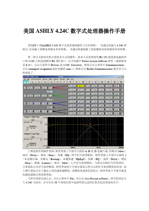
打开电脑中Protea System Software 软件(最新版本是6.13),点击主菜单中Devices 选4.24C Crossover ,接着点击主菜单中Communications ,点击commport assignment 选好电脑的com 口,接着点击Enable Communications 就可以与主上图是软机相连了。
件的操作界面。
软件界面上半部分左面的A 、B 、C 、D 是输入端,有哑音(Mute )、延时击主菜单中File ,再点击Save Present to Protea…即可把设定写入4.(Delay )、增益(Gain )、均衡(EQ )四个信号处理模块。
软件界面上半部分右面的1-8是输出端,有路由(Routing )、高通低通(HpfLpf )、均衡(EQ )、延时(Delay )、增益(Gain )、限幅(Limiter )、哑音(Mute )七个信号处理模块。
当要对音频信号作处理时,只要鼠标点击信号处理模块,软件界面的下半部分就显示所点击的信号处理模块的内容。
如上图中鼠标点击了输出1的高通低通模块,该模块变成黄色的显示,软件界面下半部分就是高通低通频点的设置界面。
当所有设置完成之后,点24C 主机内,并可以在30个预设位置中选择所要记录的位置及更改预设的名字。
第二种方式是通过前面板的按键调整各处理模块的参数。
这种方式主要用于流动系统安装后之后对系统作细微调整。
上图是4.24C 主机前面板。
最左面是RS-232控制端口。

ASHLLY 4.24C24BitDigitalCrossover and System processor 手动操作使用说明目录一介绍 (1)二参数设置 (2)1 功能键和数据调节旋钮 (3)2 预置 (4)2.1 (操作一:如何储存预置) (4)3 输入通路选择 (5)3.1 (操作二:输入通路设置) (5)4 输出通路设置 (5)4.1(操作三:输出通路的选择) (6)4.2 (操作四:参数选择设置的操作) (6)4.3 举例 (7)4.3.1 如何设置EQ的参数 (7)4.3.2 如何设置DELAY (8)4.3.3 如何设置CROSSOVER (9)4.3.4 如何设置LIMITER (10)4.3.5 如何设置起始时间(A__ms) (10)和恢复时间 (R__ms)5 COPY设置的操作方法 (11)6 Mute设置方法 (11)7 Util设置方法 (12)7.1 如何选择full access和full lockout (13)7.2 如何去除密码 (14)7.3 dBu/VU 表选择 (14)7.4 MIDI 通路选择 (15)7.5 工厂设置(如何恢复清除所有预置的名字, (15)恢复工厂设置)一介绍Protea System Ⅱ 4.24C 数字分频器/系统处理器具有与用户界面耦合的4个输入和8个输出,以及作为一个精确的分频器和声音控制系统所要求的全部音频信号处理工具。
使用简单方便,甚至无需人工操控。
可以控制每一输入的增益、延时、和6个滤波器(你可将每个滤波器设置为参数式滤波器或高、低通滤波器)。
可以设置每一输出得分频频率和指定任一输入或任意输入的组合。
此外,还可以通过编程控制4个滤波器(你可将每个滤波器选择为参数式滤波器或高、通滤波器)、调节延时时间和输出增益、反相、控制压缩器/均衡器以保护扬声器系统。
本处理器的外形尺寸为1标准机构空间,输入输出为XLR型连接器。
当然,你也可以通过Ashlly的Protea System Software(Windows 95、98、2000和NT平台)、MIDI或SIA-Smaart 软件进行编程和控制。

D i g i t a l A u d i o P r o d u c t s Digital Crossover System ProcessorOperating Manual目 录1.简介1.1 特点 (1)1.2 用户界面 (1)2.包装 (1)3.电源要求 (1)4.前面板 (1)4.1 功能键和数据轮FUNCTION KEYS & DATA WHEEL (1)4.2 预设PRESETS (2)4.3 输入选择INPUT (2)4.4 输出选择OUTPUT (2)4.5 LED 指示 (2)4.6 功能 (2)4.6a 增益GAIN (2)4.6b 均衡EQ (2)4.6c 延迟DELAY (3)4.6d 分频CROSSOVER (4)4.6e 限幅LIMIT (5)4.7 其他功能 (5)4.7a 唤醒RECALL (5)4.7b 保存SAVE (6)4.7c 复制COPY (6)4.7d 静音MUTE (6)4.7e 便利功能UTILITIES (6)4.7f 工厂设置FACTORY RESET (7)5.连接 (7)6.常见问题 (7)7.尺寸 (8)8.技术规格 (8)9.质量保证 (9)10.用户设置记录 (10)注意:交流电源电压模式选择开关在后面板。
适用从80V到260V交流50~处理器使用了先进DSP数字信号处理感谢您使用数字音频处理器。
Ⅱ1. 简介INTRODUCTION1.1 AUDIO FEATURES 特点技术,输入输出部分使用了24BIT,128倍 48KHz采样率Delta-sigma模/数,模/数转换器。
数字处理部分包括增益调整,极性(相位)转换,参量均衡,数字滤波,时间延迟,压缩限幅和各种分频模式,使用两颗高性能DSP处理器完成所有计算。
所有的输入输出使用平衡带屏蔽的XLR接口。
1.2 USER INTERFACE 用户界面用户界面包括2行20位带背光LCD显示屏和各种功能键可以方便调整各种参数和系统设置。
Congratulations on your purchase of the Ashcroft®digital test gauge with total error band full-scale accuracy and the largest display readout in the industry of .66˝ high. Other industry-leading fea-tures include twelve selectable engineering units, seven languages, and password-protected disable and calibration functions. With the range printed on the keypad, the Ashcroft digital gauge meets the ASME B40.7 digital gauge specification.See a complete listing of product features and specifications on pages 15 & 16.Ashcroft Inc.250 Main StreetStratford, CT 06614-5145Tel: (203) 378-8281Fax: (203) 385-0602e-mail:*****************TABLE OF CONTENTSPage Quick Reference Guide 4-5 Keypad Functions 6 • ON/OFF KEY• BACKLITE KEY• MIN/MAX KEY• ZERO/CLEAR KEY• ENTER KEY• CONFIG KEYConfigurable Functions (CONFIG Mode)• Units (Engineering) 7 • Update Rate 7 • Auto Off 8 • Backlite 8 • Languages 8 • Damping 9 • Contrast 9 • Calibrate (Gauge Calibration) 9-11 • Zero Span 11 • Zero Disable 12 • Disable 13 Available Ranges 14 Specifications 15-16 Installation & Battery Replacement 17 • Mounting• Battery Replacement & InstallationBar graph% of full scale Flashing display when unit pressured below zeroPress to indicate minimum or maximum pressuregauge has measured Press again to return top ressure unitsWhile in max or min mode, press to clear minimum or maximum displayed valuesUNITS (Pressure)ENGLISHPSIINHGINH2O with Temperature (Options: 60°F,4°C, 20°C)FTSWMETRICBARMBARKPAMPAmmHGCMH2OmmH2OKG/CM2UPDATE RATE (Pressure measurement per second)10x*5x2x1xBACKLITE (Off options) ON/OFF* 10 SEC30 SEC1 MIN 5 MINLANGUAGE(s)English*FrenchSpanishGermanItalianPortugueseDutchDAMPING (averages gauge readingNone*AVG 2AVG 4AVG 6AVG 8.66˝ high display, 5 digitQUICK REWhile in unit of measurement mode (eg: psi), press the ZERO CLEAR button to rezero the gauge. This feature functions when displayed pressure is within ±5% of zero valueThis bar graph indicates battery level; the more segments, the closer the battery is to full chargeFlashing display when unit pressured beyond full-scale Press to turn backlite on or offRange on keypad; complies with ASME B40.7Press to turn unit on or offAUTO OFF(Turns unit off after option selected)Never* 2 minutes 5 minutes 15 minutes 30 minutes CALIBRATE Zero and span adjustments, password protectedDISABLE Allows for “lockout” of CONFIG optionsCONTRAST(Customizes display readout)7 availableSelection 4 is Default**Indicates DefaultEFERENCETurns the gauge on and off. When pressing the ON/OFF key while in the off position, gauge start-up display first indicates the software version f ollowed by the model number and gauge pres-sure range. The gauge will then display indicated pressure and be ready for use.Manually turns backlite on and off. (See C ONFIG mode for options).Press this key prior to gauge usage to rezero any initial offset less than ±5% of the rated gauge range. If indicated pressure is greater than 5% of range, the rezero feature becomes inoperable. This prevents accidental tare of a pressurized gauge.To clear minimum and maximum values, press ZERO/CLR button (when min/max values are indicated.This key allows for customization of the gauge. Pressing the CONFIG key allows cycling through the main menu items; UNITS, UPDATE, AUTO OFF, BACKLITE, LANGUAGE, DAMPING,C ONTRAST & CALIBRAT.BACK LITEAllows review of minimum and maximum pres-sure values since unit start-up or last push of the clear button. Press key to:1) I ndicate maximum pressure.2) I ndicate minimum pressure.3) E xit MAX/MIN mode and return to unit of pres-sure measurement mode. To clear minimum and maximum values press ZERO/CLR button. Must be in MAX/MIN mode.Note: MIN/MAX data is lost when unit is turned off.Used in conjunction with CONFIG key, see next page.UNITS: 12 units of measurement are available, both English and metric, by cycling through the UNITS key; psi, ˝Hg, ˝H2O (with three t emperature options, 60°F, 4°C and 20°C), ftSw, Bar, mBar, kPa, mPa, mmHg, cmH2O, mmH2O, kg/cm2.Step 1: P ress the CONFIG key until the wordUNITS appears.Step 2: Press the ENTER key.Step 3: P ress the CONFIG key once to selectE NGLISH or again to select METRIC. Step 4: P ress the ENTER key with selection ofE NGLISH or METRIC.Step 5: P ress CONFIG key to select unit ofm easurement.Step 6: P ress ENTER key to finalize unit ofm easurement.UPDATE: this option allows for changing the rate at which pressure is updated on the display screen. The default rate measures pressure at the maximum rate of 10* updates per second or 100 milli-seconds. Optional rates of measurement are measured in updates per second. The options are 10*, 5, 2 or 1 update of pressure measurement per second.Since customer processes vary, update rates should be selected based on the application.To use the UPDATE option:Step 1: P ress the CONFIG key until the wordUPDATE appears.Step 2: Press the ENTER key.Step 3: P ress the CONFIG key to select the desired update rate.Step 4: Press ENTER key to finalize UPDATE rate. AUTO OFF: this option sets the amount of time be-fore the gauge will turn itself off after no activity. Offerings are Never*, 2, 5, 15, or 30 minutes.To use the AUTO OFF option:Step 1: P ress the CONFIG key until the wordAUTO OFF appears.Step 2: Press the ENTER key.Step 3:P ress the CONFIG key to select the desired AUTO OFF rate.Step 4 P ress the ENTER key to finalize the AUTO OFF rate.BACKLITE: 5 options are available. They include ON/OFF*, 10 seconds, 30 seconds 1 or 5 min-utes. With the ON option pressed, the gauge back-lite will remain lit whenever the gauge is in the ON mode or until the backlite button is pushed again. Options allow the backlite to automatically turn-off after a selected period of time. Note: leaving back-lite button on will decrease battery life.To use the BACKLITE option:Step 1: P ress the CONFIG key until the wordBACKLITE appears.Step 2: Press the ENTER key.Step 3: P ress the CONFIG key to select one of the available time options.Step 4: P ress the ENTER key to finalize yourchoice of BACKLITE options.LANGUAGE: available in seven different languages, this option allows the user to change the default language in the CONFIG mode. The languages in-clude English*, French, Spanish, German, Italian, Portuguese and Dutch.Step 1: P ress the CONFIG key until the wordLANGUAGE appears.Step 2: Press the Enter key.Step 3: P ress the CONFIG key to select one of the available L ANGUAGE options.Step 4: P ress the ENTER key to finalize yourL ANGUAGE optionDAMPING: with six different options, this mode allows for taking process pressure readings and averaging them. This option is particularly useful when there is pulsation in the process. The op-tions are NONE*, AVG 2, 4, 6 or 8.Step 1: P ress the CONFIG key until the wordDAMPING appears.Step 2: Press the ENTER key.Step 3: P ress the CONFIG key to select one of the available D AMPING options.Step 4: P ress the ENTER key to finalize yourDAMPING option.CONTRAST: this mode allows for BACKLITE contrast level. Seven options are available,1, 2, 3, 4*, 5, 6 and 7.Step 1: P ress the CONFIG key until the wordCONTRAST appears.Step 2: Press the ENTER key.Step 3: P ress the CONFIG key to select one of the available C ONTRAST options.Step 4: P ress the ENTER key to finalize yourCONTRAST selection.Note: setting high contrast levels will decrease battery life.CALIBRAT.:Gauge Calibration: Both zero and span ad-justments are available. This gauge has been configured with a default password of ØØØØØ. This factory password does not allow access to calibration. To access the calibration mode, it is necessary to configure a user password. Once the user password is configured, it will become the default password that allows access to gauge calibration.To access the factory default password:Step 1: P ress the CONFIG key until the wordCALIBRAT appears.Step 2: Press the ENTER key.Step 3: The letters/asterisks… PW***** appear. Step 4: P ress the CONFIG key. An Ø appears in the first position.Step 5: Press the ENTER key once.Step 6: P ress the CONFIG key until Ø appears. Ø will appear in the second position.Step 7: Press ENTER.Step 8: U se this format until all the asterisks are replaced with Ø.There now should be a total of five Ø’s on thek eyboard display. The zero in the fifth position should be blinking.Step 9: P ress the ENTER key. You are nowprompted to SET PW (or set password). Step 10: Press the ENTER key.Step 11: D ecide on a five number user password, then follow the procedure above insertinga number in the flashing display until allfive numbers are inserted.Step 12: A SAVE prompt will then appear. If the selected user password is acceptable,press ENTER. If the selected userpassword is not acceptable press ZEROCLEAR to refigure the user password. After the password is configured, the default factory password will be replaced with the user password. Once configured, the factory password is no longer accessible.If an incorrect password is entered, the system will display WRONG. Press the CONFIG key to reenter the correct password.Step 13: Press ENTER again to begin calibration. Note: Calibration feature allows recalibration of zero and span.Zero Calibration:Step 14:P ress the CONFIG key once and the word CALIBRA appears. Press ENTER. (Thismode allows for 0 and full- scale adjust-ment of span.) The gauge will now display0.00. Ensure the gauge is not pressurized,1then press ENTER to zero the gauge. Zerocalibration is now complete.Full Scale CalibrationStep 15:T he gauge will now display full-scalerange (e.g. 100.00 psi). Pressurize thegauge to 100% of the range (which isequal to the displayed value) utilizing apressure standard with accuracy fourtimes greater than the unit being cali-brated.2Press ENTER. Full-scale calibra-tion is now complete.Notes:1. I f the digital gauge under test is not pressurized while in span adjustment of full-scale range,an ERROR message will be displayed when the ENTER button is pressed. If this occurs, press the ZERO CLEAR button on the keypad to return to the previous screen.2. A SME B40.7-1998, section 6.1.1.1 recommends the working standard for the gauge being tested is 4X better than the digital gauge under test. This means the pressure standard measuring the full-scale pressure being applied to the gauge should have an accuracy four times greater than the unit being spanned.Zero SP (span):This feature allows setting the % of span in which the zero button will operate. Span is limited to pre-vent accidental tare of process pressures. Options are 5%, 10% or DISAB (5% is the factory default and means the unit can be r ezeroed between ±5% of span). If DISAB is selected, the zero button is deactivated and no display change will occur when the zero button is pushed.Step 1:P ress the CONFIG key until the word ZERO SP appears.Step 2: Press ENTER.Step 3:E nter user five digit password (PW). This is the same password established to accessthe CONFIG mode in the menu.Step 4:P ress the CONFIG key to select thedesired option.Step 5:P ress ENTER to finalize the selection. Notes:Selecting the DISAB feature does not disable the CLEAR button on the keypad for the MAX/MIN fea-ture. If the DISAB feature is selected, pressing the ZERO button on the keypad will cause the display to read DISAB for two seconds. The gauge will then revert back to the unit of measure of the gauge. The DISAB feature disables the zero feature of the gauge. Zero Disable Feature:This feature allows disabling the Zero/Clear button on the keypad. It also allows for a zero tolerance of either 5% (default) or 10% of the gauge range. Step 1:P ress the CONFIG key until the word ZERO SP appears.Step 2:Press ENTER.Step 3:A prompt appears to enter PW (enterpassword). The ZERO SP password isthe same password as discussed on page10 and the heading CALIBRAT:, GaugeCalibration. Follow the instructions onpage 10 to enter a password.Step 4:P ress the CONFIG key to select the zero tolerance, either 5% or 10% of range, orpress the CONFIG key again and the wordDISAB appears. Press ENTER to select thenew default setting.If the user password is lost or stolen, contact Ashcroft Inc., customer service at (203) 378-8281 for a new factory password that will allow the user to establish a new user password.DISABLE: allows “lockout” of individual CONFIG options. The default is ENABLE for all options in the CONFIG mode.Step 1: P ress the CONFIG key until the wordDISABLE appears.Step 2: Press the ENTER key.Step 3: I nsert the user password following the procedure as described in steps 3 through13 above.Note: This is the same user password as in the CALIBRAT mode.Step 4: P ress the ENTER key.Step 5: T he first option in the CONFIG menu will now be displayed (UNITS).Step 6: T o DISABLE the UNITS option pressthe ENTER key until the word DISABLEappears.Step 7: P ress the CONFIG key. The UNITS option is now DISABLED.Step 8: P roceed through the balance of theCONFIG menu options by pressing theCONFIG key. Follow steps 6-8.DIGITAL TEST GAUGE RANGESWARNING AND ERROR MESSAGESGauge Installation:Pipe Mount – The Ashcroft digital test gauge comes standard with a 1⁄4 NPT connection. Good piping practices recommend using teflon tape or a pipe sealant on the gauge threads. Utilize a 7⁄16˝ wrench on the wrench flat of the gauge to tighten the gauge to the process.NEVER TIGHTEN GAUGE THREADS BY HOLDING THE BODY OF THE GAUGE. DOING SO MAY DAMAGE THE GAUGE AND MAKE THE GAUGE INOPERABLE.Panel Mount – The lower connected Ashcroft digital test gauge is available with an optional flange for panel mounting. Please refer to illustration and dimensions below.m Pipe to which gauge is attached must be properly grounded.Battery Installation and Replacement:The gauge comes standard with three AAA alkaline batteries installed. For battery replacement use only one of the three types listed below:• Energizer AAA alkaline, E92 LR03 AM4 1.5V• Energizer AAA alkaline, EN92 LR03 AM4 1.5V• Duracell AAA alkaline, MN2400 LR03 1.5VDo not mix ages or brands of batteries. Do not replace batteries in hazardous areas.Batteries have a life of approximately 1000 hours. Battery life is dependent on gauge usage, backlite settings and power off settings. When the display flashes LOW BAT, batteries should be replaced.To replace the batteries:1) R emove the single screw on the back of the gauge case.2) H old the keypad in the palm of hand.3) C arefully remove the three batteries from the holder and replace the batteries. Use only AAA alkaline non-rechargeable batteries.Ashcroft Inc.250 Main StreetStratford, CT 06614-5145Tel: (203) 378-8281Fax: (203) 385-0602e-mail:*****************©Ashcroft Inc. 2022 I&M008-10080_RevG_02-03-22。
varian-lc-galaxie中文操作手册Galaxie Workstation高效液相層析儀操作講義1美商亞洲瓦里安科技股份有限公司台灣分公司3 第一章執行儀器之開關機3 1.1 6 開機步驟 1.2關機步驟9 第二章分析方法之建立 View/Edit Methods18 第三章進行樣品之分析183.1 22 執行單一注射 Single Injection 3.2執行多重注射 Multi-Injections27 第四章資料再處理 Data Handling274.1 32 定性方法說明 4.2定量方法說明41 第五章報表製作 Report2第一章執行開關機步驟 (HPLC系列 210/325/410)的設定 1.1開機步驟Step 1 於開機前請先確認下列幾項狀態:1. 確認載流液體溶液是否正確。
2. 確認載流液體溶液是否充足。
3. 確認載流液體溶液是否已經做了去除氣泡之動作。
4. 確認管柱之方向是否正確。
於機台與電腦連線前請先確認下列幾項狀態:甲、請先單獨將幫浦電源打開。
乙、並將Purge valve打開,讓幫浦做Prime之動作使其管路中無氣泡。
丙、當管路中無氣泡時,記得要將Purge valve關閉。
當以上所需確認之動作步驟均已確實執行後,請將電腦開啟,直至出現以下畫面,並點選桌面上之”Galaxie”捷徑。
3請點選此圖示Step 2 (i) User identification處Key in 登入名稱。
(ii) 選擇所屬之Group、Project。
(iii) Key in password。
(iv) 輸入完成後請點選右方”OK”鍵。
4Step 3 1. 點選ok後會出現以下畫面。
請點選”System”。
Step 4 1. 點選小方格(軟體與機台連線)5Step 5 此時可由下方Status overview(按下左方overview,選擇”General”)可觀察目前機台各項參數之狀態。
Active load ASC-50WGeneralThe ASC-50W compact electronic DC load, is the first generation of small desktop loads with a power rating of 50 Wmax. It offers voltage, current and power ratings for a multitude of applications for daily use in laboratories, schools or workshops. This model supports the for now regulation modes constant current (CC) and constant power (CP). The core of the control circuit is a fast-high performance analog amplifier/multiplier supported by microcontroller which provides interesting features, such as a load step generator push buttons and display control. The display, together with push buttons and rotary potentiometers, enables the user an intuitive kind of manual operation and better overview. Programmable Electronic DC LoadInput power rating: 0...50 WmaxInput voltage: 0...50 VmaxInput current: 0...10 AmaxLoad step generator (100Hz fixedfrequency)Adjustable trip point (UVLO)Operation modes: CC, CPLCD displayTemperature dependent Fan controlFeaturesFront side view10413276598Back side view121. Display2. ON/OFF Push button3. Pulse Push Button4. Preset Push Button5. I/P Push Button6. Coarse Potentiometer7. Fine Potentiometer8. UVLO Potentiometer9. PULSE Potentiometer 10. Preset LED (green)Pulse LED (yellow) ON/OFF LED (red)1. 4 mm Banana plugsRed for positive and Blue for return line 2. Plug for external 12VDC SupplyASC-50W device is standard delivered with external AC/DC wall plug adapter.All various AC input plugs are included. Manufacturer: XP Power Type: VER12US120-JAHandling (HMI)Manual operation is done with a LCD display, four rotary potentiometers and four pushbuttons. The display shows all relevant set values and actual values at a glance. The display is operated only on English.ON/OFF ButtonPress the button to switch ON or OFF the load current or power. If Under Voltage Lock Out (UVLO) set value higher then supply voltage, pressing the ON/OFF button will bring device in to ready state only. If in ON or ready state, the red LED will light ONI/P ButtonOnes device powered, by default will go in to Constant Current (CC) mode.Press the button to change from (CC) in to Constant Power (CP) mode.PULSE ButtonThis model includes a load step generator which can generate one typical function needed for power supply testing. Frequency generated is 100Hz with 50% duty cycle. The level of load step is defined by potentiometer “Pulse”. This can be applied to current or power.Press the button to enable or disable this function. If Under Voltage Lock Out (UVLO) set value higher then supply voltage, pressing the ON/OFF button will bring device in to ready state only.Yellow LED blinking if generator enabled.Under Voltage Lock OutVery nice feature we included, is the possibility to set the trip point. This can be done by operating potentiometer UVLO. The level can be seen on display by pressing button “PRESET”. The load will stay in OFF mode till the input voltage hits the threshold level. Ones this happen, the load will be switched ON and regulate to set point. At the same time a hysteresis will be applied to this UVLO value to avoid oscillations. This is in range of 10% of the input voltage value.Preset ButtonPush the button to see UVLO adjustment and inactive load function:if device operates in CC mode you will see CP mode setup and vise versa.Pushing the PRESET button the green LED will light onCoarce and Fine PotentiometersCoarce is multiple turns potentiometer (10x), Fine is a single turn potentiometer. Operating it, it is possible to adjust current or power set point. Fine potentiometer alows you to have fine adjustments (in 10% range). Be aware, to get the maximum possible set point, both potentiometers must reach the maximum position.Product specification12VDCMax 2.5W<2%<2%Temperature controlled fan0°C…40°C-20°C…70°C70x122x190950gEN 61326-1Layout dimensionsCustomer supportFor any details contact authorized local distributor or Ascalab directly: Email:****************Phone: +386 1 2350102Warranty valid 1 year after purchase order.We shall reply to you at earliest convenience.。
D i g i t a l A u d i o P r o d u c t s3.24CLDigital CrossoverSystem ProcessorOperating ManualASHLY AUDIO INC.847 Holt Road Webster, NY 14580-9103 Phone: (585) 872-0010 Toll-Free: (800) 828-6308 Fax: (585) 872-0739 目 录1.简介1.1 特点 (1)1.2 用户界面 (1)2.包装 (1)3.电源要求 (1)4.前面板 (1)4.1 功能键和数据轮FUNCTION KEYS & DATA WHEEL (1)4.2 预设PRESETS (2)4.3 输入选择INPUT (2)4.4 输出选择OUTPUT (2)4.5 LED 指示 (2)4.6 功能 (2)4.6a 增益GAIN (2)4.6b 均衡EQ (2)4.6c 延迟DELAY (3)4.6d 分频CROSSOVER (4)4.6e 限幅LIMIT (5)4.7 其他功能 (5)4.7a 唤醒RECALL (5)4.7b 保存SAVE (6)4.7c 复制COPY (6)4.7d 静音MUTE (6)4.7e 便利功能UTILITIES (6)4.7f 工厂设置FACTORY RESET (7)5.连接 (7)6.常见问题 (7)7.尺寸 (8)8.技术规格 (8)9.质量保证 (9)10.用户设置记录 (10)1. 简介INTRODUCTION感谢您使用ASHLY Protea 3.24CL 数字音频处理器。
如ASHLY的其他产品一样, Protea 系列处理器保持了ASHLY在质量和价值上的传统优势,和市场的领先地位。
新的3.24CL音频信号处理器提供三进六出信号接口,更在前面板提供丰富的功能按钮可以更精确,更直观地调控各项参数,避免了过多隐藏菜单引起的不便。
1.1 AUDIO FEATURES 特点Protea 3.24CL 使用了先进DSP数字信号处理技术,输入输出部分使用了24BIT,128倍 48KHz采样率Delta-sigma模/数,模/数转换器。
数字处理部分包括增益调整,极性(相位)转换,参量均衡,数字滤波,时间延迟,压缩限幅和各种分频模式,使用两颗高性能DSP处理器完成所有计算。
所有的输入输出使用平衡带屏蔽的XLR接口。
1.2 USER INTERFACE 用户界面用户界面包括2行20位带背光LCD显示屏和各种功能键可以方便调整各种参数和系统设置。
显示屏可以显示预设号码,然后选择输入输出通道和控制参数。
每个输入输出端口都提供一排五段LED灯用来显示增益水平和静音状态。
2. UNPACKING 包装作为质量控制的一部分,所有ASHLY产品在出厂前都经过仔细的检验,以确保品质和外观完美无瑕。
打开包装后,请仔细检查外观是否有物理损坏。
包装箱和包装材料是专为保护机器在运输过程中不受损害而设计,拆机后请保留机器的外包装。
另外如果发现机器交到您手中时已经破损,请马上联系当地销售商,以便尽快填写赔偿申请表格。
向运送者申请赔偿的同时必须出示原厂包装,所以请务必保存原厂包装直到解决赔偿的问题。
3. AC POWER REQUIREMENTS 电源要求注意:交流电源电压模式选择开关在后面板。
Protea 3.24CL适用从80V到260V交流50~60Hz的各种电源模式。
在后面板还提供有标准IEC-320带地线交流输入插头。
(千万不要去掉3.24CL上的地线连接头)保险丝熔断后,一定要联系专业人员使用相同规格保险丝替换。
4. FRONT PANEL CONTROL FEATURES 前面板功能4.1 Function Keys and Data Wheel 功能键和数据轮LED显示屏右边有两个没有标识的功能键和数据轮。
所有参数都是通过它们进行调节。
显示屏的每一行所显示的内容分别对应上下两个功能键,可以分别使用这两个功能键选择屏幕上的不同功能。
被选择的功能在屏幕上会以背光显示,并有下划线在在字母下方闪烁,这时就可以用数据轮来调节参数。
ESC退出键用来退出正在使用的功能到最上一层菜单(显示为预设名称和号码)。
4.2 Presets预设3.24CL共有30个可编辑预设,每个预设都包括三进六出通道的独立参数调节。
其中预置了十种工厂预设,应用于系统的日常使用。
这些预设也可以按用户的要求编辑,重命名和存储。
注意:除30个预设以外,还提供一个实时监控的预设程序(WORKING PRESET)可以不断刷新并记录预设的变更,用来防止以外断电造成的是数据丢失。
当3.24CL开机时,最近使用的(关机前)预设会自动加载,并在显示屏上显示。
任何在存储前(SAVE)对预设的更改将保存在WORKING PRESET中,直到更改被存储,或载入另外一种预设。
如果对正在使用的预设的数据更改而没有进行保存,显示屏将会自动在该预设号码前加上“modified”的文本提示。
4.3 Input Select 输入选择3.24CL共有三路独立输入,可以分别调节增益,均衡,延时和静音,并在输出端之前提供自由的路由功能。
(可以被路由至任意的一个或多个输出端口)4.4 Output Select 输出选择3.24CL共有六路独立输出,每个输出端口都可从任意的一个或多个输入端获得信号,或者全部设为旁路(没有输入)。
每个输出端都提供独立的增益,相位,均衡,延时分频和限幅调节功能。
4.5 LED Indicators每个输入和输出都带有一个五段式LED指示灯显示信号电平,范围从-20到削波限幅。
-20LED灯有两种颜色,该指示灯显示为红色时代表该路接口被设置为静音。
工厂预设的零值代表0dBu(0.775Vrms),也可以通过功能菜单切换到VU水平的零值(0=+4dBu,或者是1.228Vrms)。
4.6 Audio Functions4.6a Gain输入和输出水平分别调节,步进为0.1dB范围从-40dB 到+12dB。
输出增益菜单下可以为指定输出端口选择不同相位(+,—)和输入信号(A,B,C,A+B,A+B+C和旁路)。
请注意,两路相关的信号被合并为一路输出时,最多会产生6dB的增益。
4.6b EQ 均衡均衡部分提供参量滤波和两种斜坡SHELVING滤波器模式。
每个输入通道有六个滤波器可以选择;而每个输出通道有四个滤波器。
每个滤波器都可以在参量均衡(PEQ),两种低频滤波(1st,2nd LOW SHELF),两种高频滤波(1st,2nd HIGH SHELF)五种模式之间选择。
斜坡SHELVING EQ 滤波器:第一种1st滤波器斜率比较平缓(6dB/OCTAVE),而第二种2nd使用12dB/OCTAVE斜率滤波器提供更显著的的提升和衰减。
所有滤波器的提升和衰减范围都是±15dB,低频滤波器的频率范围从19.7Hz到2KHz,高频滤波器的频率范围从3.886KHz到21.9KHz。
斜坡滤波器在语音控制方面非常有效,可以提升和切除信号的高频和低频部分,因为这些部分对音频信号干扰很大。
但是在反馈抑制方面参量均衡滤波器会更适合。
PEQ参量均衡:参量均衡可以调节增益,中心频点,带宽。
可以把参量均衡看成是一种特殊的,中心频点和带宽可调的图示均衡。
带宽越窄,受影响的信号越少;带宽越大,影响的范围越大。
参量均衡最适合用于除去麦克风的声反馈或房间的回音。
Protea 3.24CL参量均衡的增益范围从+15dB到-30dB。
因为参量均衡一般应用在非常窄的频带切除反馈频率,所以衰减调节的范围更大。
每个参量均衡都有一个中心频率。
工厂默认的中心频率是1KHz,但是每个滤波器的中心频率都可以在19.7Hz到21.9 KHz以1/24的步进调节。
寻找反馈点时,可以先选取一个窄带参量滤波器,然后在反馈发生的频率周围仔细调节滤波器的中心频率。
只需很少的提升,就可以发现反馈发生的频点。
一旦发现该频点,马上切掉。
这样我们就可以用尽可能窄的带宽损失消除声反馈。
带宽可以在1/64 OCTAVE和4 OCTAVE之间调节,带宽越小,对信号带来的损失越少。
发现反馈点很容易,但要找到消除反馈最佳的增益,频率和带宽的组合需要一定的经验。
所有的三个输入六个输出通道都有一个象征性的均衡功能的开关。
只需把需要关闭均衡功能的通道的均衡增益调到0.0dB,那个通道的信号就不会受均衡影响。
4.6c Delay 延时在大型厅堂或户外扩声使用时,常需要在不同地点摆放很多音箱以实现更平均的声压覆盖。
但考虑到音速的原因(344米/秒),不同音箱发出的声音到达观众的时间并不同步,影响了听音效果。
解决的方法就是为远离舞台的音箱加入延迟,这样就可以使远离舞台的音箱和舞台的主音箱发出的同步声音。
Pretea 3.24为每个通道提供了最大682毫秒的延迟,可以达到235米距离的延迟效果。
输出通道也需要延迟功能,但程度要不输入通道上的延迟小很多。
这是因为输出延迟主要是应用在一个音箱或音箱簇,他们之间的距离非常接近。
比如说,典型的三分频(如下图)高频,中频和低频扬声器上下排列在一起。
但是不同扬声器的发音点的位置并不像它们安装在面板上的位置那样在垂直平面上保持一直。
这样,相同的信号(在分频时)经过不同的扬声器在到达箱体面板处的时间不一致,因而产生干涉甚至抵消。
解决的办法就是为不同的扬声器加上延时。
使用音膜离音箱背板最近的单元作为参考,计算他们在水平方向上的相互距离。
参考单元不加延迟,而音膜最接近音箱面板的单元加上最多延迟。
注意:虽然在3.24CL上延迟的计算是以时间为单位,用户仍然可以在显示屏上看见对应的距离。
(以英尺和米来表示)4.6d Crossover (Xover) 分频在输出通道可以选择分频功能。
每个通道的分频功能包括:高通滤波HPF和低通滤波LPF,还有相应的频率和滤波器的类型。
可以把它看作带通滤波器,让用户在输出之前选择需要的频率范围。
高通决定低频的范围,低通决定高频的范围。
高通的范围从19.7Hz到21.9 KHz,选择最低的频率19.7Hz代表取消高通滤波。
低通滤波器也提供一样的频率范围,选择最高的频率以取消低通功能。
共有11种滤波器类型可以在分频功能内选择。
滤波器类型前面的字母用来表示滤波器的斜率。
12dB,18dB,24dB和48dB/OCTAVE。
斜率越高,带通之外频率衰减越快。
并没有一个所谓最好的斜率,可以根据应用环境不同按自己的喜好决定滤波器的斜率。
ASHLY 的出厂预设值是24dB Linkwitz-Riley,用户可以自己调整。
除了频率和斜率,分频滤波器可以选择Butterworth, Bessel或Linkwitz-Riley三种响应曲线。