基于FPGA的温度传感器DS B 读写代码
- 格式:pdf
- 大小:61.55 KB
- 文档页数:18
基于FPGA温度传感器DS18B20的Verilog设计赖青松(江西师范大学南昌电子信息工程)摘要: 本文利用数字温度传感器DS18B20 的数据接口和特点,阐述了一种基于现场可编程门阵列( FPGA)控制DS18B20的方法。
使用FPGA 作为控制器,严格控制DS18B20 的时序,在单总线上实现读写功能,完成测量数字温度的功能。
将测量的二进制数转换为BCD 码,并通过数码管显示。
系统设计使用Verilog 语言。
由于DS18B20 是采用一根I/ O 总线读写数据,因此DS18B20 对读写数据位有严格的时序要求。
DS18B20 遵循相应的通信协议从而保证数据传输的正确性和完整性。
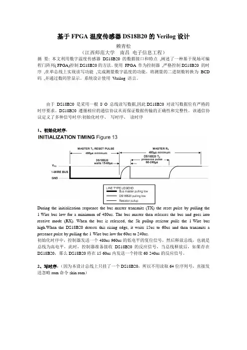
该通信协议定义了多种信号时序:初始化时序、写时序、读时序1、初始化时序:During the initialization sequence the bus master transmits (TX) the reset pulse by pulling the 1-Wire bus low for a minimum of 480us. The bus master then releases the bus and goes into receive mode (RX). When the bus is released, the 5k pullup resistor pulls the 1-Wire bus high.When the DS18B20 detects this rising edge, it waits 15us to 60us and then transmits a presence pulse by pulling the 1-Wire bus low for 60us to 240us.初始化时序中,控制器发送一个480us-960us的低电平的复位信号,然后释放总线,也就是总线为高电平,此时,控制器准备接收DS18B20的反应信号,当总线释放后,如果存在DS18B20,那么DS18B20将在15-60us内发送一个持续60-240us的反应信号。
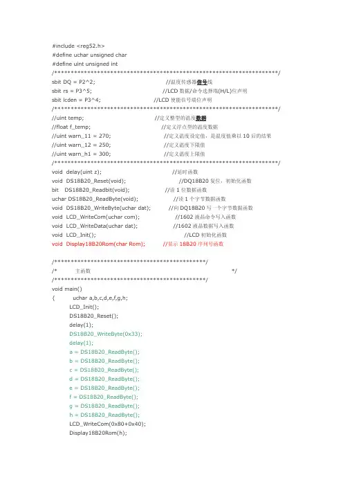
#include <reg52.h>#define uchar unsigned char#define uint unsigned int/********************************************************************/ sbit DQ = P2^2; //温度传感器信号线sbit rs = P3^5; //LCD数据/命令选择端(H/L)位声明sbit lcden = P3^4; //LCD使能信号端位声明/********************************************************************/ //uint temp; //定义整型的温度数据//float f_temp; //定义浮点型的温度数据//uint warn_11 = 270; //定义温度设定值,是温度值乘以10后的结果//uint warn_12 = 250; //定义温度下限值//uint warn_h1 = 300; //定义温度上限值/********************************************************************/ void delay(uint z); //延时函数void DS18B20_Reset(void); //DQ18B20复位,初始化函数bit DS18B20_Readbit(void); //读1位数据函数uchar DS18B20_ReadByte(void); //读1个字节数据函数void DS18B20_WriteByte(uchar dat); //向DQ18B20写一个字节数据函数void LCD_WriteCom(uchar com); //1602液晶命令写入函数void LCD_WriteData(uchar dat); //1602液晶数据写入函数void LCD_Init(); //LCD初始化函数void Display18B20Rom(char Rom); //显示18B20序列号函数/**********************************************//* 主函数 *//**********************************************/void main(){ uchar a,b,c,d,e,f,g,h;LCD_Init();DS18B20_Reset();delay(1);DS18B20_WriteByte(0x33);delay(1);a = DS18B20_ReadByte();b = DS18B20_ReadByte();c = DS18B20_ReadByte();d = DS18B20_ReadByte();e = DS18B20_ReadByte();f = DS18B20_ReadByte();g = DS18B20_ReadByte();h = DS18B20_ReadByte();LCD_WriteCom(0x80+0x40);Display18B20Rom(h);Display18B20Rom(g);Display18B20Rom(f);Display18B20Rom(e);Display18B20Rom(d);Display18B20Rom(c);Display18B20Rom(b);Display18B20Rom(a);while(1);}/***************************************************//* 延时函数:void delay() *//* 功能:延时函数 *//***************************************************/void delay(uint z)//延时函数{uint x,y;for( x = z; x > 0; x-- )for( y = 110; y > 0; y-- );}/***************************************************//* DS18B20函数:void DS18B20_Reset() *//* 功能:复位18B20 */ /***************************************************/void DS18B20_Reset(void)//DQ18B20复位,初始化函数{uint i;DQ = 0;i = 103;while( i > 0 ) i--;DQ = 1;i = 4;while( i > 0 ) i--;}/***************************************************//* DS18B20函数:void DS18B20_Readbit() *//* 功能:读1个字节数据函数 *//***************************************************/bit DS18B20_Readbit(void) //读1位数据函数{uint i;bit dat;DQ = 0;i++; //i++起延时作用DQ = 1;i++;i++;dat = DQ;i = 8;while( i > 0 )i--;return( dat );}/***************************************************//* DS18B20函数:void DS18B20_ReadByte() *//* 功能:读1个字节数据函数 */ /***************************************************/uchar DS18B20_ReadByte(void) //读1个字节数据函数{uchar i,j,dat;dat = 0;for( i = 1; i <= 8; i++ ){j = DS18B20_Readbit();dat = ( j << 7 ) | ( dat >> 1 );}return(dat);}/***************************************************//* DS18B20函数:void DS18B20_WriteByte() *//* 功能:向DQ18B20写一个字节数据函数 *//***************************************************/void DS18B20_WriteByte(uchar dat) //向DQ18B20写一个字节数据函数{uint i;uchar j;bit testb;for( j=1; j<=8; j++){testb = dat&0x01;dat= dat>>1;if(testb) //写1{DQ = 0;i++;i++;DQ = 1;i = 8;while(i>0)i--;}else{DQ = 0; //写0i = 8;while(i>0)i--;DQ = 1;i++;i++;}}}/***********************************************//* LCD函数:void LCD_WriteCom() *//* 功能:向LCD写入命令 *//***********************************************/void LCD_WriteCom(uchar com){rs = 0;P0 = com;delay(5);lcden = 0;delay(5);lcden = 1;delay(5);lcden = 0;}/***********************************************//* LCD函数:void LCD_WriteData(uchar dat) *//* 功能:向LCD写入数据 *//***********************************************/void LCD_WriteData(uchar dat){rs = 1; //选择LCD为写入数据状态lcden = 0;P0 = dat; //将待写入数据放到总线上delay(5);lcden = 1; //给LCD使能端一个脉冲delay(5); //信号将之前放到总线上lcden = 0; //的数据写入LCDdelay(5);}/***********************************************//* LCD函数:void LCD_Init() */ /* 功能:初始化LCD,设定LCD的初始状态 *//***********************************************/void LCD_Init(){LCD_WriteCom(0x38); //LCD显示模式设定delay(15);LCD_WriteCom(0x08); //关闭LCD显示delay(3);LCD_WriteCom(0x01); //LCD显示清屏delay(3);LCD_WriteCom(0x06); //设定光标地址指针为自动加1delay(3);LCD_WriteCom(0x0c); //打开LCD显示,但不显示光标}/**********************************************//* */ /* 显示18B20序列号 *//* *//**********************************************/void Display18B20Rom(char Rom){uchar h,l;l = Rom & 0x0f; //取低4位h = Rom & 0xf0; //取高4位h >>= 4;if( ( h >= 0x00 )&&( h <= 0x09 ) )LCD_WriteData(h+0x30); //取ASCII码elseLCD_WriteData(h+0x37); //取ASCII码if( ( l >= 0x00 )&&( l <= 0x09 ) )LCD_WriteData(l+0x30); //取ASCII码elseLCD_WriteData(l+0x37); //取ASCII码}。

基于FPGA的DS18B20控制程序设计及其Verilog实现一,总体介绍DS18B20是一个1-wire总线,12bit的数字温度传感器,其详细的参数这里不做具体的介绍,只讨论其基于Verilog的控制程序的设计。
实际上,对DS18B20的控制,主要是实现1-wire总线的初始化,读,写等操作,然后再根据DS18B20的控制要求,实现对其控制的verilog逻辑。
在1-Wire总线上,有一个master,可以有1个或者多个slave。
而对于FPGA+DS18B20的温度测试设计来讲,需要在FPGA上实现一个1-Wire总线的master。
DS18B20作为1-wire 总线的slave设备存在,可以有一个或者多个,不过为了简化程序,例程里假定只存在一个DS18B2020。
1-Wire总线的操作形式上相对简单,但操作本身相对却又比较复杂。
用Verilog做控制程序设计时,可以采用多层次嵌套的状态机来实现。
二,FPGA + DS18B20的硬件设计硬件的设计非常简单,只需要将DS18B20的DQ与FPGA的一个IO连接,并加4.7K左右的上拉电阻就可以了。
VDD和VPU可以为3.0~5.0V。
这里我们参照FPGA本身的IO电压,选择3.3V。
另外要注意的一点是,由于DQ的数据是双向的,所以FPGA的该IO要设定为inout类型。
三,1-Wire总线的基本操作及Verilog实现。
根据1-Wire总线的特点,可以把1-Wire总线的操作归结为初始化,单bit读操作,单bit写操作等最基础的几种。
下面分别是几种基本操作的介绍和verilog实现。
由于DS18B20的时序操作的最小单位基本上是1us,所以在该设计中,全部采用1MHz的时钟。
1. 初始化初始化实际上就是1-wire总线上的Reset操作。
由master发出一定长度的初始化信号。
Slave 看到该初始化信号后,在一定时间内发出规定长度的响应信号,然后初始化操作就结束了。
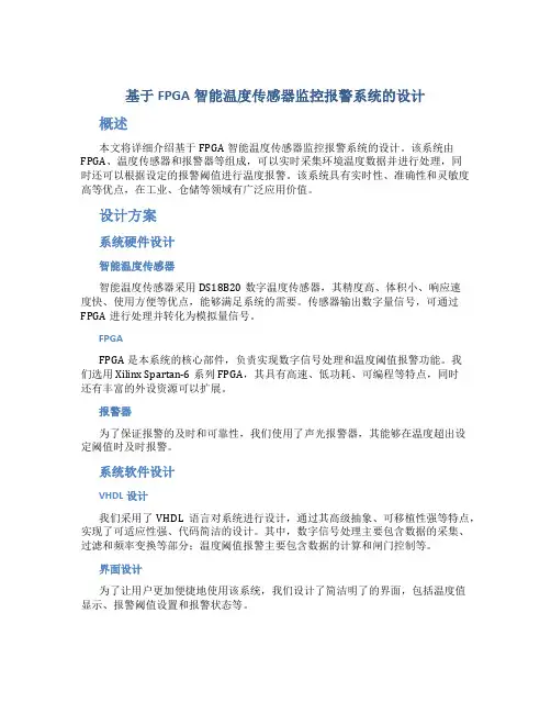
基于FPGA智能温度传感器监控报警系统的设计概述本文将详细介绍基于FPGA智能温度传感器监控报警系统的设计。
该系统由FPGA、温度传感器和报警器等组成,可以实时采集环境温度数据并进行处理,同时还可以根据设定的报警阈值进行温度报警。
该系统具有实时性、准确性和灵敏度高等优点,在工业、仓储等领域有广泛应用价值。
设计方案系统硬件设计智能温度传感器智能温度传感器采用DS18B20数字温度传感器,其精度高、体积小、响应速度快、使用方便等优点,能够满足系统的需要。
传感器输出数字量信号,可通过FPGA进行处理并转化为模拟量信号。
FPGAFPGA是本系统的核心部件,负责实现数字信号处理和温度阈值报警功能。
我们选用Xilinx Spartan-6系列FPGA,其具有高速、低功耗、可编程等特点,同时还有丰富的外设资源可以扩展。
报警器为了保证报警的及时和可靠性,我们使用了声光报警器,其能够在温度超出设定阈值时及时报警。
系统软件设计VHDL设计我们采用了VHDL语言对系统进行设计,通过其高级抽象、可移植性强等特点,实现了可适应性强、代码简洁的设计。
其中,数字信号处理主要包含数据的采集、过滤和频率变换等部分;温度阈值报警主要包含数据的计算和闸门控制等。
界面设计为了让用户更加便捷地使用该系统,我们设计了简洁明了的界面,包括温度值显示、报警阈值设置和报警状态等。
系统实现硬件实现按照上述设计方案,我们完成了硬件电路的设计,其中智能温度传感器采用了标准接口,与FPGA连接顺畅稳定。
报警器也能有良好的响应效果。
软件实现通过VHDL语言,我们完成了数字信号处理和温度报警部分的代码编写,在模拟器中进行了仿真和调试,并进行了综合和布局。
最终在FPGA平台上进行了验证,并与界面进行了充分交互。
结果分析经过系统实现,我们完成了一个基于FPGA智能温度传感器监控报警系统的设计。
在实际测试中,该系统具有所需的准确性、灵敏度和实时性等特点,能够实时采集环境温度并进行温度阈值报警。

FPGA课程设计论文学生姓名周悦学号20091321018院系电子与信息工程学院专业电子科学与技术指导教师李敏二O一二年5月28 日基于FPGA的温度传感器系统设计1引言温度是一种最基本的环境参数,人们的生活与环境的温度息息相关,在工业生产过程中需要实时测量温度,在农业生产中也离不开温度的测量,因此研究温度的测量方法和装置具有重要的意义。
测量温度的关键是温度传感器,温度传感器的发展经历了三个发展阶段:传统的分立式温度传感器;模拟集成温度传感器;智能集成温度传感器。
目前,国际上新型温度传感器正从模拟式向数字式,从集成化向智能化、网络化的方向飞速发展。
本文将介绍采用智能集成温度传感器DS18B20,并以FPGA为控制器的温度测量装置的硬件组成和软件设计,用液晶来实现温度显示。
2电路分析系统框图如下:第一部分:DS18B20温度传感器美国 Dallas 半导体公司的数字化温度传感器 DS1820 是世界上第一片支持 "一线总线"接口的温度传感器,在其内部使用了在板(ON-B0ARD)专利技术。
全部传感元件及转换电路集成在形如一只三极管的集成电路内。
一线总线独特而且经济的特点,使用户可轻松地组建传感器网络,为测量系统的构建引入全新概念。
现在,新一代的 DS18B20 体积更小、更经济、更灵活。
使你可以充分发挥“一线总线”的优点。
DS18B20 的主要特性:(1)适应电压范围更宽,电压范围:3.0~5.5V,在寄生电源方式下可由数据线供电(2)独特的单线接口方式,DS18B20 在与微处理器连接时仅需要一条口线即可实现微处理器与DS18B20 的双向通讯(3)DS18B20 支持多点组网功能,多个DS18B20 可以并联在唯一的三线上,实现组网多点测(4)DS18B20 在使用中不需要任何外围元件,全部传感元件及转换电路集成在形如一只三极管的集成电路内(5)温范围-55℃~+125℃,在-10~+85℃时精度为±0.5℃(6)可编程的分辨率为 9~12位,对应的可分辨温度分别为 0.5℃、0.25℃、0.125℃和 0.0625℃,可实现高精度测温(7)在 9 位分辨率时最多在93.75ms 内把温度转换为数字,12 位分辨率时最多在 750ms 内把温度值转换为数字,速度更快(8)测量结果直接输出数字温度信号,以"一线总线"串行传送给 CPU,同时可传送 CRC 校验码,具有极强的抗干扰纠错能力(9)负压特性:电源极性接反时,芯片不会因发热而烧毁,但不能正常工作。

基于FPGA的数字温度传感器控制方法摘要:本文作者结合实际工作经验,首先介绍了数字温度传感器DS18B20的数据接口和特点,并阐述了一种基于现场可编程门阵列(FPGA)控制DS18B20的方法,最后对基于FPGA的数字温度传感器控制方法进行了深入的研究,具有重要的参考意义。
关键词:现场可编程门阵列;数字温度传感器;硬件描述语言0.引言随着市场经济和现代工业、农业、国防等领域的高速发展,测试控制系统技术已经成为现代企业生产能力、市场竞争力和高科技中的一项不可缺少的核心技术。
测试控制装备也己经成为各个工业控制、国防安全、民用家居的一个重要的组成部分。
在科学研究和工程实践的过程中,测试和控制是整个应用系统的两个最主要的任务,也是体现整个系统处理实际工程问题、撤禾4?开参考材料的重要途径。
测试控制系统在工程控制和工业生产中起着指导者和检验者的作用,它从现场获取各种实际参数,运用科学规律和系统工程分析方法,综合有效地运用各种先进实用的技术,通过控制手段和设备,使各个测试和控制环节得到良好运行与优化。
目前,测试控制技术广泛应用于化工、冶金、航天、电力、电子、轻工、军备等行业。
根据资料显示,大型制造业和工控业有将近1/3的经费用于购置测试设备和控制装置。
美国商业部国家标准局提供的调查报告称:测试控制工业总产值只占工业总产值的4%,但它对国民经济的影响指数达到66%。
钱学森院士在对新技术革命的讨论中也提出这个观点:”新技术革命的关键技术是信息技术。
信息技术由测量技术、计算机技术和通信技术三部分组成。
测量技术是关键和基础。
”测试控制技术发展历史最早可以追溯到远古时代,近现代的测试控制技术是从20世纪40年代初的手动控制幵始的,接下来出现局部自动化,实现工厂仪表化。
在六七十年代出现集中数字控制,但是由于信号抗干扰能力弱和当时的数字计算机技术还不发达,一旦出现计算机故障,则会造成整个系统的瘫痪。
后来又陆陆续续出现集散控制和分布式网络控制技术。

摘要本论文介绍了一个基于FPGA的数字温度计电路的设计与实现。
该电路采用数字温度传感器DS18B20采集外界环境温度,同时结合该传感器的数据接口和特点,使用FPGA作为控制器,严格控制DS18B20 的时序 ,在单总线上实现读写功能,完成测量数字温度的功能。
再将采集的二进制数转换为BCD码 ,并通过数码管显示。
该系统软件设计通过 Verilog HDL 语言进行编译。
这次设计相比于传统的数字温度计具有结构简单,抗干扰能力强,功耗小,可靠性高,反应时间短等优点。
关键词:数字温度计;FPGA ;Verilog HDL ;DS18B20ABSTRACTThis paper expounds a design and implementation of a digital thermometer circuit based on FPGA. The circuit adopts the digital temperature sensor DS18B20 collecting the environment temperature, combining with the characteristics of the sensor data interface, using FPGA as the controller, strict control over the timing of DS18B20, read and write functions on 1-wire, complete the function of digital temperature measurement. Then measure the binary number into BCD code, and display it on the digital tube. The program design of the system is compiled by Verilog HDL language. Compared to the traditional digital thermometer, it has many advantages such as simpler structure, strong anti-interference ability, low consumption, high reliability, short reaction time.Keywords:Digital thermometer, FPGA, Verilog HDL, DS18B20目录1绪论 (1)1.1课题研究意义 (1)1.2课题相关技术的发展 (2)1.3课题的主要研究内容 (3)1.4论文结构安排 (3)2 总体方案的论证 (5)2.1 方案的选择 (5)2.2 方案论证与确立 (7)2.3 Quartus II介绍 (7)3. 系统的硬件设计 (10)3.1 系统的总体结构设计 (10)3.2 数据处理模块 (15)3.3数码管显示模块 (21)4 系统总体模块设计 (24)4.1 Verilog HDL语言介绍 (24)4.2 软件程序设计 (25)5整体编译结果与分析 (30)5.1 整体编译 (30)5.2 程序的下载调试 (31)6 设计中遇到的问题 (33)7结束语 (34)参考文献 (35)附录 (36)附录A系统总体电路图 (37)附录B 系统总程序 (37)附录 C 外文翻译 (49)1绪论1.1课题研究意义温度是生活中最基本的环境参数。
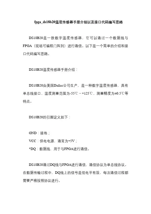
fpga_ds18b20温度传感器手册介绍以及接口代码编写思路DS18B20是一款数字温度传感器,它可以通过一个数据线与FPGA(现场可编程门阵列)进行通信。
以下是一个简单的介绍和接口代码编写思路。
DS18B20温度传感器手册介绍:DS18B20由美国Dallas公司生产,是一种数字温度传感器,具有单总线接口、温度测量范围为-55℃~+125℃、测量精度为±0.5℃等特点。
DS18B20的引脚定义如下:GND:接地;VCC:供电电源,通常为+5V;*DQ:数据线,用于与FPGA进行通信。
DS18B20通过DQ线与FPGA进行通信,通信协议为单总线协议。
在数据传输过程中,DQ线上的信号是低电平有效,每次通信过程都需要严格按照协议进行。
DS18B20的测温原理是利用内部的振荡器产生一个频率与温度成正比的脉冲信号,通过计数器计数来测量温度值。
接口代码编写思路:初始化DS18B20和FPGA的DQ线。
在初始化过程中,需要设置DQ线的输入/输出模式,并确保DQ线处于空闲状态。
发送DS18B20的初始化命令序列。
DS18B20需要先执行一系列初始化命令,包括选择温度分辨率、启动温度转换等。
这些命令可以通过向DQ线发送特定的序列来实现。
等待DS18B20的温度转换完成。
在DS18B20完成温度转换之前,DQ线处于空闲状态。
当温度转换完成后,DS18B20会通过DQ线发送一个低电平信号,表示可以读取温度值。
读取DS18B20的温度值。
通过向DQ线发送读取命令序列,可以读取DS18B20的温度值。
温度值以二进制补码的形式发送,需要通过代码进行解码并转换为实际温度值。
结束通信并释放资源。
在读取完温度值后,需要向DQ线发送一个复位序列来结束通信,并释放相关资源。
在实际编写代码时,需要注意以下几个问题:保证DQ线的稳定性和可靠性,避免因干扰或信号不稳定导致通信失败或数据错误;严格按照DS18B20的通信协议进行数据传输,确保数据正确无误;对读取的温度值进行校验和处理,以避免异常数据对系统造成影响。
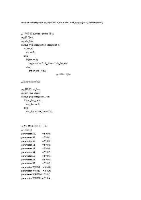
module temper(input clk,input rst_n,inout one_wire,output [15:0] temperature);// 分频器20MHz->1MHz 开始reg [3:0] cnt;reg clk_1us;always @ (posedge clk, negedge rst_n)if (!rst_n)cnt <= 0;elseif (cnt == 9)begin cnt <= 0;clk_1us<= ~ clk_1us;endelsecnt <= cnt + 4'd1;// 1MHz 时钟//延时模块的使用reg [19:0] cnt_1us;reg cnt_1us_clear;always @ (posedge clk_1us)if (cnt_1us_clear)cnt_1us <= 0;elsecnt_1us <= cnt_1us + 1'b1;// DS18B20状态机开始// 格雷码parameter S00 = 5'h00;parameter S0 = 5'h01;parameter S1 = 5'h03;parameter S2 = 5'h02;parameter S3 = 5'h06;parameter S4 = 5'h07;parameter S5 = 5'h05;parameter S6 = 5'h04;parameter S7 = 5'h0C;parameter WRITE0 = 5'h0D;parameter WRITE1 = 5'h0F;parameter WRITE00 = 5'h0E;parameter WRITE01 = 5'h0A;parameter READ0 = 5'h0B;parameter READ1 = 5'h09;parameter READ2 = 5'h08;parameter READ3 = 5'h18;reg [4:0] state; // 状态寄存器//-------------------------------------reg one_wire_buf; // One-Wire总线缓存寄存器reg [15:0] temperature_buf; // 采集到的温度值缓存器reg [5:0] step; // 子状态寄存器0~50reg [3:0] bit_valid; // 有效位always @(posedge clk_1us, negedge rst_n)beginif (!rst_n)beginone_wire_buf <= 1'bZ;step <= 0;state <= S00;endelsebegincase (state)S00 : begintemperature_buf <= 16'h001F;state <= S0;endS0 : begin // 初始化cnt_1us_clear <= 1;one_wire_buf <= 0;state <= S1;endS1 : begincnt_1us_clear <= 0;if (cnt_1us == 500) // 延时500usbegincnt_1us_clear <= 1;one_wire_buf <= 1'bZ; // 释放总线state <= S2;endendS2 : begincnt_1us_clear <= 0;if (cnt_1us == 100) // 等待100usbegincnt_1us_clear <= 1;state <= S3;endendS3 : if (~one_wire) // 若18b20拉低总线,初始化成功state <= S4;else if (one_wire) // 否则,初始化不成功,返回S0state <= S0;S4 : begincnt_1us_clear <= 0;if (cnt_1us == 400) // 再延时400usbegincnt_1us_clear <= 1;state <= S5;endendS5 : begin // 写数据if (step == 0) // 0xCCbeginstep <= step + 1'b1;state <= WRITE0;endelse if (step == 1)beginstep <= step + 1'b1;state <= WRITE0;endelse if (step == 2)beginone_wire_buf <= 0;step <= step + 1'b1;state <= WRITE01;endelse if (step == 3)beginone_wire_buf <= 0;step <= step + 1'b1;state <= WRITE01;endelse if (step == 4)beginstep <= step + 1'b1;endelse if (step == 5)beginstep <= step + 1'b1;state <= WRITE0;endelse if (step == 6)beginone_wire_buf <= 0;step <= step + 1'b1; state <= WRITE01; endelse if (step == 7)beginone_wire_buf <= 0;step <= step + 1'b1; state <= WRITE01; endelse if (step == 8) // 0x44 beginstep <= step + 1'b1;state <= WRITE0;endelse if (step == 9)beginstep <= step + 1'b1;state <= WRITE0;endelse if (step == 10)beginone_wire_buf <= 0;step <= step + 1'b1; state <= WRITE01; endelse if (step == 11)beginstep <= step + 1'b1;state <= WRITE0;endelse if (step == 12)beginstep <= step + 1'b1;endelse if (step == 13)beginstep <= step + 1'b1;state <= WRITE0;endelse if (step == 14)beginone_wire_buf <= 0;step <= step + 1'b1; state <= WRITE01;endelse if (step == 15)beginstep <= step + 1'b1;state <= WRITE0;end// 第一次写完,750ms后,跳回S0 else if (step == 16)beginone_wire_buf <= 1'bZ;step <= step + 1'b1; state <= S6;endelse if (step == 17) // 0xCC beginstep <= step + 1'b1;state <= WRITE0;endelse if (step == 18)beginstep <= step + 1'b1;state <= WRITE0;endelse if (step == 19)beginone_wire_buf <= 0;step <= step + 1'b1; state <= WRITE01; endbeginstep <= step + 1'b1;state <= WRITE01;one_wire_buf <= 0;endelse if (step == 21)beginstep <= step + 1'b1;state <= WRITE0;endelse if (step == 22)beginstep <= step + 1'b1;state <= WRITE0;endelse if (step == 23)beginone_wire_buf <= 0;step <= step + 1'b1; state <= WRITE01; endelse if (step == 24)beginone_wire_buf <= 0;step <= step + 1'b1; state <= WRITE01; endelse if (step == 25) // 0xBE beginstep <= step + 1'b1;state <= WRITE0;endelse if (step == 26)beginone_wire_buf <= 0;step <= step + 1'b1; state <= WRITE01; endelse if (step == 27)beginone_wire_buf <= 0;step <= step + 1'b1;state <= WRITE01;endelse if (step == 28)beginone_wire_buf <= 0;step <= step + 1'b1;state <= WRITE01;endelse if (step == 29)beginone_wire_buf <= 0;step <= step + 1'b1;state <= WRITE01;endelse if (step == 30)beginone_wire_buf <= 0;step <= step + 1'b1;state <= WRITE01;endelse if (step == 31)beginstep <= step + 1'b1;state <= WRITE0;endelse if (step == 32)beginone_wire_buf <= 0;step <= step + 1'b1;state <= WRITE01;end// 第二次写完,跳到S7,直接开始读数据else if (step == 33)beginstep <= step + 1'b1;state <= S7;endendS6 : begincnt_1us_clear <= 0;if (cnt_1us == 750000 | one_wire) // 延时750msbegincnt_1us_clear <= 1;state <= S0; // 跳回S0,再次初始化endendS7 : begin // 读数据if (step == 34)beginbit_valid <= 0;one_wire_buf <= 0;step <= step + 1'b1;state <= READ0;endelse if (step == 35)beginbit_valid <= bit_valid + 1'b1;one_wire_buf <= 0;step <= step + 1'b1;state <= READ0;endelse if (step == 36)beginbit_valid <= bit_valid + 1'b1;one_wire_buf <= 0;step <= step + 1'b1;state <= READ0;endelse if (step == 37)beginbit_valid <= bit_valid + 1'b1;one_wire_buf <= 0;step <= step + 1'b1;state <= READ0;endelse if (step == 38)beginbit_valid <= bit_valid + 1'b1;one_wire_buf <= 0;step <= step + 1'b1;state <= READ0;endelse if (step == 39)beginbit_valid <= bit_valid + 1'b1;one_wire_buf <= 0;step <= step + 1'b1; state <= READ0;endelse if (step == 40)beginbit_valid <= bit_valid + 1'b1; one_wire_buf <= 0;step <= step + 1'b1; state <= READ0;endelse if (step == 41)beginbit_valid <= bit_valid + 1'b1; one_wire_buf <= 0;step <= step + 1'b1; state <= READ0;endelse if (step == 42)beginbit_valid <= bit_valid + 1'b1; one_wire_buf <= 0;step <= step + 1'b1; state <= READ0;endelse if (step == 43)beginbit_valid <= bit_valid + 1'b1; one_wire_buf <= 0;step <= step + 1'b1; state <= READ0;endelse if (step == 44)beginbit_valid <= bit_valid + 1'b1; one_wire_buf <= 0;step <= step + 1'b1; state <= READ0;endelse if (step == 45)beginbit_valid <= bit_valid + 1'b1; one_wire_buf <= 0;step <= step + 1'b1; state <= READ0;endelse if (step == 46)beginbit_valid <= bit_valid + 1'b1;one_wire_buf <= 0;step <= step + 1'b1;state <= READ0;endelse if (step == 47)beginbit_valid <= bit_valid + 1'b1;one_wire_buf <= 0;step <= step + 1'b1;state <= READ0;endelse if (step == 48)beginbit_valid <= bit_valid + 1'b1;one_wire_buf <= 0;step <= step + 1'b1;state <= READ0;endelse if (step == 49)beginbit_valid <= bit_valid + 1'b1;one_wire_buf <= 0;step <= step + 1'b1;state <= READ0;endelse if (step == 50)beginstep <= 0;state <= S0;endend// 写0.1WRITE0 :begincnt_1us_clear <= 0;one_wire_buf <= 0; // 输出0if (cnt_1us == 80) // 延时80usbeginone_wire_buf <= 1'bZ; // 释放总线,自动拉高state <= WRITE00;endendWRITE00 : // 空状态state <= S5;WRITE01 : // 空状态state <= WRITE1;WRITE1 :begincnt_1us_clear <= 0;one_wire_buf <= 1'bZ; // 输出1 释放总线,自动拉高if (cnt_1us == 80) // 延时80usbegincnt_1us_clear <= 1;state <= S5;endend// 读0READ0 : state <= READ1; // 空延时状态READ1 :begincnt_1us_clear <= 0;one_wire_buf <= 1'bZ; // 释放总线if (cnt_1us == 10) // 再延时10usbegincnt_1us_clear <= 1;state <= READ2;endendREAD2 : // 读取数据begintemperature_buf[bit_valid] <= one_wire;state <= READ3;endREAD3 :begincnt_1us_clear <= 0;if (cnt_1us == 55) // 再延时55usbegincnt_1us_clear <= 1;endend// 读状态机default : state <= S00;endcaseendendassign one_wire = one_wire_buf; // 注意双向口的使用(cichuzhuyaoyongyushurushuju)// DS18B20状态机结束// 对采集到的温度进行处理开始wire [15:0] t_buf = temperature_buf & 16'h07FF;assign temperature[3:0] = (t_buf[3:0] * 10) >> 4; // 小数点后一位assign temperature[7:4] = (t_buf[7:4] >= 10) ? (t_buf[7:4] - 10) : t_buf[7:4]; // 个位assign temperature[11:8] = (t_buf[7:4] >= 10) ? (t_buf[11:8] + 1) : t_buf[11:8]; // 十位endmodule。
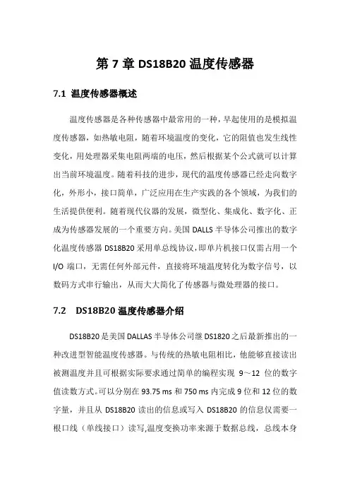
第7章DS18B20温度传感器7.1 温度传感器概述温度传感器是各种传感器中最常用的一种,早起使用的是模拟温度传感器,如热敏电阻,随着环境温度的变化,它的阻值也发生线性变化,用处理器采集电阻两端的电压,然后根据某个公式就可以计算出当前环境温度。
随着科技的进步,现代的温度传感器已经走向数字化,外形小,接口简单,广泛应用在生产实践的各个领域,为我们的生活提供便利。
随着现代仪器的发展,微型化、集成化、数字化、正成为传感器发展的一个重要方向。
美国DALLS半导体公司推出的数字化温度传感器DS18B20采用单总线协议,即单片机接口仅需占用一个I/O端口,无需任何外部元件,直接将环境温度转化为数字信号,以数码方式串行输出,从而大大简化了传感器与微处理器的接口。
7.2 DS18B20温度传感器介绍DS18B20是美国DALLAS半导体公司继DS1820之后最新推出的一种改进型智能温度传感器。
与传统的热敏电阻相比,他能够直接读出被测温度并且可根据实际要求通过简单的编程实现9~12位的数字值读数方式。
可以分别在93.75 ms和750 ms内完成9位和12位的数字量,并且从DS18B20读出的信息或写入DS18B20的信息仅需要一根口线(单线接口)读写,温度变换功率来源于数据总线,总线本身也可以向所挂接的DS18B20供电,而无需额外电源。
因而使用DS18B20可使系统结构更趋简单,可靠性更高。
他在测温精度、转换时间、传输距离、分辨率等方面较DS1820有了很大的改进,给用户带来了更方便的使用和更令人满意的效果。
1.DS18B20温度传感器的特性①独特的单线接口方式:DS18B20与微处理器连接时仅需要一条口线即可实现微处理器与DS18B20的双向通讯。
②在使用中不需要任何外围元件。
③可用数据线供电,电压范围:+3.0~ +5.5 V。
④测温范围:-55 ~+125 ℃。
固有测温分辨率为0.5 ℃。
⑤通过编程可实现9~12位的数字读数方式。
数字温度传感器DS18B20中文资料(含读写程序)数字温度传感器__中文资料(含读写程序)的学习供参考数字温度传感器__中文资料(含读写程序)__特点1.单线结构,只需一根信号线和CPU相连。
2. 不需要外部元件,直接输出串行数据。
3. 可不需要外部电源,直接通过信号线供电,电源电压范围为3.3V~5V。
4.测温精度高,测温范围为:一55℃~+125℃,在-10℃~+85℃范围内,精度为±O.5℃。
5.测温分辨率高,当选用12位转换位数时,温度分辨率可达0.0625℃。
6.数字量的转换精度及转换时间可通过简单的编程来控制:9位精度的转换时间为93.75 ms:10位精度的转换时间187.5ms:12位精度的转换时间750ms。
7.具有非易失性上、下限报警设定的功能,用户可方便地通过编程修改上、下限的数值。
8.可通过报警搜索命令识别哪片DS__采集的温度超越上、下限。
__引脚及管脚功能介绍__的常用封装有3脚、8脚等几种形式,如图1所示。
各脚含义如下:DQ:数字信号输入/输出端。
GND:电源地端。
VDD:外接供电电源输入端(在寄生电源接线时此脚应接地)。
__内部结构简要介绍:DS__的内部结构如图3所示:主要有64位光刻ROM、温度传感器、非易失性温度报警触发器TH和TL、配置寄存器等组成。
1.64位光刻ROM是生产厂家给每一个出厂的DS__命名的产品序列号,可以看作为该器件的地址序列号。
其作用是使每一个出厂的DS__地址序列号都各不相同,这样,就可以实现一根总线上挂接多个DS__的目的。
2.DS__中的温度传感器完成对温度的测量,输出格式为:16位符号扩展的二进制补码。
当测温精度设置为12位时,分辨率为O.0625℃,即O.0625℃/LSB。
其二进制补码格式如图2所示。
其中,S为符号位,S=1,表示温度为负值;S=0,表示温度为正值。
例如+125℃的数字输出为07D0H,-55℃的数字输出为FC90H。
基于FPGA的DS18B20控制程序设计及其Verilog实现一,总体介绍DS18B20是一个1-wire总线,12bit的数字温度传感器,其详细的参数这里不做具体的介绍,只讨论其基于Verilog的控制程序的设计。
实际上,对DS18B20的控制,主要是实现1-wire总线的初始化,读,写等操作,然后再根据DS18B20的控制要求,实现对其控制的verilog逻辑。
在1-Wire总线上,有一个master,可以有1个或者多个slave。
而对于FPGA+DS18B20的温度测试设计来讲,需要在FPGA上实现一个1-Wire总线的master。
DS18B20作为1-wire 总线的slave设备存在,可以有一个或者多个,不过为了简化程序,例程里假定只存在一个DS18B2020。
1-Wire总线的操作形式上相对简单,但操作本身相对却又比较复杂。
用Verilog做控制程序设计时,可以采用多层次嵌套的状态机来实现。
二,FPGA + DS18B20的硬件设计硬件的设计非常简单,只需要将DS18B20的DQ与FPGA的一个IO连接,并加4.7K左右的上拉电阻就可以了。
VDD和VPU可以为3.0~5.0V。
这里我们参照FPGA本身的IO电压,选择3.3V。
另外要注意的一点是,由于DQ的数据是双向的,所以FPGA的该IO要设定为inout类型。
三,1-Wire总线的基本操作及Verilog实现。
根据1-Wire总线的特点,可以把1-Wire总线的操作归结为初始化,单bit读操作,单bit写操作等最基础的几种。
下面分别是几种基本操作的介绍和verilog实现。
由于DS18B20的时序操作的最小单位基本上是1us,所以在该设计中,全部采用1MHz的时钟。
1. 初始化初始化实际上就是1-wire总线上的Reset操作。
由master发出一定长度的初始化信号。
Slave 看到该初始化信号后,在一定时间内发出规定长度的响应信号,然后初始化操作就结束了。
1.编写的程序(一)功能模块:library ieee;use ieee.std_logic_1164.all;use ieee.std_logic_unsigned.all;use ieee.std_logic_arith.all;--实体--entity at24c08 isport(clk : in std_logic; --时钟信号rst : in std_logic; --复位信号scl : out std_logic; --i2c时钟线sda : inout std_logic; --i2c数据线urv_1 : in std_logic; --上限值1urv_2 : in std_logic; --上限值2sel : out std_logic_vector(3 downto 0);seg : out std_logic_vector(7 downto 0);beep : out std_logic --蜂鸣器输出信号线);end at24c08;--结构体--architecture arch_at24c08 of at24c08 issignal clk_sslow : std_logic;signal counter : std_logic_vector(23 downto 0);signal readdata_reg_buf : std_logic_vector(15 downto 0);signal readdata_ten : integer range 0 to 24564;signal readdata_std : std_logic_vector(15 downto 0);signal qian : std_logic_vector(3 downto 0);signal bai : std_logic_vector(3 downto 0);signal shi : std_logic_vector(3 downto 0);signal ge : std_logic_vector(3 downto 0);signal qian_0 : integer range 0 to 10;signal bai_0 : integer range 0 to 10;signal shi_0 : integer range 0 to 10;signal ge_0 : integer range 0 to 10;--数码管部分信号signal sel_0 : std_logic_vector(3 downto 0);signal seg_0 : std_logic_vector(7 downto 0);signal count : std_logic_vector(13 downto 0);signal clk_slow : std_logic;signal scan_num : std_logic_vector(1 downto 0);signal seg_data_buf : std_logic_vector(3 downto 0);--i2c部分信号signal sda_buf : std_logic; --i2c输入/输出数据寄存器signal link : std_logic; --sda输入输出方向寄存器signal readdata_reg : std_logic_vector(15 downto 0);--i2c读回的数据寄存器signal sda_0 : std_logic; --与sda端口连接信号signal scl_0 : std_logic; --与scl端口连接信号--按键消抖部分信号signal delay_cnt : std_logic_vector(19 downto 0); --消抖延时计数器signal start_delay : std_logic; --按键延时开始--分频部分信号signal clk_div : std_logic_vector(12 downto 0); --分频计数器,5000分频,10khz--蜂鸣器部分信号signal beep_en : std_logic; --蜂鸣器使能信号signal beep_buf : std_logic; --与beep端口连接的信号--时钟部分信号signal level_high : std_logic; --高电平中间值,1249 signal level_low : std_logic; --低电平中间值,3749 signal level_hig_edge : std_logic; --上升沿,4999signal level_low_edge : std_logic; --下降沿,2499--状态机部分信号signal main_state : std_logic_vector(1 downto 0); --状态机主状态signal i2c_state : std_logic_vector(2 downto 0); --i2c状态signal i2c_per_state : std_logic_vector(3 downto 0); --i2c每一步状态--分频部分常量constant div_parameter : std_logic_vector(12 downto 0):="1001110001000";--分频系数,500--状态机部分常量--操作状态常量constant read_init : std_logic_vector(2 downto 0) :="000";--EEPORM 初始化constant read_high : std_logic_vector(2 downto 0) :="001";--读高位数据状态constant read_low : std_logic_vector(2 downto 0) :="010";--读低位数据状态--i2c每一步状态常量constant start : std_logic_vector(3 downto 0) :="0000";--开始位constant first : std_logic_vector(3 downto 0) :="0001";--数据第一位constant second : std_logic_vector(3 downto 0) :="0010";--数据第二位constant third : std_logic_vector(3 downto 0) :="0011";--数据第三位constant fourth : std_logic_vector(3 downto 0) :="0100";--数据第四位constant fifth : std_logic_vector(3 downto 0) :="0101";--数据第五位constant sixth : std_logic_vector(3 downto 0) :="0110";--数据第六位constant seventh : std_logic_vector(3 downto 0) :="0111";--数据第七位constant eighth : std_logic_vector(3 downto 0) :="1000";--数据第八位constant ack : std_logic_vector(3 downto 0) :="1001";--应答位constant stop : std_logic_vector(3 downto 0) :="1010";--停止位--结构体开始beginscl <= scl_0;seg <= seg_0;sda_0 <= sda_buf when (link)='1' else 'Z';sda <= sda_0;sel <= sel_0;beep <= beep_buf;--按键消抖key : process(clk,rst)beginif(not rst='1') thendelay_cnt <= (others => '0');elsif (clk'event and clk='1') thenif start_delay='1' thenif(delay_cnt /= "11110100001001000000") then --20ms延时delay_cnt <= delay_cnt+'1';elsedelay_cnt <= (others => '0');end if;end if;end if;end process key;--分频部分div : process(rst,clk)beginif(not rst='1') thenclk_div <= "0000000000000";level_high <= '0';level_low <= '0';level_hig_edge <= '0';level_low_edge <= '0';elsif(clk'event and clk='1') thenif(clk_div /= div_parameter-'1') then clk_div <= clk_div+'1';elseclk_div <= "0000000000000";end if;if(level_high='1') thenlevel_high <= '0';elseif(clk_div="10011100001") thenlevel_high <= '1';end if;end if;if(level_low_edge='1') thenlevel_low_edge <= '0';elseif(clk_div="100111000011") thenlevel_low_edge <= '1';end if;end if;if(level_low='1') thenlevel_low <= '0';elseif(clk_div="111010100101") thenlevel_low <= '1';end if;end if;if(level_hig_edge='1') thenlevel_hig_edge <= '0';elseif(clk_div="1001110000111") thenlevel_hig_edge <= '1';end if;end if;end if;end process div;--EEPROM操作部分state : process(clk,rst)beginif(not rst='1') thenstart_delay <= '0';scl_0 <= '1';sda_buf <= '1';link <= '0';readdata_reg <= "0000000000000000";main_state <= "00";i2c_state <= read_init;i2c_per_state <= start;elsif(clk'event and clk='1') thencase main_state is--初始化EEPROMwhen "00" =>--等待读写要求scl_0 <= '1';sda_buf <= '1';link <= '0';i2c_state <= read_init;i2c_per_state <= start;main_state <= "10";--读取EEPRO数据when "10" =>if(level_hig_edge='1') thenscl_0 <= '1';elseif(level_low_edge='1') thenscl_0 <= '0';end if;end if;case i2c_state iswhen read_init => --读命令地址case i2c_per_state iswhen start =>if(level_high='1') thensda_buf <= '0';link <= '1';end if;if((level_low and link)='1') thenlink <= '1';sda_buf <= '1';i2c_per_state <= first;end if;when first =>if(level_low='1') thensda_buf <= '0';i2c_per_state <= second;end if;when second =>if(level_low='1') thensda_buf <= '0';link <= '1';i2c_per_state <= third;end if;when third =>if(level_low='1') thensda_buf <= '1';link <= '1';i2c_per_state <= fourth;end if;when fourth =>if(level_low='1') thensda_buf <= '0';link <= '1';i2c_per_state <= fifth;end if;when fifth =>if(level_low='1') thensda_buf <= '0';link <= '1';i2c_per_state <= sixth;end if;when sixth =>if(level_low='1') thensda_buf <= '0';i2c_per_state <= seventh;end if;when seventh =>if(level_low='1') thensda_buf <= '1';link <= '1';i2c_per_state <= eighth;end if;when eighth =>if(level_low='1') thenlink <= '0';i2c_per_state <= ack;end if;when ack =>if(level_hig_edge='1') thensda_buf <= sda;end if;if(level_high='1') thenif(sda_buf='1') thenmain_state <= "00";end if;end if;if(level_low='1') thenlink <= '0';i2c_state <= read_high;i2c_per_state <= first;end if;when others => null;end case;when read_high => --读回数据case i2c_per_state iswhen first =>if(level_hig_edge='1') thensda_buf <= sda;end if;if(level_high='1') thenreaddata_reg(15 downto 9) <= readdata_reg(14 downto 8);readdata_reg(8) <= sda;end if;if(level_low='1') theni2c_per_state <= second;end if;when second =>if(level_hig_edge='1') thensda_buf <= sda;end if;if(level_high='1') thenreaddata_reg(15 downto 9) <= readdata_reg(14 downto 8);readdata_reg(8) <= sda;end if;if(level_low='1') theni2c_per_state <= third;end if;when third =>if(level_hig_edge='1') thensda_buf <= sda;end if;if(level_high='1') thenreaddata_reg(15 downto 9) <= readdata_reg(14 downto 8);readdata_reg(8) <= sda;end if;if(level_low='1') theni2c_per_state <= fourth;end if;when fourth =>if(level_hig_edge='1') thensda_buf <= sda;end if;if(level_high='1') thenreaddata_reg(15 downto 9) <= readdata_reg(14 downto 8);readdata_reg(8) <= sda;end if;if(level_low='1') theni2c_per_state <= fifth;end if;when fifth =>if(level_hig_edge='1') thensda_buf <= sda;end if;if(level_high='1') thenreaddata_reg(15 downto 9) <= readdata_reg(14 downto 8);readdata_reg(8) <= sda;end if;if(level_low='1') theni2c_per_state <= sixth;end if;when sixth =>if(level_hig_edge='1') thensda_buf <= sda;end if;if(level_high='1') thenreaddata_reg(15 downto 9) <= readdata_reg(14 downto 8);readdata_reg(8) <= sda;end if;if(level_low='1') theni2c_per_state <= seventh;end if;when seventh =>if(level_hig_edge='1') thensda_buf <= sda;end if;if(level_high='1') thenreaddata_reg(15 downto 9) <= readdata_reg(14 downto 8);readdata_reg(8) <= sda;end if;if(level_low='1') theni2c_per_state <= eighth;end if;when eighth =>if(level_hig_edge='1') thensda_buf <= sda;end if;if(level_high='1') thenreaddata_reg(15 downto 9) <= readdata_reg(14 downto 8);readdata_reg(8) <= sda;end if;if(level_low='1') theni2c_per_state <= ack;end if;when ack =>if(level_high='1') thenlink <= '1';sda_buf <= '0';i2c_per_state <= first;i2c_state <= read_low;end if;when others => null;end case;when read_low =>case i2c_per_state iswhen first =>if(level_hig_edge='1') thenlink <= '0';sda_buf <= sda;end if;if(level_high='1') thenreaddata_reg(7 downto 1) <= readdata_reg(6 downto 0);readdata_reg(0) <= sda;end if;if(level_low='1') theni2c_per_state <= second;end if;when second =>if(level_hig_edge='1') thenlink <= '0';sda_buf <= sda;end if;if(level_high='1') thenreaddata_reg(7 downto 1) <= readdata_reg(6 downto 0);readdata_reg(0) <= sda;end if;if(level_low='1') theni2c_per_state <= third;end if;when third =>if(level_hig_edge='1') thenlink <= '0';sda_buf <= sda;end if;if(level_high='1') thenreaddata_reg(7 downto 1) <= readdata_reg(6 downto 0);readdata_reg(0) <= sda;end if;if(level_low='1') theni2c_per_state <= fourth;end if;when fourth =>if(level_hig_edge='1') thenlink <= '0';sda_buf <= sda;end if;if(level_high='1') thenreaddata_reg(7 downto 1) <= readdata_reg(6 downto 0);readdata_reg(0) <= sda;end if;if(level_low='1') theni2c_per_state <= fifth;end if;when fifth =>if(level_hig_edge='1') thenlink <= '0';sda_buf <= sda;end if;if(level_high='1') thenreaddata_reg(7 downto 1) <= readdata_reg(6 downto 0);readdata_reg(0) <= sda;end if;if(level_low='1') theni2c_per_state <= sixth;end if;when sixth =>if(level_hig_edge='1') thenlink <= '0';sda_buf <= sda;end if;if(level_high='1') thenreaddata_reg(7 downto 1) <= readdata_reg(6 downto 0);readdata_reg(0) <= sda;end if;if(level_low='1') theni2c_per_state <= seventh;end if;when seventh =>if(level_hig_edge='1') thenlink <= '0';sda_buf <= sda;end if;if(level_high='1') thenreaddata_reg(7 downto 1) <= readdata_reg(6 downto 0);readdata_reg(0) <= sda;end if;if(level_low='1') theni2c_per_state <= eighth;end if;when eighth =>if(level_hig_edge='1') thenlink <= '0';sda_buf <= sda;end if;if(level_high='1') thenreaddata_reg(7 downto 1) <= readdata_reg(6 downto 0);readdata_reg(0) <= sda;end if;if(level_low='1') theni2c_per_state <= ack;end if;when ack =>if(level_high='1') thenlink <= '1';sda_buf <= '1'; --非应答位-- i2c_per_state <= stop;end if;if(level_low='1') thenlink <= '1';sda_buf <= '0';i2c_per_state <= stop;end if;when stop =>if(level_high='1') thenlink <= '1';sda_buf <= '1'; --停止位end if;if(level_low='1') thenmain_state <= "00";end if;when others => null;end case;when others => null;end case;when others => null;end case;end if;end process state;--数据处理部分anly1 : process(readdata_reg_buf)beginreaddata_ten <= conv_integer(readdata_reg_buf)*12;qian_0 <= readdata_ten/1000;bai_0 <= (readdata_ten/100) rem 10;shi_0 <= (readdata_ten/10) rem 10;ge_0 <= readdata_ten rem 10;end process anly1;anly2 : process(qian_0,bai_0,shi_0,ge_0)beginqian <= conv_std_logic_vector(qian_0,4);bai <= conv_std_logic_vector(bai_0,4);shi <= conv_std_logic_vector(shi_0,4);ge <= conv_std_logic_vector(ge_0,4);end process anly2;--数码管显示部分scan : process(rst,clk)beginif(not rst='1') thencount <= (others => '0');clk_slow <= '0';elsif(clk'event and clk='1') thenif(count="11111011011111") thencount <= (others => '0');clk_slow <= not clk_slow;elsecount <= count + '1';end if;end if;end process scan;seg1 : process(clk_slow,rst)beginif(not rst='1') thenscan_num <= "00";elsif(clk_slow'event and clk_slow='1') thenif(scan_num="11") thenscan_num <= "00";elsescan_num <= scan_num + '1';end if;end if;end process seg1;seg2 : process(seg_data_buf)begincase seg_data_buf iswhen "1111" => seg_0 <= "10001110";when "1110" => seg_0 <= "10000110"; when "1101" => seg_0 <= "10100001";when "1100" => seg_0 <= "11000110";when "1011" => seg_0 <= "10000011";when "1010" => seg_0 <= "10011000";when "1001" => seg_0 <= "10010000";when "1000" => seg_0 <= "10000000"; when "0111" => seg_0 <= "11111000"; when "0110" => seg_0 <= "10000010"; when "0101" => seg_0 <= "10010010"; when "0100" => seg_0 <= "10011001"; when "0011" => seg_0 <= "10110000"; when "0010" => seg_0 <= "10100100"; when "0001" => seg_0 <= "11111001"; when "0000" => seg_0 <= "11000000"; when others => seg_0 <= "11111111";end case;end process seg2;seg0 : process(scan_num)begincase scan_num iswhen "00" =>sel_0 <= "1110";seg_data_buf <= ge;when "01" =>sel_0 <= "1101";seg_data_buf <= shi;when "10" =>sel_0 <= "1011";seg_data_buf <= bai;when "11" =>sel_0 <= "0111";seg_data_buf <= qian;when others => null;end case;end process seg0;--数据缓存部分ss : process(clk,rst)beginif(not rst='1') thenclk_sslow <= '0';counter <= (others => '0');elsif(clk'event and clk='1') thenif(counter /= "111111111111111111111110") then counter <= counter + '1';elsecounter <= (others => '0');clk_sslow <= not clk_sslow;end if;end if;end process ss;buf : process(clk_sslow)beginif(clk_sslow'event and clk_sslow='1') thenreaddata_reg_buf <= readdata_reg;elsereaddata_reg_buf <= readdata_reg_buf;end if;end process buf;--蜂鸣器报警部分bep : process(clk,rst)variable count : integer range 0 to 50000; --1KHz方波beginif(not rst='1') thencount := 0;beep_en <= '0';elsif(clk'event and clk='1') thenif(beep_en='1') thencount := count+1;if(count>50000) thencount := 0;beep_buf <= not beep_buf;end if;elseif(not urv_1='1') thenif(readdata_reg>"0000000000000011") thenbeep_en <= '1';end if;elsif(not urv_2='1') thenif(readdata_reg>"1111111111100000") thenbeep_en <= '1';end if;end if;end if;end if;end process bep;end arch_at24c08;(二)测试模块:library ieee;use ieee.std_logic_1164.all;use ieee.std_logic_unsigned.all;use ieee.std_logic_arith.all;entity tb is--null;end tb;architecture behv_tb of tb iscomponent at24c08port(clk : in std_logic; --时钟信号rst : in std_logic; --复位信号scl : out std_logic; --i2c时钟线sda : inout std_logic; --i2c数据线urv_1 : in std_logic; --上限值1urv_2 : in std_logic; --上限值2sel : out std_logic_vector(3 downto 0);seg : out std_logic_vector(7 downto 0);beep : out std_logic --蜂鸣器输出信号线);end component;constant clockperiod : time := 20ns;signal clk_tb : std_logic := '0';signal rst_tb : std_logic;signal scl_tb : std_logic;signal sda_tb : std_logic;signal urv_1_tb : std_logic;signal urv_2_tb : std_logic;signal sel_tb : std_logic_vector(3 downto 0);signal seg_tb : std_logic_vector(7 downto 0);signal beep_tb : std_logic;beginmyuit : at24c08 port map(clk => clk_tb,rst => rst_tb,scl => scl_tb,sda => sda_tb,urv_1 => urv_1_tb,urv_2 => urv_2_tb,sel => sel_tb,seg => seg_tb,beep => beep_tb);process(clk_tb)beginclk_tb <= not clk_tb after clockperiod/2;end process;rst_tb <= ‘0',‘1' after 1000ns;end behv_tb;。
18B20温度传感器的读显一,电路二,PCB三,实物四,程序//DS18B20的读写程序,数据脚P2.4 ////温度传感器18B20汇编程序,采用器件默认的12位转化// //最大转化时间750微秒,显示温度-55到+125度,显示精度////为0.1度,显示采用4位LED共阳显示测温值// //P1口为段码输入,P20~P23为位选// /***************************************************/#include "reg51.h"#include "intrins.h" //_nop_();延时函数用#define Disdata P0 //段码输出口#define discan P2 //扫描口#define uchar unsigned char#define uint unsigned intsbit DQ=P2^4; //温度输入口sbit DIN=P0^7; //LED小数点控制uint h;uchar flag;//**************温度小数部分用查表法***********//uchar code ditab[16]={0x00,0x01,0x01,0x02,0x03,0x03,0x04,0x04,0x05,0x06,0x06,0x07,0x08,0x08,0x09, 0x09};//uchar codedis_7[12]={0xc0,0xf9,0xa4,0xb0,0x99,0x92,0x82,0xf8,0x80,0x90,0xff,0xbf};//共阳LED段码表"0" "1" "2" "3" "4" "5" "6" "7" "8" "9" "不亮" "-"//uchar code scan_con[4]={0x8f,0x4f,0x2f,0x1f}; //列扫描控制字uchar code scan_con[4]={0xf7,0xfb,0xfd,0xfe};uchar data temp_data[2]={0x00,0x00}; //读出温度暂放uchar data display[5]={0x00,0x00,0x00,0x00,0x00}; //显示单元数据,共4个数据和一个运算暂用///////***********11微秒延时函数**********///void delay(uint t){for(;t>0;t--);}///***********显示扫描函数**********/scan(){char k;for(k=0;k<4;k++) //四位LED扫描控制{Disdata=0xff;Disdata=dis_7[display[k]];if(k==1){DIN=0;}discan=scan_con[k];delay(90);discan=0xff;}}/////***********18B20复位函数**********/ow_reset(void){char presence=1;while(presence){while(presence){DQ=1;_nop_();_nop_();DQ=0; //delay(50); // 550usDQ=1; //delay(6); // 66uspresence=DQ; // presence=0继续下一步}delay(45); //延时500uspresence = ~DQ;}DQ=1;}/////**********18B20写命令函数*********///向1-WIRE 总线上写一个字节void write_byte(uchar val){uchar i;for (i=8; i>0; i--) //{DQ=1;_nop_();_nop_();DQ = 0;_nop_();_nop_();_nop_();_nop_();_nop_();//5us DQ = val&0x01; //最低位移出delay(6); //66usval=val/2; //右移一位}DQ = 1;delay(1);}///*********18B20读1个字节函数********///从总线上读取一个字节uchar read_byte(void){uchar i;uchar value = 0;for (i=8;i>0;i--){DQ=1;_nop_();_nop_();value>>=1;DQ = 0; //_nop_();_nop_();_nop_();_nop_(); //4usDQ = 1;_nop_();_nop_();_nop_();_nop_(); //4us if(DQ)value|=0x80;delay(6); //66us}DQ=1;return(value);}///***********读出温度函数**********///read_temp(){ow_reset(); //总线复位write_byte(0xCC); // 发Skip ROM命令write_byte(0xBE); // 发读命令temp_data[0]=read_byte(); //温度低8位temp_data[1]=read_byte(); //温度高8位ow_reset();write_byte(0xCC); // Skip ROMwrite_byte(0x44); // 发转换命令}///***********温度数据处理函数**********/ void work_temp(){uchar n=0;uchar doth,dotl;uchar flag3=1,flag2=1; //数字显示修正标记if((temp_data[1]&0xf8)!=0x00){temp_data[1]=~(temp_data[1]);temp_data[0]=~(temp_data[0])+1;n=1;flag=1;}//负温度求补码if(temp_data[0]>255){temp_data[1]++;}display[4]=temp_data[0]&0x0f;display[0]=ditab[display[4]];doth=display[0]/10;dotl=display[0]%10;display[4]=((temp_data[0]&0xf0)>>4)|((temp_data[1]&0x07)<<4); display[3]=display[4]/100;display[2]=display[4]/10%10;display[1]=display[4]%10;if(!display[3]){display[3]=0x0a;flag3=0;if(!display[2]){display[2]=0x0a;flag2=0;}}//最高位为0时都不显示if(n){display[3]=0x0b;//负温度时最高位显示"-"flag3=0;}}/////**************主函数****************/main(){Disdata=0xff; //初始化端口discan=0xff;for(h=0;h<4;h++){display[h]=8;}//开机显示8888ow_reset(); // 开机先转换一次write_byte(0xCC); // Skip ROMwrite_byte(0x44); // 发转换命令for(h=0;h<500;h++){scan();} //开机显示"8888"2秒while(1){read_temp(); //读出18B20温度数据work_temp(); //处理温度数据scan(); //显示温度值2秒}}////*********************结束**************************//五,学习小结。