大华防爆高清一体化高速球型摄像机安装指导书V1.0.0-130419
- 格式:pdf
- 大小:1.02 MB
- 文档页数:18

IR Bullet Network CameraV1.0.0ZHEJIANG DAHUA VISION TECHNOLOGY CO., LTDForewordGeneralThis Quick Start Guide (hereinafter referred to be "the Guide") introduces the functions, installation and operations of the camera.Safety InstructionsSignal WordsMeaning Indicates a medium or low potential hazard which, if not avoided, could result in slight or moderate injury.Indicates property damage, data loss, lower performance, or unpredictableresult.Provides additional information as the emphasis and supplementto the text. Revision HistoryProtect Privacy NoticeAs the device user or data controller, you might collect personal data of others' such as face, fingerprints, car plate number, Email address, phone number, GPS and so on. You need to be in compliance with the local privacy protection laws and regulations to protect the legitimate rights and interests of other people by implementing measures include but not limited to: providing clear and visible identification to inform data subject the existence of surveillance area and providing related contact.About this Guide●The Guide is for reference only. If there is inconsistency between the Guide and the actual product, the actual product shall prevail. ●We are not liable for any loss caused by the operations that do not comply with the Guide. ● The Guide would be updated according to the latest laws and regulations of related regions. For detailed information, see the paper Quick Start Guide, CD-ROM, QR code or our official website. If there is inconsistency between paper User's Guide and the electronic version, the electronic version shall prevail.●All the designs and software are subject to change without prior written notice. The productupdates might cause some differences between the actual product and the Guide. Please contact the customer service for the latest program and supplementary documentation.●There still might be deviation in technical data, functions and operations description, orerrors in print. If there is any doubt or dispute, please refer to our final explanation.●Upgrade the reader software or try other mainstream reader software if the Guide (in PDFformat) cannot be opened.●All trademarks, registered trademarks and the company names in the Guide are theproperties of their respective owners.●Please visit our website, contact the supplier or customer service if there is any problemoccurred when using the device.●If there is any uncertainty or controversy, please refer to our final explanation.Important Safeguards and Warnings Electrical safety●All installation and operation should conform to your local electrical safety codes.●The power source shall conform to the Safety Extra Low Voltage (SELV) standard, andsupply power with rated voltage which conforms to Limited power Source requirementaccording to IEC60950-1. Please note that the power supply requirement is subject to thedevice label.●Make sure the power supply is correct before operating the device.● A readily accessible disconnect device shall be incorporated in the building installationwiring.●Prevent the power cable from being trampled or pressed, especially the plug, power socketand the junction extruded from the device.Environment●Do not aim the device at strong light to focus, such as lamp light and sun light; otherwise itmight cause over brightness or light marks, which are not the device malfunction, andaffect the longevity of Complementary Metal-Oxide Semiconductor (CMOS).●Do not place the device in a damp or dusty environment, extremely hot or coldtemperatures, or the locations with strong electromagnetic radiation or unstable lighting.●Keep the device away from any liquid to avoid damage to the internal components.●Keep the indoor device away from rain or damp to avoid fire or lightning.●Keep sound ventilation to avoid heat accumulation.●Transport, use and store the device within the range of allowed humidity and temperature.●Heavy stress, violent vibration or water splash are not allowed during transportation,storage and installation.●Pack the device with standard factory packaging or the equivalent material whentransporting the device.●Install the device in the location where only the professional staff with relevant knowledgeof safety guards and warnings can access. The accidental injury might happen to thenon-professionals who enter the installation area when the device is operating normally. Operation and Daily Maintenance●Do not touch the heat dissipation component of the device to avoid scald.●Carefully follow the instructions in the Guide when performing any disassembly operationabout the device; otherwise, it might cause water leakage or poor image quality due tounprofessional disassemble. Please contact after-sale service for desiccant replacement ifthere is condensed fog found on the lens after unpacking or when the desiccant turnsgreen. (Not all models are included with the desiccant).●It is recommended to use the device together with lightning arrester to improve lightningprotection effect.●It is recommended connect the grounding hole to the ground to enhance the reliability ofthe device.●Do not touch the image sensor directly (CMOS). Dust and dirt could be removed with airblower, or you can wipe the lens gently with soft cloth that moistened with alcohol.●Device body can be cleaned with soft dry cloth, which can also be used to removestubborn stains when moistened with mild detergent. To avoid possible damage on device body coating which could cause performance decrease, do not use volatile solvent such as alcohol, benzene, diluent and so on to clean the device body, nor can strong, abrasive detergent be used.●Dome cover is an optical component, do not touch or wipe the cover with your handsdirectly during installation or operation. For removing dust, grease or fingerprints, wipe gently with moisten oil-free cotton with diethyl or moisten soft cloth. You can also air blower to remove dust.●Please strengthen the protection of network, device data and personal information byadopting measures which include but not limited to using strong password, modifying password regularly, upgrading firmware to the latest version, and isolating computer network. For some device with old firmware versions, the ONVIF password will not be modified automatically along with the modification of the system password, and you need to upgrade the firmware or manually update the ONVIF password.●Use standard components or accessories provided by manufacturer and make sure thedevice is installed and maintained by professional engineers.●The surface of the image sensor should not be exposed to laser beam radiation in anenvironment where a laser beam device is used.●Do not provide two or more power supply sources for the device unless otherwise specified.A failure to follow this instruction might cause damage to the device.Regulatory Information FCC InformationChanges or modifications not expressly approved by the party responsible for compliance could void the user's authority to operate the equipment.FCC conditions:This device complies with part 15 of the FCC Rules. Operation is subject to the following two conditions:●This device may not cause harmful interference.●This device must accept any interference received, including interference that may causeundesired operation.FCC compliance:This equipment has been tested and found to comply with the limits for a digital device, pursuant to part 15 of the FCC Rules. This equipment generate, uses and can radiate radio frequency energy and, if not installed and used in accordance with the guide, may cause harmful interference to radio communication.●For class A device, these limits are designed to provide reasonable protection againstharmful interference in a commercial environment. Operation of this equipment in aresidential area is likely to cause harmful interference in which case the user will berequired to correct the interference at his own expense.●For class B device, these limits are designed to provide reasonable protection againstharmful interference in a residential installation. However, there is no guarantee thatinterference will not occur in a particular installation. If this equipment does cause harmfulinterference to radio or television reception, which can be determined by turning theequipment off and on, the user is encouraged to try to correct the interference by one ormore of the following measures:●Reorient or relocate the receiving antenna.●Increase the separation between the equipment and receiver.●Connect the equipment into an outlet on a circuit different from that to which thereceiver is connected.●Consult the dealer or an experienced radio/TV technician for help.Table of ContentsForeword (I)Important Safeguards and Warnings (I)Regulatory Information (IV)1 Introduction (1)1.1 Cable (1)1.2 Connecting Alarm Input/output (2)2 Network Configuration (4)2.1 Initializing Device (4)2.2 Modifying Device IP Address (5)2.3 Logging in Web Interface (6)3 Installation (8)3.1 Packing List (8)3.2 Dimension (8)3.3 Installing Device (9)3.3.1 Installation method (9)3.3.2 Installing SD Card (Optional) (9)3.3.3 Attaching Device (10)3.3.4 Installing Waterproof Connector (12)3.3.5 Adjusting Angle (12)3.3.6 Adjusting Focal Length (13)1 Introduction1.1 Cable●Cable type might vary with different devices, and the actual product shall prevail.●Please waterproof all the cable joints with insulating tape and waterproof tape to avoidshort circuit and water damage. For the detailed operation, see the FAQ manual.Cable listFigure 1-1For more information about cable ports, see Table 1-1.information, see Table 1-2.Connects to network with network cable.●Provides power to the device with PoE.●PoE is available on select model.Connects to sound-pick-up device to receive audio signal.For more information about I/O port, see Table 1-2.1.2 Connecting Alarm Input/outputAlarm input/output is available on select models.Step 1Connect alarm input device to the alarm input end of the I/O port, see Figure 1-2.Device collects different states of alarm input port when the input signal is idling andbeing grounded.●Device collects logic "1" when input signal is connecting to +3V to+5V or idling.●Device collects logic "0" when input signal being grounded.Figure 1-2Alarm inputStep 2Connect alarm output device to the alarm output end of the I/O port. The alarm outputis open-drain output, which works in the following modes.●Mode A: Level application. Alarm outputs high and low level, and the alarm outletis OD, which requires external pull-up resistance (10K Ohm typical) to work. Themaximum external pull-up level is 12V, maximum port current is 300mA and thedefault output signal is high level (external pull-up voltage). The default outputsignal switches to low level when there is alarm output (As long as the operatingcurrent below 300mA, the output low level voltage is lower than 0.8V).●Mode B: Switch application. Alarm output is used to drive external circuit, themaximum voltage is 12V and the maximum current is 300mA. If the voltage ishigher than 12V, please use an additional electric relay.Figure 1-3Mode AMode BFigure 1-4Log in web interface, and configure alarm input and alarm output in alarm setting. Step 3●The alarm input in the web interface is corresponding to the alarm input end of theI/O port. There will be high level and low level alarm signal generated by the alarminput device when alarm occurs, set the input mode to "NO" (default) if the alarminput signal is logic "0" and to "NC" if the alarm input signal is logic "1".●The alarm output in the web interface is corresponding to the alarm output end ofthe device, which is also alarm output end of the I/O port.2 Network ConfigurationDevice initialization and IP setting can be finished with the "ConfigTool" or in web interface. For more information, see the WEB operation manual.●Device initialization is available on select models, and it is required at first use and afterdevice is being reset.●Device initialization is available only when the IP addresses of the device (192.168.1.108by default) and the PC stays in the same network segment.●Planning useable network segment properly to connect the device to the network.●The following figures and interfaces are for reference only, and the actual product shallprevail.2.1 Initializing DeviceDouble-click "ConfigT ool.exe" to open the tool.Step 1Click.Step 2The Modify IP interface is displayed. See Figure 2-1.Modify IP interfaceFigure 2-1Click Search setting.Step 3The Setting interface is displayed.Enter the start IP and end IP of the network segment in which you want to search Step 4devices, and then click OK.All the devices found in the network segment are listed.Step 5Select one or several devices which Status are Uninitialized, and then click Initialize.The Device initialization interface is displayed.Select the devices that need initialization, and then click initialize.Step 6The password setting interface is displayed. See Figure 2-2.Figure 2-2Password setting interfaceStep 7Set and confirm the password of the devices, and then enter a valid email address.Click Next.The final setting interface is displayed.Password can be modified or reset in System Settings.Step 8Select the options according to your needs and then click OK.The Initialization interface is displayed after initializing is completed. Click the successicon () or the failure icon () for the details.Step 9Click Finish.The device status in the Modify IP interface (Figure 2-1) turns to Initialized.2.2 Modifying Device IP Address●You can modify IP address of one or multiple devices in one time. This section is based onmodifying IP addresses in batch.●Modifying IP addresses in batch is available only when the corresponding devices have thesame login password.Step 1Double-click "ConfigT ool.exe" to open the tool.Click.Step 2The Modify IP interface is displayed. See Figure 2-1.Select the devices which IP addresses need to be modified, and then click Modify IP.Step 3The Modify IP Address interface is displayed. See Figure 2-3.Figure 2-3Modify IP Address interfaceStep 4Select Static mode and enter start IP, subnet mask and gateway.●IP addresses of multiple devices will be set to the same if you select Same IP.●If DHCP server is available in the network, devices will automatically obtain IPaddresses from DHCP server when you select DHCP.Step 5Click OK.2.3 Logging in Web InterfaceStep 1Open IE browser, enter the IP address of the device in the address bar and pressEnter.If the setup wizard is displayed, follow the instructions to finish the settings.Step 2Enter user name and password in the log in box, and then click Login.Step 3For first time login, click Click Here to Download Plugin and install the plugin asinstructed.The main interface is displayed when the installation is finished. See Figure 2-4.Main interface Figure 2-43 Installation3.1 Packing List●The tool required for the installation such as electric drill is not provided in the packing.●The operation manual and related tool are contained in the disk or the QR code, and theactual packing shall prevail.3.2 DimensionFollowing figures are for reference only, the actual product shall prevail.3.3 Installing Device 3.3.1 Installation methodWall-mounted Pole-mountedAngle-mounted Ceiling-mounted3.3.2 Installing SD Card (Optional)●SD card slot is available on select models.●Please disconnect the power from the device before installing the SD card.●Press the reset button for 10 seconds to reset the device.3.3.3 Attaching DeviceMake sure the mounting surface is strong enough to hold at least three times of the device weight.Cable going through the mounting surfaceCable going through the side cable tray3.3.4 Installing Waterproof ConnectorThis part is only needed when there is waterproof connector come with the device and the device is used outdoor.3.3.5 Adjusting Angle3.3.6 Adjusting Focal LengthZhejiang Dahua Vision Technology Co., LtdAddress:No.1199 Bin’an Road, Binjiang District, Hangzhou, PRC. Postcode: 310053Tel: +86-571-87688883Fax: +86-571-87688815Email:**********************Website: 。
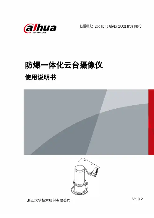
防爆一体化云台摄像仪使用说明书V1.0.2浙江大华技术股份有限公司防爆标志:Ex d IIC T6 Gb/Ex tD A21 IP68 T80℃前言概述本文档详细描述了防爆一体化云台摄像仪的产品概述、安装、连接、使用等内容。
符号约定在本文档中可能出现下列标识,代表的含义如下。
标识说明表示有中度或低度潜在危险,如果不能避免,可能导致人员轻微或中等伤害。
表示有潜在风险,如果忽视这些文本,可能导致设备损坏、数据丢失、设备性能降低或不可预知的结果。
表示是正文的附加信息,是对正文的强调和补充。
修订记录版本号修订内容发布日期V1.0.2 删除敏感词汇。
2020.11V1.0.1 更新模板。
更新公司。
2020.09V1.0.0 首次发布。
-装箱清单开箱之后请仔细核对包装箱内设备及配件,如有异样及缺失,请及时与当地供应商或公司客服部(400-672-8166)联系,产品实时更新,如有更改,恕不另行通知。
如有任何疑问或争议,请以公司最终解释为准。
序号名称数量备注1 防爆一体化云台摄像仪 1 -2 遮阳罩 1 -3 使用说明书 1 -4 产品合格证 1 -5 M10×45内六角圆柱头螺钉、平垫、弹垫、螺母5套用于安装一体化摄像仪6 M3、M10内六角扳手各1 安装产品、调试雨刷用7 防爆挠性管 1 1米使用安全须知感谢您选用本公司的防爆产品!安装、使用前请仔细阅读本手册,遵守警告事项,并妥善保存好本手册。
质量保证对于本公司生产的防爆一体化云台摄像仪在产品保修期内,本公司提供免费维修服务,但如有以下情形者,将酌情收取材料成本工时费用:●不按照使用说明书中的规定进行操作导致损坏。
●擅自拆机导致损坏。
●雷击及不可抗拒的自然灾害。
若公司与用户之间另有书面服务承诺或规定,将严格按照承诺或规定的要求进行处理。
安全保证该设备的运行符合以下两个条件:●设备的运行不会产生有害的干扰。
●设备的运行在一定程度上不受外部干扰,甚至是不良干扰的影响。
Dahua HD IR Bullet Network Camera Quick Start GuideDahua HD IR Bullet Network CameraQuick Start GuideVersion 1.0.0ZHEJIANG DAHUA VISION TECHNOLOGY CO., LTD.WelcomeThank you for purchasing our network cameras.This user’s manual is designed to be a reference tool for using your product.Please read the following safeguards and warnings carefully before you use this series product. Please keep this user’s manual well for future reference.Important Safeguards and WarningsElectrical safety●All installation and operation should conform to your local electrical safety codes.●The power source shall conform to the requirement of the Safety Extra Low Voltage (SELV)standard, and supply power with rated voltage which conforms to Limited power Sourcerequirement according IEC60950-1. Please note that the power supply requirement is subject to the device label.●Make sure the power supply is correct before operating the device.● A readily accessible disconnect device shall be incorporated in the building installation wiring●Prevent the power cable from being trampled or pressed, especially the plug, power socket and thejunction extruded from the device.●We assume no liability or responsibility for all the fires or electrical shock caused by improperhandling or installation.Environment●Do not aim the device at strong light to focus, such as lamp light and sun light, otherwise it mightcause over brightness or light marks, which are not the device malfunction, and affect the longevity of Charge Coupled Device (CCD) or Complementary Metal-Oxide Semiconductor (CMOS).●Do not place the device in a damp or dusty environment, extremely hot or cold temperatures, or thelocations with strong electromagnetic radiation or unstable lighting.●Keep the camera away from water or other liquid to avoid damages to the internal components.●Keep the indoor device away from rain or damp to avoid fire or lightning.●Keep sound ventilation to avoid heat accumulation.●Transport, use and store the device within the range of allowed humidity and temperature.●Heavy stress, violent vibration or water splash are not allowed during transportation, storage andinstallation.●Pack the device with standard factory packaging or the equivalent material when transporting thedevice.●The device needs to be installed in the location where professional staff can cover (professionalsneed to know the attentions of using the device), non-professionals are not allowed to enter device installation area when the device is operating normally, which may cause accidental damage.Operation and Daily Maintenance●Do not directly touch the heat dissipation component of the device to avoid scald.●Do not dismantle the device because there is no component that can be fixed by users themselves.Otherwise, it might cause water leakage or bad image due to unprofessional dismantling.●Please contact after-sale service to replace desiccant when it becomes green. (The desiccant isnot provided by default)●It is recommended to use the device together with lightning arrester to improve lightning protectioneffect.●It is recommended to get the grounding holes to be grounded to enhance the reliability of thedevice.●Do not directly touch the optic component CCD or CMOS. You can use the air blower to blow awaythe dust or dirt on the lens surface. Please use a dry cloth wetted by alcohol to wipe away the dust gently if necessary.●Use the dry soft cloth to clean the device. If the dust is difficult to be removed, please wipe it awaywith a clean cloth wetted slightly by the mild detergent, and then use the dry cloth to clean the device. Do not use volatile solvents like alcohol, benzene, thinner, or strong detergent withabrasiveness, otherwise it will damage the surface coating or reduce the working performance of the device.●When installing or using the device, do not directly touch or wipe the surface of the dome coverbecause it is an optical device. If stained with dirt, use oil-free soft brush or air blower to gently wipe it away. If stained with grease or fingerprint, use soft cloth to gently wipe the water drop or oil and wait till it is dry, and then use oil-free cotton cloth or lens cleaning paper soaked with alcohol or detergent to wipe from the lens center outward till it is clean.●We are not liable for any problems caused by unauthorized modification or attempted repair.●The dome cover is a kind of optical component, please do not touch or wipe the cover surfaceduring installation and application, it may stain dust, grease or fingerprint, you can use absorbent cotton to dip some diethyl ether or use soft cloth to dip some water and then wipe gently. You can also use air gun to remove the dust if the cover is stained with dust.Warnings●Please strengthen the protection of network, device data and personal information, adoptnecessary measures of guarantee device network security, including but not limited to using strong password, modifying password regularly, upgrading firmware to the latest version, isolatingcomputer network and so on. For the IP camera firmware of some old version, the ONVIFpassword won’t b e modified automatically after the main password of the system is modified. You need to upgrade the camera firmware or upgrade the ONVIF password manually.●Please modify the default password after login to avoid being stolen.●Use the standard components provided by manufacturer and make sure the device is installed andfixed by professional engineers.●The surface of the image sensor should not be exposed to laser beam radiation in an environmentwhere a laser beam device is used.●Do not provide two or more power supply sources for the device; otherwise it might damage thedevice.Disclaimer●This manual is for reference only. Please refer to the actual product for more details.●Minor differences might be found in user interface, and there might be deviation between the actualvalue of some data and the value provided in the manual due to the reasons such as the realenvironment is not stable. Please refer to the final explanation of the company if there is any doubt or dispute.●All the designs and software are subject to change without prior written notice. The manual will beregularly updated according to the product upgrade without prior announcement.●Please contact the supplier or customer service if there is any problem occurred when using thedevice.●Please contact the customer service for the latest procedure and supplementary documentation.●Please visit our website or contact your local service engineer for more information.●The company is not liable for any loss caused by the operation that does not comply with themanual.●If there is any uncertainty or controversy, please refer to our final explanation.Regulatory InformationFCC Information1.1 FCC conditions:This device complies with part 15 of the FCC Rules. Operation is subject to the following two conditions: ●This device may not cause harmful interference●This device must accept any interference received, including interference that may causeundesired operation.1.2 FCC compliance:This equipment has been tested and found to comply with the limits for a digital device, pursuant to part 15 of the FCC Rules. These limits are designed to provide reasonable protection against harmful interference. This equipment generate, uses and can radiate radio frequency energy and, if not installed and used in accordance with the instruction manual, may cause harmful interference to radio communication. However, there is no guarantee that interference will not occur in a particular installation. If this equipment does cause harmful interference to radio or television reception, which can be determined by turning the equipment off and on, the user is encouraged to try to correct the interference by one or more of the following measures:●Reorient or relocate the receiving antenna.●Increase the separation between the equipment and receiver.●Connect the equipment into an outlet on a circuit different from that to which the receiver isconnected.●Consult the dealer or an experienced radio/TV technician for help.Note●Please refer to the disk for more details, check and download the corresponding user’s manual andtool.●Before installation, please open the package and check all the components are included.●Contact your local retailer as soon as possible if something is broken in your package.Table of Contents1 Device Framework (6)1.1 Device External Cable (6)1.2 Dimension (7)2 Device Installation (8)2.1 Install SD Card (8)2.2 Fix Device (9)2.3 Connect Device Cable (9)2.4 Adjust Device Angle (12)3 Network Configuration (13)3.1 Device Initialization (13)3.2 Modify IP Address (14)3.3 Login WEB Interface (15)1 Device Framework1.1 Device External CableNote●The following structure figure is for reference only. It is only used to know thefunctions of cable ports.●There might be some minor differences between different devices, so please referto the actual products you purchased.Figure 1-1Please refer to Table 1-1 and Table 1-2 for the functions of external cable and I/O portTable 1-11.2 DimensionNoteThe following figure is for reference only, which is only used to know the devicedimension.Refer to 错误!未找到引用源。
高速球摄像机安装步骤在选择好高速球后,并不代表其工作已经完成了,还有一个重要的步骤就是安装和调试高速球,其调试和安装非常的重要,如果调试和安装这两个步骤没有做好,就会影响到高速球的工作性能和效果,所以在调试和安装的过程中我们一定要注意,下面教大家怎么来安装和调试高速球。
高速球安装需要的工具电源和电源稳定,并且符合高速球机说明书上的要求的电源一个。
把电源线、网线、、视频线和控制线数根,一定要跟高速球机的接线端口配套的线,最好是产品的出厂原装线。
已经选好的高速球机一台,质量一定要好,而且要符合自己的要求,不然测试的时候会误认为是产品质量出问题了。
高速球安装步骤安装时要求把高速球机跟电源连接起来。
接地线路也要安装好,防止电路被烧坏,可以保护到电路。
2.按照要求把高速球机安装在平稳的地方,周围的环境要稳定,不能有震动,不然画面会出现抖动或者是不清晰,影响实际的视觉效果。
水汽比较重的地方也要避开,以免让高速球机受潮,损坏内部元件。
还要注意的一点就是周围不能有物体遮挡镜头,以免影响高速球机工作。
3.按照下面的电路图把整个系统接好,在接高速球机跟电脑的连接线路的时候注意接口的线一定要插紧,不然一段时间后线路会出现短路和断路的情况。
到这一步高速球机的安装就完成了。
4.最后在控制端设置好各种参数,包括画面的色彩度,亮度和色彩平衡度等各种参数,直到画面效果满意为止。
最后调试工作也完成了。
版权申明本文部分内容,包括文字、图片、以及设计等在网上搜集整理。
版权为潘宏亮个人所有This article includes some parts, including text, pictures, and design. Copyright is Pan Hongliang's personal ownership.用户可将本文的内容或服务用于个人学习、研究或欣赏,以及其他非商业性或非盈利性用途,但同时应遵守著作权法及其他相关法律的规定,不得侵犯本网站及相关权利人的合法权利。
高速球型一体化摄像机安装和使用手册在使用高速球型一体化摄像机之前,敬请您仔细阅读本使用手册安全提示:在正三角形中闪烁的箭头符号,用以提醒用户在本产品中附近出现较大的“非绝缘危险电压”,足以对人体产生危险。
在正三角形中的注意号,用以提醒用户参考有关该机的重要操作与维护的文字说明。
目录一、注意事项 (1)二、功能介绍 (2)三、菜单设置 (3)四、球机设定............................................................... .. (6)1.系统连接 (6)2.球机地址设定 (7)3.协议和默认波特率设定 (7)4.通信波特率设定 (8)5.端接电阻选择 (8)五、系统安装 (8)六、技术参数 (15)七、简易故障排除 (16)八、附录Ⅰ 防雷击、浪涌 (17)Ⅱ 透明罩的清洁......... (17)Ⅲ RS485总线常识...................................... .. (18)Ⅳ AC24V线径和传输距离的关系 (19)Ⅴ 国内外线规对应表 (20)一、 注意事项1.在安装使用全方位智能化高速球型摄像机机之前,请首先仔细阅读本说明书。
2.球机使用电源:AC24V。
球机输入额定电压会在球机底座或相应的地方标明。
3.球机内部为精密光学及电子器件,在运输保管及安装过程中要防止重压、剧烈震动等不正确的操作方法,否则可能对产品造成损坏。
4.请不要自行拆卸球机内部器件,以免影响使用,里面没有用户自行维修的零件。
5.使用中必须遵守各项电气安全标准,配用本机自带的专用电源。
RS-485及视频信号在传输过程中应与高压设备或电缆保持足够的距离,必要时还要做好防雷击、防浪涌等防护措施。
6.不要直接将高速球置于室外使用,避免球机淋雨、受潮等。
在潮湿的地方请不要使用。
如果安装在室外,则必须使用密封防护罩,绝对禁止露天单独使用。
7.不要在超出限定的温度、湿度或电源规格的状态下使用本产品。
(物联网)智能高速球型摄像机使用手册V—序言—本说明书是智能高速球型摄像机用户的基本说明书。
本说明书由重要的安全和警告信息、智能高速球型摄像机产品的功能说明、性能特点及参数、安装步骤、壹般故障及解决方法、维护等使用智能高速球型摄像机时必须了解的内容组成。
首次使用智能高速球型摄像机的用户及以前使用过类似产品的用户于使用本机前最好先阅读壹遍本说明书。
如可能,请最好从第1页开始按顺序阅读。
如用户希望只见需要的部分,也可参考目录加以选择。
目录—重要的安全和警告信息—2—注意事项—3—产品简介—4—性能特点—4—功能说明—5—壹般操作—6—球机设定—7—系统安装—13—球机性能指标—18—壹体化摄像机性能指标—19—常见故障分析—20-维护-21—重要的安全和警告信息—于开始安装和使用之前,请先阅读以下的警告信息:1.应该由经过培训的有资格的服务人员进行安装和维护,且遵守当地的电器安 装规定。
2.室内球机设计制造为室内使用,不能暴露安装于能够淋到雨或非常潮湿的地方。
3.于重新安装或维修后,需测量电路部分和外壳之间的电阻,检查是否绝缘良 好。
应保证电路部分和外壳不短路。
4.于安装中用于支撑重量的材料,应能承受四倍于球机的重量。
产品和手册中有下列标记:—注意事项— 1. 于安装使用全方位智能化高速球型摄像机机之前,请首先仔细阅读本说明书。
2. 球机使用电源:DC12V 。
球机输入额定电压会于球机底座或相应的地方标明。
3. 球机内部为精密光学及电子器件,于运输保管及安装过程中要防止重压、剧烈震动等不正确的操作方法,否则可能对产品造成损坏。
4. 请不要自行拆卸球机内部器件,以免影响使用,里面没有用户自行维修的零件。
5. 使用中必须遵守各项电气安全标准,配用本机自带的专用电源。
RS-485及视频信号于传输过程中应和高压设备或电缆保持足够的距离,必要时仍要做好防雷击、防浪涌等防护措施。
6. 不要直接将高速球置于室外使用,避免球机淋雨、受潮等。
高速球形一体化摄像机用户手册目录第一章产品概述 (5)第二章安全及注意事项 (6)第三章技术参数 (7)3.1电器规格 (7)3.2工作环境 (7)3.3机械运动技术参数 (7)3.4控制通讯方式 (8)3.5外型尺寸 (9)第四章球机的设置安装及连接 (10)4.1球机的设置 (10)4.1.1球机开关位址设置 (11)4.1.2球机通讯协议设置 (11)4.1.3球机通讯速率(标准)设置 (12)4.2球机的安装 (13)4.2.1壁架支架式安装 (13)4.2.2嵌顶式安装 (16)4.3球机的连接 (17)4.3.1球机内部的连接 (17)4.3.2球机外部的连接 (18)4.3.2.1带报警功能球机的连接 (18)4.3.2.2不带报警功能球机连接 (19)4.3.2.3球机485通讯线的连接 (19)4.4球机的试机 (20)第五章主要功能介绍 (21)5.1名词解释 (21)5.2操作功能 (21)5.3机械及安装功能 (22)5.4内置数码摄像机 (22)5.5其他功能 (23)5.6监视器屏幕提示符介绍 (25)第六章OS D菜单设置 (26)6.1O S D菜单结构 (26)6.2O S D菜单设置操作 (27)6.2.1用F O RE A D Y或V TC协议操作 (27)6.2.2用P E LC O协议操作 (27)6.3设置操作 (28)6.3.1系统设置 (28)6.3.1.1语言设置 (28)6.3.1.2显示开关位址 (28)6.3.1.3操控位址(控制位址)设置 (28)6.3.1.4防区位址设置 (28)6.3.1.5其它设置 (28)6.3.1.5.1日期设置 (28)6.3.1.5.2星期设置 (28)6.3.1.5.3时间设置 (28)6.3.1.5.4显示位置设置 (28)6.3.1.5.5显示方式设置 (29)6.3.1.5.6运行提示设置 (29)6.3.1.5.7时间排程设置 (29)6.3.2影像设置 (29)6.3.2.1曝光设置 (29)6.3.2.2效果设置 (29)6.3.2.3镜头功能设置 (29)6.3.2.4影像补偿设置 (29)6.3.2.5遮蔽设置 (29)6.3.2.6图像设置保存 (29)6.3.3报警设置 (29)6.3.3.1报警位址设置 (29)6.3.3.2状态设置(报警工作状态) (30)6.3.3.3布防方式设置 (30)6.3.3.4定时布防设置 (30)6.3.3.5报警联动设置 (30)6.3.3.6视频异动报警的工作模式设置 (30)6.3.3.7视频异动报警的联动设置 (32)6.3.3.8查询报警记录 (32)6.3.4运行设置 (32)6.3.4.1预置位设置 (32)6.3.4.2巡视组设置 (32)6.3.4.3扫描设置 (32)6.3.4.4模式设置 (33)6.3.4.5守望位设置 (33)6.3.4.6自动追踪设置 (33)6.3.5系统测试 (34)6.3.5.1启用坐标设置 (34)6.3.5.2停用坐标设置 (34)6.3.5.3系统测试 (34)6.3.5.4控制限速 (34)6.3.5.5镜头限速 (34)6.3.6出厂设置 (34)6.3.6.1恢复出厂设置 (34)6.3.6.2恢复开关位址 (34)第七章故障及排除方法 (35)第八章保养及服务 (36)第九章声明 (37)第一章产品概述高速球形一体化摄像机(简称球机,高速球)是集一体化摄像机与万向变速云台于一体的高科技监控产品,可任意迅速定位及连续追踪扫描,实现全方位,无死角的监视,可以自动适应环境明暗和焦距远近的变化,被广泛用于机场码头、银行金库、场馆会所、治安防范,军事禁区等场所的24小时全天候监控。
如何安装球形摄像机如何安装球形摄像机导语:随着球形摄像机的普及,在街道、路口、地铁、校园等地随处可见,但是呢,随着而来的问题也不容我们忽视。
就比如球型摄像机安装遇到的问题也增多,为大家提供常见球形摄像机故障排除法。
那么,今天我们就一起来了解如何安装球形摄像机的相关步骤内容吧。
如何安装球形摄像机安装球型摄像机步骤:1.先拨地址码。
按照二进制的规则算好需要安装摄像机的地址码,然后将护照拆下来,将地址码拨好,组装复原。
2。
固定球机支架,安装前,先要想好需要监控的方位和角度,选好安装位置,固定支架。
3,布线,将电源线、视频线、控制线依次布到摄像机处。
要求能从摄像机支架内穿出富裕15CM左右。
4,测试电源线电压,看是否与摄像机电压吻合,这部很重要,否则将烧毁摄像机。
5,安装摄像机,将摄像机线插入摄像机支架内,固定摄像机螺丝。
6,接线,将电源线、视频线(做好BNC接头或者水晶头),控制线分别按照一定顺序接好。
将光端机/录像机处的控制线,也按照相同接线顺序接好线。
视频线接入录像机。
7,测试摄像机,看有无图像,操作控制摄像机上下左右转动。
8,故障排除,无图像,先看摄像机是否有电,其次检查BNC/水晶头是否接触良好。
摄像机无法控制移动,检查控制线接触是否良好,之后检查控制线接线顺序是否一致。
内容推荐:注意事项一:接地球机的接地主要分为外壳接地和内部电气接地。
外壳接地主要用来防止静电积累、电气漏电等,室外球机还特别要加装外部防雷措施。
注意事项二:供电为保证球机正常工作,供电电源不宜低于球机输入电压的标称值。
当标称值为24VAC,电压波动不宜超出±25%。
当市电电压波动超出+5%~-10%范围时,应设交流稳压装置。
可安装UPS以提供不间断稳定电源供给。
注意事项三:地环回路即使设备有效接地,但球机和中心设备间不同地位的零电势存在差异、电源负载存在不均衡,仍会引起接地电位差,从而影响视频信号的'正常传输,通常表现为图像中间有水平方向的杂波。
高速球安装说明书高速球安装说明书监控周边设备知识2007-08-22 11:53:31 阅读1106 评论0 字号:大中小目录重要安全措施 (2)注意事项 (3)球机结构 (4)吊装支架尺寸 (5)墙装支架尺寸 (6)室内球安装示意图 (7)室外球安装示意图 (8)球机地址码设置 (9)像机拨码设置 (10)球机协议码设置 (11)操作方法 (12)球机协议码功能 (13)像机操作说明 (18)常见故障排除 (20)规格参数 (21)重要安全措施1.安装本机之前,请仔细阅读说明书。
2.应遵守设备上和说明书上的所有警告事项。
3.应遵守全部指示操作和使用说明书。
4.要使用经销商推荐的配件,否则导致故障,我公司概不负责。
5.本机应使用电源线上标明的电源种类和电压,如安装地点的电源和电压不明确,请与经销商联系。
6.请不要擅自拆卸本机,有关维修事宜请与销售商联系。
7.应避免受撞或振动。
摄像机若使用或存放不当,将受损害。
8.清洗球机机体时,请不要使用强烈的或带有研磨性的清洁剂。
球机机体有污垢时,请用干的软布擦拭。
如果污垢较严重时,请用中性清洁剂轻轻擦试。
擦拭时,请小心不要划伤圆形保护盖。
然后用干布擦去清洁剂的残留部分。
9.如遇下列情况请与销售商联系:a、电源、控制线损害b、掉落或机壳受损c、设备性能出现异常d、按说明书操作后仍未正常工作10.更换零件时,请用销售商提供的或原部件性能相同的零件,未经认可的代用品会导致危险并损坏设备。
注意事项1.不要让室内机淋雨或在潮湿的地方使用。
2.不要以摄像机瞄准太阳。
不要使摄像机长时间瞄准光亮物体,无论摄像机在使用中或非使用中。
否则,可能造成图像模糊或产生光晕。
3.绝对不要将摄像机长时间对着强光或暴露在光源下的地方。
如果射灯等点光源在显示屏幕上形成光斑,部分图像会因为在摄像机改变面部等情况下CCD的滤色镜工作恶化而褪色。
4.不可将本机颠倒安装。
本机是为安装在天花板或墙壁上而设计的。