施耐德电气KNXEIB智能灯光控制系统介绍
- 格式:ppt
- 大小:14.09 MB
- 文档页数:58
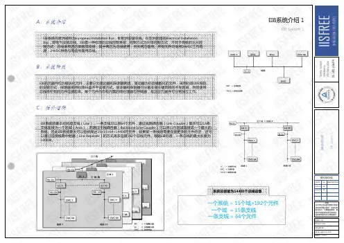
KNX/EIB智能建筑控制系统方案一、电气KNX/EIB智能建筑控制系统介绍随着人们对建筑品味的日益提高,人们在希望降低能源消耗的同时,对建筑物电气安装的灵活性、舒适性与功能性也提出了越来越高的要求,它有力的推进了建筑系统工程的发展。
建筑系统工程的基础是建筑安装技术的一体化,打破行业的界线,将智能化的家庭技术与楼宇技术的全部功能包揽于一身。
传统的电气安装技术已难以满足现代化建筑的需要,所谓智能化的建筑成为当今先进建筑的必然。
早在20世纪80年代中期,各家公司就已不谋而合的酝酿着将总线技术应用于电气安装技术与楼宇技术,人们已经发现各个厂家专用系统的进入市场,给市场的相互广泛渗透设置了屏障。
在此背景下,发源于欧洲的KNX/EIB(European Installation Bus,欧洲安装总线)智能安装系统应运而生。
KNX/EIB是将目前计算机控制技术领域最新的现场总线技术应用于传统的电气安装领域的新技术,它使来自各行各业各工种的各个单独的产品和系统联合成为一个相互联通的系统,有效地实现了对照明、调光、百叶窗、场景控制、用电负荷控制、安保、供热系统等的智能控制,达到安全、节能、人性化的效果,并能在今后的使用中方便地根据用户的需求进行变更,成为真正灵活智能的电气安装系统。
它的优势是传统电气安装所无法比拟的。
1. KNX/EIB 面向未来的电气安装系统现代的建筑离开电是无法想象的。
无论是传统的照明和插座,还是现代化的通讯、安保等技术,都离不开电的供应。
KNX/EIB技术本身是在传统电气安装技术基础上引入现场总线概念而发展起来的,它对传统电气安装技术而言是一次突破性的革命,是当今建筑技术领域非常优秀的技术标准。
KNX/EIB总线系统适用于工业建筑、楼宇建筑和住宅建筑。
工程设计简单和使用过程中的灵活性与经济性,已经使KNX/EIB获得了日益广泛的应用,它克服了传统安装技术的诸如控制电缆的数量的不断增多、工程设计耗时费力、火灾负担高以及维修与故障查找的能见性差等许多缺点,综合了过去必须使用许多单个系统才能完成的建筑功能,它具有现场总线技术的核心优点如系统结构简单,设计、安装和维护方便,全分散控制等,解决了建筑中由于涉及工种和功能过多而导致系统过于独立和操作复杂的问题,电力线可直接通向用电设备,传感器可方便的用总线电线来连接,相同的界面、相同的按钮、跨行业的一体化控制,应用领域空前扩展。

施耐德莫顿 INSTA BUS EIB智能楼宇控制系统方案施耐德莫顿 INSTA BUS EIB智能楼宇控制系统目录●设计简要●前言一、施耐德 I-BUS 总线控制系统特点及优势二、工程设计三、工程验收及竣工资料四、系统培训及维护设计简要1.品牌选择选用世界最先进的施耐德莫顿EIB/KNX INSTA BUS系统。
遵循欧洲电气安装总线EIB标准,系统具有高可靠性、灵活性、舒适性、安全性、经济性,强扩展能力,强兼容性和开放性。
2.功能实现采用智能面板和智能驱动模块,可定时开闭、调光,光线感应控制。
可统一管理,遥控开启等。
3.集成功能系统采用EIB网关,I- bus系统可接受其他系统干结点信号、交直流信号,实现消防系统、安保系统、音响系统、会议系统的联动,使灯光或设备及时联动。
4.施工EIB I-bus总线是带屏蔽的四芯控制线,可与共同电源线缆敷设,在强电系统中统一考虑,方便、节省。
前言现代化的建筑对于配套设施的需求越来越多样化,既要满足多功能的要求,又要易于操作,同时还要具有高度经济性,灵活性及安全性。
从而对楼宇的智能控制系统提出了更高的要求,越来越多的现代楼宇采用了智能灯光照明控制系统,从而达到了经济合理使用能源的目的,增强了自动化管理的程度,实现了绿色照明,楼宇自控、负荷控制,中央空调、供热系统,门禁、报警系统,无线巡更系统等应用的高度集成,构建起现代化建筑的自动化体系,用最好的性能价格比来迎接智能建筑时代的到来。
施耐德电气(中国)投资有限公司,简称施耐德公司,是一家专业大型电气公司,其EIB/KNX INSTA BUS智能安装系统已在各种建筑领域成熟使用近20年,自2001年进入中国市场以来,在上海F1国际赛车场、上海HYTTA REBENCY HOTEL、上海盛大金磐、北京新源大厦、滨海会展中心等大型项目中已得到使用。
由于施耐德INSTA BUS EIB控制系统的高度集成性和扩展性,向诸多系统提供了标准的物理接口,使该系统使用功能更为强大。

目录1智能照明控制系统 (2)1.1系统概述 (2)1.2需求分析 (2)1.3设计原则 (2)1.4设计要点 (3)1.5系统设计 (4)1.5.1KNX总线拓朴结构 (4)1.5.2系统结构 (5)1.5.3系统功能 (6)1.6方案设计 (6)1.6.1剧院大厅 (6)1.6.2展示区域 (7)1.6.3剧院观众席 (7)1.6.4公共区域 (8)1.6.5后台休息区 (9)1.6.6泛光照明 (9)1.6.7地下车库照明 (9)1.7与第三方接口 (10)1.8主要设备参数 (10)1.8.1监控管理软件 (10)1.8.22、4、8、12路16A开关控制器 (11)1.8.3窗帘控制模块 (12)1.8.4触摸屏 (12)1.8.5存在感应器带耦合器光感红外 (12)1.8.64路通用输入/输出接口 (13)1.8.7带LCD温控智能控制面板 (13)1.8.8智能面板带耦合器 (14)1.9施耐德电气介绍(仅供参考) (14)1.9.1施耐德电气集团简介 (14)1.9.2施耐德电气ISC ECS (16)1智能照明控制系统1.1系统概述珠海歌剧院设计一套智能灯光控制系统,采用Schneider KNX全数字分布式控制系统,对区域内各类照明等电气设备进行自动化和集中控制管理,实现能源监测,不仅可有效管理楼宇的电气设备,提供灵活多变的使用功能和效果,还可以维护并延长灯具及电气设备的使用寿命,达到安全、节能、人性化、智能化的效果,并能在今后的使用中方便地根据用户的需求进行扩展。
1.2需求分析根据歌剧院设计规划和使用要求,配置智能照明控制系统的功能分析如下:1.3设计原则根据现行国家规范和项目技术文件的要求,我们在对珠海歌剧院项目KNX 智能照明控制系统的设计中遵循以下的原则:先进性:采用代表当今世界先进技术水平的成熟稳定的系统设备,并建立一个可扩展的平台,充分保护前期工程投资和后续扩展,使系统具有先进性。

智能照明系统一、概述现代化建筑对照明的要求越来越高,不仅要求提供舒适、绿色的光照,同时不同的场合需要不同的照明环境。
传统的照明控制一般采用开关手动控制,对于上述要求很难实现,而且线路十分复杂,操作非常繁琐。
随着用户要求的提高和技术的进步,传统的照明控制由于许多问题无法解决而逐步被智能照明控制取代,这已成为一种趋势。
宁波电力调度大楼是一座现代化办公楼,本次智能照明设计采用施耐德公司的莫顿智能化照明控制系统,对大楼的不同区域、不同使用功能的照明营造有层次、变化的灯光环境、美化办公及生活环境;减少人力工作疏忽,节约能源和人力资源;降低人力工作强度,增强控制的灵活性和可靠性。
二、设计依据•招标文件技术要求•《民用电气设计规范》JGJ/T16-92•《建筑电气安装工程质量检验评定标准》GYJ1253-88•《民用建筑照明标准规范》GBJ133-90•《智能建筑评估标准》DG/TJ08-602-2001J10105-2001三、设计目的通过智能化照明控制系统,给大楼各功能区域以焕然一新的风格,完成公共区域灯光回路的开关控制,完成整个大楼照明的自动化控制。
智能化照明控制技术是计算机技术、通讯技术、控制技术相结合、相渗透的产物,是现代高新技术的结晶。
与以往的照明控制相比,它从人工控制、单机控制过渡到整体性控制,从普通开关过渡到智能化开关,其最突出的特点是能够预置场景的变化,不同的照明回路强度组合形成不同的“场景”,场景可预置并存储在控制器里,调用时只需按一键就能选择场景和通过预设的程序自动变换场景(可按时顺序、时间、事件等),操作十分方便。
可依据需要实现自动时间控制、自动顺序控制、占空(动静)探测控制、事件程序响应控制、分割空间控制等多种方式的自动控制,也可增加自动日照控制、事件程序响应控制、远程电话控制、远程Internet控制等。
采用莫顿智能照明控制系统完成车库区域、公共走廊、电梯厅、卫生间等公共区域的灯光的控制。

Product and Applications DescriptionThe Switch-/Dimming Actuator is a KNX device for control-ling up to two groups (channels) of lamps via theDC 0/1 -10 V control terminal of dimmable electronic ballasts(ECGs). In addition there is per channel a switching contactfor direct switching on/off of the connected lamps.The device is installed into or attached to a 4 x 4 inch junc-tion box. The bus is connected via a bus terminal block. Theactuator electronics are supplied via the bus voltage.Each channel of the Switch-/Dimming Actuator can controlseveral dimmable electronic ballasts. Their number is limitedby the switching capacity and by the control power. If theon/off function is not used via the switching contact of theSwitch-/Dimming Actuator, the number of controllable ECGsis only dependent on the load of the DC 1-10 V control volt-age. This might allow controlling a larger number of ECGs(see Technical Specifications below).Various functions can be configured per channel such as forswitching on/off lamps, dimming up / down or setting a par-ticular dimming level.With the ETS (Engineering Tool Software) the applicationprogram is selected, its parameters and addresses are as-signed appropriately and downloaded into theSwitch/Dimming Actuator.Amongst others, the application program includes an op-tional counter for switching cycles and operating hours withthreshold monitoring for each output and an integrated 8-bitscene control for incorporating the output into up to 8scenes.Each output of the actuator may be set to one of the follow-ing operating modes:- Normal operation- Timer operationBuilding sitThe buildinswitching thswitches anbeen commApplicatiThe device n“07 B0 A2ExampleP.T.O.ng site functionuilding site function provided ex-factory enablesing the building site lighting on and off via bus walles and actuators, even if these devices have not yetommissioned with ETS.lication Programvice needs the application program2 Dimmer 983C01”.mple of OperationL1V30425157A - DS02instabus ®Technical ManualSwitch-/Dimming Actuator JB526C235WG1 526-4CB23April 2017 / Page 2Location and Function of the Interface ElementsA4A5A6A7A1A2A7A3A3A7A8A9A10A11A13A12A1Type label (with space for physical address of the ac-tuator)A2Identification number of the device A3Protective lid over bus connectionA4Bus connection terminal block for single core conduc-tors with 0.6...0.8 mm ØA5LED for indicating normal operating mode (LED off) or addressing mode (LED on); returns to normal operating mode automatically after receiving the physical address A6Learning button for switching between normal operat-ing mode and addressing mode and for receiving the physical address A71/2 inch screw nut A8Wire (red) Load A (AWG #12)A9Wire (black) Line (Hot)(AWG #12)A10Wire (yellow) Load B (AWG #12)A11Wire (grey) DIM Common (AWG #18)A12Wire (purple) DIM A (AWG #18)A13Wire (blue) DIM B (AWG #18)Dimension DiagramDimensions in mm (inch)(2.76)(2.76)(3.54)(1.76).B1B4B2B1B3B1B4B2B3B14” x 4” Junction Box B2DeviceB3Bus connection pins of the module for connection of the bus terminal block for single core conductors with 0.6…0.8 mm ØB41/2 inch screw nutMounting and Dismounting∂Mounting of a JB module:Option 1 (mounting inside a J-Box)- Insert the thread of the JB module (B2) into the 1/2 inch knockout between two adjacent J-Boxes (B1)- Fasten the JB module (B2) with the 1/2 inch thread nut (B4)- Remove the protective lid (B3) and connect the bus wire to the bus terminal block (A4)- Connect the wires from the device to the field wires using wire nuts (not provided in package)Option 2 (mounting outside of a J-Box)- Insert the thread of the JB module (B2) into the 1/2 inch knockout of the J-Box (B1)- Fasten the JB module (B2) with the 1/2 inch thread nut (B4)to the J-Box (B1)- Connect the bus wire to the bus terminal block under the protective cover (B3)- Connect the wires from the device to the field wires using wire nuts (not provided in package)∂Assignment of the Physical Address:- A short push (< 2 s) of learning button (A6) enables the ad-dressing mode, which is indicated when the LED is continu-ously on (A5). The device returns to normal operating mode (LED Off) automatically after receiving the physical address or if the learning button is pushed again.- A very long push (> 20 s) of the learning button resets the device to factory settings. This is indicated by constant flash-ing for 8 seconds.- A long push (> 5 s up to 20 s) of the learning button ena-bles the Connection Test for commissioning with Desigo.This mode can be disabled by a short push any time.- Install the protective lid (B3) and fasten with screws (pro-vided in package)∂Dismounting a JB module:- Disconnect power to the module- Remove the wire nuts and bus connection- Unfasten the 1/2 inch thread nut (B4) connecting the JB module (B2) to the J-Box (B1)- Remove the JB module (B2) from the J-Box (B1)D2.4WiringBus connectionSlipping off/on bus connection blocksThe bus connection block consists of two components (C2.1and C2.2) with four terminal contacts each. Take care not to damage the two test sockets (C2.3) by accidentally connect-ing them to the bus cable or with the screw driver (e.g.when attempting to unplug the bus connection block).Slipping off bus connection blocks- Carefully put the screw driver to the wire insertion slit of the bus connection block’s grey component (C2.2)and- pull the bus connection block (C2) from the module.NoteDon’t try to remove the bus connection block from the bot-tom side. There is a risk of shorting-out the device!Slipping on bus connection blocks- Slip the bus connection block (C2) onto the guide slot of the module and- press the bus connection block (C2) down to the stop.Connecting and Disconnecting bus cables Connecting bus cables- The bus connection block (D2) can be used with single core conductors Ø 0.6…0.8 mm.- Remove approx. 5 mm of insulation from the conductor (D1) and plug it into the bus connection block (D2)(red = +, grey = -)Disconnecting bus cables- Unplug the bus connection block (D2) and remove the bus cable conductor (D1) while simultaneously wiggling it.Connecting mains and load circuit:Connect wires-Connect wire leads using wire nuts.。
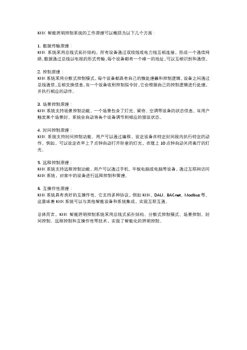
KNX 智能照明控制系统的工作原理可以概括为以下几个方面:
1. 数据传输原理:
KNX系统采用总线式拓扑结构,所有设备通过双绞线或电力线互相连接,形成一个通信网络。
数据通过总线以电报的形式传输,每个设备都有一个唯一的地址,可以互相识别和通信。
2. 控制原理:
KNX系统采用分散式控制模式,每个设备都具有自己的微处理器和控制逻辑。
设备之间通过总线通信,互相交换信息。
当一个设备收到控制指令时,它会根据自己的控制逻辑进行处理,并执行相应的动作。
3. 场景控制原理:
KNX系统支持场景控制功能。
一个场景包含了灯光、窗帘、空调等设备的状态信息。
当用户触发某个场景时,系统会自动将各个设备调节到相应的预设状态。
4. 时间控制原理:
KNX系统支持时间控制功能。
用户可以通过编程,设定设备在特定时间段内执行特定的动作。
例如,可以设定在早上7点钟自动打开卧室的灯光,在晚上10点钟自动关闭客厅的灯光。
5. 远程控制原理:
KNX系统支持远程控制功能。
用户可以通过手机、平板电脑或电脑等设备,通过互联网访问KNX系统,对家中的设备进行远程控制和管理。
6. 互操作性原理:
KNX系统具有良好的互操作性。
它支持多种协议,例如KNX、DALI、BACnet、Modbus等。
这意味着KNX系统可以与其他智能设备和系统集成,实现互联互通。
总体而言,KNX 智能照明控制系统采用总线式拓扑结构、分散式控制模式、场景控制、时间控制、远程控制和互操作性等技术,实现了智能化的照明控制。

智能照明KNX/EIB控制系统应用技术摘要:国家博物馆作为世界级博物馆,不仅在规模上是世界一流的,其内部的控制系统也是世界一流的,因此能体现出国家博物馆的国际地位。本工程中同时配备了西门子的智能照明控制系统及库柏的应急智能照明控制系统,两个系统根据条件或单独控制,或结合控制,充分体现了绿色照明、智能照明、安全照明、美观照明的使用理念。在本工程中对智能照明控制系统做了分析。关键词: 智能照明KNX/EIB控制系统应用技术Abstract: the national museum as a world-class museum, not only in terms of scale is one of the world first-class, its internal control system is the world’s first-class, so can reflect the national museum of its international status. In this project at the same time equipped with Siemens intelligent lighting control system and the emergency of cooper intelligent lighting control system, the two systems according to the condition or individual control, or a combination of control, fully embodies the green lighting, beautiful intelligent lighting, security lighting, lighting the use of the concept. In this project, the intelligent lighting control system is analyzed.Keywords: KNX/EIB intelligent lighting control system application technology1.引言国家博物馆作为世界级博物馆,不仅在规模上是世界一流的,其内部的控制系统也是世界一流的,因此能体现出国家博物馆的国际地位。作为一个如此庞大的公共建筑,内部的功能分区及其复杂,每个区域对照明的要求各不相同,如何有效地满足各个区域的照明需求,根据精装修的外观要求及区域的使用要求,现场选用了高品质照明灯具的同时,还为其配备了完善的控制系统,从而保证了各个区域的灯光要求,细腻、安全、有效地渗入了建筑的每个角落。本工程中同时配备了西门子的智能照明控制系统及库柏的应急智能照明控制系统,两个系统根据条件或单独控制,或结合控制,充分体现了绿色照明、智能照明、安全照明、美观照明的使用理念。在本工程中对智能照明控制系统使用做如下分析:1.智能照明KNX/EIB控制系统应用技术国家博物馆位于北京市中心天安门广场东侧,项目分为老北馆、老南馆、新馆三个部分,该项目主要实现对灯光的智能控制,并且与安防系统、消防系统联动控制,在新馆楼控机房内实现对博物馆的整体照明控制。安防、消防联动采用硬件进行连接。本项目在设计之初即以节能、生态的目标作为标准,建成一座生态节能示范工程。项目实施时选择(KNX/EIB)产品,并将KNX/EIB产品的节能各要素充分发挥,为节能和生态树立了标杆。KNX/EIB智能控制系统在国家博物馆项目中主要用于以下设备的集成式控制。设计在不同的区域采用不同的控制方式达到最佳的节能效果:中央控制则可对整个国家博物馆大楼的灯光进行集中监视和控制,可通过中控电脑对每个区域的灯具实时显示,通过对上下班时间的限制,可有效降低照明在建筑能源的消耗。光线感应控制、定时控制及人体感应控制可分别根据自然光线、上下班时间及工作人员的活动情况对灯光进行自动控制,既节省人工,方便控制,又可有效节能。例如,在公共区域及上下班时间相对弹性的办公区域进行自动控制,可做到:人来,灯开,人离,灯关,避免人员外出或下班后出现长明灯现象;在上下班比较有规律的办公区,采用定时的方式对灯光自动控制,同样可以避免下班后忘记关灯的情况出现。以上方式都可达到节能的效果,但不同区域、不同控制方式所产生的节能效益是不同的,但实际节能方式和节能效果不仅限于此,例如通过光线感应控制灯光,当自然光照度足够时,光线感应可自动将靠窗边的灯光关闭,当自然光线变暗并且室内有人时,光线感应则可以自动将灯光开启。2.博物馆内智能照明系统设计按照国家博物馆大楼建设理念,在弱电系统中的智能控制系统采用具有世界水平的KNX/EIB的智能控制系统,统筹考虑生态建设、资源节约、体现了人与人的和谐、人与自然的和谐、人与经济活动的和谐,提供一套完善的绿色智能控制的解决方案。在该方案中选用KNX/EIB系列产品控制照明设备,把照明设备总体融入到EIB系统中,实现统一的智能控制。采用了系统中的照度控制、感应控制、定时控制、集中控制等四种控制方式进行节能减排和绿色控制,设计中充分挖掘KNX/EIB产品在节能减排方面的功能和性能优势,充分满足控制需求且最大化节能减排的效果,力求尽善尽美。(1)房间内照明控制国家博物馆内的办公室、会议室灯具采用模拟调光方式。设计在该区域引入了调光控制概念,调光控制是指人工照明和自然照明互补,使工作面保持在工作所需的照明程度上。调光控制概念的出现是由于室内空间的纵深不同,自然采光强度出现变化,近窗的区域采光条件好,于是不需要人工照明,而远窗的区域采光条件差,就需要一定的人工照明来补光。KNX/EIB系统有专门针对调光控制概念设计的产品,在以往的应用当中收获了非常不错的效果。国家博物馆内的所有会议室照明,设计均配置了调光控制器,照明灯具根据环境照度和工作面照度调节灯具亮度,达到照度要求(可根据适用单位和人员的要求任意设定)。(2)文物库房照明控制在文物库放置两联智能面板,控制各灯光回路的开关。可以设置成总开总关、分路控制,无论在哪个位置都能方便对文物库进行本地控制,采用门禁卡和智能开关双重控制,即进门刷卡开灯,出门刷卡关灯。当出现安防、火灾报警时,根据需要系统会自动强制开启或关闭部分灯光回路,极大地提高了建筑的安全性。(3)楼梯、走廊等公共区域控制国家博物馆大楼的大堂、走廊、楼梯间等公共区域的照明由设备监控中心统一控制。控制方式包括:日常定时开关控制、特殊节假日时钟控制,分楼层控制、分区域控制、间隔开关控制、照度的控制等,以及各种组合方式,以达到业主的使用要求和先进智能控制系统高集成性和优化性。照明监控软件采用进口的WINSWITCH控制平台,该软件由欧洲某公司专为EIB系统开发研制,具有友善的操作界面,支持全中文汉字输入显示的优势功能(见图13)。3.系统联动控制国家博物馆项目为应对该项目高要求的安全性能,智能照明系统在最大程度上满足了安防系统和消防系统的要求。安防系统在报警情况下要求迅速地进行画面切换和摄像机图像追踪,摄像机图像的清晰度直接受到现场照度的限制。智能照明系统与安防系统的联动轻松解决了这一难题。安防报警后智能照明系统会根据报警情况实时地点亮该区域的灯光,保证了安全性,同时又解决了正在状态下低照度可以节能的问题。消防报警状态下系统会自动点亮该区域的应急照明,保证应急状态的安全性,帮助人员撤离逃生。同时该照明可以接入正常照明状态,这样既保证了消防情况下的安全性要求,同时也满足了正常照明状态下的照明控制要求。在国家博物馆的智能照明监控系统中,配置了OPC-server开放式协议,不需要对软件进行二次开发,就能使整个KNX/EIB控制系统会通过OPC服务与BMS系统进行通讯,方便EIB系统集成到更高层的楼宇管理系统中去,使得EIB系统能够被更高层的控制平台集成监控。楼宇自控系统可直接监控EIB系统,也可通过以太网监控EIB系统。KNX/EIB在智能建筑中的应用充分发挥了智能控制系统在控制和节能方面的优势,通过对照明设备的控制,融合亮度控制、定时控制、集中控制、环境控制等各种智能控制的优势功能,为节能应用提供了高端的控制方式和友谊的节能效果,符合了国家对新建建筑节能要求的政策,也为为绿色生态的建筑目的提供了保证。项目前期的投资在短期内会得到明显的回报,节能的效果有目共睹,而此产品在国家博物馆的应用也是KNX/EIB智能系统在控制和节能领域的典型应用,也节能项目提供了示范与标杆,在目前全球能源紧缺的环境中,节能环保是大家共同追求的目标,建议在节能方面选择KNX/EIB会收到非常有效的效果。参考文献:[1] 梁文欣.酒店中C-Bus智能照明控制系统的应用方案[J]. 职业时空. 2010(05)[2] 朱则刚.智能照明“照亮”未来生活的每个角落[J]. 电子技术. 2007(06)[3] 刘剑,缪兴.开关量智能照明系统在工程中的运用[J]. 光源与照明. 2006(02)[4] 谭伟,王娜,李锋博,赵学风,李世翠.智能照明实验系统的设计与实施[J]. 光源与照明. 2006(03)。
KNX灯控施耐德电气智能照明系统方案KNX(Konnex)是一种基于开放标准的智能家居控制系统,被广泛应用于照明、空调、安全监测等领域。
而施耐德电气是一家全球领先的电气设备和智能解决方案供应商,其主要业务涵盖了电力管理、自动化管理、低压产品以及安防系统等。
结合KNX和施耐德电气的优势,可以实现更灵活、高效、智能的照明控制系统方案。
首先,KNX灯控系统可以实现智能化的照明控制。
通过连接KNX设备和灯具,可以实现灯光的远程控制和定时控制。
用户可以通过智能手机、平板电脑等设备,随时随地控制灯光的开关、亮度和色温等参数。
同时,可以根据预设的时间表,实现自动化的灯光控制,根据天亮天黑的时间自动开关灯光,节省能源的同时提高生活的便利性。
其次,KNX灯控系统可以实现照明场景的定制。
用户可以通过KNX系统,预设不同的照明场景,根据不同的需要,一键切换不同的场景。
例如,用户可以预设一键切换到"会议模式",将所有灯光调暗,提供舒适的会议环境;或者切换到"观影模式",将灯光调至最低亮度,为观影提供更好的观影体验。
通过灵活的场景定制,可以满足用户不同的需求,提升使用体验。
第三,KNX灯控系统可以实现照明设备的联动控制。
通过KNX系统,可以将照明设备与其他智能设备进行联动控制,实现智能化的家居管理。
例如,用户可以设置当人们进入房间时,灯光自动打开;当人们离开房间时,灯光自动关闭,从而实现节能的效果。
此外,还可以将照明设备与窗帘、音乐设备等进行联动控制,实现更加智能的家居体验。
最后,施耐德电气作为一家全球领先的电气设备和智能解决方案供应商,其产品具有高质量和可靠性。
施耐德电气提供了各种灯控产品,包括开关、调光器、传感器等,可以满足不同用户的需求。
同时,施耐德电气还提供了完善的售后服务,保障用户的使用体验。
综上所述,KNX灯控施耐德电气智能照明系统方案可以实现智能化、灵活化、定制化的照明控制。
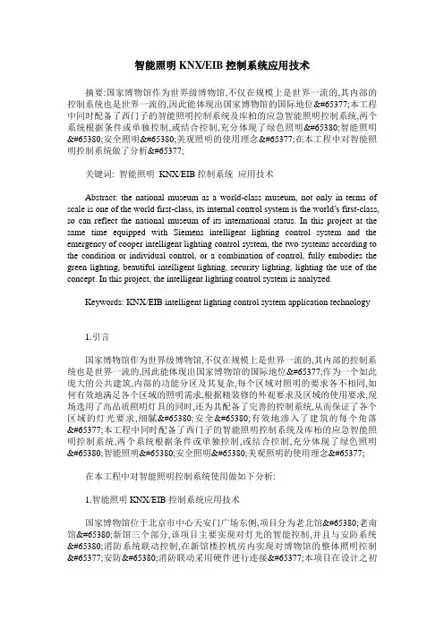
KNX系统的概念"KNX系统"概念起源于二十世纪90年代,现已成为国际标准ISO/IEC14543-3,并于2007年正式成为中国HBES国标GB/Z20965-2007。
该系统通过一条总线将所有的元器件连接起来,每个元器件均可独立工作,同时又可通过中控电脑进行集中监视和控制。
通过电脑编程的各元件既可独立完成诸如开关、控制、监视等工作,又可根据要求进行不同组合,从而实现不增加元件数量而功能却可灵活改变的效果。
施耐德电气KNX系统就是此类产品中的佼佼者。
KNX原理示意图KNX系统的优点:(1)集成控制。
可对灯光、遮阳、空调、地暖等进行集成式控制。
(2)舒适。
创造了安全,健康,宜人的生活及工作环境。
(3)节能。
现代化住宅应在满足使用者对环境要求的前提下,尽量利用自然光及人员活动来调节室照明环境和温度环境,最大限度减少能量消耗。
(4)灵活。
能满足多种用户对不同环境功能的要求。
KNX/EIB系统是开放式,大跨度框架结构,允许用户迅速而方便地改变建筑物的使用功能或重新规划建筑平面。
(5)经济。
自动化提供了实现节能运行与管理的必要条件,同时可大量减少管理与维护人员,降低管理费用,提高劳动效率,并提高管理水平。
(6)安全。
可与消防系统进行联动,当消防报警时,可将正常照明回路强行切断,应急回路强行点亮,从而降低火灾的风险,提高建筑的安全性。
系统元件160mA电源供应器MTN684016电源电压:AC320V,50-60Hz输出电压:DC29V±1V输出电流:最大160mA,防短路模块宽度:5模数=约90mm可为一条最多可带32个总线设备的线路提供总线电压置扼流器,用于隔离总线的供电带开关,用于中断电压并复位连接在线路上的总线设备640mA 电源供应器MTN684064 电源电压:AC320V,50-60Hz输出电压:DC29V±1V输出电流:最大640mA,防短路模块宽度:7模数=约126mm可为一条最多可带64个总线设备的线路提供总线电压置扼流器,用于隔离总线的供电带开关,用于中断电压并复位连接在线路上的总线设备640mA电源供应器(可接应急电源模块) MTN683890电源电压:AC320V,50-60Hz输出电压:DC29V±1V输出电流:最大640mA,防短路模块宽度:7模数=约126mm可为一条最多可带64个总线设备的线路提供总线电压置扼流器,可以隔离电源带开关,用于中断电压并复位连接在线路上的总线设备可连接应急电源REG,以便为总线电压提供缓冲应急电源模块(可接蓄电池) MTN683901电源电压:AC110-230V,50-60Hz输出电压:DC30V±2V输出电流:不带电池,带电网电源:最大300mA;带电池,不带电网电源:最大640mA短路电流<1.5A 充电电流:最大1A设备宽度:4模数=大约72mm用来缓冲总线电压如果出现故障,可将一个电压为DC12V的外部铅酸蓄电池连接到REG电源以便实现缓冲功能电源电压:DC12-30V(在DC24V 40mA),AC12-24V模块宽度:2模数=约36mm可作为快速干线在不同支线之间通过局域网(IP)转发报文控制信号也可用作编程接口,将PC与KNX总线连接起来能够双向转发报文控制信号,最多可对150个控制信号报文进行缓冲处理支线耦合器MTN680204模块宽度:2模数=约36mm可用于支线和区域的逻辑连接和电流隔离逻辑模块676029电流消耗:正常运行情况下约40mA,编程运行情况下约100mA模块宽度:3模数=约54mm置实时定时器按照设定时间标准完成控制操作可以用一个功能元件库根据实际需求制定出通用的应用程序逻辑模块编程软件615014可用功能模块工具软件来编制功能模块REG的应用程序对PC的要求:需有一个空闲的串行接口KNX逻辑模块MTN676090模块宽度:2.5模数=约45mm在KNX系统中,逻辑模块作为逻辑与控制设备带有10个逻辑,10个过滤、定时,8个转换与12个多路(复用)模式带有3个自由编程按钮与3个LED指示灯接口/网关控制面板8键智能面板带耦合器带红外MTN627919(纯白)/MTN627914(烟灰)/MTN627960(银灰)置总线耦合器本面板带有运行指示灯、状态指示灯、标签和8个操作按键每个按键的功能都可以使用一个IR远程控制器来触发防护顶盖为热塑材料,磨光功能:开关、转换、调光、百叶帘、脉冲发送出1、2、4或8为控制信号、2字节控制信号脉冲、8为推移式调节器、场景调用、场景存储、防乱按(防误操作)功能4键多功能面板带LCD温控MTN623244(奶白)/MTN623219(纯白)/MTN623214(烟灰)/MTN623260(银灰)本面板带有运行指示灯、状态指示灯、标签和4个操作按键带有室温控制单元和显示器防护顶盖为热塑材料,磨光多功能按键功能:开关、转换、调光、百叶帘、脉冲发送出1、2、4或8为控制信号、2字节控制信号脉冲、8为推移式调节器、场景调用、场景存储、联锁功能、带有同步化的定时控制、报警功能、周期读取外部温度值、风扇风机控制功能:开关、转换、调光、百叶帘、脉冲发送出1-、2-、4-或8-为控制信号、2字节控制信号脉冲、8位线性调节器、场景恢复、场景存储、乱防按(防误操作)6键智能面板带耦合器MTN628219(纯白)/MTN628260(银灰)/MTN628246(不锈钢,金属)自带总线耦合器本面板带有6个操作键的按键、操作显示器、6个蓝色状态显示器以及一个标签栏功能:开关、转换、调光、百叶帘、脉冲发送出1-、2-、4-或8-为控制信号、2字节控制信号脉冲、8位线性调节器、场景恢复、场景存储、乱防按(防误操作)8键智能面板带耦合器MTN628319(纯白)/MTN628360(银灰)/MTN628346(不锈钢,金属)自带总线耦合器本面板带有8个操作键的按键、操作显示器、8个蓝色状态显示器以及一个标签栏功能:开关、转换、调光、百叶帘、脉冲发送出1-、2-、4-或8-为控制信号、2字节控制信号脉冲、8位线性调节器、场景恢复、场景存储、乱防按(防误操作)8键智能面板带耦合器带红外MTN628419(纯白)/MTN628460(银灰)/MTN628446(不锈钢,金属)自带总线耦合器本面板带有8个操作键的按键、操作显示器、8个蓝色状态显示器以及一个标签栏每个键的功能都可以使用一个IR远程控制器来触发功能:开关、转换、调光、百叶帘、脉冲发送出1-、2-、4-或8-为控制信号、2字节控制信号脉冲、8位线性调节器、场景恢复、场景存储、乱防按(防误操作)4键智能面板带LCD温控MTN628719(纯白)/MTN628760(银灰)/MTN628746(不锈钢,金属)带有4个操作键的便捷操作单元、操作显示器、4个可以单独触发的蓝色状态显示器以及一个标签栏带有室温控制单元和显示器每个键的功能都可以使用一个IR远程控制器来触发功能:开关、转换、调光、百叶帘、脉冲发送出1-、2-、4-或8-为控制信号、2字节控制信号脉冲、8位线性调节器、场景恢复、场景存储、乱防按(防误操作)、具有同步化的定时控制、报警功能、周期读取外部温度值、风扇风机控制带有8个操作键的便捷操作单元、操作显示器、8个可以单独触发的蓝色状态显示器以及一个标签栏 带有室温控制单元和显示器每个键的功能都可以使用一个IR 远程控制器来触发功能:开关、转换、调光、百叶帘、脉冲发送出1-、2-、4-或8-为控制信号、2字节控制信号脉冲、8位线性调节器、场景恢复、场景存储、乱防按(防误操作)、具有同步化的定时控制、报警功能、周期读取外部温度值、风扇风机控制输入模块2路通用输入/输出接口 MTN670802(纯白)每个输入/输出通道:触点电压:< 3V(SELV)触点电流:< 0.5mA输出电流:最大2mA尺寸:约40*30.5*12.5mm(长*宽*高)导线最大长度:30cm 未屏蔽,最多可延长至7.5米(扭绞、未屏蔽导线)在部产生信号电压,用于连接两个常规控制面板或无源触电,并可连接两个低电流LED 指示灯导线长度:最大50m将4个常规控制面板或无源接点连接到KNX部产生一个与总线电隔离的信号电压SELV带总线耦合器2装置宽度:2.5模数=约45mm8路干接点输入模块MTN644592(浅灰)触点电压:最大10V,脉冲控制触点电流:最大约2mA,脉冲形式导线长度:最大50m将8个常规控制面板或无源接点连接到KNX部产生一个与总线电隔离的信号电压SELV带总线连接器和插接螺旋端子装置宽度:4模数=约70mm4路24V信号输入模块MTN644892(浅灰)输入电压:AC/DC 24V输入电流:DC 15mA(30V) AC 6mA(27V)O信号:≤5VI信号:≥11V导线长度:100m装置宽度:2.5模数=约45mm用于将4台带有AC/DC 24输出端的常规设备连接到KNX 带总线耦合器28路24V信号输入模块MTN644792(浅灰)输入电压:AC/DC 24V输入电流:DC 15mA AC 6mA导线长度:100m装置宽度:4模数=约72mm用于将8台带有AC/DC 24输出端的常规设备连接到KNX 带总线耦合器2输入电压:AC 230V,50-60Hz输入电流:AC 12mAO信号:≤40VI信号:≥160V导线长度:100m装置宽度:2.5模数=约45mm用于将4台带有AC 230V输出端的常规设备连接到KNX带总线耦合器28路230V信号输入模块MTN644692(浅灰)输入电压:AC 230V,50-60Hz输入电流:AC 12mA导线长度:100m装置宽度:4模数=约72mm用于将8台带有AC 230V输出端的常规设备连接到KNX带总线耦合器2传感器M系列180度移动感应器带耦合器(墙装) MTN632619(纯白)/MTN632660(银灰)探测围:8m(安装高度为1.1m)探测角度:180度光线感应器:5至2000 Lux之无级感应室移动感应器设计系列180度移动感应器带耦合器(墙装) MTN631819(纯白)/MTN631860(银灰)探测围:8m(安装高度为1.1m)探测角度:180度光线感应器:5至2000 Lux之无级感应室移动感应器检测区域:180度层数:6区域数:46探测围:8m(左右),12m(前方)时间:可以以1秒到8分钟的步长调整,或通过软件设置光传感器:5至2000 Lux之无级感应安装高度:2.2m或1.1m(围的一半)传感器:2个温度测量围:-25度至+55度亮度测量围:1至2000 Lux尺寸:110*72*54mm适合室外安装置总线耦合器用于感应光照度,温度红外遥控器MTN570222(黑色)10信道红外遥控器用于控制所有遥控感应面板、带红外线接收器的百叶帘控制面板、电池:两个微型/小号电池围:最大为20mCONNECT通用遥控器MTN506923(银灰)作为无线射频遥控器和红外遥控器,支持CONNECT无线系统KNX/EIB红外设备最多同时控制5个红外AV设备无线射频围:开放空间100m,室30米红外接收围:最大15米气象站模块MTN682991(浅灰)气象站探测并处理模拟感应器信号最多可以连接4个可自由组合的模拟感应器和组合式天气感应器最多可连接4个可自由组合的模拟感应器辅助电压:AC24V功率:最大4VA输出端:DC24V,100mA装置宽度:4模数=72mm组合式气象传感器MTN663692(黑色)包括一个风速感应器、降水感应器、晨昏光感应器和3个亮度感应器(东、南、西) 置DCF77接收器(带可转动45度的天线)和供暖系统适合安装在户外,可墙上或电杆上辅助电压:AC24V电流消耗:最大600mA风速:1..40m/s亮度:0..110千Lux晨昏光:0..250Lux温度围:-40度..+60度尺寸:130*200mmKNX小型气象站MTN663990(白色)记录、分析并传送天气数据至总线具备一个风速传感器、降水感应器、温度感应器和照度归纳英气适合安装在户外,可墙上或电杆上带总线耦合器电压:AC230V电流消耗:最大10mA带总线电压功率消耗:10W 带加热亮度:0..110千Lux探测围:150度温度围:-20度..+55度尺寸:280*260*135mm处理风速信号并将其转换为一个0-10V的模拟输出电压适合户外安装电压:DC 24V(18-32V DC)电流消耗:12mA输出:0-10V负载:最大60m/s测量围:0.7..40m/s微光传感器(0-10V) 663594(浅灰)用于采集和分析处理亮度通过一个光电二极管测量亮度,并将其转换为0-10V线性模拟输出信号适合户外安装测量围:0至255Lux电压:DC 24V(15-30V DC)电流消耗:5mA输出:0-10V,耐短路尺寸:58*35*64mm温度传感器(0-10V) 663596(浅灰)用于测量温度,并将其转换为0-10V线性模拟输出信号适合户外安装测量围:-30度至+70度电压:DC 24V(15-30V DC)电流消耗:3mA输出:0-10V,耐短路尺寸:58*35*64mm定时器通过通常开触点独立开关4个负载带置总线耦合器与螺丝接线端额定电压:AC 230V,50-60Hz额定电流:10A额定功率:AC 230V,最大2300VA 白炽灯:AC 230V,最大2300W卤素灯:AC 230V,最大1700W荧光灯:AC 230V,最大1800W电容负载:AC 230V,最大16A装置宽度:2.5模数=约45mm4路16A开关控制模块MTN647593(浅灰)通过通常开触点独立开关4个负载带置总线耦合器与螺丝接线端额定电压:AC 230V,50-60Hz额定电流:16A白炽灯:AC 230V,最大3600W卤素灯:AC 230V,最大2500W荧光灯:AC 230V,最大2500VA电容负载:AC 230V,最大16A装置宽度:4模数=约72mm8路6A开关控制模块MTN646808(浅灰)通过通常开触点可对8路负载进行相互独立的开关操作带置总线耦合器2与螺纹端口或插装式螺纹端口额定电压:AC 230V,50-60Hz额定电流:6A白炽灯:AC 230V,最大1380W卤素灯:AC 230V,最大1380W荧光灯:AC 230V,最大1000W电容负载:AC 230V,6A装置宽度:4模数=约72mm白炽灯:AC 230V,最大3600W卤素灯:AC 230V,最大2500W荧光灯:AC 230V,最大2500VA电容负载:AC 230V,最大16A装置宽度:12模数=约216mm2路16A开关控制模块带电流检测MTN647395(浅灰)通过通常开触点独立开关2个负载带手动开关,置总线耦合器额定电压:AC 230V,50-60Hz额定电流:16A白炽灯:AC 230V,最大3600W卤素灯:AC 230V,最大2500W荧光灯:AC 230V,最大2500VA电容负载:AC 230V,最大16A马达负载:AC 230V,最大1000W检测围:0.1A 至16A频率:50/60Hz装置宽度:2.5模数=约45mm额定电流:16A白炽灯:AC 230V,最大3600W卤素灯:AC 230V,最大2500W荧光灯:AC 230V,最大2500VA 带并联补偿电容负载:AC 230V,最大16A马达负载:AC 230V,最大1000W检测围:0.1A 至16A频率:50/60Hz装置宽度:8模数=约144mm12路16A开关控制模块带电流检测MTN647895(浅灰)通过通常开触点独立开关12个负载带手动开关,置总线耦合器额定电压:AC 230V,50-60Hz额定电流:16A白炽灯:AC 230V,最大3600W卤素灯:AC 230V,最大2500W荧光灯:AC 230V,最大2500VA 带并联补偿电容负载:AC 230V,最大16A马达负载:AC 230V,最大1000W检测围:0.1A 至16A频率:50/60Hz装置宽度:12模数=约216mm12路16A开关控制模块带电流检测MTN648495(浅灰)通过通常开触点独立开关12个负载带手动开关,置总线耦合器额定电压:AC 230V,50-60Hz额定电流:16A白炽灯:AC 230V,最大3600W卤素灯:AC 230V,最大2500W荧光灯:AC 230V,最大2500VA 带并联补偿电容负载:AC 230V,最大16A马达负载:AC 230V,最大1000W检测围:0.1A 至16A频率:50/60Hz装置宽度:12模数=约216mm通过通常开触点独立控制8个百叶窗/卷帘驱动器或者开关最多16个负载可通过安检操作来人工操作所有百叶窗/开关输出,带有置总线连接器额定电压:AC 110-240V,50-60Hz外部辅助电压:AC 230V,50-60Hz,最大2VA每个百叶窗输出:额定电流:10A电机负载:AC 230V,最大1000W每个开关输出:额定电流:10A白炽灯:AC 230V,最大2000W卤素灯:AC 230V,最大1700W荧光灯:AC 230V,最大1800VA,带并联补偿荣性负载:AC 230V装置宽度:8模数=约144mm12路百叶窗或24路10A开关控制模块MTN649912(浅灰)通过通常开触点独立控制12个百叶窗/卷帘驱动器或者开关最多24个负载可通过安检操作来人工操作所有百叶窗/开关输出,带有置总线连接器额定电压:AC 230V,50-60Hz外部辅助电压:AC 110-240V,50-60Hz,最大2VA每个百叶窗输出:额定电流:10A电机负载:AC 230V,最大1000W每个开关输出:额定电流:10A白炽灯:AC 230V,最大2000W卤素灯:AC 230V,最大1700W荧光灯:AC 230V,最大1800VA,带并联补偿荣性负载:AC 230V装置宽度:8模数=约144mm4路24VDC百叶窗控制模块MTN648704(浅灰)通过常开触点独立控制最多4个百叶窗/卷帘驱动器所有百叶窗输出端均可用按键进行手动操作,带有置总线连接器每个百叶窗输出:额定电压:DC 24V±10%额定电流:6A负载类型:24V直流驱动器装置宽度:4模数=约72mm4路230V卷帘控制模块MTN649704(浅灰)用于对4台卷帘驱动装置进行相互独立的控制所有卷帘输出端均可用按键进行手动操作,带有置总线连接器每个卷帘输出:额定电压:AC 230V,50-60Hz额定电流:10A电机负载:AC 230V,最大1000W装置宽度:4模数=约72mm4路230V百叶窗控制模块MTN649804(浅灰)用于对4台百叶窗驱动装置进行相互独立的控制所有百叶窗输出端均可用按键进行手动操作,带有置总线连接器每个百叶窗输出:额定电压:AC 230V,50-60Hz额定电流:10A电机负载:AC 230V,最大1000W装置宽度:4模数=约72mm装置宽度:8模数=约144mm调光执行器/控制单元单路500W通用调光模块MTN649350(浅灰)借助可调光的绕线式或电子式变压器对白炽灯、高压卤素灯和低压卤素灯进行开关/调光操作能够自动识别连接的负载,不能连接感性负载与容性负载的组合带有置总线耦合器额定电压:AC 220-230V,50-60Hz额定功率/信道:最大500W/VA最低负载(阻性)20W最低负载(阻性-感性-容性) 50VA输入端(辅控操作):AC 230V,50-60Hz(与调光信道处于同一相位)装置宽度:4模数=约72mm单路1000W通用调光模块MTN649310(浅灰)借助可调光的绕线式或电子式变压器对白炽灯、高压卤素灯和低压卤素灯进行开关/调光操作能够自动识别连接的负载,不能连接感性负载与容性负载的组合带有置总线耦合器额定电压:AC 220-230V,50-60Hz额定功率/信道:最大1000W/VA最低负载(阻性)20W最低负载(阻性-感性-容性) 50VA输入端(辅控操作):AC 230V,50-60Hz(与调光信道处于同一相位)装置宽度:4模数=约72mm4路150W通用调光模块MTN649315(浅灰)借助可调光的绕线式或电子式变压器对白炽灯、高压卤素灯和低压卤素灯进行开关/调光操作能够自动识别连接的负载,不能连接感性负载与容性负载的组合带有置总线耦合器额定电压:AC 220-230V,50-60Hz额定功率/信道:最大150W/VA最低负载(阻性)20W最低负载(阻性-感性-容性) 50VA输入端(辅控操作):AC 230V,50-60Hz(与调光信道处于同一相位)装置宽度:6模数=约105mm单路日光灯调光模块(0-10V) MTN647091(浅灰)用来把带有0-10V接口的设备连接到KNX带有置的总线连接器以及螺接端子(230V)或插接螺旋端子(0-10V) 230V开关输出可以使用一个人工开关来操作开关触点:用来开关电子镇流器/变压器开关电压:AC 230V开关电流:16A开关容量:AC 230V,3600W容性负载:AC 230V,3600W卤素灯:AC 230V,2500W荧光灯:AC 230V,最大5000W,无补偿AC 230V,最大2500W,带有并联补偿0-10V接口:用来调节电子镇流器/变压器电压围:DC 0-10V装置宽度:2.5模数=约45mmAC 230V,最大2500W,带有并联补偿0-10V接口:用来调节电子镇流器/变压器电压围:DC 0-10V装置宽度:4模数=约72mm单路DALI网关MTN680191(浅灰)DALI网关将KNX与数字EVG(需装配DALI接口)相连可以对16组至多64个EVGA进行开关和调光操作,并可控制16个灯光场景带有两个输入端,用于连接入控制面板等设备开关触点:用来开关电子镇流器/变压器供电电压:AC 110-240V,50-60Hz输入端:2,被动模式DC 9-36V 或AC 9-24V输出端:DALI D+,D负荷DALI规DC 16-18V,150mA,防短路连接导线:1.5-2.5mm装置宽度:6模数=约108mm触摸屏及温控面板10寸触摸屏MTN683090(银白色,有光泽)用来显示和控制建筑的当前状态和功能带有局域网以及一个RS232和USB接口安装的操作系统是Windows CE显示器尺寸:10.4寸分辨率800*600像素,SVGA显示器类型:TFT,电阻式触摸显示器电网电压:DC 24V功耗:< 20WRAM:128MB边框尺寸:224.7*277.5*12mm(高*宽*厚)开口:157.4*210.2mm(高*宽)10寸触摸屏纯玻璃边框MTN489960(水晶色)用于10寸触摸板的装饰边框尺寸:228.6*281.4*13.5mm(高*宽*厚)。
KNX系统的概念"KNX系统"概念起源于二十世纪90年代,现已成为国际标准ISO/IEC14543-3,并于2007年正式成为中国HBES国标GB/Z20965-2007。
该系统通过一条总线将所有的元器件连接起来,每个元器件均可独立工作,同时又可通过中控电脑进行集中监视和控制。
通过电脑编程的各元件既可独立完成诸如开关、控制、监视等工作,又可根据要求进行不同组合,从而实现不增加元件数量而功能却可灵活改变的效果。
施耐德电气KNX系统就是此类产品中的佼佼者。
KNX原理示意图KNX系统的优点:(1)集成控制。
可对灯光、遮阳、空调、地暖等进行集成式控制。
(2)舒适。
创造了安全,健康,宜人的生活及工作环境。
(3)节能。
现代化住宅应在满足使用者对环境要求的前提下,尽量利用自然光及人员活动来调节室内照明环境和温度环境,最大限度减少能量消耗。
(4)灵活。
能满足多种用户对不同环境功能的要求。
KNX/EIB系统是开放式,大跨度框架结构,允许用户迅速而方便地改变建筑物的使用功能或重新规划建筑平面。
(5)经济。
自动化提供了实现节能运行与管理的必要条件,同时可大量减少管理与维护人员,降低管理费用,提高劳动效率,并提高管理水平。
(6)安全。
可与消防系统进行联动,当消防报警时,可将正常照明回路强行切断,应急回路强行点亮,从而降低火灾的风险,提高建筑的安全性。
系统元件160mA电源供应器 MTN684016电源电压:AC320V,50-60Hz输出电压:DC29V±1V输出电流:最大160mA,防短路模块宽度:5模数=约90mm可为一条最多可带32个总线设备的线路提供总线电压内置扼流器,用于隔离总线的供电带开关,用于中断电压并复位连接在线路上的总线设备640mA电源供应器 MTN684064电源电压:AC320V,50-60Hz输出电压:DC29V±1V输出电流:最大640mA,防短路模块宽度:7模数=约126mm可为一条最多可带64个总线设备的线路提供总线电压内置扼流器,用于隔离总线的供电带开关,用于中断电压并复位连接在线路上的总线设备640mA电源供应器(可接应急电源模块) MTN683890电源电压:AC320V,50-60Hz输出电压:DC29V±1V输出电流:最大640mA,防短路模块宽度:7模数=约126mm可为一条最多可带64个总线设备的线路提供总线电压内置扼流器,可以隔离电源带开关,用于中断电压并复位连接在线路上的总线设备可连接应急电源REG,以便为总线电压提供缓冲应急电源模块(可接蓄电池) MTN683901电源电压:AC110-230V,50-60Hz输出电压:DC30V±2V输出电流:不带电池,带电网电源:最大300mA;带电池,不带电网电源:最大640mA短路电流<1.5A 充电电流:最大1A设备宽度:4模数=大约72mm用来缓冲总线电压如果出现故障,可将一个电压为DC12V的外部铅酸蓄电池连接到REG电源以便实现缓冲功能电源电压:DC12-30V(在DC24V 40mA),AC12-24V模块宽度:2模数=约36mm可作为快速干线在不同支线之间通过局域网(IP)转发报文控制信号也可用作编程接口,将PC与KNX总线连接起来能够双向转发报文控制信号,最多可对150个控制信号报文进行缓冲处理支线耦合器 MTN680204模块宽度:2模数=约36mm可用于支线和区域的逻辑连接和电流隔离逻辑模块 676029电流消耗:正常运行情况下约40mA,编程运行情况下约100mA模块宽度:3模数=约54mm内置实时定时器按照设定时间标准完成控制操作可以用一个功能元件库根据实际需求制定出通用的应用程序逻辑模块编程软件 615014可用功能模块工具软件来编制功能模块REG的应用程序对PC的要求:需有一个空闲的串行接口KNX逻辑模块 MTN676090模块宽度:2.5模数=约45mm在KNX系统中,逻辑模块作为逻辑与控制设备带有10个逻辑,10个过滤、定时,8个转换与12个多路(复用)模式带有3个自由编程按钮与3个LED指示灯电话网关 MTN680790供电电源:DC 12-24V功耗:90mA/24V(开路),790mA at 24V(最大负荷)开关输出:6个,100mA/12V/24V报警输出:1个,100mA/12V/24V信号输入:6个,干接点电话:模拟,CTR21,线长3米RS 232:线长3米模块宽度:8模数=约144mm电话网关用于连接电话和KNX系统或传统的输入/输出最多可控制或显示20个KNX设备控制面板M系列2键智能面板带耦合器 MTN627519(纯白)/MTN627514(烟灰)/MTN627560(银灰)内置总线耦合器本面板带有运行指示灯、状态指示灯、标签和2个操作按键防护顶盖为热塑材料,磨光功能:开关、转换、调光、百叶帘、脉冲发送出1、2、4或8为控制信号、2字节控制信号脉冲、8为推移式调节器、场景调用、场景存储、联锁功能4键智能面板带耦合器 MTN627619(纯白)/MTN627614(烟灰)/MTN627660(银灰)内置总线耦合器本面板带有运行指示灯、状态指示灯、标签和4个操作按键防护顶盖为热塑材料,磨光功能:开关、转换、调光、百叶帘、脉冲发送出1、2、4或8为控制信号、2字节控制信号脉冲、8为推移式调节器、场景调用、场景存储、联锁功能8键智能面板带耦合器带红外 MTN627919(纯白)/MTN627914(烟灰)/MTN627960(银灰)内置总线耦合器本面板带有运行指示灯、状态指示灯、标签和8个操作按键每个按键的功能都可以使用一个IR远程控制器来触发防护顶盖为热塑材料,磨光功能:开关、转换、调光、百叶帘、脉冲发送出1、2、4或8为控制信号、2字节控制信号脉冲、8为推移式调节器、场景调用、场景存储、防乱按(防误操作)功能4键多功能面板带LCD温控 MTN623244(奶白)/MTN623219(纯白)/MTN623214(烟灰)/MTN623260(银灰)本面板带有运行指示灯、状态指示灯、标签和4个操作按键带有室温控制单元和显示器防护顶盖为热塑材料,磨光多功能按键功能:开关、转换、调光、百叶帘、脉冲发送出1、2、4或8为控制信号、2字节控制信号脉冲、8为推移式调节器、场景调用、场景存储、联锁功能、带有同步化的定时控制、报警功能、周期读取外部温度值、风扇风机控制8键多功能面板带LCD温控 MTN633614(烟灰)/MTN633610(银灰)本面板带有运行指示灯、状态指示灯、标签和8个操作按键带有室温调控器和显示器带内置压电蜂鸣器,用于显示报警状态和红外线接收器每个按键的所有功能都可以通过远距离红外线遥控器进行操作防护顶盖为热塑材料,磨光多功能按键功能:开关、转换、调光、百叶帘、脉冲发送出1、2、4或8为控制信号、2字节控制信号脉冲、8为推移式调节器、场景调用、场景存储、联锁功能、带有同步化的定时控制、报警功能、周期读取外部温度值、风扇风机控制单联翘板KNX连接单元 MTN625199控制面板模块,不带面板。
施耐德电气KNX/EIB系统设计手册2008现代社会随着计算机技术、网络技术、通讯技术的发展, 智能建筑的概念逐渐深入人们的生活。
人们对建筑的要求有了进一步的提升,除了传统需求,舒适性,安全性,高效性,方便性,可靠性甚至节能性都在考虑范围内,这使得智能建筑控制系统成为必然趋势。
施耐德电气KNX/EIB系统对灯光、空调及遮阳的自动监控功能,满足了使用者对智能资源的使用和管理需要,先进的软硬件设施为使用者和管理者提供了舒适宜人的生活意境和灵活高效的办公环境。
目 录第一章 KNX/EIB系统简介 /3第二章 KNX/EIB系统设计例图 /7第三章 KNX/EIB系统与BA的连接方法 /11第四章 KNX/EIB系统施工说明 /12第五章 KNX/EIB选型一览表 /13第六章 KNX/EIB系统部分业绩 /223第一章 KNX/EIB系统简介KNX/EIB系统的概念 "KNX/EIB系统"概念起源于二十世纪90年代,现已成为国际标准ISO/IEC14543-3,并于2007年正式成为中国HBES国标GB/Z 20965-2007。
该系统通过一条总线将所有的元器件连接起来,每个元器件均可独立工作,同时又可通过中控电脑进行集中监视和控制。
通过电脑编程的各元件既可独立完成诸如开关、控制、监视等工作,又可根据要求进行不同组合,从而实现不增加元件数量而功能却可灵活改变的效果。
施耐德电气KNX/EIB系统就是此类产品中的佼佼者。
KNX/EIB系统的优点:(1)集成控制。
可对灯光、遮阳、空调、地暖等进行集成式控制。
(2)舒适。
创造了安全,健康,宜人的生活及工作环境。
(3)节能。
现代化住宅应在满足使用者对环境要求的前提下,尽量利用自然光及人员活动来调节室内照明环境和温度环境,最大限度减少能量消耗。
(4)灵活。
能满足多种用户对不同环境功能的要求。
KNX/EIB系统是开放式,大跨度框架结构,允许用户迅速而方便地改变建筑物的使用功能或重新规划建筑平面。