法国尚飞RTS样本产品手册
- 格式:pdf
- 大小:1.80 MB
- 文档页数:8


Commercial Unit (110 vac)B290400O P E R A T I N G M A N U A LACTISOL COMMERCIAL UNITOPERATING MANUALThank you and Congratulations on your choice of the Actisol®Commercial Unit, a revolutionary insecticide delivery system that uniquely combines the technology of foggers, misters, refillable sprayers and prepackaged aerosols.This refillable unit eliminates the need for costly prepackaged aerosols by mechanically generating the most optimum-sized, uniform insecticide particles. Its unique design allows you to treat more area per ounce than with pre-packaged aerosol products.It’s mobile, practical, and durable design make s it a valuable tool for all commercial accounts. In addition, it gives you the flexibility of using a variety of insecticides that are EPA approved for use in this type of equipment.Best of all, the Actisol® Commercial Unit provides deep harborage insect control, something you won’t get from pre-packaged aerosol products or conventional delivery systems. This system combines the right amount of insecticide with a high volume of moderately pressurized air to improve penetration through cracks and crevices to reach target insects deep within ceiling and wall voids. The Actisol® Commercial Unit eliminates insects in places other delivery systems can’t even reach.Manufactured in the USA By:Environmental Delivery Systems, Inc.314 Morningside DriveFriendswood, TX 77546OPERATING INSTRUCTIONSHandle with care.Do not place the unit where vibration and surface conditions would allow it to fall. Keep the unit on the ground when in use.Always wear personal protective equipment.When filling these units always wear protective eyewear and protective gloves. When operating these units, always wear protective clothing, eyewear, chemical resistant rubber gloves, and a respirator. Refer to the insecticide label for specific instructions and other precautions.1.Prepare area to be treated.Refer to insecticide label for directions on proper preparation for area to be treated before operating this equipment. General preparation includes:A.Remove all people and pets from the area to be treated.B.Remove all food, dishes, silverware, utensils or similar items that could come into contactwith the insecticide.C.Make sure all ventilation systems are turned off and windows are closed.D.Identify all areas where fire could result such as pilot lights or open flames.E.Make sure all aquarium filters and pumps are turned off and the tanks or ponds coveredto prevent contamination.2. Filter insecticide and fill tank.Turning counter clockwise remove fill cap (Item # 75) from tank. Filter insecticide by pouring slowly into fill neck and through the 50 mesh drop-in tank filter (Item # 74) to remove any debris that may clog or damage the Commercial Unit. DO NOT OVERFILL. If tank is too full it will overflow when the system is back flushed, as recommended. For best results fill tank about 80% full.3. Replace fill cap.Turning the cap clockwise, hand-tighten until firmly secured.4. Plug in / turn on power.A. Plug the Commercial Unit into a three-prong grounded, 110/115-volt electrical source. Use an additional three-prong grounded heavy-duty extension cord when operating this unit (Additional Cord Not Included).B. Remove red tip protector cap (Item # 34 - not shown in diagram) from the tip of the wand.C. Switch the unit to the ON position using the ON/OFF switch (Item # 79) located in the back of the unit on the right hand side.5. Adjust regulator.To adjust regulator (Item # 43) start by unlocking the safety lock located on the adjustment knob by pulling up on the knob. If a red ring is present, lift up on the red ring to unlock. Turn the knob slowly clockwise until the 0-30 psi back mount gauge (Item # 58) reads 17 - 20 psi.6. Purge air bubbles.Air pockets that develop may delay the shutoff of the aerosol after the trigger is released. To remove air pockets from the system turn the unit off, point the applicator tip into the original insecticide container, depress the trigger and wait until a pinstream flows from the tip. Hold for approximately 10 seconds to fully purge the system and allow for an uninterrupted pinstream.7. Turn the unit on to begin use.At this point the air flows freely through the twin tubing to the wand and excess air is vented to atmosphere at the tip. Next, the air flows into the regulator which controls the pressure exerted on the liquid inside the tank. The liquid product then travels through the second line of the twin tubing to the wand.8. Apply insecticide.A. Apply insecticide according to label instructions.B. Position the applicator tip on desired target.C. Depress the trigger to apply insecticide.Always apply insecticide according to the label instructions. Position the applicator tip on the desired target and depress the trigger to apply insecticide. Releasing the trigger allows the unit’s free airflow to push the already app lied insecticide deeper into harborage areas. The compressed air is environmentally safe and much more effective than chemical propellants. The free flowing air stream will also disturb target insects even without the use of liquid. The continuous free flowing air stream allows for deeper penetration of the target areas.The comfortable precision wand is balanced, easy to use, and easy to maintain. This unique wand is based on a common industry design making it simple to repair with easy access to replacement parts.Helpful Hints: Occasionally, when working overhead, the pressure exerted on the liquid tank by the regulator will not be sufficient to drive the liquid 8-10 feet above floor level.At this time, you need to increase the pressure on the liquid tank by adjusting the regulator clockwise to the point you receive the aerosol at the tip and at the height you desire to work.When operating the Actisol®System particle size may vary with pressure, but not as much as you think. What actually occurs is a higher rate of flow. In other words, you are using more liquid than needed to produce aerosol. The aerosols that you’ve probably used in the past were driven by propellant. Therefore, you saw larger particles and most of the material that was visible was that of the propellant. The Actisol® System utilizes no propellant. All you are seeing is the pesticide that has been sheared into micron sized particles. 98% are in the 2.4 to 15 micron size range. By increasing the pressure on the liquid tank you only increase the flow rate. The result being, using more pesticide than is required to do the job.9. Turn off unit / release pressure from tank.When necessary, switch the unit to the OFF position (Item # 79).To relieve pressure in the tank, press down on the pressure relief valve (Item # 69) located on the top of the fill cap (Item # 75).10. Back Flush System After Every Use to Remove Chemical From Wand and Hose.This procedure is highly recommended and is the mostimportant maintenance you can do for your system.A.Switch unit to the ON position (Item # 79).B.Turn regulator knob (Item # 43) counter clockwise until it stops.C.Relieve pressure in the tank by pressing down on the pressurerelief valve (Item # 69).D.Unscrew fill cap (Item # 75) by turning counter clockwise andremove.E.Holding the wand over the tank, place gloved finger over integrated stainless crack &crevice tip (Item # 2) exit orifice, stopping the flow of air, then squeeze the application trigger (Item # 23) until liquid is purged from the wand and hose. You will hear a gurgling sound coming from the tank when the process is complete. This process should take about 10 seconds.F.Remove gloved finger from tip and release trigger.G.Switch unit to OFF position (Item # 79).H.Replace fill cap (Item # 75) and tighten.I.Position red tip protector cap (Item # 34) over tip of wand for transportation of unit.Note: Back flush procedure should be performed after each use. This will help protect the polyurethane rubber hose in the wand (Item # 9) and the 50’ red twin tubing (Item # 61) and prevents unwanted spillage during transportation.11. Using the air chuck.The Commercial Unit is equipped with a 100 psi. capable airchuck (Item # 55) designed to pressurize a pneumatic duster, acompressed air sprayer fitted with an air valve (not included)and/or a tire of a service vehicle.To use the air chuck the compressor (Item # 31) must be running.Turn the handle of the ball valve (Item # 59), located on themanifold (Item # 78), in the cross line position. The adjustable 100 psi relief valve (Item #42) will relieve and produce a notable popping sound.Fit the air chuck on the pneumatic pressure duster, compressed air sprayer (fitted with an air valve) and pressu rize according to the equipment’s operating instructions.You can watch the pressure build on the 0-160 back mount gauge (Item # 56) and remove when desired pressure is reached.Note:The pressure relief valve is adjustable and should be preset to desired maximum pressure prior to use. Factory setting is 80 psi.12.Transporting the unit.Wrap the red twin hose (Item # 61) around the units storage cleats located on each side of the cart. To prevent bending or kinking the hose, avoid wrapping the hose too tight. Transport the Commercial Unit in an upright position. Take care not to damage the integrated crack & crevice tip (Item # 2) by positioning the red tip protector cap (Item # 34) over tip of wand after every use.Draining the Tank & Back Flushing1. Draining the tank.Drain the Commercial Unit’s tank when changing insecticides or storingfor an extended period of time.A.Switch unit to the ON position (Item # 79).B.Turn regulator knob (Item # 43) clockwise until 0-30 psi back mountgauge (Item # 58) reads 10-15 psi.C.Place drain tube (Item # 38) extending from the drain valve, intooriginal insecticide container.D.Turn handle on the tank drain valve assembly (Item # 64), it is locatedon the bottom right of the tank.E.Allow liquid to flow through tube into container until the tank isempty and air flows through the tube.F.Turn regulator knob (Item # 43) counter clockwise until it stops.2.Back flushing the system will remove chemical from wand and hose.This procedure should be performed after each use. This will helpprotect the polyurethane rubber hose in the wand (Item # 9) and the50’ red twin tubing (Item # 61) and prevents spillage duringtransportation.A. Place gloved finger over integrated crack & crevice tip (Item # 2) exitorifice, stopping the flow of air, then squeeze the application trigger(Item # 23) until liquid is purged from the wand and hose. You willhear a gurgling sound coming from the container and you will see nomore liquid traveling through the drain tube, only air will flow through drain tube when the process is complete. This process should take about 10 seconds.B. Remove gloved finger from tip and release trigger.C. Switch unit to OFF position (Item # 79).D. Replace fill cap (Item # 69) and tighten.E. Close the tank drain valve assembly (Item # 64).F. Position red tip protector cap (Item #34) over tip of wand for transportation of unit. Diagnosis and Field Service1.The unit is running and air is flowing from the tip, but no chemical aerosol is beingproduced.A.Make sure the tank contains insecticide.Remove tank cap (Item # 75), inspect tank for liquid. If there is no liquid in the tank, fill at least 25%.B.Check 50’ red twin tubing (Item # 61)) for kinks, crimps, twists, or other factors thatwould obstruct chemical flow to the wand.Unwrap the hose to free from kinking, crimping or blockage.C.Check the 0-30 pressure gauge (Item # 58).With the compressor running, it should read 17-20 psi.D.Be sure air pressure is reaching the wand tip.You should be able to hear and feel air flowing from the tip of the wand.E. Check for liquid flow with no air flow.Turn unit off, leave pressure in the tank, point the wand into the original insecticide container, and depress the trigger until a pinstream flows from the tip.If a pinstream flows from the tip with the compressor off and the tank under pressure:Remove integrated crack & crevice tip (Item # 2). Exit orifice should be maintained at .046”or use a drill bit #56. Drill exit orifice to resize.When used on abrasive surfaces the tip tends to close up reducing the amount of air that can escape resulting in excessive backpressure on the liquid.Also, be sure that all orifices in the fluid cap (Item # 5) are free of debris. Replace tip assembly and follow operating instructions to generate aerosol.F. If no liquid flow or pin stream, inspect fluid cap (Item # 5) by removing tip (Item # 2)and removing any debris from all orifices.2.The unit is running and the aerosol will not shut off at the tip when trigger is released.A.Unit may have air pockets created by surfaces forcing air back into the tip duringapplication.a.To release air pockets depress trigger and hold while aerosol is released. You will seeintermittent surges of aerosol, hold trigger until aerosol flows consistently withoutinterruption.b.Another method is to turn off the compressor and point tip into original insecticidecontainer and squeeze trigger to produce a pin stream. Allow to flow untiluninterrupted.B.Teflon seat (Item # 10) may be damaged or contain debris preventing positiveshutoff.First follow instructions for step number 10 of operating instructions to backflush liquid.Remove stainless airline (Item # 26) by removing compression nut at the elbow (Item # 32) to adapter body (Item # 8). Then remove adapter body (Item # 8) attached to valve body (Item # 12). Check exposed seat for debris, nicks, and scratches. Replace if necessary. Also inspect seat stem surface (Item # 24) for scratches or nicks. Replace if necessary.3.Airflow is low and aerosol is too heavy at normal 17 – 20 psi operating pressure.A.Fluid cap (Item # 5) may be damaged.Remove integrated crack & crevice tip (Item # 2). Inspect fluid cap (Item # 5) for cracks and debris around the air holes. The wheel should be stationary. It should not wiggle, spin or be crooked or smashed.B.Unit may be losing pressure due to a leak.With pressure in the tank, turn unit off and inspect for leaks at the pressure relief valve (Item # 69) and the tank cap o-ring (Item # 70). With the unit running inspect the 50’ red twin tubing (Item # 61) and entire wand in areas where air could escape, such as welds or fittings.Inspect for air leakage at the air chuck (Item # 55).4.While working with wand over-head air is flowing from the tip, but no chemical aerosolis being produced.A.A higher liquid pressure is necessary when wand is higher than 6’ from unit. Tocompensate simply adjust regulator (Item # 43) clockwise in one or two psi increments until desired flow is reached.Note: When returning to ground level operations reduce pressure by turning regulator (Item # 43) counter clockwise and releasing pressure from the tank by pushing the button on the pressure relief valve (Item # 69) until reaching 17 - 20 psi on gauge.If none of these solutions corrects your problem, there may be something more serious wrong with the unit. For additional technical assistance please contact Environmental Delivery Systems, Inc. Technical Services Department.Insecticides1. Observe label directions.Do not operate the Actisol®Commercial Unit with insecticides notlabeled for aerosol, fog or mist applications. Read the insecticide labelto determine if the insecticide is EPA- approved for use in this type ofequipment. Contact your chosen distributor for Information oninsecticides currently labeled for use in equipment such as ActisolDelivery Systems.PartsParts for the Actisol® Commercial Unit can be ordered through your chosen distributor. When ordering spare or replacement parts refer to the exploded diagram and the product codes on the parts list in this manual.ServiceIf the Actisol® Commercial Unit requires factory service be sure to drain the tank, back flush the wand and hose, and pack the unit in its original carton and packing material for shipping. If the original carton is not available, pack the unit a durable box and protect the unit as best you can. If using foam packing materials be sure to place the unit in a plastic bag before adding materials to carton.Ship the unit with a description of the problem, a contact name and phone number, and a return shipping address to:Environmental Delivery Systems, Inc.314 Morningside DriveFriendswood, TX 77546281-993-0019 – PhoneNote: Post warranty service will be billed for parts, labor, packaging (if needed), and freight.2342835NOTE:Item #2 Exit Orifice inside diameter must be maintained at or about 0.046 or use a # 56 drill bit.2 3428 35 NOTE: Item #2 Exit Orifice inside diameter must be maintained at or about 0.046 or use a # 56 drill bit. ACTISOL ® WAND —18”ACTISOL® WAND –18”74767950494549ACTISOL® COMMERCIAL UNIT EXPOLDEDPRODUCT LIMTED WARRANTYEnvironmental Delivery Systems, Inc. and it’s products are warranted to be defect free in materials and workmanship under normal use, for a period of (1) year from the date of manufacture or (1) year of use, with proof of purchase. This limited warranty will not exceed (2) years, in any event.Environmental Delivery Systems, Inc. shall not be liable for freight damage incurred during shipping. Package returns carefully. If the original carton is not available, pack the unit in a durable box and protect the unit as best you can. If using foam packing materials, be sure to place the unit in a plastic bag before adding materials to carton.Environmental Delivery Systems, Inc.’s obligation under this warranty policy is limited to the repair or replacement of the unit. All returns will be tested per Environmental Delivery Systems, Inc. factory criteria. Units found not defective, under the terms of this limited warranty, are subject to the charges paid by the returnee.Warranty replacement will be shipped on a freight allowed basis. Environmental Delivery Systems, Inc. reserves the right to choose the method of transportation.This limited warranty is in lieu of all other warranties, expressed or implied, and no other person is authorized to give any other warranty or assume obligation or liability on Environmental Delivery Systems, Inc.’s behalf. Environmental Delivery Systems, Inc. shall not be li able for any labor, damage or other expense, nor shall Environmental Delivery Systems, Inc. be liable for any indirect, incidental or consequential damages of any kind incurred by the reason of the use or sale of any defective product or part.Return PolicyAll units must be flushed of any chemicals before shipping. Carriers, including U.S.P.S., airlines, UPS, ground freight, etc. require specific identification of any hazardous materials to be shipped. Failure to do so may result in a substantial fine and/or prison term. Check with your shipping company for specific instructions.All Units must be flushed of any chemical (ref. OSHA Section 1910.1200 (d)(e)(f)(g)(h)) and NO hazardous chemicals will be accepted for service or warranty consideration. Environmental Delivery Systems, Inc. reserves the right to request a Material Safety Data Sheet from the returnee for any product it deems necessary. Environmental Delivery Systems, Inc. reserves the right to “disposition as scrap” any products returned wh ich contain unknown fluids. Environmental Delivery Systems, Inc. reserves the right to charge the returnee for all costs incurred for chemical testing and proper disposal of components containing unknown fluids. Environmental Delivery Systems, Inc. requests this in order to protect the environment and personnel from the hazards of handling unknown fluids.。
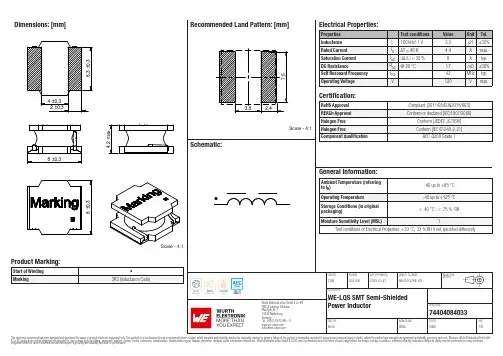
Dimensions: [mm]Scale - 4:174404084033BC74404084033T e m p e r a t u r eT pT L74404084033Cautions and Warnings:The following conditions apply to all goods within the product series of WE-LQS of Würth Elektronik eiSos GmbH & Co. KG:General:•This electronic component is designed and manufactured for use in general electronic equipment.•Würth Elektronik must be asked for written approval (following the PPAP procedure) before incorporating the components into any equipment in fields such as military, aerospace, aviation, nuclear control, submarine, transportation (automotive control, train control, ship control), transportation signal, disaster prevention, medical, public information network etc. where higher safety and reliability are especially required and/or if there is the possibility of direct damage or human injury.•Electronic components that will be used in safety-critical or high-reliability applications, should be pre-evaluated by the customer. •The component is designed and manufactured to be used within the datasheet specified values. If the usage and operation conditions specified in the datasheet are not met, the wire insulation may be damaged or dissolved.•Do not drop or impact the components, the component may be damaged.•Würth Elektronik products are qualified according to international standards, which are listed in each product reliability report. Würth Elektronik does not warrant any customer qualified product characteristics beyond Würth Elektroniks’ specifications, for its validity and sustainability over time.•The responsibility for the applicability of the customer specific products and use in a particular customer design is always within the authority of the customer. All technical specifications for standard products also apply to customer specific products.Product specific:Soldering:•The solder profile must comply with the technical product specifications. All other profiles will void the warranty.•All other soldering methods are at the customers’ own risk.•Strong forces which may affect the coplanarity of the components’ electrical connection with the PCB (i.e. pins), can damage the part, resulting in avoid of the warranty.Cleaning and Washing:•Washing agents used during the production to clean the customer application might damage or change the characteristics of the wire insulation, marking or plating. Washing agents may have a negative effect on the long-term functionality of the product.•Using a brush during the cleaning process may break the wire due to its small diameter. Therefore, we do not recommend using a brush during the PCB cleaning process.Potting:•If the product is potted in the customer application, the potting material may shrink or expand during and after hardening. Shrinking could lead to an incomplete seal, allowing contaminants into the core. Expansion could damage the components. We recommend a manual inspection after potting to avoid these effects.Storage Conditions:• A storage of Würth Elektronik products for longer than 12 months is not recommended. Within other effects, the terminals may suffer degradation, resulting in bad solderability. Therefore, all products shall be used within the period of 12 months based on the day of shipment.•Do not expose the components to direct sunlight.•The storage conditions in the original packaging are defined according to DIN EN 61760-2.•The storage conditions stated in the original packaging apply to the storage time and not to the transportation time of the components. Packaging:•The packaging specifications apply only to purchase orders comprising whole packaging units. If the ordered quantity exceeds or is lower than the specified packaging unit, packaging in accordance with the packaging specifications cannot be ensured. Handling:•Violation of the technical product specifications such as exceeding the nominal rated current will void the warranty.•Applying currents with audio-frequency signals may result in audible noise due to the magnetostrictive material properties.•The temperature rise of the component must be taken into consideration. The operating temperature is comprised of ambient temperature and temperature rise of the component.The operating temperature of the component shall not exceed the maximum temperature specified.These cautions and warnings comply with the state of the scientific and technical knowledge and are believed to be accurate and reliable.However, no responsibility is assumed for inaccuracies or incompleteness.Würth Elektronik eiSos GmbH & Co. KGEMC & Inductive SolutionsMax-Eyth-Str. 174638 WaldenburgGermanyCHECKED REVISION DATE (YYYY-MM-DD)GENERAL TOLERANCE PROJECTIONMETHODChrB002.0002023-03-27DIN ISO 2768-1mDESCRIPTIONWE-LQS SMT Semi-ShieldedPower Inductor ORDER CODE74404084033SIZE/TYPE BUSINESS UNIT STATUS PAGEImportant NotesThe following conditions apply to all goods within the product range of Würth Elektronik eiSos GmbH & Co. KG:1. General Customer ResponsibilitySome goods within the product range of Würth Elektronik eiSos GmbH & Co. KG contain statements regarding general suitability for certain application areas. These statements about suitability are based on our knowledge and experience of typical requirements concerning the areas, serve as general guidance and cannot be estimated as binding statements about the suitability for a customer application. The responsibility for the applicability and use in a particular customer design is always solely within the authority of the customer. Due to this fact it is up to the customer to evaluate, where appropriate to investigate and decide whether the device with the specific product characteristics described in the product specification is valid and suitable for the respective customer application or not.2. Customer Responsibility related to Specific, in particular Safety-Relevant ApplicationsIt has to be clearly pointed out that the possibility of a malfunction of electronic components or failure before the end of the usual lifetime cannot be completely eliminated in the current state of the art, even if the products are operated within the range of the specifications.In certain customer applications requiring a very high level of safety and especially in customer applications in which the malfunction or failure of an electronic component could endanger human life or health it must be ensured by most advanced technological aid of suitable design of the customer application that no injury or damage is caused to third parties in the event of malfunction or failure of an electronic component. Therefore, customer is cautioned to verify that data sheets are current before placing orders. The current data sheets can be downloaded at .3. Best Care and AttentionAny product-specific notes, cautions and warnings must be strictly observed. Any disregard will result in the loss of warranty.4. Customer Support for Product SpecificationsSome products within the product range may contain substances which are subject to restrictions in certain jurisdictions in order to serve specific technical requirements. Necessary information is available on request. In this case the field sales engineer or the internal sales person in charge should be contacted who will be happy to support in this matter.5. Product R&DDue to constant product improvement product specifications may change from time to time. As a standard reporting procedure of the Product Change Notification (PCN) according to the JEDEC-Standard inform about minor and major changes. In case of further queries regarding the PCN, the field sales engineer or the internal sales person in charge should be contacted. The basic responsibility of the customer as per Section 1 and 2 remains unaffected.6. Product Life CycleDue to technical progress and economical evaluation we also reserve the right to discontinue production and delivery of products. As a standard reporting procedure of the Product Termination Notification (PTN) according to the JEDEC-Standard we will inform at an early stage about inevitable product discontinuance. According to this we cannot guarantee that all products within our product range will always be available. Therefore it needs to be verified with the field sales engineer or the internal sales person in charge about the current product availability expectancy before or when the product for application design-in disposal is considered. The approach named above does not apply in the case of individual agreements deviating from the foregoing for customer-specific products.7. Property RightsAll the rights for contractual products produced by Würth Elektronik eiSos GmbH & Co. KG on the basis of ideas, development contracts as well as models or templates that are subject to copyright, patent or commercial protection supplied to the customer will remain with Würth Elektronik eiSos GmbH & Co. KG. Würth Elektronik eiSos GmbH & Co. KG does not warrant or represent that any license, either expressed or implied, is granted under any patent right, copyright, mask work right, or other intellectual property right relating to any combination, application, or process in which Würth Elektronik eiSos GmbH & Co. KG components or services are used.8. General Terms and ConditionsUnless otherwise agreed in individual contracts, all orders are subject to the current version of the “General Terms and Conditions of Würth Elektronik eiSos Group”, last version available at .Würth Elektronik eiSos GmbH & Co. KGEMC & Inductive SolutionsMax-Eyth-Str. 174638 WaldenburgGermanyCHECKED REVISION DATE (YYYY-MM-DD)GENERAL TOLERANCE PROJECTIONMETHODChrB002.0002023-03-27DIN ISO 2768-1mDESCRIPTIONWE-LQS SMT Semi-ShieldedPower Inductor ORDER CODE74404084033SIZE/TYPE BUSINESS UNIT STATUS PAGE。

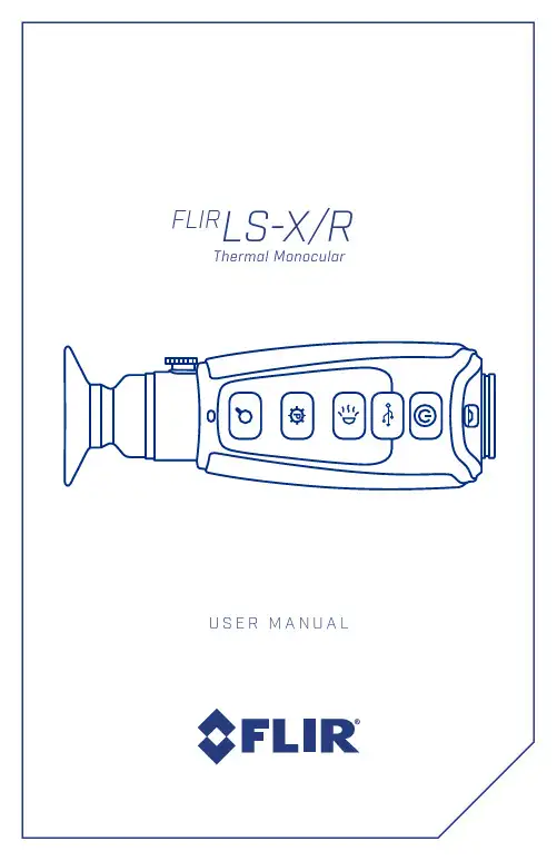
© 2019 FLIR Systems, Inc. All rights reserved worldwide. No parts of this manual, in whole or in part, may be copied, photocopied, translated, or transmitted by any electronic medium or in machine-readable form without the prior written permission of FLIR Systems, Inc.Names and marks appearing on the products herein are either registered trademarks or trademarks of FLIR Outdoor & Tactical Systems and/or its subsidiaries. All other trademarks, trade names, or company names referenced herein are used for identification only and are the property of their respective owners.This product is protected by patents, design patents, patents pending, or design patents pending.If you have questions that are not covered in this manual, or need service, contact FLIR OTS customer support for additional information prior to returning a camera.Phone:1-888-959-2259Email:********************This documentation is subject to change without notice.Proper Disposal of Electrical and Electronic Equipment (EEE)The European Union (EU) has enacted Waste Electrical and Electronic Equipment Directive 2002/96/EC (WEEE), which aimsto prevent EEE waste from arising;to encourage reuse, recycling,and recovery of EEE waste; and topromote environmental responsibility.In accordance with these regulations,all EEE products labeled with the “crossed out wheeled bin” either on the product itself or in the product literature must not be disposedof in regular rubbish bins, mixed with regular household or other commercial waste, or by other regular municipal waste collection means. Instead, and in order to prevent possible harm to the environment or human health, all EEE products (including any cables that came with the product) should be responsibly discarded or recycled.To identify a responsible disposal method where you live, please contact your local waste collection or recycling service, your original place of purchase or product supplier, or the responsible government authority in your area. Business users should contact their supplier or refer to their purchase contract.FLIR LS-X/R U S E R M A N U A LImportant Instructions and Notices to the User: Modification of this device without the express authorization of FLIR Systems, Inc. may void the user’s authority under FCC rules to operate this device.Note 1: This equipment has been testedand found to comply with the limits for a Class B digital device, pursuant to Part 15 of the FCC rules. These limits are designed to provide reasonable protection against harmful interference in a residential installation.This equipment generates, uses, and can radiate radio frequency energy and, if not installed and used in accordance with the instructions, may cause harmful interferenceto radio communications. However, there is no guarantee that the interference will not occur in a particular installation. If this equipment does cause harmful interference to radio or television reception, which can be determined by turning the equipment off and on, the user is encouraged to try to correct the interference by one or more of the following measures:• Reorient or relocate the receiving antenna • Increase the separation between the equipment and receiver• Connect the equipment into an outlet on a circuit different from that of the receiver • Consult the dealer or an experienced radio/ television technician for help.Industry Canada Notice:This Class B digital apparatus complies with Canadian ICES-003.Avis d’Industrie Canada:Cet appareil numérique de la classe B est conforme à la normeNMB-003 du CanadaFLIR Systems, Inc.9 Townsend WestNashua, NH 03063Phone: 1-888-959-2259or (603) 324-7600Fax: 1-888-959-2260E-mail:********************Export InformationEquipment described herein may require US Government authorization for export purposes. Diversion contrary to US law is prohibited.©2020 FLIR Systems, Inc.Specifications are subject to change without notice, check our website:3CONTENT Page1. Introduction52. Getting Started73. Operating the System94. Symbology135. Maintenance146. Warranty147. Specifications15 FLIR LS-X/R U S E R M A N U A L1.1 SCOPEThis manual covers the FLIR LS-X/R Series and all applicable components. It is recommended that you read and understand this manual to optimize the monocular’s operation.1.2 INTRODUCTIONFLIR’s LS-X/R Series thermal handheld monoculars give hikers, law enforcement professionals and first responders the ability to see clearly in total darkness, providing a wealth of information during any nighttime mission.1.3 FEATURES• Rugged design – built to withstand the demands of outdoor use.• Microbolometer sensor for excellent image quality and clarity• Palm-sized portability and lightweight – only 12 ounces• Red laser pointer• Battery charging via USB cable• USB/Video adapter cable for video out• Rechargeable internal li-ion battery – provides up to 5 hours of camera operation on a single chargege 1.4 REGISTER YOUR LS-X/RIn order to validate the warranty on your product, FLIRl Systems Inc. must register the product on https:///support-center/support-hq/5FLIRLS-X/R U S E R M A N U A L1.5 INFRARED THERMAL VISION VERSUS IMAGE INTENSIFIED NIGHT VISIONThe FLIR LS-X/R makes images from heat, not light, a feat impossible for the naked eye or image intensified (I 2) night vision devices. This allows you to see clearly without any visible light. People, animals, and objects all generate or reflect heat and are clearly seen by the FLIR LS-X/R in even the most adverse conditions.FLIR LS-X/R ENABLES THEOUTDOOR ENTHUSIAST TO:•See animals and difficult terrain in reduced visibility or total darkness• See through smoke, dust, and light fog • See camouflage and foliage in any lighting conditions•See more – and see farther – than with low-light night vision gogglesIMAGE INTENSIFIED I2THERMAL IMAGING1.6 DETECTION, RECOGNITION, IDENTIFICATIONDETECTION I see something.RECOGNITIONIt’s a four-legged animal.IDENTIFICATION I can tell it is an Elk.72.1 UNPACKING AND INSPECTINGThe FLIR LS-X/R Series monocular is available with the features, options, and accessories described in this manual. Refer to the packing list enclosed with your product to determine the actual contents of your product package.In addition to the product the following items are included in the product package:• FCC Declaration of Conformity • CE Declaration of ConformityQuick Start Guide Wrist Strap Lens CapUSB to RCA Cable(320 & 640 models only)USB CableUSB Power AdapterMolle-CompatibleBelt HolsterFLIRLS-X/R U S E R M A N U A L2.2 CHARGING THE SYSTEMTo assure proper charging, LS-X/R Series monoculars should be turned OFF throughout the charging cycle. Charging MUST only be done when the camera temperature is from 0 to 40°C (32 to 104°F), or battery damage may occur.The monocular battery should be fully charged prior to use. To charge the monocular, lift the cover from the USB port, plug in the USB cable provided with the monocular, and plug other cable end into a USB power source.• When charging the charging indicator will be lit orange.• When fully charged, the charging indicator will light solid green. The initial charge time is approximately 5 hours.2.3 BATTERYYour LS-X/R Series monocular is equipped with a sophisticated power system that uses a rechargeable internal Li-Ion battery.BATTERY STATUS INDICATORWhile the monocular is ON, a battery status indicator is always shown in the corner of the display image. This indicator provides an estimation of the remaining battery charge.BATTERY SAFETY INFORMATIONThe LS-X/R Series monocular is a sealed unit with sensitive electronics and contains no user-serviceable parts. Service or repairis to be performed only by the manufacturer. The monocular must never be opened or modified by the user. The monocular contains no user serviceable components. The battery used in this device may present a risk of fire or chemical burn if mistreated. Do not disassemble the monocular, store above 60°C, or incinerate. The battery is replaceable only in the factory. Return the product to the manufacturer for battery replacement.Full Charge Half Charge Plugged In93.1 SYSTEM CONTROLS AND BUTTONS3.1.3 DISPLAY BRIGHTNESSBUTTONUse this button to cycle through the five levels of display brightness. Each press of the button advances to the next level of brightness.When the highest brightness level is reached, subsequent button presses advance to the next lower brightness levels. When the lowest brightness level is reached, subsequent button presses advance to the next higher brightness level. One of the following icons is displayed for approximately 3 seconds after the button ispressed indicating the current brightness level:3.1.1 DIOPTER ADJUSTMENTWhile looking through the eyepiece, adjust the position of the diopter lever to optimize the sharpness of the image in the viewfinder.3.1.2 POWER BUTTONThe Power Button performs thefollowing functions:FLIRLS-X/R U S E R M A N U A L3.1.4 COLOR PALETTESUse this button to toggle between the available color palettes. Please see the following images forexamples of LS-X/R’s color palettes.WHITE HOTMost commonly used palette. Hot objects appear white. Good for scenes with either highor low contrast.BLACK HOTHot objects appear black. Scenes appear more lifelike than White-Hot, especially at night.INSTALERT ™ LEVEL 1The hottest 5% of things in the image arecolored and everything else is greyscale.INSTALERT ™ LEVEL 2The hottest 10% of things in the image are colored and everything else is greyscale.INSTALERT ™ LEVEL 3The hottest 15% of things in the image are colored and everything else is greyscale.INSTALERT ™ LEVEL 4The hottest 20% of things in the image arecolored and everything else is greyscale.113.1.5 ZOOM BUTTONUse this button to switch the monocular between no zoom (full resolution), 2X and 4X (LS-X), and 2X, 4X, and 8X (LS-XR). The central part of the image is magnified by the zoom level selected.When zoom has been selected, the icon appears continuously in the display. See user menu section for additional details3.2 USING USB/ANALOG VIDEO ADAPTER CABLETo obtain analog video out, insert the adapter cable into the USB connector. The monocular will detect the adapter cable and provide the video stream. Use an RCA cable to connect to a monitor or a video recorder.When using the USB/Analog Video Adapter cable to record video or supply video to a remote monitor, it may be useful to turn off the Auto Power Off feature of the monocular. Set the video format using the LS-X/R/LS-X/LS-XR End User Tool.3.3 LS-X/R POWER MANAGEMENTYour LS-X/R Series monocular is equipped with a power management system that provides up to five hours of continuous operation. When left in the Off state the battery will hold a charge for up to two months. To use the product it is important to understand the basic power states of the product.• When the monocular is turned on from the Off state, it takes about five seconds to become operational. During the boot up process, the FLIR splash screen is shown. Pressing the Power button will toggle the monocular between On and Off.• The camera shuts down after about five minutes if no buttons are pushed.3.4 AUTO POWER OFF OPERATIONAuto Power Off is a feature of the LS-X/R Series monocular that helps to guard against draining the battery prematurely by inadvertently leaving the camera on.Auto Shutdown turns the camera off if the following conditions are met:• The product is On• No buttons have been pressed for five minutesOnce these conditions are met, you will see the following message in the display: “Auto Power Off 30s.” After counting down for 30 seconds, the monocular will shutdown.Press any button during this countdown to terminate Auto Power Off and resume normaloperation.3.5 AUTO FFC / CALIBRATIONBy design, the camera will periodically initiate a Flat Field Correction (FFC) cycle, also known as a Non-Uniformity Correction (NUC). A shutter activates inside the camera and provides a target of uniform temperature, allowing the camera to correct for ambient temperature changes and provide the best possible image. Just prior to the FFC, a small green square will appear in the upper left corner of the screen for two seconds. When the FFC occurs, the video image temporarily freezes.3.6 LS-X/R/LS-X/LS-XR END USER TOOLThe SCOUT III/LS-X/LS-XR end user tool is a graphical user interface (GUI) that is used with the following FLIR handheld thermal imaging monoculars:• SCOUT III Series• LS-X/R SeriesTo get detailed information,software downloads, or product support for your LS-X or LS-XR visit the product page at: /support-center/support-hq/FLIR LS-X/R U S E R M A N U A L13The LS-X/R user interface has a clear and simple on-screen symbology that allows the user to easily navigate through the settings, and optimize the image quality based on certain variables. From the zoom function to palette choice the symbology on-screen matches the button symbology so the user becomes instantly familiar with how to manipulate and operate all of LS-X/R’s functions.See the reference points below to get a solid understanding of the onscreen functionality.This symbol clearly identifies the current palette being used. In this example,InstAlert level 1 is displayed (I1).The magnifying glass clearly indicates thezoom functionality of the LS-X/R and the 2X inside the symbol indicates the magnification.The battery symbol clearly displays the battery status.The brightness indicator appears on screen when adjusting the brightnesslevel of the LCD screen.5.1 SOFTWARE UPDATE Software updates for your LS-X/R can befound at:/support-center/support-hq/.5.2 BATTERY SERVICE AND REPLACEMENTIf the battery will not hold a charge and requires replacement, please contact FLIR Systems for details on returning the unit for service.For instructions on charging the battery refer to Section 2.3 Charging the system.5.3 CLEANING THE LS-X/R Wipe the housing with a damp cloth, as needed.Use a high quality lens wipe to remove dirt or smudges from the lens and display window.Do not use abrasives or solvents to clean the housing, lens, or display window.5.4 CAUTIONS• Do not disassemble the monocular enclosure.Disassembly can cause permanent damage.The battery is not user-replaceable• Do not point the monocular at high-intensity radiation sources, such as the sun, lasers, or arc welders• Do not leave fingerprints on the monocular’s infrared optics. Clean only with low pressure fresh water and a lens cloth• All service must be provided by themanufacturer6.1 GLOBAL LIMITED WARRANTY Follow the link to https:///support-center/warranty/ retrieve FLIR’s warranty document.6.2 PRODUCT REGISTRATION In order to validate the warranty on your product, FLIR Outdoor & Tactical Systems must register the product on https:///support-center/support-hq/.6.3 OBTAINING WARRANTYSERVICE9 Townsend West Nashua, NH 03063 Phone: 1-888-959-2259or (603) 324-7600Fax: 1-888-959-2260E-mail:******************** FLIR LS-X/R U S E R M A N U A L15。

用户手册FARPOINT / FAIRVIEW 系列FARPOINT 80FAIRVIEW 70FAIRVIEW 55FAIRVIEW 40FARPOINT 70FARPOINT 55FARPOINT 40欢迎惠顾Osprey 。
我们专为您的探险之旅打造最具实用性、耐久性和创新性的携带产品,并以此为豪。
请参阅本用户手册,了解产品功能、使用、保养、客户服务和保修方面的信息。
通用功能1 大面板可上锁拉链开合主仓2 前部双压缩带3 前部双网袋4 加垫顶部和侧面提手5 拉链式后片,可收纳并保护腰带和背带6 可隐藏式背板、背带和腰带,设有拉链式后片 ,可起到保护作用 + 两个内部压缩带可安全地固定包内物品+内部前片拉链网袋材质主体 210D 抗撕裂尼龙千鸟格装饰 600D 包装布底部600D 包装布645132FARPOINT 70男款规格S/M M/L立方英寸 4089 4272 升 67 70 磅 3.75 3.92 公斤 1.71 1.78英寸 26h x 13w x 13d 厘米65h x 33w x 34d负载范围磅 | 9-23公斤FARPOINT 80男款规格 S/M M/L 立方英寸 4637 4882 升 76 80 磅 3.73 3.88 公斤 1.69 1.76 英寸 29h x 15w x 16d 厘米74h x 38w x 40d负载范围磅 | 9-23公斤特有功能1 下部拉链式大储物仓, 带有活动隔层2 顶部拉链式洗漱用具仓3 前面板拉链插袋4 装备外挂点5Daylite 挂环特有功能1 可移除式睡垫固定带2 拉链脱卸式日用背包,设有可上锁拉链主仓 + 笔记本电脑和平板电脑隔层+热压防刮拉链插袋2512FARPOINT 55男款规格 S/M M/L 立方英寸3173 3356 升52 55磅 3.75 3.90公斤 1.69 1.77英寸26h x 13w x 13d厘米65h x 32w x 32d负载范围磅 | 9-23公斤FARPOINT 40男款规格S/M M/L立方英寸2319 2441 升38 40磅 3.11 3.17公斤 1.41 1.44英寸 21h x 14w x 15d厘米 54h x 35w x 37d负载范围磅 | 9-18公斤特有功能1 可移除式睡垫固定带2 拉链脱卸式日用背包,设有可上锁拉链主仓+ 笔记本电脑和平板电脑隔层+ 热压防刮拉链插袋特有功能1 笔记本电脑和平板电脑隔层2 热压防刮拉链插袋3 含肩带2112FAIRVIEW 55女款规格WXS/M WS/M立方英寸 3173 3356 升 52 55 磅 3.76 3.85 公斤 1.71 1.75 英寸 25h x 13w x 12d 厘米63h x 33w x 30d负载范围磅 | 9-23公斤FAIRVIEW 40女款规格WXS/M WS/M 立方英寸 2319 2441 升 38 40 磅 3.09 3.18 公斤 1.40 1.44 英寸 21h x 14w x 13d 厘米54h x 35w x 34d负载范围磅 | 9-18公斤FAIRVIEW 70女款规格WXS/M WS/M立方英寸 4089 4272 升 67 70 磅 3.78 3.87 公斤 1.72 1.76 英寸 25h x 14w x 12d 厘米64h x 35w x 31d负载范围磅 | 9-23公斤特有功能1 可移除式睡垫固定带2 拉链脱卸式日用背包,设有可上锁拉链主仓+ 笔记本电脑和平板电脑隔层+热压防刮拉链插袋11222特有功能1可移除式睡垫固定带2 拉链脱卸式日用背包,设有可上锁拉链主仓 + 笔记本电脑和平板电脑隔层+热压防刮拉链插袋特有功能1 笔记本电脑和平板电脑隔层2 热压防刮拉链插袋3含肩带13背负系统11 LIGHTWIRE TM 框架背负系统+ 3.5 mm LightWire™外围框架有效地将负载从背带传递至腰带+ A tilon撑片将整个背板上的负载分散到外围框架+ 负载调节带将重量从背带传递至腰带2 可隐藏式反向SPACERMESH隔离网垫背板、背带和腰带+ 光滑的网面Atilon泡沫提供了与负载支撑核心舒适、透气的接触面尺寸/贴合度隐藏式背带/腰带隐藏式背带/腰带FAIRVIEW - 女款尺寸WXS/S 13-17" / 33-43 cmWS/M 16-20" / 41-51 cm背带贴合度背带应完全包覆肩部,背包与您的背部之间不应有空隙。


Dual Use: Shooting Tactical / Hunting Patent PendingPRISM SCOPE SPITFIRE ™T he S piTfire3x p riSm S cope The perfect choice for the AR platform, the Spitfire ™ 3x prism scope combines a compact, prism-based design with the intuitive glass-etched EBR-556B reticle—providing vital speed, accuracy and versatility in close to medium range shooting scenarios.Picatinny RailWindageAdjustmentElevation AdjustmentBattery CompartmentLens— Please read entire manual before using your new optic.Ocular Lensc onTrolS and a djuSTmenTSBattery InstallationRemove the battery compartment cover usinga coin or screwdriver. Install and orient theCR 2032 battery so the positive side (+) facesupward, then replace the cover. When replacingthe cover, be sure it is fully screwed down withthe o-ring seal in place.Illumination ControlThe reticle can be used without illumination.To activate the reticle illumination, rotate theillumination dial to the left or right. The dial shows both red and green numbers, indicating five levels of brightness. Rotate the dial so the number indicating the desired color and intensity faces the shooter.Note: Be sure to turn the dial to zero when done shooting to avoid running the battery down prematurely.Rotate dial to set the preferred color andintensity.SPITFIRE™p riSm S cope a djuSTmenTSReticle FocusThis Spitfire prism scope uses a fast focus eyepiece designed to quickly and easily provide a sharply focused reticle. Array To adjust the reticle focus:• L ook through the scope at a blankwhite wall or up at the sky.out until the reticle image is as crispas possible.• N ote: Try to make this particularadjustment quickly, as the eye will tryto compensate for an out-of-focus reticle.Once this adjustment is complete, it will not be necessaryto re-focus every time you use the scope. However, because your eyesight may change over time, you should re-check this adjustment periodically.WarningLooking directly at the sun through a scope, or any opticalinstrument, can cause severe and permanent damage to youreyesight.Windage and Elevation AdjustmentsThe Spitfire incorporates elevation and windage dials with audible clicks. Each small click will move the point of impact 1/2 Minute of Angle (MOA). 1/2 MOA will closely correspond to 1/8 inch at 25 yards, 1/4 inch at 50 yards, 1/2 inch at 100 yards and 1 inch at 200 yards.Adjust the settings• R emove the dial covers.• U se a coin or screwdriver to make the adjustments.• T urn the adjustment dial in the appropriate direction asindicated by the arrows. Move the dials in the direction you wish the bullet’s point-of-impact to change.ExampleAt a 50 yard sight-in distance, it will take four clicks of the dial to move the bullet’s point-of-impact one inch.Elevation Windage Rotate the adjustment dial in the direction you wish the bullet’s point-of-impact to change. For example, turning the turret counter-clockwise will move thepoint-of-impact up or to the right.PRISM SCOPE SPITFIRE ™Mounting the SpitfireOrient the Spitfire so the illumination dial faces shooter.1. Loosenthe two baseclamp hex nutsand attachthe Spitfireto the rail/base, makingsure that recoillugs are solidlyseated in basegrooves.2. Checking that the mount fully engages the base, press the Spitfire downand forward, then tighten and torque the base clamp hex nuts. Note: To prevent recoil injury, position it so that you have at least two inches of eye relief once the Spitfire scope is attached. Be sure you can see the full field of view through the scope before tightening down the mount.Recommended TorqueBase Clamp Hex Nuts 35–45 in/lbsMount HeightsThe Spitfire comes from the factory with a mounted height of40.4 mm from the optic center to base surface. This is commonly referred to as a lower 1/3 co-witness height. If a lower 30 mm mounted height is desired, loosen the two mount screws then remove the base clamp and mount riser. Remove the mountriser and reinstall the base clamp with the shorter mount screws provided in the box using a non-permanent thread-lockingcompound when installing the screws.Mount RiserBase Clamp Mount Screw Hex NutS ighTing inBore SightingAfter mounting, an initial bore sighting of the Spitfire at short range (25–50 yards) will save time and money at the range. This can be done using a bore sighter according to the manufacturer’s instructions, or by removing the bolt on some rifles and visually sighting through the barrel.To visually bore sight a rifle:1. Place the rifle solidly on a rest and remove the bolt.2. Sight through the bore and center the target inside the barrel.3. With the bull’s eye centered in the bore, make windage and elevation adjustments until the center dot is aligned over the bull’s eye.Final Range Sight-InFinal sight-in should be done at the range using the exact ammunition you expect to hunt or shoot with:4. After the Spitfire has been bore sighted, fire a shot or twoat your desired zero distance to check that you’re roughly on target. If necessary, adjust the dot to put you near the center of the target (see Windage and Elevation Adjustment on page 6).5. Fire a three-shot group as precisely as possible.6. Using the center of this group as a reference, make any necessary adjustments for windage and elevation correction. Using arrows for reference, adjust dials in the direction you wish the group to move.7. Fire a final three-shot group to confirm proper adjustment. Repeat as necessary.SPITFIRE™S hooTing wiTh The S piTfireYour Spitfire 3x scope is equipped with the EBR-556B Enhanced Battle Reticle. Although this precision reticle has been designed around the popular 5.56x45 (.223 Remington) cartridge using a 55 grain bullet and 16-inch barrel, it can also be used effectively with many other cartridges and barrel lengths. Be aware that the more a cartridge varies in bullet drop from the 5.56 round, the greater the difference will be in the referenced yardage numbers. The main crosshair intersection of the EBR-556B reticle is intended to be zeroed at 100 yards (see Sighting In on page 8). Due to the flat trajectory of the 5.56 round, this will allow the central crosshair to be used effectively form 0–200 yards. Note: If you are using the center crosshair at 200 yards, maximum accuracy will be obtained by holding 3-inches (1.5 MOA) high on the desiredtarget.horizontallines belowthe centralcrosshair willthen provide300, 400 and500 holdoverreferences.EBR-556B Reticle Holdover ReferencesRangingThe EBR-556B reticle incorporates a simple ranging design. By matching an object of 15 inches in width (example, theshoulder width on a silhouette target) to the crossbar images, the approximate range can be determined.Ranging Crossbars 15 InchesSubtensions are measured in MOA.a cceSSory o pTionSThe 3x Spitfire includes two Picatinny rails for mounting accessories such as lights, lasers and red dot sights.If desired, rails can beremoved.SPITFIRE™Array PRISM SCOPET roubleShooTingPlease check the following before returning a scope for service: If the reticle does not illuminate:• I s the battery dead? Replace.• I s the battery installed correctly? Be sure the battery is oriented with plus sign facing upward.• I s the battery cover loose? Be sure cover is snug and contact points are clean.If bullets are not grouping:Be sure the crossbolt nut is tight. You should not be able to twist or move the Spitfire in any direction. Many times, problems thought to be with the scope are actually mount problems. Note: For any issues not listed above, please view our online Troubleshooting Guide at /content/troubleshootingm ainTenanceCleaningThe Spitfire prism scope requires very little routine maintenance other than to periodically clean the exterior lenses. The exterior of the scope may be cleaned by wiping with a soft, dry cloth. When cleaning the lenses, be sure to use products that are specifically designed for use on coated optical lenses such as our Lens Pen and FogFree Cleaning Kits.• B e sure to blow away any dust or grit on the lenses prior to wiping the surfaces.• U sing your breath, or a very small amount of water or pure alcohol, can help remove stubborn things like dried water spots.LubricationAll components are permanently lubricated, so no additional lubricant should be applied.Note: Do not attempt to disassemble any components of the scope.StorageKeep lens covers closed to protect the lenses when not in use.• R emove the battery when putting in storage for extended periods.• A void storage in direct sunlight or in any very hot location.• S torage and use in extreme cold will shorten battery life.PRISM SCOPE SPITFIRE ™T he Vip w arranTyWe build optics based on our commitment to your absolute satisfaction. That’s why our products are unconditionallyguaranteed and we make this Very Important Promise to you—a Very Important Person.Rest assured that in the event your Spitfire becomes damaged or defective, we will repair or replace the red dot at no charge to you. Call us at 800-426-0048 for prompt, professional, and friendly service.2120 West Greenview DriveMiddleton, WI 53562************************Visit for more information. Canadian customers may visit for customer service information.Note: The VIP Warranty does not cover loss, theft, deliberate damage or cosmetic damage that does not hinder the performance of the product.Lifetime WarrantyUnlimited Unconditionalmon_spitfire-3x_2016_V1/S。
MANUAL DE OPERACIONESEste símbolo tiene el propósito, de alertar al usuario de la presencia de “(voltaje) peligroso” sin aislamiento dentro de la caja del producto y que puede tenerUna magnitud suficiente como para constituir riesgo de descarga eléctrica.Este símbolo tiene el propósito de alertar al usario de la presencia de instrucciones importantes sobre la operación y mantenimiento en la información queviene con el producto.PRECAUCION: Riesgo de descarga eléctrica ¡NO ABRIR!PRECAUCION: Para disminuír el riesgo de descarga eléctrica, no abra la cubierta. No hay piezas útiles dentro. Deje todo mantenimiento en manos delpersonal técnico cualificado.ADVERTENCIA: Para prevenir choque electrico o riesgo de incendios, este aparato no se debe exponer a la lluvia o a la humedad. Los objetos llenos deliquidos, como los floreros, no se deben colocar encima de este aparato. Antes de usar este aparato, lea la guia de funcionamiento para otras advertencias.Terminal de puesta a tierra de protección. El aparato debe estar conectado a una toma de corriente con conexión a tierra de protección.INSTRUCCIONES IMPORTANTES PARA SU SEGURIDADCUIDADO: Cuando use productos electrónicos, debe tomar precauciones básicas, incluyendo las siguientes:1. Lea estas instrucciones.2. Guarde estas instrucciones.3. Haga caso de todos los consejos.4. Siga todas las instrucciones.5. No usar este aparato cerca del agua.6. Limpiar solamente con una tela seca.7. No bloquear ninguna de las salidas de ventilación. Instalar de acuerdo a las instrucciones del fabricante.8. No instalar cerca de ninguna fuente de calor como radiadores, estufas, hornos u otros aparatos (incluyendo amplificadores) queproduzcan calor.9. No retire la patilla protectora del enchufe polarizado o de tipo “a Tierra”. Un enchufe polarizado tiene dos puntas, una de ellasmás ancha que la otra. Un enchufe de tipo “a Tierra” tiene dos puntas y una tercera “a Tierra”. La punta ancha (la tercera ) seproporciona para su seguridad. Si el enchufe proporcionado no encaja en su enchufe de red, consulte a un electricista paraque reemplaze su enchufe obsoleto.10. Proteja el cable de alimentación para que no sea pisado o pinchado, particularmente en los enchufes, huecos, y los puntos quesalen del aparato.11. Usar solamente añadidos/accesorios proporcionados por el fabricante.12. Usar solamente un carro, pie, trípode, o soporte especificado por el fabricante, o vendido junto al aparato. Cuando se useun carro, tenga cuidado al mover el conjunto carro/aparato para evitar que se dañe en un vuelco. No suspenda esta caja deninguna manera.13. Desenchufe este aparato durante tormentas o cuando no sea usado durante largos periodos de tiempo.14. Para cualquier reparación, acuda a personal de servicio cualificado. Se requieren reparaciones cuando el aparato hasido dañado de alguna manera, como cuando el cable de alimentación o el enchufe se han dañado, algún líquido ha sidoderramado o algún objeto ha caído dentro del aparato, el aparato ha sido expuesto a la lluvia o la humedad, no funciona demanera normal, o ha sufrido una caída.15. Nunca retire la patilla de Tierra.Escríbanos para obtener nuestro folleto gratuito “Shock Hazard and Grounding” (“Peligro deE lectrocución y Toma a Tierra”). Conecte el aparato sólo a una fuente de alimentación del tipo marcado al lado del cable dealimentación.16. Si este producto va a ser enracado con más equipo, use algún tipo de apoyo trasero.17. Nota para el Reino Unido solamente: Si los colores de los cables en el enchufe principal de esta unidad no corresponden conlos terminales en su enchufe‚ proceda de la siguiente manera: a) El cable de color verde y amarillo debe ser conectado alterminal que está marcado con la letr a E‚ el símbolo de Tierra (earth)‚ coloreado en verde o en verde y amarillo. b) El cablecoloreado en azul debe ser conectado al terminal que está marcado con la letra N o el color negro. c) El cable coloreado enmarrón debe ser conectado al terminal que está marcado con la letra L o el color rojo.18. Este aparato eléctrico no debe ser sometido a ningún tipo de goteo o salpicadura y se debe tener cuidado para no ponerobjetos que contengan líquidos, como vasos, sobre el aparato.19. El interruptor de en/lejos en esta unidad no rompe ambos lados de la red primaria. La energía peligrosa puede ser presentedentro del chasis cuando el interruptor de en/lejos está en el de la posición. Eltapón de la red o el acoplador del aparato sonutilizados como el desconecta dispositivo, el desconecta dispositivo se quedaráfácilmente operable.20. La exposición a altos niveles de ruido puede causar una pérdida permanente en la audición. La susceptibilidad a la pérdida deaudición provocada por el ruido varía según la persona, pero casi todo el mundo perderá algo de audición si se expone a unnivel de ruido suficientemante intenso durante un tiempo determinado. El Departamento para la Salud y para la Seguridad delGobierno de los Estados Unidos (OSHA) ha especificado las siguientes exposiciones al ruido permisibles:Duración por Día en Horas Nivel de Sonido dBA, Respuesta Lenta8 906 924 953 972 1001 1⁄2 1021 1051⁄2 1101⁄4 o menos 115De acuerdo al OSHA, cualquier exposición que exceda los límites arriba indicados puede producir algún tipo de pérdida en la audición.Protectores para los canales auditivos o tapones para los oídos deben ser usados cuando se opere con este sistema de sonido para preveniruna pérdida permanente en la audición, si la exposición excede los límites indicados más arriba. Para protegerse de una exposicióna altos niveles de sonido potencialmente peligrosa, se recomienda que todas las personas expuestas a equipamiento capaz de produciraltos niveles de presión sonora, tales como este sistema de amplificación, se encuentren protegidas por protectores auditivos mientras estaunidad esté operando.¡Felicidades! Acaba de comprar el mejor sistema PA portátil del mundo. El diseño integrado del Escort facilita la transportación,al mismo tiempo que sus controles amigables hacen fácil su operación, convirtiéndolo en la elección perfecta para escuelas,iglesias, organizaciones cívicas, DJ y pequeños grupos musicales. El Escort presenta dos altavoces de dos vías accionados por unmezclador amplificado de siete canales, por lo que es ideal para aplicaciones vocales, musicales y de DJ. El mezclador incluye uncanal de medios con varias entradas para múltiples opciones de reproducción, así como funciones de calidad profesional talescomo sección de efectos digitales, anulación de efectos mediante interruptor de pie y ungráfico master de siete bandas conFLS® (Feedback Locating System). La maleta de transportación proporciona almacenamiento adicional para micrófonos, cablesy cualquier accesorio adicional que pueda ser necesario. La maleta del Escort proporciona cierres para el montaje de altavoces,múltiples agarraderas para diferentes opciones de transportación y ruedas para facilitar el transporte. Lea cuidadosamente estasinstrucciones y disfrute de su nuevo Peavey Escora 3000.Sistema de audio portátil profesionalCaracterísticas:• Embalaje cómodo con ruedas estilo equipaje• Sistema de altavoces de dos vías con altavoz de bajos y bocina piezoeléctrica de 10"• Mezclador amplificado de siete canales• Reproducción MP3 USB• Efectos digitales de alta calidad• 6 entradas de combinación XLR – 1/4"• Entradas de medios RCA estéreo, 3,5 mm y USB para su reproducción• EQ gráfico de siete bandas con FLS• Dos plataformas plegables para los altavoces• 2 Cables de 15 pies para altavoces• Compartimientos de almacenamiento para micrófonos, cables, etc.• Anulación de efectos mediante interruptor de pie• Micrófono y cable PV*• Soporte de mezclador** Indica características opcionales. Disponible en ciertos modelosConexión de los micrófonos o de las entradas de líneaEl mezclador amplificado del Escort está diseñado para trabajar con cualquier micrófono balanceado de buena calidad, dinámico o deCondensador, tales como los micrófonos de la serie PVi® de Peavey. Conecte el micrófono al conector de entrada XLR (de tres clavijas) como seMuestra (Fig. 5). Si se están utilizando múltiples micrófonos, conéctelos en el orden en que estarán en el escenario para la facilidad de ajusteDe cada micrófono. Para conectar un dispositivo de nivel de línea, tal como un teclado, use un cable de 1/4" para instrumentos e insértelo enEl centro del conector combinado XLR-1/4", como se muestra (Fig. 6).。
AlphaScreen®SureFire®ALK Total Assay KitsManualAssay Points Catalog #500TGRTALS50010 000TGRTALS10K50 000TGRTALS50KFor Research Use OnlyResearch Reagents for Research Purposes OnlyGeneral Information on the AlphaScreen® SureFire® Total ALK assayThe AlphaScreen® SureFire® Total ALK assay is used to measure endogenous anaplastic lymphoma kinase (ALK) in cellular lysates. The assay is an ideal system for normalizing ALK levels for experiments measuring changes in ALK phosphorylation, and can be applied to primary cells if expression levels are sufficient.This assay eliminates the need for laborious techniques, such as Western blotting or conventional ELISA. It is a homogeneous assay, in that no sample washing steps are required, which allows for minimal handling, short assay times, and robotic operation if desired. The assay utilizes the bead-based Alpha Technology, and requires an Alpha Technology-compatible plate reader.Alpha Technology AlphaScreen® SureFire® Assay PrincipleAlphaScreen® SureFire® technology allows the detection of proteins in cellular lysates in a highly sensitive, quantitative and user friendly assay. In these assays, sandwich antibody complexes, which are only formed in the presence of analyte, are captured by AlphaScreen donor and acceptor beads, bringing them into close proximity. The excitation of the donor bead provokes the release of singlet oxygen molecules that triggers a cascade of energy transfer in the Acceptor beads, resulting in the emission of light at 520-620nm.Kit-Specificity informationThis assay kit contains antibodies which recognize two distinct epitopes on anaplastic lymphoma receptor tyrosine kinase (ALK). The protein detected by this kit corresponds to GenBank Accession NP_004295. ALK is also known as CD246; NBLST3; TFG/ALK.These antibodies recognize ALK of human origin. Other species should be tested on a case-by-case basis.Kit ContentsKit Size500 points10,000 points50,000 pointsLysis buffer (5X) 1 x 10 mL 4 x 60 mL 3 x 400 mL Activation buffer 1 x 2 mL 1 x 60 mL 1 x 300 mL Reaction buffer 1 x 2.6 mL 1 x 45 mL 1 x 225 mL Dilution buffer 1 x 1.5 mL1 x 25 mL2 x 60 mLAssay Control Lysate1 tube to be re-dissolved in 250 µL H 2OStorage conditions upon receiptThe kit buffers e.g. 5X Lysis buffer, Activation buffer and Reaction buffer should be stored at 4°C. DO NOT freeze the kit buffers – the Reaction buffer contains antibodies and freeze/thaw cycles can lead to a loss of activity.Materials Required But Not ProvidedThe AlphaScreen SureFire assay kits are optimized to work with AlphaScreen Protein A general IgG detection beads. These are available separately from PerkinElmer. The AlphaScreen Protein A general IgG detection kits contain a biotinylated rabbit IgG control, which can be used to test the instrument settings and bead performance.ItemSuggested source Catalog # Size Protein A general IgG detection kit(contains the Acceptor and Donor Beads) PerkinElmer Inc. 6760617C 6760617M 6760617R 500 pt 10,000 pt 50,000 pt Proxiplate™-384 Plus, white, shallow well assay platePerkinElmer Inc. 6008280 6008289 50/box 200/box Optiplate™-384 Plus, white, assay plate PerkinElmer Inc. 6007290 6007299 50/box 200/box TopSeal-A 384, clear adhesive sealing film PerkinElmer Inc. 6050185100/boxEnvision® or Enspire® Alpha-readerPerkinElmer Inc.--Buffer preparation and subsequent storage conditions5X Lysis bufferStore 5X Lysis buffer at 4°C. For assay, dilute 5-fold in water immediately prior to use. Discard unused buffer. Activation bufferPrecipitation will occur during storage 4°C. To re-dissolve, warm to 37°C and mix. Alternatively, Activation buffer can be stored at room temperature with no loss in activity.Reaction buffer*Keep on ice while in use. Do not freeze.Once diluted discard unused reaction buffer. AlphaScreen ® Protein A IgG KitStore at 4°C in the dark.Acceptor Mix(Reaction buffer + Activation buffer +AlphaScreen ® Acceptor beads)Immediately prior to use, dilute Activation buffer 5-fold in Reaction buffer (e.g. take 98 μL Activation buffer and dilute in 392 μL Reaction buffer).Dilute Acceptor beads 50-fold in Acceptor mix (e.g. add10 μL Acceptor beads to 490 μL of premixed Reactionbuffer + Activation buffer).The Acceptor mix should be used immediately for best results. Excess mix should be discarded.Donor Mix**(Dilution buffer + AlphaScreen ®Donor beads)Immediately prior to use, dilute Donor beads 20-fold in Dilution buffer (e.g. add 10 μL Don or beads to 190 μLDilution buffer).The Donor mix should be used immediately for best results. Excess mix should be discarded.Assay Control lysateAfter reconstitution in 250 μL water, lysates should be frozen at -20°C in single use aliquots and used within 1 month.* Do not vortex the Reaction buffer, as vigorous mixing can damage some antibodies. ** Prepare and use Donor Mix under low-light conditions.Control Lysate informationControl lysates are prepared from Karpas-299 cells in growth phase (DSMZ #ACC 31), at a concentration of approximately 10 μg/mL. The controls are supplied lyophilized, and should be reconstituted in either dd H 2O or MilliQ® H 2O. Once reconstituted, lysates should be stored frozen in single use aliquots.Control Lysate: Prepared from flasks of untreated Karpas-299 cells. A serial dilution of controllysate in 1X Lysis buffer should form a linear curve when assayed.Total ALK AlphaScreen® SureFire® Assay ProtocolsA. 2-Plate Assay - assay protocol for adherent cellsCell Seeding1. Seed cells (200 μL of cells for 96 well plates, 50 μL for 384 well plates) in tissue culture plates. Incubate at 37°C overnight in serum-containing media.Cell Treatment2. Remove culture media, and stimulate the cells with 50 μL agonists prepared in serum-free media (25 μL for 384-well plates). (If testing antagonists, prior to stimulation remove culture medium and replace with 50 μL serum-free media containing antagonists (25 μL for 384-well plates)). Return cells to 37°C incubator for desired time. 1 hour is often sufficient for signal transduction inhibitors, and 5 minutes for receptor agonists.Note: Peptidic agonists and antagonists can often stick to plastic surfaces. To minimize this effect, dilute in serum-free media containing a suitable carrier protein (e.g. 0.1% IgG free BSA - Jackson Immunoresearch Cat #001-000-161).Lysate Preparation5. To lyse cells, remove medium from wells, and add freshly prepared 1X Lysis Buffer(50-100 μL fora 96 well plate, 25 μL for a 384 well plate). Agitate on a plate shaker (~350 rpm) for 10 minutes at room temperature.6. Take 4 μL of the lysate and transfer to a 384-well Proxiplate™ for assay. (Add 4 μL Control lysates to separate wells if required).SureFire Assay7. Add 5 μL of Acceptor Mix to wells. Seal plate with Topseal-A adhesive film, and incubate for 2 hours at room temperature.8. Add 2 μL of Donor Mix to wells under subdued light. Seal plate with Topseal-A adhesive film, and cover plate with foil. Incubate for 2 hours at room temperature.Note: Longer incubation may give greater sensitivity. Plates can be incubated overnight if required.9. Read plate on an Alpha Technology-compatible plate reader, using standard AlphaScreen settings.B. 1 Plate Assay - assay protocol for non-adherent cells, and for high-throughput applications. Note: the larger volumes required using this assay will result in achieving less assay points per kit. Cell Seeding1. Harvest cells by centrifugation, and re-suspend cells in HBSS at a suitable cell density. We recommend 107cells/mL as a starting point. Seed 4 μL of cells/well into a 384-well culture plate.2. If using test agents/inhibitors, add 2 μL/well of 4X inhibitors prepared in HBSS.Note: Peptidic agonists and antagonists can often stick to plastic surfaces. To minimize this effect, dilute in serum-free media containing a suitable carrier protein (e.g. 0.1% IgG free BSA - Jackson Immunoresearch Cat #001-000-161).3. Return cells to incubator at 37°C for 1-2 hours.Cell Treatment4. Stimulate cells with agonists by addition of 2 μL/well of 4X agonist stock in HBSS containing 0.1% BSA. The final volume in the wells should be 8 μL. (if no antagonists were used in step 2, stimulate the cells with 4 μL/well of 2X agonist, to give a final volume in the wells of 8 μL.)Lysate Preparation5. To lyse the cells, add 2 μL/well 5X Lysis buffer.(Add 10 μL control lysates to separate wells if required)SureFire Assay6. Add 8 μL of Acceptor Mix to wells. Seal plate with Topseal-A adhesive film, and incubate for 2 hours at room temperature.7. Add 3 μL of Donor Mix to wells under subdued light. Seal plate with Topseal-A adhesive film, and cover plate with foil. Incubate for 2 hours at room temperature.Note: Longer incubation may give greater sensitivity. Plates can be incubated overnight if required.8. Read plate on an Alpha Technology-compatible plate reader, using standard AlphaScreen settings.Representative DataFrequently Asked Questions & TroubleshootingFor comprehensive information on assay optimization and troubleshooting, please refer to the following resources:▪ Guide to AlphaScreen® SureFire ® assay optimization ▪ AlphaScreen® SureFire ® user guideTo download these resources, and other related technical information, visit /category/alpha-surefire-kitsFor general information on AlphaScreen® SureFire ® assays, visit Customer CareTo contact the customer care team, please visit /ServiceCallFor more information regarding related AlphaScreen® SureFire® products andprotocols refer to:PerkinElmer web site: TGR BioSciences website: FOR RESEARCH USE ONLY. NOT FOR USE IN DIAGNOSTIC PROCEDURES.This product is not for resale or distribution except by authorized distributors.LIMITED WARRANTY: PerkinElmer, Inc. warrants that, at the time of shipment, the products sold by it are free from defects in material and workmanship and conform to specifications which accompany the product. PerkinElmer Inc. makes no other warranty, express or implied with respect to the products, including any warranty of merchantability or fitness for any particular purpose. Notification of any breach of warranty must be made within 60 days of receipt unless provided in writing by PerkinElmer Inc. No claim shall be honored if the customer fails to notify PerkinElmer Inc. within the period specified. The sole and exclusive remedy of the customer for any liability of PerkinElmer Inc. of any kind including liability based upon warranty (express or implied whether contained herein or elsewhere), strict liability contract or otherwise is limited to the replacement of the goods or the refunds of the invoice price of goods. PerkinElmer Inc. shall not in any case be liable for special, incidental or consequential damages of any kind.。