MAX1000 用户手册
- 格式:doc
- 大小:535.50 KB
- 文档页数:68
文 件 编 号SMX-1000 操作与保养标准书编 制审 核批 准制订日期:2012.08.21 第 1 页 共 15 页1.目的使SMX-1000 X-RAY 设备操作与保养有依据。
2.范围适用SMX-1000设备。
3.开机操作步骤3.1 打开电源转换开关,从"OFF"打到"ON"。
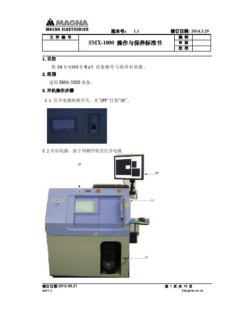
3.2开启电源,按下列顺序依次打开电源文件编号SMX-1000操作与保养标准书编制审核批准3.2.1 打开舱门将设备内部的电源开关从“OFF”打到“ON”。
3.2.2关闭舱门,旋转设备上的电源钥匙开关从“OFF”打到“ON”3.2.3顺时针旋转提起上的紧急停止按钮文件编号SMX-1000操作与保养标准书编制审核批准3.2.4打开计算机电源开关3.2.5打开显示器电源开关文件编号SMX-1000操作与保养标准书编制审核批准3.3 显示器显示软件操作界面,设备自动复位4软件使用4.1设备复位完成后,关闭好设备的舱门。
软件界面显示文件编号SMX-1000操作与保养标准书编制审核批准注意:第一次使用或者停止使用4时后再次使用,系统需要自动预热4.2系统预热完成,软件界面上“Ray”按键显示绿色后打开舱门,将需要测试的产品放入载物台上,关闭舱门,点击软件界面上“抓取主图像”文件编号SMX-1000操作与保养标准书编制审核批准在位置确定之后,点击后,透视的图像就抓取好了。
抓取好之后,调整下方中的亮度、对比度、Gamma数值,使图像达到最清晰的状态。
4.5测量BGA测量对于BGA焊球的气泡比率测量,首先点击BGA文件编号SMX-1000操作与保养标准书编制审核批准点击“Threshold”按钮,会要求对于焊球的尺寸进行设定设定好之后点击“OK”,会要求对测量的范围进行设定文件编号SMX-1000操作与保养标准书编制审核批准选择好范围之后,会要求对焊球进行染色处理,焊球染色结束,在进行气泡的染色文件编号SMX-1000操作与保养标准书编制审核批准染色结束之后,点击“OK”,结束对于测量的设定。

APX1000 QUICKSTART GUIDEENGLISHDo NOT make any connections when any device is powered on.Note: Please see the SPEAKER CONNECTION section for important setup information.QUICKSTART GUIDE (ENGLISH)BOX CONTENTSAPX1000 Power cable Quickstart GuideSafety & Warranty Information BookletQUICK SETUP1. Make sure all items listed in the BOX CONTENTS section are included in the box.2. READ SAFETY & WARRANTY INFORMATION BOOKLET BEFORE USING THE PRODUCT.3. Study the connection diagram in this guide.4. Place all devices in an appropriate position for operation.5. Make sure all devices are turned off and all faders and gain knobs are set to "zero."6. Connect all sound sources' outputs to amplifier inputs as indicated in the diagram.7. Connect the amplifier outputs to speakers.8. Plug all devices into an appropriate power source. 9.Switch everything on in the following order: • Sound sources (i.e. microphones, turntables, CD players, etc.) • Mixer • Amplifier • Speakers10.When turning powering down, turn everything off in the following order: • Speakers • Amplifier • Mixer • Sound sourcesCONNECTION DIAGRAMREAR PANEL DIAGRAM41.COOLING FAN - This fan secures cooling for the amplifier. The airflow is from front to rear. The fan speed is electronically regulated depending on the temperature of the power devices. Do not block these fan grills or mount the amplifier in an enclosed rack, which could cause the amplifier to overheat.2. LOW PASS FILTER – This switch activates the built-in low cut filter. All audio below 30 Hz will be removed from the output signal.3. BALANCED COMBO INPUTS – Connect your mixer to the balancedXLR or balanced 1/4" input for that channel.4.OUTPUT MODE SWITCH – The APX 1000 presents three operating modes: Stereo ModeIn this mode, CH 1 and CH 2 operate independently (as a normalstereo amplifier) The CH 1 input signal will be output from the CH 1 output connector, and CH 2 input signal will be output from the CH 2 output connector. Parallel Mono Mode In this mode, CH 1 input signal will be output from the output connectors of both channels.Bridged ModeIn this mode, CH 1 input signal will be output from the bridge-mono output connector. 5.CHANNEL OUTPUTS – Connect your speakers' input jacks to these outputs. • For the binding posts, red is the positive signaland black is the negative signal. Please makesure to respect the speaker polarity when using binding post. Turn off the unit before connecting an audio signal to the binding post to avoid any electric shock! • The SPEAKON outputs are specifically designed to connect to high power speakers. The correct polarityis secured automatically. They prevent shock hazard and they lock-in securely. Please see the SPEAKER CONNECTION section to properly and safely connect your speakers.6.POWER IN – Connect the cable to a standard wall outlet. Be sure the supplied voltage matches the required voltage of the amplifier. Do not connect the amplifier to an outlet that does not match the required voltage; doing so could damage the amplifier.WARNING!: Do not adjust the STEREO/MONO BRIDGE SWITCH when the amplifier is on. WARNING!: Do not allow any wires of adjacent terminals to come in contact with each other. Also, do not connect either positive (red) output to chassis ground.FRONT PANEL DIAGRAM1. POWER SWITCH – Turns the amplifier on/off.2. POWER LED – Illuminates when the amplifier is on.3. LED METERS – Indicates the audio signal level. This LED will light up when the signal at the output is at least -20 dB.4.CLIP – The red "Clip" light indicates the signal is distorting or "clipping," which occurs when the volumeexceeds the amplifier's maximum output. This LED will flash when distortion reaches a level of 0.5%. Consistent clipping can damage your amplifier and speakers. If the signal is regularly clipping, reduce the volume of the amplifier. If it is lit about half the time, the amplifier channel's thermal protection will cause the channel to shut down within a few minutes.5.PROT – The red "Prot" light indicates the output for that channel has turned off to protect your amplifier andspeakers, which can be damaged by excessive volume resulting in clipping. If the meters' red lights are illuminating, decrease the levels of your CHANNEL GAIN knobs. 6. CHANNEL GAIN – This knob controls the channel's output signal.7. COOLING VENTS – These vents help to cool the internal parts of the amplifier when in use. Do not blockthese vents, and keep the vents clean at all times.SPEAKER CONNECTIONSHORT CIRCUIT PROTECTIONOutput short circuit protection protects the output devices of the amplifier from short circuits and stressful loads. If your speaker lines short, the amplifier automatically detects this problem and discontinues operation for that channel. (If one channel's short circuit protection is activated, the other channel will continue to operate normally.) During short circuit protection, the "Clip" and "Protect" LEDs will light simultaneously, and all output from that channel will stop.Short Circuit Protection can often be traced back to the signal output line (i.e., the speaker line). Check the line from the output terminal of the amplifier to the speaker. If this line is still good, check the internal speaker connections and components. (A short circuit can often be traced to a badcable or a bad speaker component and is rarely traced to the amplifier itself.)Bare Wire Connections:When connecting your speakers to the amplifier using bare wires, follow these steps: 1. Unscrew the red and black caps of the binding posts. (Be sure not to completely remove or unscrew the redand black caps.) 2. Strip back the wire insulation 1/2" (13mm). 3. Insert the bare wire into the hole exposed under the binding post cap. 4. After inserting the wire, screw the binding post cap down on the wire.Spade Connector:When connecting your speakers to the amplifier using spade connectors, follow these steps: 1. Unscrew the red and black caps of the binding posts. (Be sure not to completely remove or unscrew the redand black caps.) 2. Insert the spade connectors into the binding posts. 3. Tighten the caps down on the spade connectors.Banana Connectors:When connecting your speakers to the amplifier using banana connectors, follow these steps 1. Be sure that the red and black caps of the binding posts are tightened completely. 2. Insert the banana connectors into the caps of the binding posts. Be sure that the connectors are insertedsecurely.OPERATION IN STEREO MODEThe APX1000 provides three operating modes: stereo mode, parallel (mono) mode and bridged mode, you can decide each specific operating mode according to your actual application circumstance.In STEREO MODE, channel 1 and channel 2 operate independently (as a conventional stereo amplifier). The channel 1 input signal will be output from the channel 1 output connectors, and the channel 2 input signal will be output from the channel 2 output connectors.OPERATION IN PARALLEL MODEIn this mode, the channel 1 input signal will be output from the output connectors of both channels. The channel 2 input jack is not used; the channel 1 and 2 volumes can be adjusted independently. Use the Parallel Mode when you want to drive two speakers with only one input signal keeping separate control of the volume of the two channels. NOTE: Since you are not using the channel 2 input you can use this socket to "daisy-chain" to another amplifier.OPERATION IN BRIDGED MODEIn this mode, the channel 1 input signal will be output from the bridge output connectors. (The 2 binding posts) In this case, use the channel 1 volume control to adjust the volume, keep the volume control of channel 2 turned completely down (counter clockwise). Bridged mode is intended for driving loads with a total impedance of 8 ohms or greater.In Bridge Mode you will combine the power of both channels into one speaker. You will have a large amount of power available so carefully check the power handling of your speaker before operation.RACKMOUNTING TIPS•It is a good idea to mount this in the bottom of a rack frame. Supporting the back of the unit may be necessary for portable or road use. The APX1000 mounts into a standard 19u rackmount.•ALTO amplifiers are well shielded; however, mounting low-level electronics some distance away from power amplifiers is common practice to reduce the possibility of electromagnetic interference into the low levelunits, which may sometimes be unusually susceptible to picking up such interference.•When wiring a rack, it is good installation practice to route all AC wiring along one side of the rack and all audio wiring along the other side to avoid coupling AC-borne interference into the audio.SPECIFICATIONSPOWER SPECIFICATIONS•*******************%THD:4Ohms390W*2•Both channels driven: 8 Ohms 250W*2•Power EIAJ@ 1% THD 4 Ohms 500W*2•Both channels driven: 8 Ohms 270W*2•Bridge Mono Mode: 8 Ohms 1000W*120Hz-20kHz 16 Ohms 520W*1ELECTRICAL SPECIFICATION•INPUT SENSITIVITY: 1.0V•INPUT IMPEDANCE: 10 K ohm unbalanced•FREQUENCY RESPONSE: (at 10dB below rated output power) 20 Hz~25 KHz (+0/-3 dB)•VOLTAGE GAIN: 32 dB•DISTORTION: (SMPTE-1M) <0.5%•S/N ratio:>110 dB•Inrush Current at initial switch on: 5.85A•Inrush Current after power supply interruption: 6.95AGENERAL SPECIFICATIONS•PROTECTIONS: ON/OFF, muting, DC-fault load grounding relay. Internal fault fuses•CONTROLS Front: AC switch•CONTROLS Rear: Low pass filter, mode selector•SIGNAL INDICATORS: 2 green LED CLIP: 2 red LED•POWER INDICATORS: 1 Blue LED PROTECTION: 1 red LED•INPUT CONNECTORS: Balanced combo•OUTPUT: "Touch-proof" binding posts and speak-on jacks DIMENSIONS•(WxLxH) 483mm x 285mm x 88.8mm; 19” x 11.2” x 3.5”WEIGHT•12.1 lb; 5.4kgMANUAL VERSION 1.1。

SmackFace1000 模块用户手册目录1 简介 (5)1.1 SmackFace1000的目标 (5)1.2 SmackFace1000技术特征 (5)1.3 SmackFace1000为面部识别引擎的技术特性 (5)2 SmackFace1000的基本概念 (7)2.1 SmackFace1000 OEM模块的要求 (7)2.1.1 系统要求 (7)2.1.2 关于面部图像的建议 (7)2.2 用户分类(用户模式) (8)2.3 用户登记 (8)3 SmackFace1000的外部结构 (10)3.1 外部结构 (10)3.2 连接计算机 (11)3.3 标准操作 (11)4 如何使用SmackFace1000 OCX (13)4.1 属性 (13)4.1.1 SFMachineCount (13)4.1.2 SFVerifyLevel (13)4.1.3 WorkingOrgMode (13)4.1.4 SFDatabaseDir¹ (14)4.1.5 SFEnrollCount¹ (14)4.1.6 SFManEnrollState¹ (14)4.2 方法 (14)4.2.1 ConnectAll (14)4.2.2 DisconnectAll (15)4.2.3 SearchAvailableMachine (15)4.2.4 ConnectMachine (15)4.2.5 DisconnectMachine (15)4.2.6 GetCommMode (15)4.2.7 GetMachineIdx (16)4.2.8 GetMachineNo (16)4.2.9 SetMachineNo (16)4.2.10 GetIPAddr (16)4.2.11 SetIPAddr (17)4.2.12 GetCaptureMode (17)4.2.13 SetCaptureMode (17)4.2.14 GetBrightness (17)4.2.15 SetBrightness (18)4.2.16 CaptureImage (18)4.2.17 GetImageData (18)4.2.18 SaveImage (18)4.2.19 Display (19)4.2.20 IsFaceImage (19)4.2.21 IsFaceImageFile (19)4.2.22 ExtractFeatureFromDev (20)4.2.23 ExtractFeatureFromFile (20)4.2.24 Match (20)4.2.25 SendWiegand (21)4.2.26 CardReaderOn (21)4.2.27 BuzzerOn (21)4.2.28 LEDCardGreenOn (21)4.2.29 LEDCardRedOn (22)4.2.30 LEDFaceGreenOn (22)4.2.31 LEDFaceRedOn (22)4.2.32 SFAction (23)4.2.33 ManEnrollStart¹ (23)4.2.34 ManEnrollStop¹ (23)4.2.35 ManCapture¹ (23)4.2.36 Enroll¹ (24)4.2.37 OffLineEnroll¹ (24)4.2.38 RegisterItem¹ (25)4.2.39 Delete¹ (25)4.2.40 DeleteAll¹ (25)4.2.41 Verify¹ (25)4.2.42 VerifyFromFile¹ (26)4.2.43 SearchEmptyID¹ (26)4.2.44 GetIDFromCardno¹ (26)4.2.45 GetCardnoFromID¹ (26)4.2.46 GetUserName¹ (27)4.2.47 SetUserName¹ (27)4.2.48 GetUserType¹ (27)4.2.49 GetFeatureFromDB¹ (27)4.2.50 SetFeatureToDB¹ (28)4.2.51 GetLogCount¹ (28)4.2.52 GetLogInfo¹ (28)4.2.53 DeleteAllLog¹ (29)4.3 事件 (29)4.3.1 OnReceiveCardSign (29)4.3.2 OnVerify¹ (29)5 SmackFace1000软件包 (31)5.1 包的组成 (31)5.2 演示程序1(Visual Basic) (32)5.2.1 界面 (32)5.2.2 控制功能 (33)5.2.3 使用 (34)5.3 演示程序2(Visual C++) (36)5.3.1 界面 (36)5.3.2 功能和控制的使用 (37)1简介本手册描述了Smack Face1000,面部识别+ ID卡考勤机和门禁的设计特性。

MAX1000键盘使用说明通过使用CCTV键盘上的数字盘键入所需号码。
如果键入的号码长度比预期的短(例如,比预期的数字少),那么就必须按键确认该号码已经输入结束。
例如:如果CCTV系统使用的最大摄像机号是20,那么选择任何摄像机时,CCTV 系统将总是承认两位数的摄像机号。
若选择19号摄像机,就必须输入下列键:如果要选择1号摄像机,则必需按。
键也可以选择1号摄像机。
在以上情况中,由于键入了所需位数的号码,就不需要再按键。
若摄像机少于十个(例如从0到9),那么按单个数字就可做出选择。
1 用户登录退出模拟键盘的登陆通过用户名密码的形式完成。
连接键盘后,按下F1 //“登陆键”,如图1所示:键盘液晶板显示如下信息:再按F2键,输入密码。
键盘显示屏显示“OK”表示登录成功。
若显示“ERROR”表示错误。
(在输入用户名并回车后,紧接着输入的是密码,就不用再按F2键了)F1键和F2键的位置如下图所示:此时就可以通过摇杆控制监视器上的图像了。
以上操作中的监视器键和摄像机键,具体位置如下图所示:按下F10退出键(显示“LOGOUT”),此用户退出。
2 选择监视器若要改变一台监视器上的当前图像,首先必须选择这个监视器。
键盘登录成功后,先按监视器键,再按进具体的监视器编号,键盘液晶板显示如下信息:先按键,再输入所需监视器号。
例如:监视器6,或者. 监视器6(对于有十个或十个以上监视器的系统来说)。
监视器的描述文本会被CCTV键盘名字代替,例如:也可能出现的是系统操作员的名字,而这都取决于所使用的CCTV系统的配置。
3 选择摄像机首先必须选择一台监视器。
监视器选择成功后开始选择摄像机。
先按摄像机键,再按进摄像机编号,此时键盘液晶板显示如下信息:监视器和摄像机都选择成功后,键盘液晶板显示如下信息:按键,再输入所需摄像机号。
例如:16号摄像机,或者1号摄像机(对于有十个或十个以上摄像机的系统来说)。
监视器不仅显示当前所选摄像机,同时还显示该摄像机的描述文本。


便携式热敏打印机用户手册山东新北洋信息技术股份有限公司声明本手册内容未经同意内容不得随意更改,山东新北洋信息技术股份有限公司(以下简称新北洋)保留在技术、零部件、软件和硬件上改善产品的权利。
用户如果需要与产品有关的进一步信息,可以与新北洋或经销商联系。
本手册的任何章节没有新北洋的书面许可不得以任何形式、通过任何手段进行复制或传送。
版权本手册于2017年印制,版权属于新北洋。
中国印制。
1.0版本。
商标新北洋使用的注册商标是。
警告、注意警告必须遵守,以免伤害人体,损坏设备。
注意给出了打印机操作的重要信息及提示。
新北洋通过下列管理体系认证ISO9001 质量管理体系认证ISO14001环境管理体系认证OHSAS18001职业健康安全管理体系认证IECQ QC 080000有害物质过程管理体系认证联系方式地址:山东省威海市高技区火炬路169号保修、咨询电话:400-618-1368、800-860-1368 传真:+86—631—5656098QQ:4006181368网址:产品通过下列安全认证:安全须知在操作使用打印机之前,请仔细阅读下面的注意事项:1.安全警告警告:不要触摸打印机的撕纸刀。
警告:打印头为发热部件,打印过程中和打印刚结束,不要触摸打印头以及周边部件。
警告:不要触摸打印头表面和连接接插件,以免因静电损坏打印头。
2.注意事项1)打印机应远离水源并避免阳光、强光和热源的直射。
2)不要在高温,湿度大以及污染严重的地方使用和保存打印机。
3)避免将打印机放在有振动和冲击的地方。
4)如果打印机表面表面结露,在露水消除之前不要打开打印机的电源。
5)将打印机的充电器连接到一个适当的接地插座上。
避免与大型电机或其它能够导致电源电压波动的设备使用同一插座。
6)如果较长时间不使用打印机,请拿出打印机的电池。
7)避免水或导电的物质(例如:金属)进入打印机内部,一旦发生,应立即拿出电池。
8)打印机不得在无纸的状态下打印,否则将严重损害打印胶辊和热敏打印头。
多功能同步整流大功率充/放电器操作说明书天空创新科技(深圳)有限公司 2014目 录0103050809101515171920212223242526介绍产品特性警告及安全提示充电器工作流程图充电器操作说明充电器操作流程再生放电电池记忆程序设置系统设置电池电压检测电池电阻检测警告及错误提示充电器操控软件ChargerMaster 的使用说明相关产品及配件参数常用术语保修及售后服务01 ·Ultimate 1000W 非常感谢您购买天空创新科技(深圳)有限公司生产的1000W 平衡充/放电器。
充电器的使用方法很简单,但是像这种先进的自动充电器仍要求使用者对相关方面的知识有所了解。
此操作说明书会帮助您尽快熟悉充电器的功能特性。
因此在使用之前,请务必仔细阅读操作说明书及警告和安全提示。
我们希望这款充电器能给您带来愉悦及成功的使用体验。
SkyRC Ultimate 1000W 采用最新的同步整流技术,与市面上的同类型充电器相比,有许多新的特点及功能。
用户可自行设定充电截止电压数值,还可以链接电脑,通过电脑对充电器继续操作或者升级固件。
除此之外,用户还可以用充电器测试电池电压及电池内阻。
在安全方面,充电有充电电流保护,容量保护,过温保护以及充电时间保护,使用安全系数高。
SkyRC Ultimate 1000W 输出功率1000W ,最大充电电流40A ,可充20节NiMH /NiCad 电池或者8节锂电。
在充锂电时,如选择平衡模式,可直接在充电过程中对锂电电压进行平衡。
用户可用可靠耐用的薄膜按键对充电器进行操作,双风扇散热效果极好,可在最短时间内对充电器进行降温。
请确定在第一次使用充电器之前,您已经仔细阅读说明书,警告及安全提示。
对电池或者充电器错误使用是非常危险的,可能引起火灾及爆炸。
SkyRC Ultimate 介 绍 使用此产品之前,请认真阅读全本说明书,说明书介绍了使用相关信息及操作安全提示。
使用手册目录1.概述1.1简介1.2系统结构闭路电视键盘模拟屏视频切换子机柜串联组合输入/输出子机柜系统控制器应用程序模块1.3设备识别1.4本手册的使用惯例数字范围特别指出2.性能2.1实时时钟(R T C)2.2视频文本输入后文本预置文本2.3灵活的文本(S m a r t e x t T M)2.4隐藏监视器文本2.5监视器的无效2.6动态文本定位2.7黑屏暂停2.8信号源组合2.9使用C C T V键盘访问通道2.10操作员访问系统2.11列入优先的操作员2.12闭路电视键盘暂停功能2.13自动结束2.14远程控制P T Z摄像机、V C R等P T Z摄像机标准设备控制灵活的设备控制2.15摄像机故障检测视频丢失低电平视频高电平视频2.16视频扫描序列防护观光巡扫2.17宏序列2.18系统宏程序库2.19冷启动宏2.20热启动宏2.21通常报警摄像机故障报警P T Z现场故障报警2.22报警显示分组2.23报警栈2.24辅助输出控制3.基本概念3.1M A X-1000®闭路电视监控系统3.2视频矩阵3.3串联选择视频输入45号的实例选择视频输入3号的实例3.4组合预选子机柜组合器子机柜连接子机柜选择视频输入的实例3.5文本插入3.6子机柜定址有30个视频输出通道的系统有40路输出通道的系统有80路输出通道的系统3.7网络和中继中继线路阻塞管理3.8控制设备P T Z摄像机直接驱动P T Z遥控P T Z现场视频录像机直接V C R控制R S-232V C R接口红外V C R接口电视矩阵V C R接口标准设备控制灵活的设备控制4.模拟屏4.1简化操作环境4.2模拟屏的操作4.3模拟屏的配置M P-88模块M P-88主模块M P-88从模块M P-88模块的优点M P-88的配置为M P-88模块分配插槽一个实例4.4模拟屏的编程按钮(外部报警输入)L E D显示器辅助输出控制5.启动5.1M A X-1000®系统环境5.2S E T M A X配置编辑器从M S-D O S运行S E T M A X从M A X-1000®运行S E T M A X5.3S E T M A X主菜单5.4使用编辑器的环境数字输入字母数字输入前缀数字输入数字范围字段范围5.5屏重叠5.6编辑器命令5.7快命令选择快隐藏快拷贝快移动快选择快将快写入临时文件将临时文件写入快打印快5.8文件命令跳转到另一行保存文件装载文件清工作区扩展工作区撤销工作区5.9状态页5.10把你的新配置保存到磁盘5.11返回到M A X-1000®闭路电视监控系统6.系统的使用6.1预置新系统6.2视频输入信号源引用号(R E F)信号源设备类型(T Y P E)信号源设备号(N o)信号源组号(S G)信号源说明文本(D E S C R I P T I O N-T E X T)子机柜I D号(S U B)视频输入号(I N P)旁路的子机柜I D号(C M B)组合器I D号(C I N)网络信号源(N E T-S O U R C E)备用摄像机(A C N)备用摄像机的视窗信号源控制子机柜I D号(C I D)信号源控制子机柜插槽号(C S L)信号源控制子机柜远程P T Z现场号(C S I)有效的信号源控制(--C T R L--)视频信号源锁定控制(C L K)视频信号源禁用标志的默认状态(S D S)预置文本子机柜I D号(P I D)预置文本插槽号(P S L)水平位置(X)垂直位置(Y)动态视频均衡(D E Q)默认的宏设备标志(01--F L G--16)视频故障探测器插槽号(F S L)视频故障启动宏(S T A R T-M A C R O)视频故障结束宏(F I N I S H-M A C R O)6.3视频输出视频输出通道插槽号(S L T)通道设备类型(T Y P E)通道设备号(N o)通道说明文本(D E S R I P T I O N-T E X T)文本插入子机柜I D号(T I D)文本插入子机柜插槽号(T S L)文本插入子机柜显示状态(T D S)文本显示的水平位置(X)文本显示的垂直位置(Y)起动文本行(O E T L)文本显示暂停时间(T/O)默认的电源通视频输入选择(D F T)默认的电源通扫描序列号(S E Q)扫描序列默认模式(S C A N)通道锁定状态(L C R)可访问的信号源组(0---S G---50)报警显示组(1--A G--50)用键盘访问输出通道(1--K B--32)默认的宏设备标志(01--F L G--16)6.4序列表扫描序列默认模式(S C A N)序列类型(T Y P E)扫描序列的信号源组(S G)扫描序列说明文本(D E S C R I P T I O N-T E X T)扫描序列锁定(L O C K)扫描序列停止周期(D W L)摄像机选择输入项(0199)6.5定义闭路电视键盘键盘设备号(K B)键盘说明文本(D E S C R I P T I O N-T E X T)使键盘能够使用(E N B)默认的键盘操作员(D K O)默认的监视器选择(D F M)键盘可闻声状态(A U D)默认的L C D显示方式(L C D)后事件的类型(-T P E-)后事件宏(P O S T-E V E N T-M A C R O)默认的宏设备标志(01--F L G--16)6.6截取键盘键截取键引用号(R E F)截取键名字(D E S C R I P T I O N)键码号(K E Y)键盘I D号(1--K B--32)置换宏序列(K E Y-R E P L A C E M E N T-M A C R O)键释放宏序列(K E Y-R E L E A S E-M A C R O) 6.7键盘操作员操作员引用号(O P R)操作员名字(O P E A T O R-N A M E)操作员优先权码(P R I)键盘暂停时间(K T O)自动结束周期(A S O)键盘I D号(1--K B--32)视频信号源组(0--S G--50)操作员配置特权(O C P)特种访问特权(S A P)特种控制特权(S C P)可访问的报警组(1--A G--50)使用菜单访问视频矩阵(V M A)其他的菜单访问级(M A L)个人识别号(P I N)登录宏序列(S O N-M A C R O)结束宏序列(S O F F-M A C R O)6.8外部报警输入报警引用号(A L M)报警组号(A G)报警说明文本(D E S C R I P T I O N.T E X T)报警模块子机柜I D号(A I D)报警模块子机柜插槽号(A S L)远程P T Z现场摄像机号(C A M)报警模块输入号(1--I P--8)报警正常状态,正常地锁定/打开(A N S)报警输入操作方式(M O D E)网络报警(N E T-A L A R M)报警禁止状态(A D S)报警启动宏(S T A R T-M A C R O)报警结束宏(F I N I S H-M A C R O)6.9编辑辅助输出控制输出引用号(C/O)输出控制说明(D E S C R I P T I O N)输出模块子机柜I D号(O I D)输出模块子机柜插槽号(O S L)远程P T Z现场的摄像机号(C A M)有效输出位(1--O P--8)网络辅助输出(N E T-A U X)默认的通电输出状态(D F T)6.10系统宏程序库宏引用号(R E F)宏说明文本(D E S C R I P T I O N)宏执行序列(M A C R O-E X E C U T I O N-S E Q U E N C E) 6.11特殊的参数(切记)文本插入行的用法预置文本显示状态系统轮询起动报警栈报警栈暂停视频电平故障打印机制表出错记录制表网络节点I D号主网络时钟时钟校正因子冷启动宏执行序列热启动复位宏执行序列中继阻塞-窃用法则默认的M A X-1000®测试方式6.12串行通讯端口端口号(P O R T)端口类型(T Y P E)说明I D表征码1-8(I D1-I D8)端口地址(A D D R)波特率(B A U D)控制状态(C T R L)6.13显示/清除出错记录文件6.14标题和登记6.15读特许协议6.16从磁盘装载全部数据6.17将全部改变保存到磁盘6.18打印全部配置数据选择打印机类型6.19备份全部配置数据备份的重要性完成磁盘拷贝6.20退出配置编辑器7.实例7.1视频输入固定式摄像机P T Z摄像机伪摄像机摄像机故障探测带有预置文本功能的摄像机网络摄像机视频盒式录像机7.2视频输出有文本的监视器监视器扫描编辑监视器自动黑监视器无文本的监视器网络远程监视器V C R输出通道7.3序列表常规扫描序列锁定的扫描序列保护观光巡扫序列网络扫描序列宏索引表7.4定义C C T V键盘闭路电视键盘1汽车停放K B2控制室3接收哑高级K B系统键盘编辑键盘7.5截取键盘的键选择M O N5解锁(水平左转)自动录像观察周围7.6键盘操作员默认的操作员主管人服务操作员约翰史密斯7.7外部报警输入东部周围休息室的前面(P I R)门接触报警高电平报警模拟屏按钮远程摄像机报警网络报警禁止P T Z篡改7.8辅助输出控制视频打印保持帧门撞锁远程继电器输出吊杆门打开/关闭报警指示器模拟屏L E D显示键盘状态L E D显示高电平状态输出网络辅助输出7.9系统宏程序库检验全门门(第一/第二)只是说明行管理报警监视器报警防区(有效的)报警防区(清除)7.10串行通讯端口键盘端口子机柜端口网络端口高电平端口打印机端口辅助端口出错记录端口测试端口附录A.1宏出错信息A.2宏出错报表A.3键盘键码A.4标准的宏命令A.5运行期错误第一章概述1.1简介M A X-1000®闭路电视(C C T V)监控系统(M A X-1000®C C T V M a n a g e m e n t s y s t e m)是全矩阵视频切换系统。
EnterokinaseMax™ (EKMax™)iiTable of ContentsTable of Contents (iii)Important Information (iv)Methods (1)Overview (1)EKMax™ Digestion (2)Appendix (6)Recipes (6)Technical Service (7)References (8)iiiImportant InformationShipping/Storage EnterokinaseMax™ and the 10X EKMax™ reaction buffer are shipped on blue iceand should be stored at -20°C.Contents EKMax™ in 50 mM potassium phosphate, pH 8.0, 500 mM NaCl and 50%glycerol, is supplied as follows:Catalog no. E180-01:Item AmountVolume EKMax™250 units, 1 unit/µl 250µl10X EKMax™ Reaction Buffer 500 mM Tris-HCl, pH 8.0 (22°C), 10 mM CaCl2, 1% Tween-20 1.5 mlCatalog no. E180-02:Item AmountVolume EKMax™1000 units, 1 unit/µl 1.0 ml10X EKMax™ Reaction Buffer 500 mM Tris-HCl, pH 8.0 (22°C), 10 mM CaCl2, 1% Tween-20 3 x 1.5 mlAdditional Materials Needed You will need to have the following materials:• 37°C water bath or heat block• Deionized water• 1.5 ml microcentrifuge tubes• SDS-PAGE apparatus and buffers (see page 4 for guidelines) • EK-Away™ Resin and buffers (Invitrogen, Catalog no. R180-01) • 15 ml polypropylene tubes (optional)• Chromatography columns (optional, Catalog no. R640-50) • Rocker or rotatorUnit Definition 1 unit is defined as the amount of EKMax™ that will digest 20 µg of BioEase™Mog1 (multicopy suppressor of GSP1, 1)fusion protein to 90% completionin 20 minutes at 37°C in 50 mM Tris-HCl, pH 8.0, 1 mM CaCl2, and0.1% Tween-20 (1X EKMax™ Buffer).For comparison purposes, 1 Invitrogen unit of EKMax™ = ~190 trypsinogenactivation units. Use this conversion only as a rough estimate of how muchEKMax™ to use. It is important to empirically determine the optimal amount ofEKMax™ to digest your fusion protein (see page 2).Limited Label License No. 62: EKMax™Enterokinase This product is sold under patent license from Genetics Institute, Inc. for Research Use Only. Licenses for commercial manufacture or use may be obtained from Genetics Institute, Inc.ivMethodsOverviewIntroduction Enterokinase is a highly specific serine protease that can be used to digest fusion proteins to release the fusion partner or tag from the desired protein. Theenzyme recognizes the sequence -(Asp)4 Lys and cleaves after the lysine residue.This cleavage sequence is present in many expression vectors available fromInvitrogen (contact Technical Service for more information). Genes cloned intothe multiple cloning site of these vectors express recombinant N-terminal fusionproteins. The native proteins can be released from the N-terminal fusion peptideor protein by digesting with enterokinase.EnterokinaseMax™ (EKMax™) is a specially prepared recombinant enzyme,consisting of the catalytic subunit of the holoenzyme. This subunit is expressedand purified from the yeast, Pichia pastoris, yielding an enzyme with higherspecific activity. This results in more efficient cleavage using less enzyme.Description of Enterokinase Enterokinase (enteropeptidase EC 3.4.21.9) is the physiological activator of trypsinogen and a serine protease that exhibits specificity for the sequence (Asp)4 Lys (Anderson et al., 1977). The bovine holoenzyme is a heterodimer consisting of a 115 kDa structural subunit and a 35 kDa catalytic subunit. The larger subunit acts as a membrane anchor and positions the catalytic subunit on the luminal side of the brush border membrane. The catalytic subunit is homologous to other serine proteases and is inhibited by chemical modification of the serine and histidine active site residues (Grant and Hermon-Taylor, 1977; Light and Liepnieks, 1979; Maroux et al., 1971).Specificity of Enterokinase It has been proposed that the active center of enterokinase possesses a distinctive cationic subsite that binds -(Asp)4. Enterokinase is highly specific and tolerates very few changes to its recognition site. If the ionic charge of the recognition site is preserved, enterokinase will recognize the site, but the rate of hydrolysis of the peptide bond will be reduced (Light and Janska, 1989). The four aspartyl residues act as a signal for enterokinase cleavage. It has been reported that with only three aspartyl residues the rate of hydrolysis is reduced. Two aspartyl residues preceding the lysyl residue are the minimum number of acidic residues needed to maintain specificity (Maroux et al., 1971). Non-specific cleavage by enterokinase may occur in the cases described above, but this is usually alleviated by reducing the amount of enzyme used.Expression of the Recombinant Catalytic Subunit EKMax™ is a clone of the catalytic subunit of enterokinase (LaVallie et al., 1993) expressed in the yeast Pichia pastoris. EKMax™ is secreted into the medium, purified, and migrates at 43 kDa on an SDS-PAGE gel. The calculated molecular weight of the protein is 26.3 kDa, but it contains three sites for asparagine-linked glycosylation. The apparent molecular weight of 43 kDa is consistent with previous observations (LaVallie et al., 1993) and is assumed to be because ofN-linked glycosylation.1EKMax™ DigestionIntroduction You will need to have pure or partially pure fusion protein. This sectiondescribes how to digest the fusion protein with EKMax™ to cleave your proteinfrom the fusion partner. This requires setting up a series of pilot reactions todetermine empirically the best conditions for digestion. The efficiency ofcleavage of EKMax™ will differ with each fusion protein. Also, if you areaccustomed to using EK3 (Biozyme), it is still necessary to test differentconcentrations of EKMax™ to determine the right amount for complete digestion.The table below outlines the steps needed to digest your fusion protein andobtain pure protein.Stage Description1 Obtain purified fusion protein at a concentration of > 0.1 mg/ml2 Dialyze (if necessary) into 1X EKMax™ Buffer3 Set up pilot reactions using different amounts of EKMax™ and digestovernight4 Assay reactions on an SDS-PAGE gel and analyze5 Optimize digestion conditions by adjusting amount of enzyme or thetemperature as needed6 Scale-up digestions to produce more of your native protein7 Purify your native protein away from the fusion partner andEKMax™Additional Materials Needed You will need to have the following materials:• 37°C water bath or heat block• Deionized water• 1.5 ml microcentrifuge tubes• SDS-PAGE apparatus and buffers (see page 4 for guidelines) • EK-Away™ Resin and buffers (Invitrogen, Catalog no. R180-01) • 15 ml snap-cap polypropylene tubes (optional)•Chromatography columns (optional, Catalog no. R640-50)• Rocker or rotatorImportantWe have found that EKMax™ will digest fusion proteins bound to theirrespective affinity columns, releasing the desired protein and leaving the fusionpartner bound to the column. For methods to digest Xpress™ fusions bound toProBond™ and thioredoxin fusion proteins in situ on ThioBond™, contactTechnical Service (see page 7).continued on next page2Obtain Purified Fusion Protein Purify at least 120 µg of your fusion protein using your system of choice following the manufacturer's instructions.• To purify thioredoxin fusion proteins, refer to the ThioBond™ manual included with the ThioBond™ resin or contact Invitrogen for information. • To purify Xpress™ fusion proteins, refer to the ProBond™ Purification System manual or contact Invitrogen for informationNote: Both manuals may be downloaded from .EKMax™ will digest fusion proteins in crude cell lysates. Note however, that you will lose your fusion tag and will have to develop a separate protocol for purification of your protein.Dialysis of the Fusion Protein It may be necessary to dialyze your fusion protein against 1X EKMax™ buffer (see Recipes, page 6) before digesting it with EKMax™. EKMax™ is inhibited by high ionic strength. 250 mM NaCl reduces EKMax™ activity to 75% of normal and 2 M NaCl almost completely inhibits enzyme activity (Barratti et al., 1973). Also, EKMax™ is known to be inhibited by > 2 M urea, > 20 mMβ-mercaptoethanol (β-ME), >0.1% SDS, > 50 mM imidazole, and pH values below 6 and above 9.Use the table below to determine if you need to dialyze your fusion protein prior to digestion with EKMax™.If your purified protein ....Then ......contains > 2 M urea, > 250 mM NaCl,> 20 mM -ME, 0.1% SDS, or > 50 mMimidazoledialyze to remove the inhibitorsis in a buffer where the pH is lowerthan 6 or higher than 9dialyze to adjust the pH to between 6and 9.is free from inhibitors and the pH isbetween 6 and 9do not dialyze. Proceed straight toPreparation of Pilot Reactions, below.Recommendation If you are not sure whether you should dialyze your protein or not, dialyze asmall volume of your protein solution and test both dialyzed and undialyzedsamples in a pilot EKMax™ digestion.continued on next page3Preparation of Pilot Reactions You will need at least 120 µg of your fusion protein for the pilot reactions. The ratio of enzyme to fusion protein to achieve complete digestion may vary depending on the protein expressed. It is very important to use only the minimal amount of EKMax™ necessary to completely digest the fusion protein. Excess EKMax™ may cause non-specific cleavage of your fusion protein in some cases.1. To determine the optimal units of EKMax™ needed for complete digestion,use five different amounts of EKMax™ (4 units, 1 unit, 0.1 unit, 0.01 unit,and 0.001 unit). For 4 units of EKMax™, use 4 µl of undiluted EKMax™. Use 1X EKMax™ buffer to make serial 10-fold dilutions of the enzyme.2. Set up 6 reactions, including a reaction without EKMax™ to control forproteases in your protein solution:Fusion Protein 20 µg10X EKMax™ Buffer 3 µlEKMax™1-4 µlDeionized Water to 29 µl(use 30 µl for the no EKMax™ control)Final Volume 30 µl3. Mix well and incubate at 37°C overnight (~16 hours). If your protein isunstable and degrades at 37°C, try incubation at 22°C, 16°C, or +4°C. It is not necessary to increase the time of digestion to compensate for the decrease in temperature.4. Prepare and load 1-20 µl on an SDS-PAGE gel (see next section). For westernblotting, load ~1 µg of your fusion protein, and for Coomassie-stained gels, load ~10 µg.If you wish to digest your fusion protein in a crude lysate, be sure to dialyze toremove any inhibitors of EKMax™. Set up your pilot reactions as described aboveto determine the amount of EKMax™ needed to digest your fusion protein.SDS-PAGEAnalysisUse an SDS-PAGE gel that will allow you to differentiate between undigested anddigested fusion protein. The type of gel and concentration of acrylamide dependson the size of your fusion protein and the fusion partner. Some fusion partners willbe too small to resolve conveniently (i.e. the Xpress™ tag). You should be able todistinguish the removal of the fusion partner from your protein, either byCoomassie-staining or by using antibody detection methods. Choose the dilutionof EKMax™ that gives you complete digestion of your recombinant fusion protein.Recommendationfor ThioredoxinFusion ProteinsA Tricine gradient gel may be necessary to visualize the 14.6 kDa thioredoxinfusion partner (Schagger and von Jagow, 1987). Alternatively, a western blot usingthe Anti-Thio™ Antibody (Catalog no. R920-25) may be used to detect theaccumulation of the thioredoxin fusion partner and/or subsequent loss of signalfrom the native protein.continued on next page4Recommendation for Xpress™Fusion Proteins Since the Xpress™ peptide is less than 4 kDa, a shift in the size of your protein may be undetectable. A western blot using the Anti-Xpress™ Antibody (Catalog no.R910-25) or the Anti-Xpress™-HRP Antibody (Catalog no. R911-25) may be necessary to visualize the cleavage and removal of the Xpress™ fusion peptide from fusion proteins. Perform a western blot and look for the loss of the signal from your protein. The Xpress™ peptide is so small, it may not transfer well to nitrocellulose or nylon, making it difficult to detect.Optimizing EKMax™ Cleavage In some cases, increasing the calcium chloride concentration to 10 mM or the amount of Tween-20 to 1% in the digestion reaction increases the activity of EKMax™. There is a possibility that EKMax™ may recognize sites that are similar to its recognition site; however, the rate of hydrolysis will be reduced. This is usually alleviated by decreasing the amount of EKMax™.Scale-Up of EKMax™ Reaction After you have optimized the EKMax™ reaction, you may scale up your digestion reaction in a linear manner. You may need a concentrated solution of fusion protein in order to scale up your digestion. Use standard ultrafiltration methods to concentrate your protein solution.Removal of EKMax™After digestion, EKMax™ may be removed by affinity chromatography on soybean trypsin inhibitor (STI) resin. For easy removal of EKMax™, EK-Away™Resin (Catalog no. R180-01) is available from Invitrogen. EK-Away™ Resin consists of soybean trypsin inhibitor immobilized on 4% beaded agarose. For a protocol to use EK-Away™ Resin, refer to the EK-Away™ manual. The manual is available at or contacting Technical Service (see page 7).Removal of Fusion Partners Fusion partners may be removed by the same affinity resin as was used to purify the fusion protein. For protocols to remove the Xpress™ tag or the thioredoxin fusion partner after EKMax™ digestion, contact Technical Service (see page 7). For other fusion proteins, consult the manufacturer of your particular system.5Appendix Recipes10X EKMax™Reaction Buffer 500 mM Tris-HCl, pH 8.010 mM CaCl21% Tween-20 (v/v)1. For 1 liter, dissolve 60.5 g Tris base in 950 ml deionized water.2. Adjust pH to 8.0 with concentrated HCl.3. Add 1.47 g CaCl2-2H2O and 10 ml Tween-20 and mix.4. Adjust the volume to 1 liter. Store at room temperature.6Technical ServiceVisit the Invitrogen website at for:• Technical resources, including manuals, vector maps and sequences,application notes, MSDSs, FAQs, formulations, citations, handbooks, etc.• Complete technical service contact information• Access to the Invitrogen Online Catalog• Additional product information and special offersContact Us For more information or technical assistance, call, write, fax, or email. Additional international offices are listed on our website (). Corporate Headquarters:Invitrogen Corporation1600 Faraday AvenueCarlsbad, CA 92008 USATel:176****7200Tel(TollFree):180****6288Fax:176****6500E-mail: ***************************Japanese Headquarters:Invitrogen JapanLOOP-X Bldg. 6F3-9-15, KaiganMinato-ku, Tokyo 108-0022Tel: 81 3 5730 6509Fax: 81 3 5730 6519E-mail: *********************European Headquarters:Invitrogen LtdInchinnan Business Park3 Fountain DrivePaisley PA4 9RF, UKTel: +44 (0) 141 814 6100Tech Fax: +44 (0) 141 814 6117E-mail: ***********************MSDS MSDSs (Material Safety Data Sheets) are available on our website at/msds.Limited Warranty Invitrogen is committed to providing our customers with high-quality goods and services. Our goal is to ensure that every customer is 100% satisfied with ourproducts and our service. If you should have any questions or concerns about anInvitrogen product or service, contact our Technical Service Representatives.Invitrogen warrants that all of its products will perform according tospecifications stated on the certificate of analysis. The company will replace, freeof charge, any product that does not meet those specifications. This warrantylimits Invitrogen Corporation’s liability only to the cost of the product. Nowarranty is granted for products beyond their listed expiration date. No warrantyis applicable unless all product components are stored in accordance withinstructions. Invitrogen reserves the right to select the method(s) used to analyze aproduct unless Invitrogen agrees to a specified method in writing prior toacceptance of the order.Invitrogen makes every effort to ensure the accuracy of its publications, butrealizes that the occasional typographical or other error is inevitable. ThereforeInvitrogen makes no warranty of any kind regarding the contents of anypublications or documentation. If you discover an error in any of our publications,please report it to our Technical Service Representatives.Invitrogen assumes no responsibility or liability for any special, incidental,indirect or consequential loss or damage whatsoever. The above limitedwarranty is sole and exclusive. No other warranty is made, whether expressedor implied, including any warranty of merchantability or fitness for a particularpurpose.continued on next pageReferencesAnderson, L. E., Walsh, K. A., and Neurath, H. (1977). Bovine Enterokinase. Purification, Specificity, and Some Molecular Properties. Biochemistry 16, 3354-3360.Barratti, J., Maroux, S., and Louvard, D. (1973). Effect of Ionic Strength and Calcium Ions on the Activation of Trypsinogen by Enterokinase. A Modified Test for the Quantitative Evaluation of the Enzyme. Biochem. Biophys. ACTA 321, 632-638.Grant, D. A. W., and Hermon-Taylor, J. (1977). Hydrolysis of Artificial Substrates by Enterokinase and Trypsin and the Development of a Sensitive Specific Assay for Enterokinase in Serum. Biochem J. 155, 243-254.LaVallie, E. R., Rehemtulla, A., Racie, L. A., Diblasio, E. A., Ferenz, C., Grant, K. L., Light, A., and McCoy, J. M. (1993). Cloning and Functional Expression of a cDNA Encoding the Catalytic Subunit of Bovine Enterokinase. J. Biol. Chem. 268, 23311-23317.Light, A., and Janska, H. (1989). Enterokinase (enteropeptidase): Comparative Aspects. TIBS 14, 110-112. Light, A., and Liepnieks, J. J. (1979). The Preparation and Purification of Bovine Enterokinase. J. Biol.Chem. 254, 1677-1683.Maroux, S., Baratti, J., and Desnuelle, P. (1971). Purification and Specificity of Porcine Enterokinase. J.Biol. Chem. 246, 5031-5039.Schagger, H., and von Jagow, G. (1987). Tricine-Sodium dodecyl sulfate-Polyacrylamide Gel Electrophoresis for the Separation of Proteins in the Range from 1 to 100 kDa. Anal. Biochem. 166, 368-379.©1998-2006 Invitrogen Corporation. All rights reserved.For research use only. Not intended for any animal or human therapeutic or diagnostic use.。
MAX-1000 矩阵系统用户手册HONEYWELL Co,. Ltd.目录1.综述1.1 简介1.2 CCTV键盘1.3 模拟操作面板1.4 其它设备1.5 本手册所作的前提假定1.6 本手册所用的惯例击键数字范围注意要点监示器信息1.7 厂商联络方式1.8 商标注明2 启动2.1 输入你的选择号码,怎样和为什么?2.2 监示器选择2.3 摄像机选择2.4 PTZ摄像机控制2.5 VCR选择2.6 CCTV键盘控制VCR2.7 摄像机录像2.8 辅助装置和复用器3 扫描序列的使用3.1 什么是扫描序列?什么是扫描序列3.2 启动扫描序列3.3 中止扫描序列3.4 暂停扫描序列3.5 产生新的扫描序列3.6 扫描序列的编辑用新的摄像机选择进行替换删除该摄像机选择插入新的摄像机选择3.7 改变停顿周期3.8 为一个摄像机增加停顿4 宏语言的使用4.1 什么是宏程序?齐投摄像机选择摄像机漫游自动控制4.2 宏语言的执行4.3 产生一个新的宏程序4.4 宏程序的删除4.5 我能编辑一个宏程序吗?5 警报管理5.1 什么是警报?5.2 外部警报输入5.3 摄像机故障警报视频丢失低电平视频5.4 PTZ解码箱故障警报5.5 PTZ解码箱防拆警报5.6 VCR警报5.7 其它装置警报5.8 警报堆栈5.9 在警报堆栈上移位5.10 清除警报6 键盘的其它功能6.1 快速摄像机选择6.2 设置摄像机视场(PTZ预置位) 6.3 调用摄像机视场(PTZ预置位) 6.4 摄像机PTZ复位6.5 选择代用摄像机6.6 隐藏显示的字符6.7 显示SMARTEXTTM7 菜单系统7.1 什么是菜单系统?访问菜单系统退出菜单系统7.2 从菜单上选择移动菜单进入窗口7.3 键盘操作员登记7.4 键盘操作员注销7.5 激活/中止视频输入中止一个摄像机激活一个摄像机7.6 锁定/释放视频输入控制锁定一个PTZ摄像机释放一个PTZ摄像机锁定/释放一个PTZ摄像机7.7 锁定/释放视频输出选项锁定视频输出选项释放视频输出选项锁定/释放视频输出选项7.8 中止/激活警报输入中止警报输入激活警报输入9.3 字符显示定时9.4 监示器黑屏9.5 黑屏暂停9.6 监示器访问9.7 操作员对系统的访问9.8 操作员的级别划分9.9 CCTV键盘定时9.1 0 自动注销9.11 摄像机故障检测视频丢失低电平视频1 0 排除提示10.1 摄像机选择第一章概述1.1简介MAX一1000 CCTV管理系统是一个强功能的计算机控制视频切换矩阵。
操作员可以用CCTV键盘选择不同的摄像机在不同的视频监示器上显示。
对有PTZ控制的摄像机,操作员可以通过CCTV键盘上的操纵杆和其它键对其进行遥控。
录像机,活动探测器和其它视频处理设备全部都可以并入该CCTV系统,并通过CCTV键盘遥控。
外部警报输入可以由程序设定来自动选择摄像机及其它CCTV设备。
该系统还可以检测摄像机有效视频信号电平。
一旦摄像机发生故障,CCTV系统能自动响应,并记录故障。
CCTV系统的外部设备也能用辅助控制输出电路来控制,例如电子门锁或道闸控制全可以通过CCTV键盘控制,MAX一1000 CCTV管理系统的设计能满足大量不同的应用,包括你自己所需要的特定系统。
1.2 CCTV键盘操作员可以通过CCTV键盘以及字符信息显示在监示器上来控制MAX—l000 CCTV管理系统。
根据CCTV系统的大小,系统可以连接多达32个CCTV键盘。
它们能同时并相互独立地对系统进行操作。
有两种键盘:1.RD-500标准CCTV键盘。
2.RD-530增强型CCTV键盘1.3模拟操作面板模拟操作板的主要目的是为了使操作环境尽可能的简单,并给操作者传达尽可能多的信息。
在每一个保安监控系统中,随时了解系统状态是非常关键的,模拟操作板正是为这个目地而设计的。
它们可提示大量信息,易于操作,能最大限度地降低人为错误,最大地提高系统操作员的效率。
在典型的保安系统中,模拟操作板可以显示所有警报区域的当前状态模拟操作板也有按钮,用来对每种相应的警报执行适当的响应,对于楼宇系统,它可以选择正确的摄像机来观察检测警报的区域。
通常,在模拟操作板上画有系统分布图,也可以按区域(或范围)分解,在模拟操作板的每个区域里,LED指示灯和按钮用来指示或执行从警报到摄像机选择的响应。
系统状态可以通过模拟操作板上的LED指示灯表示,LED指示灯可显示警报,也可用来表示你的监示器当前正在显示的区域或摄像机。
它们也可以根据需要按程序执行一个任务,例如,开启一个VCR录像。
模拟操作板上用LED代表警报信号,灯亮即通知系统操作员有警报信号。
系统操作员只需要按下相同区域内的摄像机选择按钮,就可以看到该区域图象。
模拟操作板上的LED指示灯和按钮为系统操作员提供了功能强劲而又简单易懂,操作方便的操作环境。
1.4其它设备MAX-1000CCTV管理系统,综合了多种机箱插板来实现视频切换和整个系统的控制。
在每个系统中所用的设备实际情况有很大差异,难以在本手册中尽述。
你的系统可能包括:口视频切换卡口后置字符叠加卡口固定(不能动)摄像机口PTZ(可动)摄像机口带预制视场的PTZ摄像机口VGR和PTZ控制输出卡口外部警报输入卡口不同的机箱(包括卡)电源和控制计算机口CCTV键盘1.5该手册所作的假设前提为了讨论MAX一1000 CCTV管理系统的操作,我们假设你的系统至少有口l × CCTV键盘口至少在一个视频显示监示器上有后置字符叠加1.6本手册所用的惯例本手册尽可能用插图和范例来帮助你理解某些重点。
击键:CCTV键盘上键钮,由以下标识符来表示:口如表示“0” 键口或表示"ALARM CLEAR"键数值范围:CCTV系统含有多路视频输入和输出选项。
如插图,我们用括号中的=>用来表示数值选择的范围。
口如(01 99)表示允许数值范围从01到99。
注意要点,你应该注意的要点段落将用阴影部分突出击键,这种段落也有图标提示你应注意段落像这样有阴影部分。
在CCTV系统中有些部分(控制摄像机监示器等)是受限于.些操作者,这样的区域虽然在本手册中讨论,但在这之前有提示信息。
对一些操作员拒绝访问监示器信息每个监示器在其自已的字符信息窗口都可以显示当前时间日期,摄像机说明和操作员姓名,这些参数在建立系统配置时就应该定义。
除此以外,警报情况和系统状态等其它信息也会显示,这些特定信息也将出现在字符信息窗口,通常显示在常规字符信息上面。
这些特定信息在本手册中将以下列图标提示:1.7联络方式如果你在使用MAX—l000 CCTV管理系统时遇到困难或者可能有一些有用的信息需要反馈给我们,请与当地的分销商联系。
1.8认可MS-DOS○R Microsoft公司的注册商标MAX-1000TM Maxpro Systems Pty.Ltd的商标SMARTEXT TM Maxpro Systems Pty.Ltd的商标FLASHBACK TM Maxpro Systems Pty.Ltd的商标MAXPRO SYSTEMS TM AND FACE LOGO Maxpro Systems Pty.Ltd的商标Maxpro systems Pty Ltd.已申请了国际专利,含盖了MAX-1000 CCTV系统的特点和概念。
第二章系统启动2.1如何键入你选定的号码。
怎样操作和为什么?对于本手册中讨论的所有CCTV键盘,都必须输入一个相应数值。
例如,选择一个摄像机或者为一条扫描序列设定间隔等。
所需的数字用CCTV键盘上,SELECTION PAD来代表,当输入的数比要求的短(即比要求的位数少)时,必须按回车键说明输入的数已经完成。
举例:如果CCTV系统中用到的摄像机最大数目,举一个例子是20号摄像机,那么CCTV系统在选择某个摄像机时,要求输入的摄像机序号应是两位数。
选择19号摄像机,操作员必须按下列键:如果你希望选1号摄像机,操作员必须按:另一种为也将选1号摄像机在种情况下,如果按下所需的数字,就不需要键了。
当可选的数目少于10个可行的选择时(即0 1 =09),只按一位数便可选;2.2监示器选择在改变一个显示监示器的当前画面时,首先必须选择监示器。
按键,跟着是所需监控器序号.口如选3号监示器口 或选6号 监示器(对于一个有10个或更多监示器n 可供选择的系统)。
监示器的说明字符将显示你的CCTV 键盘的名字,例如:显示器上可以显示操作员姓名,这取决于所用的CCTV 系统配置。
2.3摄像机选择首先必须选定一个监示器。
先按键然后是所需摄像机的序号。
口 CAM 2 5 选25号 摄像机。
口 或选CAM 1 ENTER 选1号 摄像机 (对于一个有10个或更多摄像机的系统)。
监示器现在应该显示新选定摄像机。
以及该摄像机说明字符。
可能有时所选摄像机得不到。
在这种情况下一个说明字符信息将显示在监控器上。
关于显示信息有更多的资料,请参照第九章 监示器信息。
2.4 PTZ 摄像机控制操作一个摄像机PTZ 解码箱,必须首先确认如下:口 你必须选定一个监示器,口 监示器必须显示所选摄像机,口 所选摄像机必须装有PTZ 设备。
摄像机平移、俯仰、聚焦、控制功能在下面详细说明,它们在RD 一500和RD-530键盘上是相同.口左移..向左推操作杆,放开操纵杆将停止移动。
口右移..向右推操作杆,放开操纵杆将停止移动。
口向上仰..向上推操作杆,放开操纵杆将停止移动。
口向下俯..向下推操作杆,放开操纵杆将停止移动。
俯仰功能司以倒过来,这取决于你的系统配置。
如果摄像机PTZ有人为光圈或雨刷选项,那么下列PTZ功能也可以用:RD一500其它PTZ功能口光圈打开…首先按住CCTV键盘上控制面板的 PTZ/AUXXXX键,然后再按 OPEN 键 (变焦IN键的辅助键) 。
放开OPEN键,将停止人为光圈。
口光圈关闭…首先按住CCTV键盘控制面板上的PTZ/AUX键,然后再按CLOSE 键(变焦OUT键的辅助键)释放CLOSE 键将停止洗功能。
口洗…首先按住CCTV键盘控制面板上PTZ/AUX键.然后再按WIPE 键,( FAR键的辅助键)释放WASH 键将停止洗功能。
口刷…首先按住CCTV键盘控制面板上的PTZ/AUX键,然后再按WIPE 键(NEAR键的辅助键) 释放WIPE键将停止刷功能.口移向… 按IN 键。
放开IN键将停止变焦。
口移离… 按OUT键。
放开OUTIN键将停止变焦。
口聚焦远..按FAR键。
放开FAR键将停止变焦。
口聚焦近..按NEAR 键。
放开NEAR键将停止变焦。
RD一530其他PTZ功能口光圈打开…按OPEN 键。
放开OPEN键将停止人为光圈功能。