蒸汽锅炉控制系统CAD图
- 格式:doc
- 大小:97.00 KB
- 文档页数:3
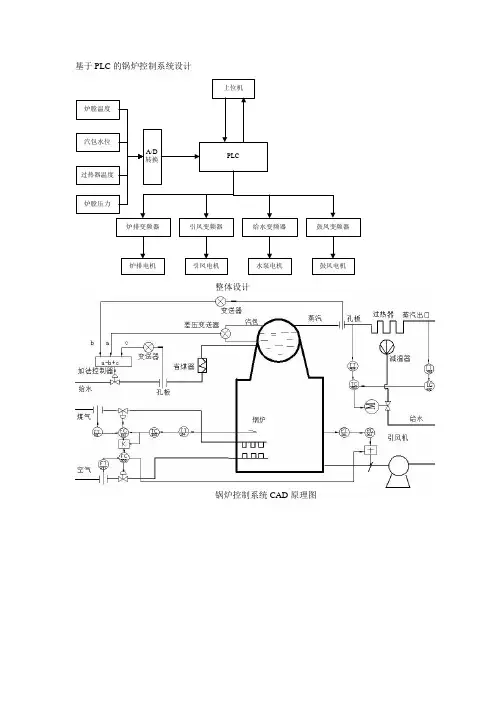
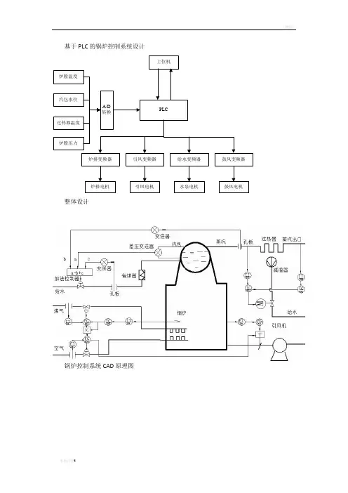
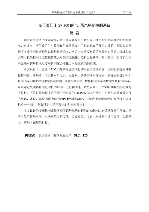
基于PLC 的锅炉控制系统设计
上位机
PLC
炉排变频器引风变频器给水变频器鼓风变频器
炉排电机鼓风电机
水泵电机引凤电机A/D 转换
炉膛压力
过热器温度
汽包水位
炉膛温度
整体设计
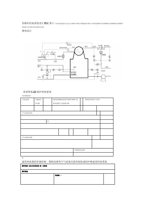
锅炉控制系统CAD 原理图
实际
测量
温度和流量的串级控制,煤粉流量和空气流量比值控制组成的炉膛温度控制系统
汽包水位的三冲量控制系统
炉膛负压前馈-反馈控制系统
过热器出口蒸汽温度串级控制系统
锅炉系统流程图设计
炉膛温度控制PLC程序流程图
汽包三冲量PLC程序流程图设计
炉膛负压PLC编程流程图设计
上下位机通信PLC编程流程设计。
锅炉控制系统原理图框
图和流程图
Coca-cola standardization office【ZZ5AB-ZZSYT-ZZ2C-ZZ682T-ZZT18】
基于PLC 的锅炉控制系统设计
上位机
PLC
炉排变频器引风变频器给水变频器鼓风变频器
炉排电机鼓风电机
水泵电机引凤电机A/D 转换
炉膛压力
过热器温度
汽包水位
炉膛温度
整体设计
锅炉控制系统CAD 原理图
实际
测量
温度和流量的串级控制,煤粉流量和空气流量比值控制组成的炉膛温度控制系统
汽包水位的三冲量控制系统
炉膛负压前馈-反馈控制系统
过热器出口蒸汽温度串级控制系统
锅炉系统流程图设计
炉膛温度控制PLC程序流程图
汽包三冲量PLC程序流程图设计
炉膛负压PLC编程流程图设计
上下位机通信PLC编程流程设计。
基于PLC 的锅炉控制系统设计
上位机
PLC
炉排变频器引风变频器给水变频器鼓风变频器
炉排电机鼓风电机
水泵电机引凤电机A/D 转换
炉膛压力
过热器温度
汽包水位
炉膛温度
整体设计
锅炉控制系统CAD 原理图
实际
测量
温度和流量的串级控制,煤粉流量和空气流量比值控制组成的炉膛温度控制系统
汽包水位的三冲量控制系统
炉膛负压前馈-反馈控制系统
过热器出口蒸汽温度串级控制系统
锅炉系统流程图设计
炉膛温度控制PLC程序流程图
汽包三冲量PLC程序流程图设计
炉膛负压PLC编程流程图设计
上下位机通信PLC编程流程设计。
基于西门子S7-300的40t蒸汽锅炉控制系统摘要随着社会经济的飞速发展,城市建设规模的不断扩大,以及人们生活水平的不断提高,对城市生活供暖的用户数量和供暖质量提出了越来越高的要求。
目前,我国大部分地区冬季生活供暖仍然以锅炉供暖为主,锅炉房自动控制系统配置相对落后,风机和水泵等电机的控制主要依赖值班人员的手工操作,控制过程繁琐,耗电耗煤,而且手动控制无法对锅炉供水温度和管网压力变化及时做出适当的反应。
本文设计了一套基于PLC和变频调速技术的供暖锅炉控制系统。
该控制系统由可编程控制器、变频器、风机和水泵电机、传感器、以及控制柜等构成。
系统主要包括四个控制回路:锅炉汽包水位控制回路、水温控制回路、炉排控制回路和炉膛负压控制回路。
系统通过变频器控制电动机的启动、运行和调速。
系统以西门子S7-300可编程控制器为下位机。
下位机控制程序采用西门子公司的STEP7编程软件设计,主要完成模拟量信号的处理,水位、温度和压力信号的PID控制等功能,并接收上位机的控制指令以完成风机启/停控制、参数设定、循环泵控制和补水泵控制。
本文设计的变频控制系统实现了锅炉燃烧过程的自动控制,有效地降低了能耗,提高了生产管理水平。
系统安装维护方便,运行稳定、可靠。
系统整体设计合理,功能齐全,实现了预期的目标。
关键词:锅炉控制,变频调速技术,PLC,PIDFor Siemens S7-300 40 Tons Steam Boiler Control SystemAbstractWith the rapid development of social economy and the increasingly improved living standard of people, the scale of city construction is unprecedentedly expanded, arousing urgent requirement for high-quality living heating system to meet the sustainingly increased need. In the majority of our country, however, most current living heating systems for winter use are relatively still out-of-date boiler heating system, in which, the core part, namely, the control of operating fans in stokehold and water pumps is still manual and therefore hard to realize real-time adjustment according to changing pressure in the pipes and temperature of water supplied. Consequently, this fussy manual control inevitably leads to unnecessary huge waste of coal and electrical power.In this paper, a heating boiler control system based on PLC and variable frequency speed-regulating technology is designed. The control system is made up of PLC, transducers, electromotor units of pumps and fans, sensors and control tanks, etc. In the program control system is consisted by four loops that is the water level control loop, the water temperature control loop, the boilers belt control loop and the hearth pressure control loop. It can control electromotor starting, running and timing by means of transducers. The hardware system adopts a Siemens S7-300 PLC as the lower control system (LCS). The control software of LCS designed with STEP7(Siemens PLC software toolbox) is mainly used to deal with functions such as processing analog signals , PID control of water level、temperature and pressure, and accepting control instructions from the upper supervisory system(USS) to realize starting/stopping of electromotors, setting of analog parameters and control of water pumps.The frequency control system proposed not only can realize automatic control of boiler burning process efficiently, having greatly reduced energy consumption, and in the meantime effectively improved the level of boiler control management, but also has many advantages such as stable and reliable running, flexible operation, etc. The whole design is feasible and reliable and reach the expected objective..Key words:boiler control, variable frequency speed-regulating technology, PLC,PID目录摘要........................................................................................................................................... I ABSTRACT .............................................................................................................................. II 1绪论. (1)1.1引言 (1)1.2蒸汽锅炉设备的基本结构 (1)1.2.1蒸汽锅炉本体 (1)1.2.2辅助设备 (2)1.3蒸汽锅炉的工作过程 (3)1.3.1燃料燃烧与通风系统 (3)1.3.2汽-水系统 (3)1.4控制要求 (3)1.4.1控制汽包水位 (4)1.4.2控制蒸汽温度 (4)1.4.3控制炉膛压力 (4)1.4.4控制燃烧系统 (5)1.4.5控制鼓风引风量 (5)2 PLC硬件设计 (6)2.1PLC的发展历程 (6)2.2PLC特点 (6)2.3S7-300简介 (8)2.4系统组成 (8)3软件设计 (10)3.1S7-300编程软件简介 (10)3.2控制系统软件设计 (11)3.2.1控制算法的选择 (11)3.2.2 STEP7中的PID功能块 (12)3.2.3主程序设计 (12)3.2.4子程序设计 (13)结论 (19)致谢 (20)参考文献 (21)附录A (S7-300-PLC MODULE SPECIFICATION) (22)附录B(S7-300模板规范手册) (30)附录C (蒸汽锅炉控制系统原程序) (36)1 绪论1.1 引言供暖锅炉控制系统属于过程控制系统,其控制的目标是控制锅炉燃烧过程中的水位、炉膛负压等参数,使锅炉燃烧工况良好,保证设备运行安全,满足用户的供热要求。