麦氏真空规通用技术规范
- 格式:doc
- 大小:61.50 KB
- 文档页数:7

畜禽屠宰加工设备通用要求1范围本文件规定了畜禽屠宰加工设备的基本要求、加工要求、装配要求、安装要求、安全要求、检查与试验要求、检验规则及标志、包装、运输和贮存要求。
本文件适用于畜禽屠宰加工设备的设计、制造、安装、检验和使用管理。
2规范性引用文件下列文件中的内容通过文中的规范性引用而构成本文件必不可少的条款。
其中,注日期的引用文件,仅该日期对应的版本适用于本文件;不注日期的引用文件,其最新版本(包括所有的修改单)适用于本文件。
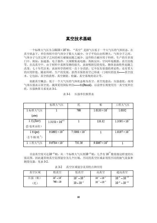
GB/T116铆钉技术条件GB/T150.1压力容器第1部分:通用要求GB/T150.4压力容器第4部分:制造、检验和验收GB/T191包装储运图示标志GB/T491钙基润滑脂GB/T492钠基润滑脂GB/T1031产品几何技术规范(GPS)表面结构轮廓法表面粗糙度参数及其数值GB/T1348球墨铸铁件GB/T1731漆膜、腻子膜柔韧性测定法GB/T1732漆膜耐冲击测定法GB/T1740—2007漆膜耐湿热测定法GB/T2100一般用途耐蚀钢铸件GB2894安全标志及其使用导则GB/T3323.1焊缝无损检测射线检测第1部分:X和伽马射线的胶片技术GB/T3766液压系统通用技术条件GB/T3767声学声压法测定噪声源声功率级反射面上方近似自由场的工程法GB/T3768声学声压法测定噪声源声功率级反射面上方采用包络测量表面的简易法GB/T4208外壳防护等级(IP代码)GB4853食品级白油GB/T5210色漆和清漆拉开法附着力试验GB/T5226.1机械电气安全机械电气设备第1部分:通用技术条件GB5749生活饮用水卫生标准GB/T6400金属材料线材和铆钉剪切试验方法GB/T6414铸件尺寸公差与机械加工余量GB/T6576机床润滑系统GB/T6739色漆和清漆铅笔法测定涂膜硬度GB/T7932气动系统通用技术条件GB/T7935液压元件通用技术条件GB/T8196机械安全防护装置固定式和活动式防护装置设计与制造一般要求GB/T9438铝合金铸件GB/T9439灰铁铸件GB/T9440可锻铸铁件GB/T10089圆柱蜗杆、蜗轮精度GB/T10095.1圆柱齿轮ISO齿面公差分级制第1部分:齿面偏差的定义和允许值GB/T10095.2圆柱齿轮ISO齿面公差分级制第2部分:径向综合偏差的定义和允许值GB/T10595带式输送机GB11341悬挂输送机安全规程GB/T11351铸件重量公差GB/T11365锥齿轮精度制GB/T12265机械安全防止人体部位挤压的最小间距GB/T13306标牌GB/T13384机电产品包装通用技术条件GB/T13452.2色漆和清漆漆膜厚度的测定GB/T13819铜及铜合金铸件GB15179食品机械润滑脂GB16798食品机械安全要求GB17888.2机械安全进入机械的固定设施第2部分:工作平台和通道GB17888.3机械安全进入机械的固定设施第3部分:楼梯、阶梯和护栏GB/T18194铆钉杆径GB50168电气装置安装工程电缆线路施工及验收标准GB50270输送设备安装工程施工及验收规范GB50317猪屠宰与分割车间设计规范GB51219禽类屠宰与分割车间设计规范GB51225牛羊屠宰与分割车间设计规范JB/T7277操作件技术条件JB/T9168切削加工通用工艺守则3术语和定义下列术语和定义适用于本文件。

AMS 2750E高温测定法5 年一次的更新,复查并重审了该规范以提高其使用量,技术革新导致了使用的变化。
变化范围较大并且没有做标记。
目录1.范围 (3)2.引用文件 (3)2.1 ASTM 出版物 (3)2.2 定义 (3)3.技术要求 (8)3.1温度传感器 (8)3.2 仪表(见表3, 4, 和表5) (12)3.3 热处理设备: (16)3.4 系统精度测试(SA Ts) (18)3.5 炉温均匀性测试(TUS) (23)3.6 实验室炉子 (33)3.7 记录 (33)3.8 取舍 (33)4. 质量保证条款 (33)4.1 检验职责 (33)5. 交货准备 (42)6. 接收 (42)7. 拒收 (42)8. 注释 (43)图1 负载传感器的使用和重新校检 (13)图2 不同类型炉子的炉温均匀性范围 (16)图3 仪表类型要求 (17)图4 每个区域最少传感器支数 (18)图5固定的SAT传感器与在500℉ (260℃)以上温度测试的传感器的允许组合 (19)图6 系统精度测试(SA T)计算的实例 (21)表1 传感器和传感器校检 (34)表2 热电偶和补偿导线 (35)表3 使用仪器及校准 (36)表4 炉子记录图表的确定要求 (38)表5 记录器打印图表及速度 (38)表6 零件所用炉子分类、仪表类型以及SA T校验周期 (39)表7 原材料炉所用炉子分类、仪表类型以及SA T校验周期 (40)表8 零件所用炉子分类、仪表类型以及和TUS校验周期 (41)表9 原材料炉所用炉子分类、仪表类型和TUS校验周期 (41)表10 校验或试验间隔延长的容许值 (42)表11 TUS传感器数量要求 (42)附录A:E版与D版变更内容说明 (42)1.范围1.1 本规范涵盖了热处理过程中用到的热处理设备的高温测量要求,包括温度传感器,仪器仪表,热处理设备,系统精度测试和温度均匀性测量。
这些对于确保零部件或原材料的热处理符合适用规范要求是很有必要的。
使用说明书VGC402双通道测量与控制仪器VGC403三通道测量与控制仪器目录1 前言1.1 有效性1.1.1 件号1.1.2 固件版号1.1.3 型号标签1.2 用途1.2.1 责任与保修1.3 产品型号1.4 安全1.4.1 人员要求1.4.2 使用符号1.4.3 一般安全规则2 技术参数2.1 一般参数2.1.1 机械参数2.1.2 环境条件2.1.3 操作2.1.4 标准2.2 电源连接2.3 通道2.3.1 规管连接件2.3.2 规管电源2.3.3 测量技术2.4 开关功能2.4.1 开关功能继电器2.4.2 误差讯号继电器2.5 输出2.5.1 模拟输出2.5.2 记录仪输出2.5.3 计算机接口2.6 供货范围3 安装3.1 开箱3.2 机械安装3.2.1 桌上式仪器3.2.2 安装在控制屏上3.2.3 机架安装3.3 连接3.3.1 设备后板3.3.2 电源连接3.3.3 接地3.3.4 SENSOR3.3.5 RELAY3.3.6 CONTROL 3.3.7 RS232C 4 运行4.1 面板4.1.1 显示器4.1.2 控制按钮4.2 电源on和iff4.2.1 电源on4.2.2 电源off4.2.3 延迟时间4.3 工作模式4.4 测量模式4.4.1 选择4.4.2 说明4.4.3 控制按钮功能4.5 参数模式4.5.1 选择4.5.2 参数组4.5.3 基本操作5 参数5.1 转换功能参数(PArA SP) 5.1.1 基本术语5.1.2 配置转换功能5.1.3 设定值范围5.2 规管参数(PArA SEn) 5.2.1 测量筛选器(FILt)5.2.2 气体类型(GAS)5.2.3 测量范围(FS)5.2.4 偏离(oFS)5.2.5 除气功能(dEGAS)5.2.6 规管启用(S-on)5.2.7 开关on阈值(t-on)5.2.8 规管停用(S-oFF)5.2.9 开关off阈值(t-off)5.3 一般参数(PArA GEn) 5.3.1 测量单位(unit)5.3.2 波特率(bAud)5.3.3 显示方式(diGIt)5.3.4 缺省参数(dEF)5.3.5 记录仪输出(Ao)5.3.6 误差讯号继电器(Err-r) 5.4 测试参数(PArA tESt) 5.4.1 选择5.4.2 固件版号(Pnr)5.4.3 监测器控制(dt-C)5.4.4 乇锁(tr-L)5.4.5 参数设置(LoC)5.4.6 RAM测试(rA-t)5.4.7 EPROM测试(EP-t) 5.4.8 EEPROM测试(EE-t) 5.4.9 显示器测试(dI-t)5.4.10 A/D变换器讯号(Ad-S) 5.4.11 A/D变换器ID(Ad-I) 5.4.12 I/O测试(Io-t)5.4.13 RS232C测试(rS-t)6 计算机接口6.1 基础6.1.1 连接件6.1.2 术语6.2 通讯6.2.1 协议6.2.2 发送(Host♑Unit)6.2.3 接收(Unit ♑Host)6.2.4 例6.2.5 数格式6.2.6 连续测量传送6.3 助记符6.3.1 一览表6.3.2 AOM6.3.3 BAU6.3.4 COM6.3.5 COR6.3.6 DCD6.3.7 DGS6.3.8 ERA6.3.9 ERR6.3.10 FIL6.3.11 FER6.3.12 GAS6.3.13 HVC6.3.14 ITR6.3.15 LOC6.3.16 OFC6.3.17 OFD6.3.18 PNR6.3.19 PRI6.3.20 PRX6.3.21 RES6.3.22 SAV6.3.23 SC16.3.24 SP16.3.25 SPS6.3.26 TAD6.3.27 TDI6.3.28 TEE6.3.29 TEP6.3.30 TID 6.3.31 TIO6.3.32 TKB6.3.33 TLC6.3.34 TRA6.3.35 TRS6.3.36 UNI6.3.37 WDT7 维护和服务7.1 维护7.1.1 清洗7.2 程序传送模式7.2.1 准备和选择7.2.2 程序传送7.2.3 重新启动7.3 故障查找7.3.1 故障指示7.3.2 误差信息7.3.3 技术支持7.3.4 检修7.4 校准7.4.1 基础7.4.2 CAO7.4.3 CAF7.4.4 校准单位8 贮存和废物处理8.1 包装8.2 贮存8.3 废物处理附录转换表重量压强线性测量温度转换缺省参数文献资料索引质量保证书1 前言1.1 有效性1.1.1 件号本文件用于下列产品:件号产品398-020 398-021 VGC402 VGC403在仪器一侧的型号标签上标有件号。
IR 090热阴极电离复合真空计使用说明书BG 804 171 BE目录产品标识有效范围使用范围工作原理注册商标1 安全1.1 使用符号1.2 人员素质1.3 一般安全规则1.4 赔偿责任与保修2 技术参数3 安装3.1 真空连接3.1.1 拆卸和安装电子学单元3.1.2 安装延伸件3.2 电源连接3.2.1 与COMBIV AC IT23一起使用3.2.2 与其它测量仪器一起使用4 运行4.1 测量原理,测量特性4.2 真空计工作原理4.3 除气4.4 显示器4.5 RS232C接口4.5.1 功能说明4.5.1.1 IR090输出4.5.1.2 IR090输入5 维护5.1 维护5.2 真空计调整5.3 真空计清洗5.4 安装障板5.5 更换障板5.6 更换规管5.7 故障查找6 拆卸7 产品返修8 附件9 备件10 废物处理附录A. 测量讯号与压强的关系B. 气体种类与压强的关系污染申报表参阅本说明书中的章节,采用符号(→XY)。
参阅其它文献,采用符号(→[Z])。
产品标识与Leybold Inficon联系时,请标明产品标牌上给出的信息。
将信息复制在标牌的复印件上。
有效范围本说明书适用于下列件号的产品不带显示器120 90 (法兰DN 25 ISO-KF)120 92 (法兰DN 40 CF-R)带显示器120 91 (法兰DN 25 ISO-KF)120 94 (法兰DN 40 CF-R)产品的件号在标牌上标明。
本公司保留对说明书不预先通知的技术更改权。
使用范围I R090用于在压强5×10⁻¹⁰…1000毫巴范围内非易燃性气体和气体混合物的真空测量。
真空计规管是SKY Smart真空计规管系列的一个组成部分。
可与COMBIV AC IT23或其它测量仪器一起工作。
工作原理在整个测量范围内,热阴极电离复合真空计有连续的测量特性。
它的测量讯号是对数压强输出。
真空计的功能包括BA规热阴极电离测量系统(用于p<2.0×10⁻²毫巴)和皮拉尼测量系统(用于p>5.5×10⁻³毫巴)。

真空感应熔炼炉技术要求1.技术要求1.1 主要技术参数 规格、尺寸、基本安装条件 立式炉体 一次出钢量 达到500Kg 额定功率 400kw 额定电压(感应端电压) 500V 最高温度 1700℃ 额定频率 700Hz ,1000Hz 。
极限真空度 6.7×10⁻²Pa 压升率 ≤1Pa/h 耗水量 40m 3/h 成套设备总重量约 40t ZL-800油增压泵功率 30kw ZJP-1200DV 罗茨泵功率 2×11Kw (真空感应熔炼炉配置两台罗茨泵) 2H-150DV 滑阀泵电机功率 2×11Kw (真空感应熔炼炉配置两台滑阀泵) 成套设备总功率 约500 Kw 电源 IGBT 双频电源1.2设备关键部件规格要求序号 名称 型号、材质要求 制造厂要求 1 炉体内壁304不锈钢,外壁碳钢 2 滑阀泵 型号2H-150DV 三门拓展真空设备有限公司生产或同级别产品3罗茨泵 型号Z J P-1200DV 三门拓展真空设备有限公司或同级别产品 4油增压喷射泵 型号Z-800 甘肃腾飞有限公司或同级别产品 5旋片泵 型号2X-70、2X-8 三门拓展真空设备有限公司或同级别产品 6真空气动蝶阀 型号GIQ-80 上海阀门二厂或 宁波仪表阀门厂 7隔膜阀 型号GM-10F 、GM-40F 上海阀门二厂或 宁波仪表阀门厂 8真空计 型号ZDF-Ⅲ复合真空计 成都睿宝或成都成华 9300气动插板阀 不锈钢产品 上海阀门二厂或同级别产品 10 电源400KW,IGBT 电源, 双频电源,700Hz 和1000Hz 。
配有漏钢自动保护和自动报警功能 张家港四通或同级别产品 11各电机 节能电机,达到标准IE2以上 12 钢锭摆放量最多可摆放6个钢锭模,步进式,浇注高度1.25米,浇注平台宽度1.5米 13密封胶圈 密封胶圈的设计要避免高温高辐射,接触高温高辐射部分健全要求使用硅橡胶或其它耐高温橡胶 14红外测温 700℃-1800℃,MR 系列 美国雷泰或同级别产品 15PLC 德国西门子或同级别产品1.3、设备结构说明成套设备由真空熔炼室(包括炉体、炉盖)、真空系统、液压系统、水冷系统、气动系统、主加料装置、合金加料箱及料斗翻转机构、观察窗、进电装置、测温装置、捣料装置、工作台、锭模车、IGBT中频电源柜及电气控制系统等部分组成,实现在真空状态下作业的工艺要求。

Issue GInstruction ManualWide Range GaugeDescription Item NumberWRG-S-NW25D147-01-000WRG-SL-NW25D147-11-000WRG-D-NW25D147-02-000WRG-S-DN40CF D147-03-000This product has been manufactured under a quality system registered to ISO9001Declaration of ConformityMr L. Marini, Technical ManagerDate and PlaceP 200-02-460 I s s u e D9 December 2009© Edwards Limited 2010. All rights reserved.Page iEdwards and the Edwards logo are trademarks of Edwards Limited.ContentsD147-01-880 Issue GContentsSectionPage1Introduction (1)1.1Scope and definitions ...................................................................................................11.2Description ................................................................................................................11.3Gas dependency (2)2Technical data (5)2.1Mechanical data ..........................................................................................................52.2Performance, operating and storage conditions ....................................................................52.3Electrical data ............................................................................................................52.4Materials exposed to vacuum (6)3Installation (11)3.1Unpack and inspect .....................................................................................................113.2Fit the WRG to the vacuum system ..................................................................................113.3Electrical connections ..................................................................................................113.3.1Connect to Edwards controllers or AGD display ....................................................................113.3.2Connect to your own supply and control equipment (11)4Operation (13)4.1Safety .....................................................................................................................134.2Pressure measurement .................................................................................................144.3Atmosphere adjustment ...............................................................................................144.4Vacuum adjustment ....................................................................................................154.5Set-point .................................................................................................................154.6Error monitoring (16)5Maintenance (17)5.1Introduction .............................................................................................................175.2Replace the body tube .................................................................................................175.3Replace the electrode and pirani assemblies ......................................................................185.4Replace the electronics and magnet housing ......................................................................195.5Clean the internal components (19)6Storage and disposal (21)6.1Storage ...................................................................................................................216.2Disposal (21)7Service, spares and accessories (23)7.1Introduction .............................................................................................................237.2Service ....................................................................................................................237.3Spares .....................................................................................................................237.4Accessories ...............................................................................................................24For return of equipment, complete the HS Forms at the end of this manual.g e a /0084/05/10D147-01-880 Issue GPage ii© Edwards Limited 2010. All rights reserved.Edwards and the Edwards logo are trademarks of Edwards Limited.ContentsIllustrationsFigurePage1General view of the WRG-S and -SL ...................................................................................22General view of the WRG-D ............................................................................................33Dimensions (mm) of the WRG-S-NW25 and WRG-SL-NW25 ........................................................74Dimensions (mm) of the WRG-D-NW25 ...............................................................................85Dimensions (mm) of the WRG-S-DN40CF .............................................................................96Schematic diagram of typical electrical connections for the WRG .............................................127Pressure-voltage characteristic of the WRG ........................................................................148Refitting the body tube assembly (189)Exploded view of the body tube assembly (20)TablesTablePage1Pin identification (12)Trademark creditsScotchbrite™ is a trademark of 3M Global Trading, Inc.© Edwards Limited 2010. All rights reserved.Page 1Edwards and the Edwards logo are trademarks of Edwards Limited.IntroductionD147-01-880 Issue G1Introduction1.1Scope and definitionsThis manual provides installation, operation and maintenance instructions for the Edwards WRG (Wide Range Gauge). You must use the WRG as specified in this manual.Read this manual before you install and operate the WRG. Important safety information is highlighted as WARNING and CAUTION instructions; you must obey these instructions. The use of WARNINGS and CAUTIONS is defined below.CAUTIONCautions are given where failure to observe the instruction could result in damage to the equipment, associated equipment or process.The units used throughout the manual conform to the SI international system of units of measurement.The following symbol is on the Wide Range Gauge:1.2DescriptionThe Wide Range Gauge, shown in Figure 1, is a combined inverted magnetron and pirani gauge in a single compact unit.The WRG incorporates a unique striking mechanism consisting of a small incandescent filament mounted inside the magnetron tube. This filament is automatically ignited providing enough emission electrons to initiate the discharge.The WRG incorporates an intelligent microprocessor based control system which is used to control the various features such as:●Automatic control of the magnetron HT voltage during the ignition of the gauge.●Reduction of the HT voltage after ignition to enhance the life time of the gauge.●Automatic adjustment of the pirani vacuum reading.●Provision of an error monitoring feature which will help identify the exact cause of failure.●Simple adjustment of the set-point trip level.Three versions of the Wide Range Gauge are available: the ‘S’, ‘SL’ and the ‘D’ gauges. The ‘S’ and ‘SL’ versions have an FCC68 connector socket while the ‘D’ version has a 9 way D-type socket. The ‘SL’ gauges have a very low external magnetic field and are suitable for use with sensitive analytical instruments. The ‘S’ version is available with either a NW25 or DN40CF flange.The WRG is compatible with the AGC range (Active Gauge Controllers) and with the appropriate versions of the AGD (Active Gauge Display). Alternatively, an independent power supply can be used for the WRG and the output signal can be read with a voltmeter or an analogue-to-digital converter.WARNINGWarnings are given where failure to observe the instruction could result in injury or death to people.From August 2005, Edwards will offer European customers a recycling service.D147-01-880 Issue GPage 2© Edwards Limited 2010. All rights reserved.Edwards and the Edwards logo are trademarks of Edwards Limited.IntroductionThe WRG has a set-point facility. The set-point signal is an open collector transistor output, which is on when the pressure measured by the gauge is below a preset pressure. You can adjust the pressure at which the set-point output is activated, refer to Section 4.5.Note:If you use an Active Gauge Controller or Active Gauge Display, the WRG set-point output signal is not used.1.3Gas dependencyIn the pirani measurement range the rate of heat transfer through a gas is dependent upon both the pressure and the RMM (Relative Molecular Mass) of the gas. Similarly, in the inverted magnetron measurement range the ionisation of the gas in the vacuum system is dependent on both the pressure and the physical properties of the gas. Therefore, the output signal of the WRG is gas dependent.The output signal voltage to pressure conversion in Section 4.2 applies for nitrogen and dry air. Calibration graphs for use with other commonly used gases are available on request.Figure 1 - General view of the WRG-S and -SL1.Set atmosphere2.Set trip3.Electronics housing4.Vacuum flange5.Magnet housing6.Cable strain relief7.Cable connector plug8.Connector socket© Edwards Limited 2010. All rights reserved.Page 3Edwards and the Edwards logo are trademarks of Edwards Limited.IntroductionD147-01-880 Issue GFigure 2 - General view of the WRG-D1.Set atmosphere2.Set trip3.Electronics housing4.Vacuum flange5.Magnet housing6.Cable strain relief7.Cable connector plug8.Connector socketD147-01-880 Issue GThis page has been intentionally left blank.Page 4© Edwards Limited 2010. All rights reserved.Edwards and the Edwards logo are trademarks of Edwards Limited.© Edwards Limited 2010. All rights reserved.Page 5Edwards and the Edwards logo are trademarks of Edwards Limited.Technical dataD147-01-880 Issue G2Technical data2.1Mechanical data2.2Performance, operating and storage conditions2.3Electrical dataDimensions See Figure 3, 4 and 5MassWRG-S-NW25750 g WRG-D-NW25750 g WRG-SL-NW25800 g WRG-S-DN40CF 1000 g Volume of gauge tube 26 cm 3Enclosure ratingWRG-S-NW25IP40WRG-SL-NW25IP40WRG-S-DN40CF IP40WRG-D-NW25IP44 (provided that the gauge is mounted vertically withthe vacuum flange at the bottom)Ambient temperatureOperation 5 to 60 °C Storage0 to 70 °CAmbient humidity (operation)max 90% RH (non-condensing) up to 31 °C max 70% RH (non-condensing) above 31 °C Maximum internal pressure 6 bar absolute (5 bar gauge)Maximum operating altitude 2000 m (indoor use only)Pressure measurement range 100 to 10-9 mbar (indicates pressures up to 1000 mbar at reduced accuracy)Pollution degree2Electrical supplyVoltage+14.5 to +36 V d.c.Max voltage ripple 1 V peak to peak Max source resistance 50 ΩMaximum power consumption 2 WElectrical connectorWRG-S-NW25FCC68/RJ45 type, 8-way WRG-SL-NW25FCC68/RJ45 type, 8-way WRG-S-DN40CF FCC68/RJ45 type, 8-way WRG-D-NW259 way D-type maleD147-01-880 Issue GPage 6© Edwards Limited 2010. All rights reserved.Edwards and the Edwards logo are trademarks of Edwards Limited.Technical data2.4Materials exposed to vacuum●Stainless steel (AISI 304, 316, 321, 347)●Fluoroelastomer ●Soda lime glass ●T ungsten●Trace of Nickel and Nickel ironPressure output signalRange 2 - 10 V d.c.Error range < 1.5 V d.c. or > 10.15 V d.c.Impedance0.1 ΩMin load impedance 10 k ΩMax current source1 mASet-point output external load rating 40 V d.c., 100 mA max Set-point trip levelRange 1.8 to 10.2 V Hysteresis330 mV Back EMF suppression diode *Min. surge rating1 A Min. reverse voltage rating 100 V Atmosphere calibration inputControl sense Active low Active level < 1.5 VControl impedance 100 k Ω pull-up to positive supply Gauge identification resistance75 k Ω ± 2%*Required when you use an external d.c. relay connected to the set-point output.© Edwards Limited 2010. All rights reserved. Page 7 Edwards and the Edwards logo are trademarks of Edwards Limited.Technical dataFigure 3 - Dimensions (mm) of the WRG-S-NW25 and WRG-SL-NW25Page 8© Edwards Limited 2010. All rights reserved.Edwards and the Edwards logo are trademarks of Edwards Limited.Technical dataFigure 4 - Dimensions (mm) of the WRG-D-NW25© Edwards Limited 2010. All rights reserved. Page 9 Edwards and the Edwards logo are trademarks of Edwards Limited.Technical dataFigure 5 - Dimensions (mm) of the WRG-S-DN40CFThis page has been intentionally left blank.Page 10© Edwards Limited 2010. All rights reserved.Edwards and the Edwards logo are trademarks of Edwards Limited.© Edwards Limited 2010. All rights reserved.Page 11Edwards and the Edwards logo are trademarks of Edwards Limited.Installation 3Installation 3.1Unpack and inspectRemove all packing materials and protective covers and check the WRG.If the WRG is damaged, notify your supplier and the carrier in writing within three days; state the Item Number of the WRG together with your order number and your supplier’s invoice number. Retain all packing materials for inspection. Do not use the WRG if it is damaged.If the WRG is not to be used immediately, replace the protective covers. Store the WRG in suitable conditions as described in Section 6.3.2Fit the WRG to the vacuum systemThe WRG can be mounted in any orientation. To avoid the build-up of debris or condensable material in the body tube of the WRG (which might cause pressure measurement errors), we recommend that you install the WRG vertically as shown in Figure 3, 4 and 5.Use an O-ring / centring ring or Co-Seal and clamp to connect the NW25 flange of the WRG to a similar flange on your vacuum system.Use a copper gasket and screws to connect the DN40CF flange of the WRG-S-DN40CF to a similar flange on your vacuum system.3.3Electrical connectionsWhen using a cable longer than 30 m, full compliance with the EN61326 requires an in-line surge suppressor (please refer to Section 7.4).3.3.1Connect to Edwards controllers or AGD displayConnect the WRG to the controller or display with a cable which is terminated in suitable connectors. Suitable cables are available upon request. (See Section 7.4).3.3.2Connect to your own supply and control equipment Note:You should not connect the electrical supply common (pin 2) to the signal common (pin 5). If you do, theWRG pressure output signal may be inaccurate.A schematic diagram of the recommended electrical connections to the WRG is shown in Figure 6.The pins of the FCC68 and D-type sockets on the WRG electrical connection are used as shown in Table 1.WARNINGThe WRG incorporates magnets. Keep away from heart pacemakers, computers, credit cards andany other magnetically sensitive devices.WARNINGIf the WRG malfunctions, the WRG pressure output may be incorrect. If such a failure could causeinjury to people or damage equipment, you must install a suitable control system to indicate thefailure and, if necessary, to close down your process system.Page 12© Edwards Limited 2010. All rights reserved.Edwards and the Edwards logo are trademarks of Edwards Limited.InstallationConnections to pins 4, 6 and 7 are optional. Make the connection to pin 6 if you want to connect the set-point output signal to a d.c. relay. You must connect a suppression diode between pin 1 and 6 to protect the WRG from transient voltage generated when the d.c. relay is switched off.Measure between pins 4 and 5 to determine the value of the ID resistor.Connect a switch between pins 2 and 7 to enable calibration of the gauge at atmosphere and vacuum. (Refer to Section 4.3 and 4.4).Figure 6 - Schematic diagram of typical electrical connections for the WRG Table 1 - Pin identification Pin Number Connection 1Supply positive 2Supply common 3Signal output 4ID resistor 5Signal common 6Set-point output 7Atmosphere calibration 8Not connected 9Not connected (D-type connector only)A.Electrical supply B.Voltmeter (pressure signal)C.Back EMF suppression diode (optional) D. D.C. relay (optional)E.Atmosphere calibration switch F .Pin 9 of D-type connector (optional) (not in use)© Edwards Limited 2010. All rights reserved.Page 13Edwards and the Edwards logo are trademarks of Edwards Limited.Operation 4Operation 4.1SafetyCAUTION The WRG has a magnet which may affect sensitive devices such as floppy disks. The effect is reduced on the -SL version.WARNINGDo not use the WRG to measure the pressure of explosive or flammable gases or mixtures.WARNINGNever operate the WRG when it is disconnected from the vacuum system or when there areexplosive or flammable gases in the surrounding atmosphere or the vacuum system. High voltages(up to 3 kV) are generated inside the body tube of the WRG; these could cause injury to people orcould be a source of ignition.WARNINGDo not disconnect the electronics and magnet housing from the body tube when the body tube isconnected to the vacuum system. If there is a plasma discharge in the vacuum system near thebody tube, the body tube can become electrically charged.WARNINGWhen the pressure of gases of high molecular weight are measured, the pressure indicated can bebelow the true pressure. Ensure that the WRG is not over-pressurised when you use heavy gases.WARNINGUse the gauge only for its intended purpose as described in this instruction manual.WARNINGThe WRG incorporates magnets. Keep away from heart pacemakers, computers, credit cards andany other magnetically sensitive devices.Page 14© Edwards Limited 2010. All rights reserved.Edwards and the Edwards logo are trademarks of Edwards Limited.Operation 4.2Pressure measurementIf you connect the WRG to an Edwards AGC controller or AGD display, the pressure measured by the WRG is shown on the display.If you connect the signal output of the WRG to a voltmeter, convert the measured voltage to the corresponding pressure value using the following equation:where V is the measured voltage. For example, if the measured voltage V = 4, then pressure P = 10-6 mbar. Refer also to Figure 7.4.3Atmosphere adjustmentUse the “ATM” switch (see Figure 1 and 2, item 3) or pin 7 and 2 to set the reading at atmosphere.Switch on the power supply to the WRG and allow it to operate at atmospheric pressure for at least 10 minutes.With the vacuum system at atmospheric pressure, press the “ATM” switch with an appropriate tool. The output of the gauge will be automatically adjusted to read atmosphere.Figure 7 - Pressure-voltage characteristic of the WRGP =10(1.5 V-12) mbar= 10(1.5 V-10) Pascal= 10(1.5 V-12.125)torr© Edwards Limited 2010. All rights reserved. Page 15 Edwards and the Edwards logo are trademarks of Edwards Limited.Operation4.4Vacuum adjustmentThe WRG will perform the pirani sensor vacuum setting automatically every time the WRG is pumped down to a pressure lower than 10-4 mbar. Therefore a manual setting of vacuum is not required unless the pirani tube is replaced.If the gauge fails to indicate pressure of < 10-3 mbar, then a manual vacuum setting is required. To perform this operation, follow the procedure below.Reduce the system pressure to 10-5 mbar or below and wait for 1 minute. Press and release the “ATM” switch and wait for approximately 30 seconds until the adjustment is completed. Manual adjustment of the vacuum reading is recommended when replacing the pirani tube or after a long period of storage.If an operator has tried to set the atmosphere or vacuum reading while the actual pressure is between10-2 and 102 mbar, an error voltage of 1 V will be displayed indicating a pirani failure. See Section4.6.4.5Set-pointNote:The set-point is not used if you connect the WRG to an Edwards Active Gauge Controller or Active Gauge Display.To read the voltage at which the set-point output signal is activated, press the set trip switch (see Figure1 and 2) with an appropriate tool. The output of the gauge will indicate the set trip level for 3 seconds after which the output will read the normal voltage output.To adjust the voltage at which the set-point output signal is activated, press the set trip switch and hold it down for more than 3 seconds. The set-point voltage will start scrolling upwards. Remove pressure from the switch as soon as you reach the required trip voltage. To make a finer adjustment, remove pressure from the set trip switch and immediately depress the switch as many times as required. Each depression will increase the set trip voltage by about 10 mV. Refer to Section4.2 to determine the operating voltage which corresponds to a given pressure.The WRG has an error monitoring facility, which ensures that the set-point output signal is off:●when the gauge is switched off●for 2 seconds immediately after the WRG is switched on●when the pressure output signal is out of range●when an error voltage is detected, see Section4.6If required, you can adjust the set-point operating voltage to < 1.9 V. This ensures that the set-point output is permanently off.If required, you can use the set-point output signal to indicate when the gauge is operating correctly. Adjust the set-point operating voltage to > 10.15 V. The set-point output will then be on if the gauge is operating normally, and off if an error condition is detected.Note:If you adjust the set-point operating voltage to > 9.7 V, the hysteresis voltage will be > 10 V and the set-point output signal may not switch off when the pressure rises. If so, the set-point output signal will switch off only when the gauge is switched off.Page 16© Edwards Limited 2010. All rights reserved.Edwards and the Edwards logo are trademarks of Edwards Limited.Operation 4.6Error monitoringThe gauge is able to perform some internal error monitoring functions, and respond in a defined manner, assummarised below. These operate in conjunction with the user controls to define the gauge operation. The responses are prioritised in the order shown.The error condition is reset (cleared) when the gauge is disabled or power is removed.The error condition ‘striker filament broken’ will occur only if the inverted magnetron fails to strike.The set-point will be disabled as soon as one of the above errors is detected.Error indications:Output Voltage Edwards Controllers Output Pirani failure 1 V ERR AInverted magnetron contaminated or short circuited 1.1 V ERR BStriker filament broken 1.2 V ERR CInverted magnetron not struck 1.3 VERR D© Edwards Limited 2010. All rights reserved.Page 17Edwards and the Edwards logo are trademarks of Edwards Limited.Maintenance5Maintenance5.1IntroductionThe internal components of the WRG are shown in Figure 8. The WRG is designed so that you can clean thesecomponents, or use the spares listed in Section 7.3 to replace these components. Refer to the following sections for details of maintenance procedures, which you should perform when necessary.5.2Replace the body tubeRefer to Figure 8 and use the following procedures to replace the body tube.To remove the body tube assembly:Switch off the WRG electrical supply and ensure that the vacuum system is at atmospheric pressure.Disconnect the cable connector plug (Figure 1 and 2, item 7) and remove the WRG from the vacuum system.Hold the magnet housing firmly and pull the body tube assembly to remove.To refit the body tube assembly:Insert the body tube assembly into the magnet housing and then rotate it while maintaining gentle pressure until the tube assembly locates. Push fully home until the locking spring snaps into position.Refit the gauge to the vacuum system as described in Section 3.2 and reconnect the electrical supply.WARNINGDo not disconnect the electronics and magnet housing from the body tube when the body tube is connected to the vacuum system. If there is a plasma discharge in the vacuum system near the body tube, the pins of the anode assembly can become electrically charged.WARNINGDisconnect the cable from the WRG before you remove the WRG from the vacuum system. Highvoltages are generated inside the WRG.Page 18© Edwards Limited 2010. All rights reserved.Edwards and the Edwards logo are trademarks of Edwards Limited.MaintenanceFigure 8 - Refitting the body tube assembly5.3Replace the electrode and pirani assembliesRefer to Figure 9 and the following procedure.Remove the WRG from the vacuum system and the body tube assembly from the WRG as described in Section e a suitable screwdriver to unscrew the four screws (1) on the top of the body tube and remove the pirani tube housing (2), pirani tube (4), viton gasket (5), anode assembly (6) and the viton ‘O’ ring (7) from the body tube (9).Use circlip pliers to remove the circlip (12) from the vacuum flange end of the body tube (9), then remove the cathode tube (11) and the cathode plate (10).Fit the new cathode plate (10) and cathode tube (11) into the body tube (9) and secure with the circlip (12).Fit the new O-ring (7) and anode assembly (6) onto the body tube (9). Ensure that the orientation of the anode assembly is correct. Take care not to damage the striker filament (13).Fit the pirani tube (4) inside the plastic pirani housing (2). Place the gasket (5) onto the pirani housing (2) and press with your thumb to locate it in the pirani housing (2).Place the combination of the pirani housing (2), pirani tube (4) and the gasket (5) onto the anode assembly. Ensure that the three pins are located correctly.Gently rotate the anode assembly together with the pirani assembly until the arrow (3) on the plastic pirani housing is aligned with the groove (8) in the body tube. Take care not to damage the striker filament (13).Refit the four M2 screws (1) with their washers into the four holes in the plastic pirani housing (2) and tighten evenly to a torque of 0.2 N.m.Refit the body tube to the magnet housing as described in Section 5.2.© Edwards Limited 2010. All rights reserved. Page 19 Edwards and the Edwards logo are trademarks of Edwards Limited.Maintenance5.4Replace the electronics and magnet housingThe magnet housing and end-cap contain the WRG control electronics. Replace the complete unit as described below. Remove the WRG from the vacuum system and the body tube assembly as described in Section5.2.Dispose of the old electronics and magnet housing (refer to Section6.2).Fit the body tube to the new electronics and magnet housing as described in Section5.2. Refit the WRG to the vacuum system as described in Section3.2.5.5Clean the internal componentsRefer to Figure9 in the following procedure.Remove the internal components from the magnet housing as described in Section5.3.Clean the pirani tube (4) in alcohol for about 5 minutes (using an ultrasonic tank if available). Place the pirani tube (4) with the opening end facing downward on a piece of clean tissue and leave it to dry.Use an abrasive material (e. g. Scotchbrite™) to clean the anode assembly (6). Extra care is required when cleaning the area around the striker filament (13).Clean the anode assembly (6) in alcohol for about 5 minutes (using an ultrasonic tank if available). Place the anode assembly (6) on a piece of clean tissue and leave it to dry.Degrease the cathode plate (10), cathode tube (11) and body tube (9) in a suitable degreasing agent. Thoroughly soak them in a suitable laboratory detergent. Rinse in clean water to remove the detergent and then in methanol to remove all of the water, then thoroughly dry the components.Refit the components in the electronics and magnet housing as described in Section5.2.。
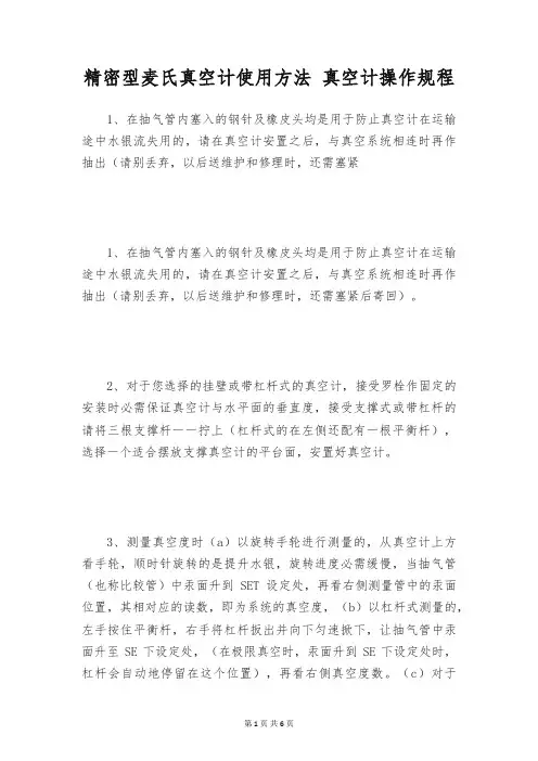
精密型麦氏真空计使用方法真空计操作规程1、在抽气管内塞入的钢针及橡皮头均是用于防止真空计在运输途中水银流失用的,请在真空计安置之后,与真空系统相连时再作抽出(请别丢弃,以后送维护和修理时,还需塞紧1、在抽气管内塞入的钢针及橡皮头均是用于防止真空计在运输途中水银流失用的,请在真空计安置之后,与真空系统相连时再作抽出(请别丢弃,以后送维护和修理时,还需塞紧后寄回)。
2、对于您选择的挂壁或带杠杆式的真空计,接受罗栓作固定的安装时必需保证真空计与水平面的垂直度,接受支撑式或带杠杆的请将三根支撑杆一一拧上(杠杆式的在左侧还配有一根平衡杆),选择一个适合摆放支撑真空计的平台面,安置好真空计。
3、测量真空度时(a)以旋转手轮进行测量的,从真空计上方看手轮,顺时针旋转的是提升水银,旋转进度必需缓慢,当抽气管(也称比较管)中汞面升到SET设定处,再看右侧测量管中的汞面位置,其相对应的读数,即为系统的真空度,(b)以杠杆式测量的,左手按住平衡杆,右手将杠杆扳出并向下匀速掀下,让抽气管中汞面升至SE下设定处,(在极限真空时,汞面升到SE下设定处时,杠杆会自动地停留在这个位置),再看右侧真空度数。
(c)对于PM一6型真空计的读数,低真空的测量方式与a、b两种一样,左侧粗真空的测量方法是让右侧测量管中的汞面升到测量管下端的“0'位线,然后再看左侧比较管中的汞面所对应的读数,即为系统的粗真空度。
4、假如你的被测真空系统达不到5尸a以上的低真空度时,请选择壹台能抽到0.IPa以上的ZX或ZXZ型的真空泵对真空计单独进行一次真空排气,当真空计能显示出5pa的以上真空度数时,再让真空计与被检测的真空系统进行相互联接,若接受真空橡胶管相连的,请将胶管的长度缩短到50公分以内,当然,若真空计与真空系统配套的话,先用中6mm的优质紫铜管与真空计铜接嘴相互焊接,与真空系统之间配置一个可以掌控的阀门,它对真空计的使用寿命来说,会得到更的保障。
麦式真空规转动式安全操作及保养规程摘要麦式真空规是一种常用的测量工具,广泛应用于精密加工领域。
为了保障麦式真空规的正常使用,提高其使用寿命,需要掌握其正确的安全操作和保养规程。
本文阐述了麦式真空规的转动式安全操作及保养规程,希望对相关从业人员提供参考和指导。
1. 麦式真空规转动式安全操作规程1.1 运输前的准备在运输麦式真空规前,需要进行以下准备:1.仔细检查麦式真空规的外观,确认其无损坏和污染。
2.清洁麦式真空规,特别是清洁测量面,以避免由于在运输途中积累的尘土或杂质,影响其测量准确性。
3.使用专业的方法将麦式真空规包装好,以避免在运输途中受损。
1.2 安装调试在安装麦式真空规时,需要注意以下事项:1.确保安装平稳,切勿折弯转动轴,否则会影响精度。
2.在安装时,要规范操作,不得使用滥用力量的方法。
通常需要使用扳手、压板等工具。
在使用这些工具时,一定要注意力量的适度和均匀,以避免在操作过程中,损坏麦式真空规。
3.在安装完毕后,需要仔细检查各部件是否对齐,各螺钉是否紧固牢固,以及转动是否灵活等。
1.3 使用时的注意事项在使用麦式真空规时,需要注意以下问题:1.操作前需检查表面是否干净、转动是否灵活,以及各部件是否正常工作。
2.转动时不得使用外力,否则会影响测量精度。
特别是当发现转动困难时,不得使用力量强行转动。
3.转动角度不宜过大,否则可能在测量时产生阻力影响测量精度。
4.转动过程中,要尽量避免在强光下操作,以免误差产生。
1.4 操作后的注意事项在使用完毕麦式真空规后,需要注意以下事项:1.清洗麦式真空规,并清理测量面和转动轴表面。
2.检查各部件是否出现磨损或松动,如有问题需要及时处理。
3.将麦式真空规装箱,放到指定位置,以避免磨损和损坏。
2. 麦式真空规转动式保养规程为了保养麦式真空规,延长其使用寿命,需要进行以下保养工作:2.1 清洗保养麦式真空规在使用一段时间后,需要进行清洗保养。
具体步骤如下:1.拆卸麦式真空规,将各部件分类整理。