推荐-ISD44语音芯片翻录器设计 精品
- 格式:doc
- 大小:1.37 MB
- 文档页数:46
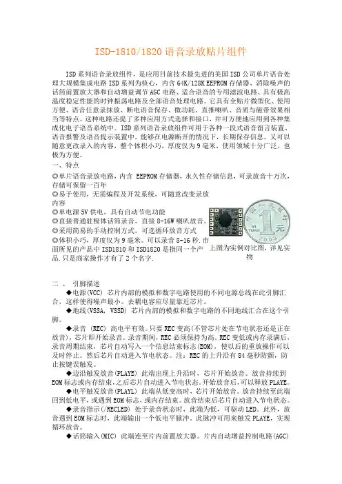
ISD-1810/1820语音录放贴片组件ISD 系列语音录放组件,是应用目前技术最先进的美国ISD 公司单片语音处理大规模集成电路ISD 系列为核心,内含64K/128K EEPROM 存储器、消除噪声的话筒前置放大器和自动增益调节AGC 电路、适合语音的专用滤波电路、具有极高温度稳定性能的时钟振荡电路及全部语音处理电路。
它具有全贴片微型化、使用方便、语音任意录抹放、断电语音保存、微功耗、直推喇叭、音质与磁带效果相当等特点。
这种电路还提了多种应用方式选择和接口,并可方便地应用到各种集成化电子语音系统中。
ISD 系列语音录放组件可用于各种一段式语音留言装置、语音报警及语音提示装置中,能够在电源断开的情况下,长期保存信息,又可以随意更改录入的内容,整个体积小巧,厚度仅为9毫米,使用领域十分广泛,也极为方便。
一、特点◎单片语音录放电路,内含 EEPROM 存储器,永久性存储信息,可录放音十万次,存储可保留一百年◎易于使用,无需编程及开发系统,可随意改变录放内容上图为实例对比图,详见实物 ◎单电源5V 供电,具有自动节电功能◎直接普通驻极体话筒录音,直接8-16W 喇叭放音。
◎采用简易的手动控制方式,可选循环放音方式◎体积小巧,厚度仅为9毫米。
可以录音8-16秒.市面所见的产品中ISD1810和ISD1820是指同一个产品.只是商家操作才有了2个名字.二 、 引脚描述◆电源(VCC) 芯片内部的模拟和数字电路使用的不同电源总线在此引脚汇合,这样使得噪声最小。
去耦电容应尽量靠近芯片。
◆地线(VSSA, VSSD) 芯片内部的模拟和数字电路的不同地线汇合在这个引脚。
◆录音 (REC) 高电平有效。
只要REC 变高(不管芯片处在节电状态还是正在放音),芯片即开始录音。
录音期间,REC 必须保持为高。
REC 变低或内存录满后,录音周期结束,芯片自动写入一个信息结束标志(EOM),使以后的重放操作可以及时停止。
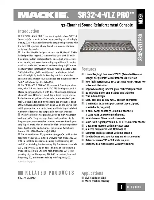
32-Channel Sound Reinforcement ConsoleS R 32•4-V L Z FeaturesLow noise/high headroom XDR™ (Extended DynamicRange) mic preamps with excellent RFI rejectionNew high-performance 2068 op-amps for incredibly low noise and distortionImproved cooling for even greater thermal protection 28 mic/line mono, and 2 stereo line channels True 4-bus designSolo, pan, and 16 kHz Air EQ on each submaster 6 individual aux sends per channel (2 pre, 2 post, 2 switchable pre/post)3-band swept midrange EQ on mic channels; 4-band fixed on stereo line channels 75 Hz low-cut filters on mic channelsMute, solo, signal present and OL LEDs on every channel 6 aux send masters with individual solos 4 stereo aux returns with EFX monitorSeparate Talkback section with mic preampDouble-bused sub outs for easy multi-track routing Balanced stereo TRS & XLR main outputs Balanced XLR mono output with level controlApplicationsLive sound mixing Multi-track recordingIntroductionTHE SR32•4-VLZ PRO is the latest update of our SR32•4sound reinforcement console, incorporating our ultra-high quality XDR™ (Extended Dynamic Range) mic preamps with the best RFI rejection of any sound reinforcement mixer design on the market.Like all of Mackie Designs’ mixers, the SR32•4-VLZ PRO is designed for rugged, 24-hour-a-day use. With its mul-tiple input/output configurations, true 4-bus architecture, 6 aux sends, and extensive routing capabilities, it can be used in a variety of live sound and recording applications. Its sturdy steel construction houses rugged, double-sided SMT-plated fiberglass circuit boards, and 60 mm faders with ultra-tight lip seals for keeping out dust and other contaminants. Impact-resistant knobs are mounted so they “ride” just above the steel chassis.The SR32•4-VLZ PRO has 28 mono mic/line input chan-nels, with XLR mic inputs and 1/4" TRS line inputs, and 2 stereo line input channels with 1/4" TRS inputs. All mono channels have TRS insert jacks (tip = send, ring = return). Each channel strip has an input trim, 6 aux sends (2 pre-fader, 2 post-fader, and 2 switchable pre or post), 3-band EQ with sweepable midrange (4-band EQ on the stereo chan-nels), pan control, and mute, solo, and bus assign switches. A 60 mm fader provides output gain for each channel. Twenty-eight XDR mic preamps provide high-headroom and low-noise. They are impedance-independent, so the frequency response remains constant whether the mic pre-amp is presented with an extremely high- or low-impedance load. Additionally, each channel has its own switchable low-cut filter (18 dB/octave @ 75 Hz).The mono channel EQs provide a range of ±15 dB at the following frequencies: 12 kHz shelving high-frequency EQ, 100 Hz to 8 kHz sweepable peaking mid-frequency EQ, and 80 Hz shelving low-frequency EQ. The stereo channels (21-24) provide ±15 dB of boost and cut at the following frequencies: 12 kHz shelving high-frequency EQ, 3 kHz peaking high-mid frequency EQ, 800 Hz peaking low-mid frequency EQ, and 80 Hz shelving low-frequency EQ.(continued on page 2)R E L A T E D P R O D U C T SSR24•4-VLZ PROCrosstalk(1 kHz @ 0 dBu, 20 Hz to 20 kHz bandwidth, channel in to Main Left outputs):Channel fader down, channels at Unity –89.5 dB Channel muted, channels 2-16 at Unity –88.7 dB Frequency Response(any input to any output):20 Hz to 60 kHz +0/–1dB 10 Hz to 100 kHz+0/–3dB Maximum LevelsMic preamp input +22 dBu All other inputs +22 dBu Balanced XLR outputs+28 dBu All other outputs+22 dBu ImpedancesMic preamp input 1.5 kΩAll other inputs >10 kΩAll outputs120 ΩEqualizationLo EQ Shelving 80 Hz +15 dB Mid EQ (mono ch) Peak 100 Hz-8 kHz +15 dB Hi EQ Shelving 12 kHz +15 dB Microphone PreampE.I.N. (150 Ω terminated, max gain)–129.5 dBm Power Requirements60 wattsPhysicalDimensions (HxWxD): 5.60" x 39.25" x 19.20"142.24 mm x 996.95 mm x 487.68 mm Net Weight: 32•4-VLZ PRO 40.7 lbs (18.8 kg)the left and right mains, 1/4" TRS line outputs for subs 1-4, and an XLR mono main output. The mono main out has its own level control, so a mono mix can be sent to another zone and adjusted accordingly.The Phones/Control Room switch and level control are connected to two stereo headphone outputs and the left and right Control Room output, allowing the stereo Tape Return, Left/Right Main Mix, and Solo to be monitored.A stereo playback device can be monitored via the Tape Return Inputs. Tape Return to Phones/C-R routes the tape playback signal into the monitor system and meters, and the Tape Return knob adjusts the level of playback, which can be monitored via headphones. Tape Return signals can also be assigned directly to the Main Mix. The SR32•4-VLZ PRO also has RCA-style Tape Outs for output to conventional stereo recording devices.Each of the six aux sends has its own individual master send control, driving 1/4" TRS output jacks. Six stereo aux returns are provided, with 1/4" TRS input jacks. Two aux returns can be folded back into Aux Sends 1 and 2 via their own volume controls to add effects in stage monitors.An XLR input is provided for a talkback mic, which can be assigned to the Main Mix or to Aux 1-2. The talkback mic has a level control in the talkback section.SR32•4-VLZ PRO TopSR32•4-VLZ PRO Rear PanelSR32•4-VLZ Pro DimensionsSR32•4-VLZ PRO Block Diagramswitches; and level indicating LEDs. The submix outputs shall each have level, pan, and “air” controls; solo and assign switches; and a bus access insert jack. The main outputs shall share a stereo master output fader and shall be fitted with insert jacks. Additionally, the mixer shall include a pre-fader/post fader solo function, a main monaural output with level control derived from the main stereo outputs, 6 monitor/effects send outputs, 4 stereo effects return inputs with switching and control functions, 1 stereo control room monitor output, 2 stereo headphone outputs, 1 set of stereo tape recorder conve-nience outputs, and 1 set of stereo tape monitor inputs.2. POWER SUPPLY.All necessary operating voltages for the mixer shall be provided by an internal power supply.3. INPUT CHANNEL CONNECTIONS. Each monau-ral channel (1-28) shall include an XDR™ (Extended Dynamic Range) electronically balanced microphone input, using an XLR-3-F-type connector, accepting nominal levels from –60 dBu to +4 dBu via a rotary Trim control. Phantom power shall be globally controlled via a rocker-type switch. Each monaural input channel shall also have an electronically balanced line level input, accommodating a nominal line level of between –10 dBV and +4 dBu, and appearing on the rear panel as a 1/4" TRS phone jack. Each stereo input channel shall have left and right electronically balanced line level input, accommodating a nominal line level of between –10 dBV and +4 dBu, and appearing on the rear panel as 1/4" TRS phone jacks. These jacks shall be fitted with internal switching contacts to accommodate monaural configura-tion. Additionally, each of the monaural input channels (1-28) shall offer an unbalanced insert connection, appearing on the rear panel as a 1/4" TRS phone jack.4. INPUT CHANNEL LEVEL AND ASSIGNMENT CONTROLS AND INDICATORS. Each monaural input chan-nel shall be equipped with a preamplifier gain control,a solo switch, a mute switch, three bus assignment ing equalizer with the knee set at 80 Hz and a range of +15 dB; a low-mid-frequency peaking equalizer centered at 800 Hz and a range of +15 dB; a high-mid-frequency peaking equalizer centered at 3.5 kHz and a range of+15 dB; and a high frequency shelving equalizer with the knee set at 12 kHz and a range of +15 dB.6. INPUT CHANNEL AUXILIARY SENDS. Each mixer input channel shall have 6 monaural auxiliary send con-trols. Two auxiliary send controls shall be fixed as pre-fader sends; two shall be fixed as post-fader sends; and two shall be switchable between pre-fader and post-fad-er. All auxiliary sends shall be post-mute switch.7. MAIN OUTPUT CONNECTIONS. The mixer shall have electronically balanced, line-level left and right main outputs, appearing on male XLR-3 type connectors and impedance balanced on 1/4" phone TRS jacks on the rear panel. Additionally, the main buses shall offer left and right unbalanced insert connections, appearing on the rear panel as 1/4" phone TRS jacks. Further, there shall be a main, electronically balanced, monaural output derived from the main stereo output, appearing as a male XLR-3 type connector on the rear panel. There shall be an output level control to adjust the main monaural output level.8. OTHER OUTPUT AND MONITORING CONNECTIONS. The mixer shall have the following impedance balanced line-level connections, appearing as 1/4" TRS jacks on the rear panel: submix bus outputs 1-4, also wired in parallel respectively to submix outputs 5-8; left and right control room monitor outputs, left and right tape monitor outputs, left and right tape monitor inputs. For conve-nience, the left and right main outputs (unbalanced) and the left and right tape monitor inputs shall also appear as RCA phono jacks on the rear panel. There shall also be two stereo headphone outputs on the rear panel of the mixer, carrying the control room monitor signals at levels and impedances proper for headphones. Each head-phone output connection shall be a stereo 1/4" jack.324 16220 Wood-Red Road NE, Woodinville, WA 98072 USA 888.337.7404,fax425.487.4337,****************Electronic files for this product available at: /installedThis Specification Sheet SR32VLZPRO_SS.PDF Owner/Operator’s Manual SRVLZPRO_OM.PDF CADD files SR32VLZPRO.DXF9. OUTPUT AND MONITORING CONTROLS AND SWITCHES. The mixer shall include one linear fader control for gain adjustment of main L/R outputs, covering a range from infinite attenuation to +10 dB above unity gain. A tape monitor switch shall alternately select either the main L/R outputs or the signal at the tape inputs as the source for the control room and headphones monitoring circuits. There shall be a stereo dual-channel rotary control for gain adjustment of the control room and headphone monitor output. The mixer shall have a stereo dual-channel control for adjustment of the monitoring level of the internal solo signals, and a light to indicate channel solo condition. The solo system shall be capable of switching between PFL (pre-fader listen) and AFL (after-fader listen––solo in place) operation.10. OUTPUT METERING. The mixer frame shall include two 13-segment LED meters each displaying a signal range from –40 dBU to +10 dBu, each with an additional LED indicating mixer clipping level at +22 dBu. The meters shall monitor the main left and right output channels; alternately, the meters shall monitor the tape return sig-nals when the tape monitor switch is depressed; or, the soloed input channel signals when the solo switch is depressed.11. AUXILIARY SEND CONNECTIONS. The mixer shall include impedance balanced, line-level outputs from the six auxiliary send buses, appearing on the rear panel as 1/4" TRS phone jacks.12. AUXILIARY RETURN CONNECTIONS. The mixer shall include 4 stereo auxiliary return inputs. Each auxiliary return shall have a left and a right balanced line-level input, accommodating a nominal line level of between –10 dBu and +4 dBu, and shall appear on the rear panel as 1/4" TRS phone jacks. The jacks shall be fitted with internal switching contacts to accommodate monaural configuration.13. AUXILIARY RETURN CONTROLS AND SWITCHES. The mixer shall include 4 dual-channel auxiliary return gain controls, each feeding the main stereo buses. Auxiliary returns 1-2 shall have their signals assignable to auxiliary send buses 1 and 2, respectively, through rotary level con-trols. Auxiliary return 4 shall be assignable to three differ-ent pairs of destinations, feeding either the main left and right buses or the submix buses.14. PHYSICAL CONFIGURATION. The mixer shall have a steel chassis frame painted grey-black and designed to rest on a horizontal surface. The SR32•4-VLZ PRO’s dimen-sions shall be 6.1" (155mm) high by 39.3" (997mm) wide by 19.2" (487mm) deep.15. SPECIFICATIONS. In addition to specifications previously cited, the mixer shall meet or exceed the fol-lowing specifications. Frequency response, microphone input to any output, 20 kHz to 60 kHz, +0 dB/ –1 dB; Total Harmonic Distortion (THD), any input to any output, 1 kHz @ +14dBu, 0.004%; Equivalent Input Noise (EIN), microphone input to insert send, –129.5 dBm; Common Mode Rejection (CMR), microphone input to insert send, maximum gain, 1 kHz, better than 90 dB; Typical Main Output noise, all channels assigned, odd channels panned left, even channels panned right, all faders down –94.7 dBu; Signal to Noise ratio, ref +4 dBu operating level, 90 dB; Attenuation, ref. 0 dB @ 1 kHz, Main Mix level con-trol down, –85 dBu; Channel Mute engaged, –84 dBu; Channel Gain control down, –83 dBu; Input impedance, microphone inputs, 1.5 k Ω; Channel Insert return, 2.5 k Ω; all other inputs, greater than 10 k Ω; Output impedance, Tape Out, 1.1 k Ω; All other outputs, 120Ω.16. DESIGNATION. The mixer shall be a Mackie Designs SR32•4-VLZ PRO.Mackie Designs continually engages in research related to product improvement. New material, pro-duction methods, and design refinements are introduced into existing products without notice as a routine expression of that philosophy. For this reason, any current Mackie product may differ in some respect from its published description, but will always equal or exceed the original design specifica-tions unless otherwise stated. ©1999–2002 Mackie Designs Inc. All rights Reserved. Mackie and the “Running Man” figure are registered trademarks of Mackie Designs Inc.。
培训资料深圳市艾迪思特信息技术有限公司目录第一章、基本概况了解 (3)一、认识iDste (3)二、iDste产品的型号定义及分类 (3)第二章、iDste智慧校园的主要解决方案 (10)2.1、iDste公司产品解决方案的优势 (10)2.2、iDste智能融合集控物联管理方案 (10)2.3、iDste校园数字广播及集控平台二合一智能融合方案 (14)2.4、iDste校园全数字高清业务、广播系统、远程管理平台三网合一融合系统 (14)2.5、iDste产品销售现场演示环节及销售工具准备 (16)第一章:基本概况了解一、认识iDste1、iDste的中文标准读法及字母所代表的含义中文写法“艾迪思特”读法“ai di si te ”英文字母含义“I do s omething to education”的第一个字母的拼写。
中文意思“我为教育做点事”。
2、iDste品牌的历史、定位及使命iDste品牌注册使用始于2008年,以”iDste”品牌注册的公司成立于2014年。
iDste 成立之初就将自身定位为一个为教育信息化提供优质产品及解决方案的公司,将“为教育做点实事”作为公司的历史使命,通过自身努力及持续创新能力以期成为业界最有责任心、最具专业性的一流企业。
3、iDste目前的产品及解决方案iDste目前具备NC、BC、BW、KC、BS、TM五大系列30多种产品。
解决方案涵盖校园设备集控、数字广播、高清视频信息发布、高保真扩音、多媒体教学等五大核心解决方案。
涉及包含物联网、数字业务融合、移动互联网、工业嵌入式等热点领域。
4、iDste的核心理念“做最负责任的企业、制造最稳定的产品、提供最专业的服务”就是iDste的核心理念。
5、iDste与合作伙伴合作的主体思想“真诚信任的可靠关系、富有激情的进取心、可持续的共赢格局”。
6、iDste产品及解决方案的优势是什么iDste产品本身体现“高品质高度集成+工业嵌入式CPU主核心设计”;解决方案体现“高度数字业务融合”;产品及解决方案体现“硬物联、软物联”的双重特色。
基于89C52单片机的银行自动叫号系统摘要:银行自动叫号系统是为解决排队公平等银行服务问题,提高银行办事效率而设计的智能排队管理系统。
在分析银行排队叫号需求的基础上,基于89c52单片机和isd4004语音芯片设计了银行自动叫号系统,并重点从主机和从机这两个部分探讨了银行自动叫号系统的设计。
关键词:自动叫号系统;银行排队系统;89c52单片机;isd4004语音芯片近年来,各行各业的信息化、智能化建设越来越普及,整个社会对各个行业的办事效率的要求也越来越高。
我国是人口大国,故办不少事情都会遇到”排队”这种令人头痛的问题。
例如像银行办业务,在顾客办业务过程中排队现象在所难免,严重时还常会伴随着如下嘈杂、无序、不公平、不合理、低效等影响银行企业形象的问题。
为了在排队时减少顾客的等待时间,为顾客办业务创造一个良好的环境,银行自动叫号系统应运而生。
本文拟在分析银行排队叫号需求的基础上,从主机和从机这两个方面来探讨基于89c52单片机和isd4004语音芯片的银行自动叫号系统的设计。
[1-3]一、银行自动叫号系统需求分析一般来说,银行自动叫号系统是为解决排队公平等银行服务问题,提高银行办事效率而设计的智能排队管理系统。
银行客户能够通过该系统进行下列活动:(1)客户排号取票。
客户根据需要办理业务的到取票机前依次排号,并获得系统打印的号票。
(2)客户休息等待。
获得系统号票的客户在休息区休息等待,并留意显示屏信息和语音提示。
(3)营业员按钮呼叫。
窗口操作员按”下一位”,窗口显示屏就显示客户的排队号,同时系统播放”请xx号到x号窗口办理业务”之类的语音提示。
(4)客户到窗口办理业务:休息区的客户听到语音提示就到相应窗口进行相关业务服务。
银行自动叫号系统所涉及到的对象活动具体如下:(1)顾客对象的活动。
顾客在取票机的界面上输入选择所需办理的相关业务。
界面将信息传递到控制业务逻辑的对象中心显示屏(动态显示所有等待服务的顾客号码以及相关的业务信息)进行验证,然后传递到窗口显示屏(显示顾客、业务受理员号码及宣传、服务用语)。
⽹友⽤的芯⽚总结⽹友⽤的芯⽚总结(整理版)⽹友在各⾃领域中所⽤到的芯⽚总结1.⾳频pcm编码DA转换芯⽚cirrus logic的cs4344,cs43344334是⽼封装,据说已经停产,4344封装⽐较⼩,⾮常好⽤。
还有菲利谱的。
8211等。
2.⾳频放⼤芯⽚4558,833,此⼆芯⽚都是双运放。
为什么不⽤324等运放个⼈觉得应该是对⾳频的频率响应⽐较好。
3.244和245,由于244是单向a=b的所以只是单向驱动。
⽽245是⽤于数据总线等双向驱动选择。
同时245的封装⾛线⾮常适合数据总线,它按照顺序d7-d0。
4.373和374,地址锁存器,⼀个电平触发,⼀个沿触发。
373⽤在单⽚机p0地址锁存,当然是扩展外部ram的时候⽤到62256。
374有时候也⽤在锁数码管内容显⽰。
5.max232和max202,有些为了节约成本就⽤max202,主要是驱动能⼒的限制。
6.⽹络接⼝变压器。
需要注意差分信号的等长和尽量短的规则。
7.amd29系列的flash,有bottom型和top型,主要区别是loader区域设置在哪⾥?bottom型的在开始地址空间,top型号的在末尾地址空间,我感觉有点反,但实际就是这么命名的。
8.164,它是⼀个串并转换芯⽚,可以把串⾏信号变为并⾏信号,控制数码管显⽰可以⽤到。
9.sdram,ddrram,在设计时候通常会在数据地址总线上加22,33的电阻,据说是为了阻抗匹配,对于这点我理论基础学到过,但实际上没什么深刻理解。
10.⽹卡控制芯⽚ax88796,rtl8019as,dm9000ae当然这些都是⽤在isa总线上的。
11.24位AD:CS5532,LPC2413效果还可以12.仪表运放:ITL114,不过据说功耗有点⼤13、⾳频功放:⼀般⽤LM36814、⾳量控制IC. PT2257/9.15.PCM双向解/编码 ADC/DAC CW669116.2.4G双⼯通讯 RF IC CC250017.cat809,max809,这些是电源监控芯⽚,当低于某⼀电压以后⽐如3.07v等出现⼀个100ms的低电平,实现复位功能。
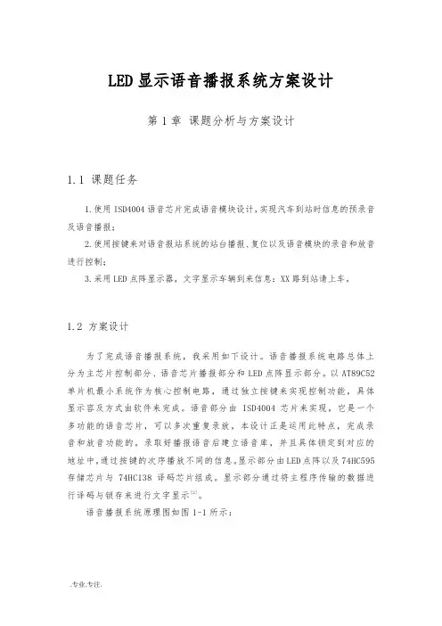
超声波盲人探路仪的设计摘要本文设计一种由74LS04反相器和CX20106搭接电路实现了超声波的发射与接收。
采用超声波发射与接受等技术,设计出盲人外出行走所需要提醒绕过前方障碍物的一种超声波探测器。
只需将超声波盲人探路器安装在盲人的拐杖上,当盲人在走路时前面有障碍物,拐杖上的盲人探路器就会发出报警声,因此起到提示的作用小心绕行。
并能语音播报离障碍物的距离,让盲人能够了解障碍物离自己的距离。
这种超声波盲人探路器使用方便可靠且价格低廉,适合盲人和老人夜间走路,能有效防止事故的发生, 盲人在外出时都会带一根拐杖来探路,以躲避障碍。
由于拐杖不可能太长,探测范围十分有限,利用超声波探测原理组成一个微型探测器并组装在拐杖手柄内,不仅可以提高探测效果和探测距离,而且使用十分方便。
【关键词】89C52 ;单片机;74LS04反相器CX20106电路;超声波的发射与接收;NY3P065AP8;语音芯片THE DESIGN OF THE ULTRASONIC BLIND LIGHTING APPARATUSAbstractIn this paper, the design of a 74LS04 inverter and CX20106 lap circuit achieves ultrasonic transmitter and receiver. Emitting and receiving ultrasonic technology, designed to remind the blind need to walk out in front of obstacles to bypass an ultrasonic detector. Just ultrasonic blind Pathfinder mounted on the blind cane, when there is an obstacle in front of the blind in walking, the blind Pathfinder crutches will sound an alarm on, and therefore play a role in prompting caution bypass. And can voice broadcast from the obstacle distance from obstacles so that blind people can understand their distance. This ultrasonic blind Pathfinder is reliable and easy to use and inexpensive, for the blind and the elderly to walk at night, can effectively prevent the occurrence of the accident, when the blind will go to Pathfinder with a crutch to avoid obstacles. Since crutches not be too long, the detection range is very limited, using ultrasonic detection principle to form a micro-probe and assembled in the cane handle, not only can improve the detection performance and detection range, and easy to use.【Keywords】89C52; SCM; 74LS04 CX20106 inverter circuit; ultrasonic transmitter and receiver; NY3P065AP8; voice chip目录摘要 (I)Abstract.......................................................................................................................................................... I I 目录 ............................................................................................................................................................ - 0 -第1章前言 .................................................................................................................................... - 1 -1.1系统开发背景..................................................................................................................... - 1 -1.2系统开发意义..................................................................................................................... - 1 -1.3设计目的............................................................................................................................. - 1 -第2章系统硬件电路的设计......................................................................................................... - 2 -2.1 主控芯片电路设计.................................................................................................................... - 2 -2.2 超声波测距电路设计................................................................................................................ - 3 -2.2.1 超声波发射电路设计............................................................................................................... - 4 -2.3 语音播报电路的设计.................................................................................................................. - 5 -2.4 蜂鸣器提醒电路的设计............................................................................................................ - 6 -第3章系统软件程序设计............................................................................................................. - 7 -3.1 超声波程序设计.......................................................................................................................... - 8 -3.2 语音播报程序设计...................................................................................................................... - 9 -3.3 蜂鸣器程序设计........................................................................................................................ - 10 -总结 ........................................................................................................................................................ - 11 -参考文献 .................................................................................................................................................. - 12 -附录 A ........................................................................................................................................................ - 0 -附录 B ........................................................................................................................................................ - 0 -致谢 ........................................................................................................................................................ - 5 -第1章前言1.1 系统开发背景蝙蝠能在完全黑暗中,以极快的速度精确地飞翔,从不会同前方的物体相撞,蝙蝠在飞行时,喉内产生并能从通过口腔发出人耳听不到的超声波,当遇到食物或障碍物时,超声波会反射回来,蝙蝠用两耳接受物体的反射波,并据此确定该物体的位置,并可从两耳分别接受到回波间的差别,来辨别物体的远近、形状及性质,蝙蝠在空中能利用超声波来“导航”,就能迅速准确捕捉飞虫。
论文分类号: TP 学校代码: 13681毕业设计说明书(论文)题目: 公交可视化语音自动报站器的设计——主控STC12系列学生姓名:郭 璠 学 号: 2 6 1 1 1 0 2系 部: 信息工程 七系专业班级: 电 信1112班指导教师: 陈明泽 苏 婕二〇一四年四月Automatic Design of Converter Station Bus Visual Speech——MastercontrolSTC12 SeriesABSTRACTIn recent years , with the vigorous development of China's information industry , the standard of living and improve security awareness , people travel for the safety and convenience have created new demand . In addition to the bus-stop system and out of the station bus stop outside , how about to remind passengers to the front of the station names , as well as to those vulnerable groups effectively convey the station information to facilitate their travel , is also an important part of the smart -stop system .The design is mainly to address how easily and accurately instruct passengers arriving problem with the human voice simulation and forecasting stations reporting station , reported on the number of stations and station name and station name for text display and voice message recording station name selection control function. The system includes a microcontroller module , speech synthesis circuit , station number , station name display module , infrared interface circuit , reset circuit and power systems .STC12 microcontroller to control the use of speech synthesis chip and LCD modules . Speech synthesis chip SYN6288 , using simulated data is stored directly patented semiconductor memory technology , the upcoming analog voice data is written directly to a single storage unit , eliminate the need for A/D, D/A conversion , and therefore better able to reproduce the natural effects of real speech avoid the quantization noise and distortion generally solid voice circuits because quantization and compression caused . With LCD display , through the construction of model building simulation systems , access to relevant information related to the sensor and microcontroller combines knowledge , realization station V oice newspaper stand and display (LCD screen ) consisting stop system , give relevant sites , reminding prepare to enter the passenger to get off . Maximize the use of intelligent systems for efficient and convenient travel services , the system will give intelligent people to improve travel efficiency and improve environmental quality , it makes the system more practical newspaper stand .KEY WORDS:Single-chip Microcomputer , Audio Prompt , Bus-Stop Auto-Announce公交可视化语音自动报站器的设计——主控STC12系列摘要近些年来,随着我国信息事业的蓬勃发展,生活水平与安全防范意识的提高,人们对于出行的安全性和便利性都产生了新的需求。
Professional Audio & Video Recorder for Conference TMX-0404SDI24×4 High Definition Digital VideoTracking Matrix SwitcherFeatures■Routing: 4×4 High Definition Digital Video Tracking Matrix Switcher■Video interface: BNC female■Data rates : 143 Mbps~2.97 Gbps■Compatible with SMPTE 259 M, SMPTE 292 M, SMPTE 344 M, SMPTE 424 M and DVB-ASI (270 Mbps)■Input equalization and clock recovery, output pre-emphasis■RS-232 control, supporting RS-232 protocols, for connection with central control system■Two RS-422 control port with built-in professional camera control protocols, a variety of professional cameras like TAIDEN HCS-3316HDB, SONY, PELCO and Panasonic can be controlled■One TAINET interface for connection with TAIDEN conference system■One RJ45 interface for TCP/IP connection■Power-off protection for scene status■LCD to display real-time operation■Front panel button control , easy to switch manually■Front panel keyboard lockup and protection function■Scene save and recall function■1U high, full rack widthTechnical SpecificationsVideoData rates 143 Mbps ~ 2.97 Gbps Data types 8 bit or 10 bit Compatible standards SMPTE 259 M, SMPTE 292 M,SMPTE 344 M, SMPTE 424M,DVB-ASI (270 Mbps) Video inputConnectors 4 × BNC female Input level 0.7 V - 1.2 Vp-p Input cable equalization Typical equalization cable length(RG60/ Ø1.0 mm standard cable)************(oddchannel)************(evenintegerchannel)************* Nominal level 0.8 Vp-p Impedance 75 Ohm Return loss 20~*****************Video outputConnectors 4 × BNC double-decker female Nominal level 0.8 V ± 7% Output level 0.5 V - 1.6 Vp-p Impedance 75 Ohm Return loss >***************** DC offset ± 100 mV with no offset at input Jitter 20~30 ps@HD/3G rate40~60 ps@SD rate Rise and fall time (20~80%) SD: 600 psHD/3G: 100 psControlTo central control system:COM (RS-232) RS-232, 9 pin female D connector COM1 Baudrate: 115200, data: 8 bits, stop: 1 bit, no parity RJ45 TCP/IP TAINET Baudrate: 19200, to main unit RS422 Baudrate: 9600, to dome camera RS232 Baudrate: 9600, to control keypadGeneral specsPower supply AC 100 V - 240 V, 50 Hz / 60 Hz Temperature Operating: 0 °C to + 50 °C;storage: -20 °C to + 70 °C Humidity Storage and operating: 10% to 90% Dimensions h × w ×d (mm) 43 × 483 × 208(1U high, full rack width) Weight 2.7 kg Color Gray (PANTONE 425 C) Mean time between failures 30,000 hoursOrdering InformationTMX-0404SDI2 4×4 High Definition Digital VideoTracking Matrix Switcher (SD/HD/3G)Tracking Matrix SwitcherFeatures■Routing: 8×4 High Definition Digital Video Tracking Matrix Switcher■Video interface: BNC female■Data rates : 143 Mbps~2.97 Gbps■Compatible with SMPTE 259 M, SMPTE 292 M, SMPTE 344 M, SMPTE 424 M and DVB-ASI (270 Mbps)■Input equalization and clock recovery, output pre-emphasis■RS-232 control, supporting RS-232 protocols, for connection with central control system■Two RS-422 control port with built-in professional camera control protocols, a variety of professional cameras like TAIDEN HCS-3316HDB, SONY, PELCO and Panasonic canbe controlled■One TAINET interface for connection with TAIDEN conference system■One RJ45 interface for TCP/IP connection■Power-off protection for scene status■LCD to display real-time operation■Front panel button control , easy to switch manually■Front panel keyboard lockup and protection function■Scene save and recall function■1U high, full rack widthTechnical SpecificationsVideoData rates 143 Mbps ~ 2.97 Gbps Data types 8 bit or 10 bit Compatible standards SMPTE 259 M, SMPTE 292 M,SMPTE 344 M, SMPTE 424M,DVB-ASI (270 Mbps) Connectors 8 × BNC female Input level 0.7 V ~ 1.2 Vp-p Input cable equalization Typical equalization cable length(RG60/ Ø1.0 mm standard cable)************(oddchannel)************(evenintegerchannel)************* Nominal level 0.8 Vp-p Impedance 75 Ohm Returnloss20~*****************Video outputConnectors 4 × BNC double-decker female Nominal level 0.8 V ± 7% Output level 0.5 V ~ 1.6 Vp-p Impedance 75 Ohm Return loss >***************** DC offset ± 100 mV with no offset at input Jitter 20~30 ps@HD/3G rate40~60 ps@SD rate Rise and fall time (20~80%) SD: 600 psHD/3G: 100 psControlTo central control system:COM (RS-232) RS-232, 9 pin female D connector COM1 Baudrate: 115200, data: 8 bits, stop: 1 bit, no parity RJ45 TCP/IP TAINET Baudrate: 19200, to main unit RS422 Baudrate: 9600, to dome camera RS232 Baudrate: 9600, to control keypadGeneral specsPower supply AC 100 V - 240 V, 50 Hz / 60 Hz Temperature Operating: 0 °C to + 50 °C;storage: -20 °C to + 70 °C Humidity Storage and operating: 10% to 90% Dimensions h × w ×d (mm) 43 × 483 × 208(1U high, full rack width) Weight 2.8 kg Color Gray (PANTONE 425 C) Mean time between failures 30,000 hoursOrdering InformationTMX-0804SDI2 8×4 High Definition Digital VideoTracking Matrix Switcher (SD/HD/3G)Tracking Matrix SwitcherFeatures■Routing: 8×8 High Definition Digital Video Tracking Matrix Switcher■Video interface: BNC female■Data rates : 143 Mbps~2.97 Gbps■Compatible with SMPTE 259 M, SMPTE 292 M, SMPTE 344 M, SMPTE 424 M and DVB-ASI (270 Mbps)■Input equalization and clock recovery, output pre-emphasis■RS-232 control, supporting RS-232 protocols, for connection with central control system■Two RS-422 control port with built-in professional camera control protocols, a variety of professional cameras like TAIDEN HCS-3316HDB, SONY, PELCO and Panasonic canbe controlled■One TAINET interface for connection with TAIDEN conference system■One RJ45 interface for TCP/IP connection■Power-off protection for scene status■LCD to display real-time operation■Front panel button control , easy to switch manually■Front panel keyboard lockup and protection function■Scene save and recall function■1U high, full rack widthTechnical SpecificationsVideoData rates 143 Mbps ~ 2.97 Gbps Data types 8 bit or 10 bit Compatible standards SMPTE 259 M, SMPTE 292 M,SMPTE 344 M, SMPTE 424M,DVB-ASI (270 Mbps) Connectors 8 × BNC female Input level 0.7 V ~ 1.2 Vp-p Input cable equalization Typical equalization cable length(RG60/ Ø1.0 mm standard cable)************(oddchannel)************(evenintegerchannel)************* Nominal level 0.8 Vp-p Impedance 75 Ohm Returnloss20~*****************Video outputConnectors 8 × BNC double-decker female Nominal level 0.8 V ± 7% Output level 0.5 V ~ 1.6 Vp-p Impedance 75 Ohm Return loss >***************** DC offset ± 100 mV with no offset at input Jitter 20~30 ps@HD/3G rate40~60 ps@SD rate Rise and fall time (20~80%) SD: 600 psHD/3G: 100 psControlTo central control system:COM (RS-232) RS-232, 9 pin female D connector COM1 Baudrate: 115200, data: 8 bits, stop: 1 bit, no parity RJ45 TCP/IP TAINET Baudrate: 19200, to main unit RS422 Baudrate: 9600, to dome camera RS232 Baudrate: 9600, to control keypadGeneral specsPower supply AC 100 V - 240 V, 50 Hz / 60 Hz Temperature Operating: 0 °C to + 50 °C;storage: -20 °C to + 70 °C Humidity Storage and operating: 10% to 90% Dimensions h × w ×d (mm) 43 × 483 × 208(1U high, full rack width) Weight 3.0 kg Color Gray (PANTONE 425 C) Mean time between failures 30,000 hoursOrdering InformationTMX-0808SDI2 8×8 High Definition Digital VideoTracking Matrix Switcher (SD/HD/3G)TMX-1604SDI216×4 High Definition Digital Video Tracking Matrix SwitcherFeatures■Routing: 16×4 High Definition Digital Video Tracking Matrix Switcher■Video interface: BNC female■Data rates : 143 Mbps~2.97 Gbps■Compatible with SMPTE 259 M, SMPTE 292 M, SMPTE 344 M, SMPTE 424 M and DVB-ASI (270 Mbps)■Input equalization and clock recovery, output pre-emphasis■RS-232 control, supporting RS-232 protocols, for connection with central control system■Two RS-422 control port with built-in professional camera control protocols, a variety of professional cameras like TAIDEN HCS-3316HDB, SONY, PELCO and Panasonic canbe controlled■One TAINET interface for connection with TAIDEN conference system■One RJ45 interface for TCP/IP connection■Power-off protection for scene status■LCD to display real-time operation■Front panel button control , easy to switch manually■Front panel keyboard lockup and protection function■Scene save and recall function■1U high, full rack widthTechnical SpecificationsVideoData rates 143 Mbps ~ 2.97 Gbps Data types 8 bit or 10 bit Compatible standards SMPTE 259 M, SMPTE 292 M,SMPTE 344 M, SMPTE 424M,DVB-ASI (270 Mbps) Video inputConnectors 4 × BNC female Input level 0.7 V - 1.2 Vp-p Input cable equalization Typical equalization cable length(RG60/ Ø1.0 mm standard cable)************(oddchannel)************(evenintegerchannel)************* Nominal level 0.8 Vp-p Impedance 75 Ohm Returnloss20~*****************Video outputConnectors 4 × BNC double-decker female Nominal level 0.8 V ± 7% Output level 0.5 V - 1.6 Vp-p Impedance 75 Ohm Return loss >***************** DC offset ± 100 mV with no offset at input Jitter 20~30 ps@HD/3G rate40~60 ps@SD rate Rise and fall time (20~80%) SD: 600 psHD/3G: 100 psControlTo central control system:COM (RS-232) RS-232, 9 pin female D connector COM1 Baudrate: 115200, data: 8 bits, stop: 1 bit, no parity RJ45 TCP/IP TAINET Baudrate: 19200, to main unit RS422 Baudrate: 9600, to dome camera RS232 Baudrate: 9600, to control cameraGeneral specsPower supply AC 100 V - 240 V, 50 Hz / 60 Hz Temperature Operating: 0 °C to + 50 °C;storage: -20 °C to + 70 °C Humidity Storage and operating: 10% to 90% Dimensions h × w ×d (mm) 43 × 483 × 208(1U high, full rack width) Weight 3.0 kg Color Gray (PANTONE 425 C) Mean time between failures 30,000 hoursOrdering InformationTMX-0404SDI2 16×4 High Definition Digital VideoTracking Matrix Switcher (SD/HD/3G)TMX-1608SDI216×8 High Definition Digital Video Tracking Matrix SwitcherFeatures■Routing: 16×8 High Definition Digital Video Tracking Matrix Switcher■Video interface: BNC female■Data rates : 143 Mbps~2.97 Gbps■Compatible with SMPTE 259 M, SMPTE 292 M, SMPTE 344 M, SMPTE 424 M and DVB-ASI (270 Mbps)■Input equalization and clock recovery, output pre-emphasis■RS-232 control, supporting RS-232 protocols, for connection with central control system■Two RS-422 control port with built-in professional camera control protocols, a variety of professional cameras like TAIDEN HCS-3316HDB, SONY, PELCO and Panasonic canbe controlled■One TAINET interface for connection with TAIDEN conference system■One RJ45 interface for TCP/IP connection■Power-off protection for scene status■LCD to display real-time operation■Front panel button control , easy to switch manually■Front panel keyboard lockup and protection function■Scene save and recall function■1U high, full rack widthTechnical SpecificationsVideoData rates 143 Mbps ~ 2.97 Gbps Data types 8 bit or 10 bit Compatible standards SMPTE 259 M, SMPTE 292 M,SMPTE 344 M, SMPTE 424M,DVB-ASI (270 Mbps) Video inputConnectors 16 × BNC female Input level 0.7 V ~ 1.2 Vp-p Input cable equalization Typical equalization cable length(RG60/ Ø1.0 mm standard cable)************(oddchannel)************(evenintegerchannel)************* Nominal level 0.8 Vp-p Impedance 75 Ohm Returnloss20~*****************Video outputConnectors 8 × BNC double-decker female Nominal level 0.8 V ± 7% Output level 0.5 V ~ 1.6 Vp-p Impedance 75 Ohm Return loss >***************** DC offset ± 100 mV with no offset at input Jitter 20~30 ps@HD/3G rate40~60 ps@SD rate Rise and fall time (20~80%) SD: 600 psHD/3G: 100 psControlTo central control system:COM (RS-232) RS-232, 9 pin female D connector COM1 Baudrate: 115200, data: 8 bits, stop: 1 bit, no parity RJ45 TCP/IP TAINET Baudrate: 19200, to main unit RS422 Baudrate: 9600, to dome camera RS232 Baudrate: 9600, to control keypadGeneral specsPower supply AC 100 V - 240 V, 50 Hz / 60 Hz Temperature Operating: 0 °C to + 50 °C;storage: -20 °C to + 70 °C Humidity Storage and operating: 10% to 90% Dimensions h × w ×d (mm) 43 × 483 × 208(1U high, full rack width) Weight 3.2 kg Color Gray (PANTONE 425 C) Mean time between failures 30,000 hoursOrdering InformationTMX-1608SDI2 16×8 High Definition Digital VideoTracking Matrix Switcher (SD/HD/3G)System Connection。
2008.5系列语音芯片广州唯创科技有限公司地址:广东省广州市天河区棠东东路25号5楼8563855785638637E-mail:***************网址:◎脉冲不可重复触发◎下一曲不循环触发◎非电平保持可循环触发◎上一曲不循环触发◎电平保持不可循环触发◎下一曲可循环触发◎电平保持可循环触发◎上一曲可循环触发5、应用电路及简析设置芯片的各种控制模式、触发模式都可以使用电脑上位机软件和相关下载器简单完成。
⑴、按键控制模式按键控制模式下的应用电路如下图,由K1、K2、K3和K4四个按键控制触发内部存储语音的播放,一个按键能触发一段语音,也能连续的触发多段语音。
按键可以被设置为任何一种触发方式进行触发,电平触发时为低电平触发,脉冲触发时为负脉冲触发。
LED 可以被设置为放音高电平指示或放音低电平指示。
调节内置功放的外反馈电阻R2、R3能调整输出音量的大小。
由Q1、R8、R9和二极管组成上电复位电路,能有效的解决在电压波动大、外干扰信号强等恶劣环境下所造上的上电死机问题。
⑵、并口控制模式并口控制模式下应用电路如下图。
可以用MCU 对WTV 语音芯片进行控制操作,R10~R16为MCU 跟WTV 语音芯片的通讯电压平衡电阻,电阻的计算公式为(Vin-Vout)×700/Vout =Rn。
由MCU 发送地址直接触发WTV 语音芯片内部语音播放,最多可控制128段语音的播放。
1、芯片简介WTV 系列语音芯片是一款功能强大的一次性编程语音芯片,语音为6K 采样频率时,存储长度可分别达到40秒、80秒、170秒、340秒。
音频输出为PWM 或DAC 模式。
可选控制方式有按键控制模式、按键组合控制模式、并口控制模式、串口控制模式等。
按键控制模式的触发方式灵活;串口模式下可控制音量、打开或关闭功放、有循环播放和停止功能。
可应用在汽车防盗报警器、倒车雷达、GPS 导航仪、智能家居系统、家庭防盗报警器、医疗器械人声提示、娱乐设备(游戏机、游乐机)、学习模型(早教机、儿童有声读物)、智能交通设备(收费站、停车场)通信设备(电话交换机、电话机)、工业控制领域(电梯、工业设备)等领域。
关于ISD4004的一些心得ISD系列语音芯片是美国ISD公司推出的产品。
该系列语音芯片采用多电平直接接模拟存储(Chip Corder)专利技术,声音不需要A/D转换和压缩,每个采样值直接存储在片内的闪烁存储器中,没有A/D转换误差,因此能够真实、自然地再现语音、音乐及效果声。
避免了一般固体录音电路量化和压缩造成的量化噪声和金属声。
ISD4004语音芯片采用CMOS技术,内含晶体振荡器、防混叠滤波器、平滑滤波器、自动静噪、音频功率放大器及高密度多电平闪烁存储阵列等(见图1),因此只需很少的外围器件就可构成一个完整的声音录放系统。
芯片设计是基于所有操作由微控制器控制,操作命令通过串行通信接口(SPI或Microwire)送入。
采样频率可为 4.0Hz、5.3Hz、6.4Hz、8.0kHz,频率越低,录放时间越长,而音质则有所下降。
片内信息存于内烁存储器中,可在断电情况下保存100年(典型值)反复录音10万次。
器件工作电压3V,工作电流25~30mA,维持电流1μA?单片录放语音时间8~16min,音质好,适用于移动电话机及其它便携式电子产品中。
1.1 引脚描述ISD4004系列芯片引脚图如图2所示。
二、引脚描述电源:(VCCA,VCCD) 为使噪声最小, 芯片的模拟和数字电路使用不同的电源总线, 并且分别引到外封装的不同管脚上, 模拟和数字电源端最好分别走线, 尽可能在靠近供电端处相连, 而去耦电容应尽量靠近器件。
地线:(VSSA,VSSD) 芯片内部的模拟和数字电路也使用不同的地线。
同相模拟输入(ANA IN+) 这是录音信号的同相输入端。
输入放大器可用单端或差分驱动。
单端输入时,信号由耦合电容输入, 最大幅度为峰峰值32mV, 耦合电容和本端的3KΩ电阻输入阻抗决定了芯片频带的低端截止频率。
差分驱动时, 信号最大幅度为峰峰值16mV,为ISD33000 系列相同。
反相模拟输入(ANA IN-) 差分驱动时, 这是录音信号的反相输入端。
常州信息职业技术学院学生(毕业)设计()题目:ISD4004语音芯片翻录器设计()原创性声明和使用授权说明原创性声明本人郑重承诺:所呈交的(),是我个人在指导教师的指导下进行的研究工作及取得的成果。
尽我所知,除文中特别加以标注和致谢的地方外,不包含其他人或组织已经发表或公布过的研究成果,也不包含我为获得及其它教育机构的学位或学历而使用过的材料。
对本研究提供过帮助和做出过贡献的个人或集体,均已在文中作了明确的说明并表示了谢意。
作者签名:日期: -指导教师签名:日期:使用授权说明本人完全了解大学关于收集、保存、使用()的规定,即:按照学校要求提交()的印刷本和电子版本;学校有权保存()的印刷本和电子版,并提供目录检索与阅览服务;学校可以采用影印、缩印、数字化或其它复制手段保存;在不以赢利为目的前提下,学校可以公布的部分或全部内容。
作者签名:日期:()任务书专业计算机应用技术班级计应041 姓名一、课题名称:ISD4004语音芯片翻录器设计二、主要技术指标:1、项目包含硬件部分与软件部分2、硬件包括:ISD4004读写模块、录放模块、输入模块、功放模块、电源模块。
3、毕业符合规范三、工作内容和要求:1、系统分析、功能模块设计要求: 1) 描述系统应具备的功能;2)画出系统功能分析图3)描述每一模块的功能2、单片机硬件电路设计要求:1)根据系统功能分析的结果画出硬件电路模型图(草图)2) 根据硬件电路模型图画出原理图并布出PCB板,用制板机制出电路板3)在所制的电路上,焊接所需的元器件(同时在万能板上焊上所需的元器件,用于调试电路时用,这样可以减少设计成本)。
3、各功能程序设计要求: 1)跟据用户所需的功能,编写程序(在Keil uVision2编译环境下),主要以C语言为主,嵌入部分汇编语言。
2)思路清晰、各功能模块标明注释4、系统功能调试要求:1)画出实现每一功能的用例图2)设计实现这些功能用到的视图、宏或程序代码5、编著设计要求:1)中应含各项工作内容2)的最后一部分应含设计总结3)满足要求的字数、严禁抄袭四、主要参考文献:1、《Protel 99SE电路设计技术入门与应用》电子工业出版社2、《模拟电子技术》西安电子科技大学出版社3、《单片机高级语言C51Windows环境编程与应用》电子工业出版社学生(签名)年月日指导教师(签名)年月日教研室主任(签名)年月日系主任(签名)年月日()开题报告目录摘要关键词前言一、ISD4004 系列语音录放集成电路应用说明 (6)1、简述 (6)2、引脚描述 (8)3、SPI(串行外部接口) (10)4、时序 (13)5、典型应用电路 (15)6、电气参数 (18)二、低电压音频功放电路 (22)三、电路设计原理图 (28)四、电路设计PCB板 (30)五、源程序代码设计 (31)六、总结 (42)七、谢辞 (42)八、参考文献 (42)ISD4004语音芯片翻录器的研制吴玲玲摘要针对ISD语音芯片的特点,设计一种由单片机控制,能够循环录放的语音电路,可作为录音机,复读机、音频记录仪使用,既节省存储空间,又降低成本,具有较高的实用价值。
关键词:ISD4004 语音循环录放。
SummaryAim at the characteristics of the ISD speech chip, design a kind of from single slice machine control, can circulate to record to putof speech electric circuit be a tape recorder, replying to read machine,the audio frequency record instrument usage, since economical saving space, and then decline low cost, have higher practical value.Keyword:The ISD4004 speeches record to put circularly.前言ISD系列语音芯片是美国ISD公司推出的产品。
该系列语音芯片采用多电平直接接模拟存储(Chip Corder)专利技术,声音不需要A/D转换和压缩,每个采样值直接存储在片内的闪烁存储器中,没有A/D转换误差,因此能够真实、自然地再现语音、音乐及效果声。
避免了一般固体录音电路量化和压缩造成的量化噪声和金属声。
ISD4004语音芯片采用CMOS技术,内含晶体振荡器、防混叠滤波器、平滑滤波器、自动静噪、音频功率及高密度多电平闪烁存储阵列等,因此只需很少的外围器件就可构成一个完整的声音录放系统。
芯片设计是基于所有操作由微控制器控制,操作命令通过串行通信接口(SPI或Microwire)送入。
采样频率可为4.0Hz、5.3Hz、6.4Hz、8.0kHz,频率越低,录放时间越长,而音质则有所下降。
片内信息存于内烁存储器中,可在断电情况下保存100年(典型值)反复录音10万次。
器件工作电压3V,工作电流25~30mA,维持电流1μA?单片录放语音时间8~16min,音质好,适用于移动电话机及其它便携式电子产品中。
目前,市场上的固体录音机及各种录音笔,大多采用的是顺序录音,不具备循环录音功能,一旦存储器录满,必须重新操作才行。
本文设计一种能够循环录放的语音电路,即可解、上述问题。
一、ISD4004 系列语音录放集成电路应用说明1、简述◆单片8至16分钟语音录放、8、10、12及16分钟◆3V单电源工作◆工作电流2530mA,维持电流1uA◆高质量、自然的语音还原技术◆自动静噪功能◆无需开发系统◆内置微控制器串行通信接口◆多段信息处理◆不耗电保存信息100年(典型值)◆100000次录音周期(典型值)◆片内免调整时钟,可选用外部时钟ISD4004-10M 10分钟 6.4KHz 2.7KHz 2400 250ms 819.2KHz ISD4004-12M 12分钟 5.3KHz 2.3KHz 2400 300ms 682.7KHz ISD4004-16M 16分钟 4.0KHz 1.7KHz 2400 400ms 512KHzFigure: ISD4003 Series Black DiagramISD4004系列TSOP及PDIP、SOIC引脚如下:(和ISD4003系列相同)Figure 1: ISD4004 Series TSOP and PDIP/SOIC Pin outsISD4004系列工作电压3V,单片录放语音时间8至16分钟,音质好,适用于移动电话机及其它便携式电子产品中。
芯片采用CMOS技术,内含振荡器、防混清滤波器、平滑滤波器、自动静噪、音频放大器及高密度多电平闪烁存贮陈列。
芯片设计是基于所有操作由微控制器控制,操作命令通过串行通信接口(SPI或Micro wire)送入。
芯片采用多电平直接模拟量存贮技术,每个采样值直接存贮在片内的闪烁存贮器中,因此能够非常真实、自然地再现语音,音乐、音调和效果声,避免了一般固体录音电路固置化和压缩造成的量化噪声和多属声。
采样频率可为4.0,5.3,6.4,8.0KHz,频率越低,录放时间越长,而音质则有所下降,片内信息存于闪烁存贮器中,可在断电情况下保存100年(典型值)反复录音10万次。
2、引脚描述电源(VCCA,VCCD)为使噪声最小,芯片的模拟和数字电路使用不同的电源总线,并分别引到外封装的不同引脚上,模拟和数字电源端最好分别走线,尽可能靠近供电源处相连,而去耦电容应尽量靠近器件。
地线(VSSA,VSSD)芯片内的模拟和数字电路也使用不同的地线。
几个VSSA 尽量在引脚焊盘上相连,并用低阻通路连到电源上,VSSD也用低阻通路连到电源上。
这些接地通路要足以使VSSA与VSSD之间的阻值小于3Ω。
芯片的背面是通过衬底电阻连接到VSS的,在做COB时托盘须接VSS或悬空。
同相模拟输入(ANAIN+)这是录音信号的同相输入端。
输入放大器可用单端或差分驱动。
单端输入时,信号由耦合电容输入,最大幅度为峰峰值32mV,耦合电容和本端的3KΩ电阻输入阻挠决定了芯片频率的低端截止频率。
在差分驱动时,信号最大幅度为峰峰值16mV。
这两种戏动方式见下图反相模拟输入(ANAIN-)差分驱动时,这是录音信号的反相输入端。
信号通过耦合电容输入,最大幅度为峰峰值16mV,本端的标称输入阻挠为56kΩ,单端驱动时,本端通过电容接地。
两种方式下,ANAIN+和ANAIN-端的耦合电容值应相同。
音频输出(AUDOUT)提供音频输出,可驱动5KΩ的负载。
片选(SS)此端为低,即选中ISD4003B系列串行输入(MOSI)此为串行输入端,主控制器应在串行时钟上升沿之前半个周期将数据放到本端,供TER输入串行输出(MISO)TER串行输出端,TER末选中时,本端呈高阻态。
串行时钟(SELK)TER的时钟输入端,由主控制器产生,用于同步MOSI和MISO的数据传输。
数据在SCLK上升沿锁存到TER,在下降沿移出TER。
忠断(INI)本端为漏极开路输出,TER在任何操作(包括快进)中检测到EOM或OVF时,本端变低并保持。
中断状态在下一个SPI周期开始清除,中断状态也可用RITN指令读取。
OVF标志指示TER录放操作已到达存贮器的末尾。
EOM标志只在放音过程中检测到内部的EOM标志时,此状态位置1。
行地址时钟(RAC)漏极开始输出。
每个RAC周期表示TER存贮器的操作进行了一行(TE63480系列中的存贮器其2400行)。
8KHz采样频率的器件,RAC周期为200ms,其中175ms保持高电平。
低电平为25ms。
快进模式下,RAC218.75us 高电平,31.25us为低电平,该端可用于存贮管理技术外部时钟(XCLK)本端有内部下拉元件,芯片内部的采样时钟在出厂前已调校,误差在+1%内,商业级芯片在整个温度和电压范围内,频率变化在+2.25%内.工业级芯片在整个温度和电压范围内,频率变化为-6%+4%,此时建议使用稳压电源.若要求更高精度,可从本端输入外部时钟(如前表中所列).由于内部的防混淆及平滑滤波器已设定,故上述推荐的时钟频率不应改变。
输入时钏的占空比无关紧要,因内部首先进行了分频,在不外接时钟时,此端必须接地。
自动静噪(AMACP)当录音信号电平下降到内部设定的某一阈值以下时,1MF电容,构成内部信号电平峰值检测电路的一部分。
检测出的峰值电平为内部设定的阈值作比较,决定自动静噪功能的翻转点,大信号时自动静噪电路不衰减,静音时衰减6dB,1uF电容也影响自动静噪电路时信号幅度的响应速度,本端接VCCA则禁止自动静噪。