Focusview画框幕尺寸数据
- 格式:doc
- 大小:38.00 KB
- 文档页数:1

jcrop 参数jcrop是一个基于jQuery的图片裁剪插件,通过设置参数可以实现不同的裁剪效果。
以下是jcrop插件常用的参数:1. aspectRatio: 设置裁剪框的宽高比,可以是数字或者是一个数组。
例如:aspectRatio: 1 表示裁剪框的宽高比为1:1。
2. minSize: 设置裁剪框的最小尺寸,可以是一个数组,例如:minSize: [100, 100] 表示裁剪框的最小宽度为100px,最小高度为100px。
3. maxSize: 设置裁剪框的最大尺寸,可以是一个数组,例如:maxSize: [500, 500] 表示裁剪框的最大宽度为500px,最大高度为500px。
4. setSelect: 设置默认的选中区域,可以是一个数组,例如:setSelect: [100, 100, 300, 300] 表示默认选中区域的左上角坐标为(100, 100),宽度为300px,高度为300px。
5. onSelect: 当选中区域发生变化时触发的回调函数,可以在该函数中进行一些操作,例如实时显示选中区域的坐标、宽度和高度等。
6. onChange: 当选中区域发生变化时触发的回调函数,与onSelect类似,但是onChange会频繁触发,而onSelect只在选中区域变化时触发一次。
7. onSelectChange: 当选中区域发生变化时触发的回调函数,与onChange类似,但是onSelectChange只在鼠标释放时触发一次。
8. allowSelect: 是否允许新建选中区域,默认为true。
9. allowResize: 是否允许调整选中区域的大小,默认为true。
10. allowMove: 是否允许移动选中区域,默认为true。
以上是jcrop插件的一些常用参数,具体可以根据自己的需求进行设置和调整。
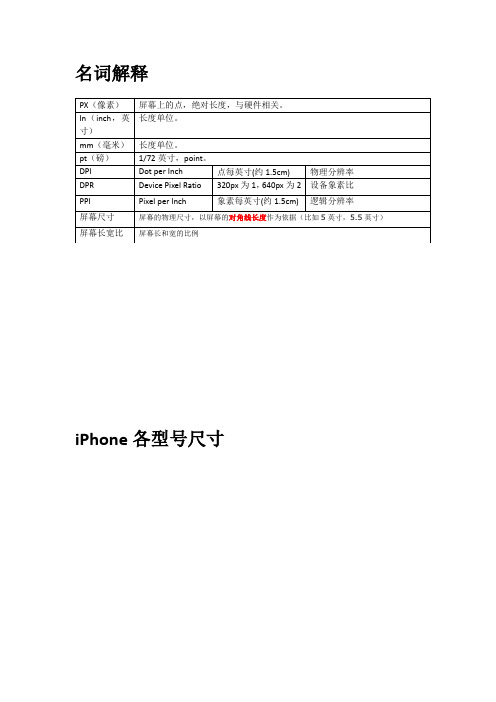
名词解释iPhone各型号尺寸上图中的红字“display zoom”即为放大模式(老人模式),upsampling和downsampling意为宽度的缩放倍数IOS APP UI设计尺寸IOS APP UI设计,图片命名规则设计APP时,所有图片需要保存为PNG格式,如果是高清版本,需要将放大版的图片前缀加上@2x,iPhone6 Plus需要加@3x前缀Viewport(可视区)viewport可视区示意图上图中绿色部份为viewport(上图为iPhone3GS 默认的viewport)上图中橙色部份为viewport,不作任何设置,默认将为980px宽(逻辑分辨率)上图为对viewport进行了一系列设置,且进行了放大1.5倍后的可视区上图是PC网页在手机中浏览的情况,阴影部份为320大小,看起来是不是很不适合?使用meta标签对viewport进行设置(设置数值)效果如上图(左:设置前;右:设置后)使用meta标签对viewport进行设置(设置为设备宽)注:这里的device不应翻译为设备;devide-width 将会使用移动设备的默认逻辑分辨率来呈现页面,即最上面第一张图表中的第一行“象素”尺寸。
iPhone3GS 效果如上图(左:设置前;右:设置后),舒服了很多?注:iPhone3GS默认逻辑分辨率为320px宽,所以右图显示宽为320px。
其它viewport参数:width: 屏幕逻辑宽度initial-scale: 默认缩放倍数maximum-scale: 最大缩放倍数minimum-scale:最小缩放倍数user-scalable:用户是否可以对页面进行缩放js获取默认逻辑分辨率的方法:或者使用更详细的方法,见下例:移动端设备Viewport取值Git: https:///JacksonTian/1202575其它移动web的meta标签iPhone私有标签,实现页面全屏浏览顺带一提Android的全屏用如下代码实现iPhone私有标签,指定iPhone中safari顶端的状态条的样式;告诉设备忽略将页面中的数字识别为电话号码去除Android平台中对邮箱地址的识别禁止safari对页面中5位数字的自动识别和自动添加样式,或者也可以通用css设置去掉手机点击链接的绿框-webkit-tap-highlight-color改写iOS Safari中可点击元素的高亮颜色。
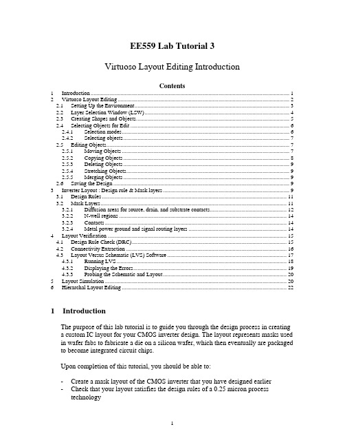
EE559 Lab Tutorial 3Virtuoso Layout Editing IntroductionContents1Introduction (1)2Virtuoso Layout Editing (2)2.1Setting Up the Environment (3)2.2Layer Selection Window (LSW) (4)2.3Creating Shapes and Objects (5)2.4Selecting Objects for Edit (6)2.4.1Selection modes (6)2.4.2Selecting objects (7)2.5Editing Objects (7)2.5.1Moving Objects (7)2.5.2Copying Objects (8)2.5.3Deleting Objects (9)2.5.4Stretching Objects (9)2.5.5Merging Objects (9)2.6Saving the Design (9)3Inverter Layout : Design rule & Mask layers (9)3.1Design Rules (11)3.2Mask Layers (11)3.2.1Diffusion areas for source, drain, and substrate contacts (12)3.2.2N-well regions (14)3.2.3Contacts (14)3.2.4Metal power ground and signal routing layers (14)4Layout Verification (15)4.1Design Rule Check (DRC) (15)4.2Connectivity Extraction (16)4.3Layout Versus Schematic (LVS) Software (17)4.3.1Running LVS (18)4.3.2Displaying the Errors (19)4.3.3Probing the Schematic and Layout (20)5Layout Simulation (20)6Hierarchal Layout Editing (22)1IntroductionThe purpose of this lab tutorial is to guide you through the design process in creatinga custom IC layout for your CMOS inverter design. The layout represents masks usedin wafer fabs to fabricate a die on a silicon wafer, which then eventually are packaged to become integrated circuit chips.Upon completion of this tutorial, you should be able to:-Create a mask layout of the CMOS inverter that you have designed earlier-Check that your layout satisfies the design rules of a 0.25 micron process technology-Check that your layout passes the automatic verification against that inverter schematic created earlier-Extract a netlist including parasitic resistances and capacitances from the layout -Simulate the netlist using HSPICE or Nanosim, and compare results to schematic simulations done earlier•The format of this tutorial is not providing step by step instruction to complete the layout design and verification but it contains enough explanations to help you tofinish the basic design work.•More information about the layout tool can be found in the online documentation under the Layout Editor (cdsdoc command).•For the evaluation, you need to generate DRC/LVS error free layout of inverter and InverterTest design and do the layout simulationsuccessfully. When you do the layout simulation, use the input signal pattern that you used in the schematic simulation.2Virtuoso Layout Editing•Before you begin running the layout editor, copy the display.drf file from the /package/eda/cells/tsmc025/ directory to your home directory •To start up the Virtuoso Layout Editor, enter layoutPlus in a UNIX window prompt (note the uppercase “P”). You can also use icfb instead oflayoutPlus. The Main difference is that layoutPlus doesn’t provide thesimulation functionality.•When the CIW appears, select File -› New -› Cellview. Similarly, you can use the Library Manager to create new cellviews. In the new window that appears, setLibrary Name to tutorial and type in inverter as the Cell Name. In the ViewName field, type in layout and press the tab key. The Tool field should change to Virtuoso. Click OK to continue.•Two windows will appear. One is called the Layer Selection Window (LSW). The LSW allows you to choose the layer on which you create objects, set which layers are selectable and set layer visibility. Note that the technology file that youentered in the first tutorial (cmosp25) defines the layers and colors that will beavailable to you in the LSW.•The other window is the layout window (Virtuoso Layout Editing) where you perform the place and route of the inverter layout.2.1 Setting Up the EnvironmentBefore you start doing your layout, you need to setup the grid size of the cellview so that each grid will correspond to a dimension that will make the layout process easier and allow for a more compact design.•To set up the display environment, select Options -› Display. The Display Option window will appear. In the window, change Minor Spacing to 0.06 and MajorSpacing to 0.30. Change both X Snap Spacing and Y Snap Spacing to 0.02.•Leave other settings at their default setting. However, take note that those options will allow you to change the display of the cellview if need arises. Please refer to the online documentation if you need further information.•The settings can be saved and loaded back using the Save To and Load From buttons at the bottom of the window. You can choose to save or load settings toeither the cellview, library of the cellview, technology of the cellview, or aspecified file. If you are saving to a file, the settings from both the Layout Editor Options and Display Options windows will be saved. Click OK when done.•Back in the layout window, select Options -› Layout Editor. The Layout Editor Option window will appear. Options here allow you to change the editingcommands of the editor and change how the cursor behaves.•In the Layout Editor Option window, uncheck the Gravity On box. This will prevent the cursor from being “attracted” to other objects already drawn in thecellview. Experiment on your own. If you feel that you are comfortable with this function or find it useful in certain situations, you can turn it on. Click OK when done.2.2 Layer Selection Window (LSW)The Layer Selection Window (LSW) lets you to choose the layer on which you create objects (called the entry layer). It also controls which layers are selectable or visible.•To change the LSW to make layers selectable or visible, move the cursor over the layer and click using the middle button. It will toggle layer visibility and alsoautomatically sets invisible layers to be unselectable. The text layer colordisappears to show the layer is invisible. The layer name turns gray to show thelayer is not selectable.•Every time after you have selected the layer, select Window -› Redraw to see the effect of any LSW changes that you have made. This will allow you to makeseveral changes in the LSW before taking time to redraw the cellview, especially in complex designs.•To make the layers visible, click on the AV (All Visible) button. The colored squares showing the layer color reappear, and the shading on the layer namedisappears.•Use the left mouse button to select layers for entry in the LSW. The abbreviation dg after each layer name means drawing (pn means pin).2.3 Creating Shapes and ObjectsMost of the layers that you will draw will be rectangles or polygons that arerectilinear in shape. The sizes of the objects depend on the design and the design rules.Creating rectangles•To create rectangles, select a layer (for example, metal1/dg) from the LSW, then select Create -› Rectangle or click the Rectangle icon on the left. In the newwindow that appears, type the net name you want the rectangle to be associatedwith. You can choose to leave it blank and name the net later. Shortkey forcreating rectangles is ‘r’•Note that assigning names to the nets aid in the future layout verification processes. However, ensure that the net names on the layout matches the ones inthe schematic, otherwise the LVS program (refer to section 4.3) will fail to match the nets.•Point and click on the first corner of the rectangle, then point to the opposite corner of the rectangle (follow the prompt in the layout window and CIW).Creating polygons•Another way of creating objects is to create polygons. Select a layer from the LSW, then select Create -› Polygon or click the Polygon icon on the left. In thenew window that appears, type the net name you want the polygon to beassociated with. You can choose to leave it blank and name the net later. Set Snap Mode to orthogonal. The snap mode controls the way segments snap to thedrawing grid as you create the polygon by placing its vertices.•Point and click on the first point of the polygon. The CIW will prompt for the second point of the polygon. Move the cursor to click on a second point. Thelayout editor will create a solid line parallel to either the Y-axis or the X-axis.Continue to click on a third point that is orthogonal to the solid line. The layouteditor will create two solid lines at right angles to each other between the pointsyou entered. You will also see two dashed lines at right angles to each otherattached to the two points you entered. The dashed lines show how the layouteditor would finish the polygon if you click twice on this point you entered.•If you made a mistake in one of the points while creating the polygon, you can hit the Backspace key to undo them in order.Creating Pins•In order to perform layout verification after the layout is completed (refer to section 4.0), pins must be created to match the schematic.•To create pins, select Create -› Pin. In the window that appears, change the Mode to shape pin. A new window named Create Shape Pin will replace the previouswindow.•Enter the pin net name in the Terminal Names field. Make sure that the names exactly match the schematic (case sensitive). If you are not sure about the names of the pin nets, open the schematic and check the net properties.•Turn on the Display Pin Name option if you would like the pin names to be displayed on the layout cellview. Click the Display Pin Name Option button tochange the display properties of the pin names (size, font, direction etc.).•Select the I/O Type accordingly. For power and ground pins, select inputOutput.•Select the layer in the LSW (use the layer that has the pn abbreviation) and draw the pin in the cellview by clicking on one corner of the pin, followed by thesecond corner.•If you have chosen to display the pin name in the cellview, after you have placed the second corner of the pin, the pin name will appear next to cursor. Move thecursor to where you want the pin name placed and click.2.4 Selecting Objects for Edit2.4.1 Selection modesTo edit an object, first you need to select it. There are two selection modes: full and partial. Press the F4 key to toggle between selection modes and the mode is displayed in the status banner of the layout window (top).•In full selection mode (default), you select the entire object when it is clicked.When in full mode, the status banner will display:(F) Select: 0•In partial selection mode, you can select the entire object or just edge or corner of an object. When in partial mode, the status banner will display:(P) Select: 02.4.2 Selecting objects•To select an object, set the selection mode and click the object.•To deselect all objects, click in an empty part of the design.•To select one or several objects at a time, press the Shift key while selecting.•To deselect one or several objects after they have been selected, press the Ctrl key and select.2.5 Editing ObjectsThere are several functions that are commonly used to edit objects. They include: move, copy, delete, stretch and merge. Should you require more advanced editing methods, please refer to the Editing Objects section in the Virtuoso Layout Editor User Guide.2.5.1 Moving Objects•To move an object, change to full selection mode and select the object(s). Notice that when you move the cursor within the selected object, the pointer changes tofour arrows. This indicates that the object(s) can be moved by clicking anddragging.•Alternatively, you can choose to select Edit -› Move from the drop down menu or use the Move icon on the left. The Move window appears. After you have selectedthe object(s), the CIW will prompt you for a reference point (start point) for themove. Click on the reference point for the move, and drag the pointer to thedestination point. The object will be moved with respect to the reference point.•Note that in the Move window, there is a Change To Layer option. This will allow you to move and change the object from one layer to another without having toredraw the object. Check the box to enable the Change To Layer function andmove the object as usual.•You can rotate or flip the object (sideways or upside down) by clicking the Rotate, Sideways and Upside Down buttons in the Move window before placing the object. You can also do the same by using the right click on the mouse afteryou have selected the reference point for the move. Shortkey for move function is ‘m’.2.5.2 Copying Objects•To copy an object, select Edit -› Copy or use the Copy icon after you have selected the object(s). After the copy window appears, select the object(s) to becopied. The CIW will prompt you for a reference point (start point) for the copy.Click on the reference point for the copy, and drag the pointer to the destinationpoint. The object will be copied with respect to the reference point. Shortkey forcopy function is ‘c’.•To copy and paste multiple copies of the object, type in the number of copies in either the Rows or Columns fields and place the objects in the cellview as usual.•To copy and paste an array of copied objects, enter both rows and columns. The CIW will prompt you to place the first object of the array. After you have placedthe first object, continue to place the second column of the array. The distancebetween the first object and the second will determine the spacing and orientation between the rest of the columns. After you have placed the columns, click to place the rows of the array and complete the array. Similarly, the distance between thefirst and second rows will determine the spacing and orientation between the rest of the rows.•Note that in the Copy window, there is a Change To Layer option. This will allow you to copy and change the object from one layer to another without having toredraw the object. Check the box to enable the Change To Layer function andcopy the object as usual.•You can rotate or flip the object (sideways or upside down) by clicking the Rotate, Sideways and Upside Down buttons in the Copy window before placingthe object. You can also do the same by using the right click on the mouse afteryou have selected the reference point for the move2.5.3 Deleting Objects•To delete an object, change to full selection mode and select the object(s). Select Edit -› Delete or press the Delete key.2.5.4 Stretching Objects•To stretch an object, switch to partial selection mode and select the object(s) at its corners and edges. Notice that when you move the cursor within the selectedobject, the pointer changes to an arrow pointing to a line. This indicates that theobject(s) can be stretched at the corners or edges by clicking and dragging.•Alternatively, you can choose to select Edit -› Stretch from the drop down menu or use the Stretch icon on the left. The Stretch window appears. Leave the LockAngles option on unless you need to form nonorthogonal shapes. After you haveselected the edge(s) to be stretched, the CIW will prompt you for a reference point (start point) for the stretch. Click on the reference point for the stretch, and dragthe pointer to the destination point. The object will be stretched with respect to the reference point. Shortkey for stretch function is ‘s’.2.5.5 Merging Objects•You can use the merge function to merge two objects of the same layer. To merge objects, select the objects to be merged, then select Edit -› Merge.2.6 Saving the Design•To save the design, select Design -› Save or click the Save icon on the left.3 Inverter Layout : Design rule & Mask layersThe pictures in this section present an inverter layout very similar to the one you are about to create. The only significant difference should be the transistor widths. The inverter you create should have transistor widths matching the values you determined in tutorial 1.This layout is in the style of standard cells used for automated placement and routing of random logic. This does not, however, mean that this style of layout is bad for custom layout. It has some very useful features. In particular,•It is designed so that multiple instances of the cell can be connected together by abutment (i.e., placed immediately to the left and right of each other). The power, ground, input, and output connections line up and will be connected. Of course, you may wish to have the input and output not line up so that you can have the power and ground connections connect up without necessarily connecting the input and output together.•The layout lends itself to a left to right signal flow in the metal layer (used for the input and output) as well as vertical signal flow for short distances in polysilicon. •If other types of logic cells have the same layout spacing between power and ground, then cells of various types can be chained together easily.3.1 Design Rules•Design rules are a set of rules (usually supplied by the manufacturer) that specifya minimum size or spacing requirements between layers of the same type or ofdifferent types. This provides a safety margin for various process variations, toensure that your design will still have reasonable performance after your circuit is fabricated.•Note that the technology file you specified in the first tutorial (cmosp25) defines the design rules that will be used to check your design. It also defines how thedrawing layers are translated into masks for the IC. The design rule file used isdivaDRC.rul.•The following section will discuss about the more common design rules. For other design rules, they can be found in the T-025-MM-DR-002.pdf file in the/package/eda/cells/tsmc025 directory.3.2 Mask LayersThe mask layers are the various layers shown in the above diagram and are used to define the location and size of the devices and nets. Each layer can be treated as an individual layer meaning that two different layers have no electrical connectionbetween them even though they happen to overlap. The layers are typically indifferent colors and shading (displayed in the Layer Selection Window – refer tosection 3.2) and are defined by the display.drf file.3.2.1 Diffusion areas for source, drain, and substrate contacts•Rectangles on the active layer are used to define the region where doping is to be applied (except under the polysilicon gate) to form the source and drain of eachtransistor. For an NMOS transistor, the doping will be n+. For a PMOS transistor, this doping will be p+. It will be shown later how the type of doping is actuallyspecified.•Rectangles on the poly1 layer are used to define the strips of polysilicon used to form the gate of each transistor and to provide short distance connections between transistors in the inverter.•The intersection of an active and poly1 region defines the channel of a transistor.Since the minimum size of active is 0.30μ and poly1 is 0.24μ, this means that the minimum transistor width must be 0.30μ and the minimum length must be 0.24μ.•Note that in some cases, it may not be possible to draw an active area as a simple rectangle. The area may have to be one width at the source and drain toaccommodate the required clearance around source and drain contacts. It thenmay need to be notched to obtain the necessary transistor width for theintersection with poly1.•The active layer is also used to define regions that must be doped to allow a bulk (substrate or well) contact. In p- substrate, the doping must be p+ type. In an N-well (where PMOS transistors are placed), the doping must be n+ type. Note that there are square active layers in the above inverter layout example to form thebulk contacts.•Rectangles on the nplus and pplus layers are used to control the type of dopant applied to each diffusion area. Note that these areas must extend past the diffusion area (active) by at least 0.26μ.Figure 3.3. NMOS and PMOS transistorsFigure 3.4. N-well contact for PMOSFigure 3.5. P-substrate contact for NMOS3.2.2 N-well regions•PMOS transistors must be located in substrate with N type doping. The substrate for the PMOS transistors is formed by diffusing N type dopant into regions of the normally p- type substrate. Rectangles in the nwell layer define these regions inwhich PMOS transistors can be placed.3.2.3 Contacts•0.30μ x 0.30μ squares drawn on the contact layer will cause metal plugs to be placed into contact with the diffusion areas to form source, drain, and substrate or well contacts.•0.30μ x 0.30μ squares drawn on the contact layer will cause metal plugs to be placed into contact with the poly1 areas to form poly contacts.•Metal placed on layer metal1 will connect with these contacts.3.2.4 Metal power ground and signal routing layers•Rectangles on the metal1 layer define regions of aluminum to be placed in the first metal layer. In this case metal1 is used for all inputs and outputs to theinverter.• A 0.30μ x 0.30μ square on contact provides a metal plug to connect routing on layer metal1 to polysilicon routing below on the poly1 layer.•In the 0.24μ TSMC process, there are several other metal layers available (metal2, metal3 and so on). We are not going to use it in this layout since it is not needed. However, in larger more complex layouts, both layers will be needed.Often it is a wise practice to route all signals horizontally on one layer andvertically on another layer.•To connect the metal1 layer to the metal2 layer, a square on via12 is used.•You can connect other metal layers together using the appropriate via layers. For example, to connect the metal2 layer to the metal3 layer, a square on via23 isused.4 Layout VerificationAfter you have completed the layout, you need to perform several verificationprocedures to ensure that the layout does not violate any design rules and doesactually correspond with the schematic design that you have made earlier.4.1 Design Rule Check (DRC)DRC checks your layout against physical design rules defined in the divaDRC.rul file. It will display error information if it finds any part in the layout that violates the design rules. Note that this is only a physical design check and does not verify the actual performance or functionality of the layout design.•To run DRC, select Verify -› DRC from the drop down menu. Check that the Rules file and the Rules library fields are correct in the DRC window. Click OKto start.•If there are any errors, it will be reported in the CIW. A blinking polygon, called an error marker, appears in the cellview at the location of the error.•To view the errors and get a brief description of the error, select Verify-> Markers -› Explain and click on any error marker. The marker will behighlighted in yellow to indicate that it is selected. A window named marker textwill appear that contains information about the cellview that contains the errorand the rule that was violated.•To quit the Explain command, press the Esc key.•To remove the markers, select Verify -› Markers-› Delete All. The Delete All Markers window appears. Click OK to remove the markers.•If any errors are reported, make changes to the layout and re-run DRC until all errors have been fixed.•For large complex designs, it is possible to run an incremental DRC. This means that the system will keep track of any changes you made since the last DRC and it will check only the changes made. This will make DRC run faster as it does nothave to re-check every part of the design.•To turn on incremental DRC, set the Checking Limit to incremental in the DRC window.•It is also possible to run a DRC on a specific area. To do this, set the Checking Limit to area in the DRC window, and click on the Sel by Cursor button. Selectthe area on the cellview that you want a DRC to be performed on by clicking onthe first point of the rectangle followed by the second point. The coordinates ofthe points will be entered.4.2 Connectivity ExtractionBefore performing a Layout Versus Schematic (LVS) check, you need to extract the connectivity form the layout cellview by running the Extract program. The Extract program uses rules defined in the technology file to recognize devices and establish electrical connections or nets. It will create an extracted cellview that shows the nets.•To run the Extract program, select Verify -› Extract.•In the Extractor window, select flat as the Extract Method. A flat extract method is used because parasitic capacitance values can vary between different instances of the same cell, thus each cell must be extracted.•Turn on Join Nets With Same Name. This will merge nets with the same names while suppressing warning messages about different nets that have the samename.•To select the types of parasitics that are to be extracted, click the Set Switches button in the Extractor window. In the Set Switches window that appears, selectthe type of parasitics that are to be extracted (typically parasitic capacitances).Click OK when done selecting.•Click OK or Apply in the Extractor window to create the extracted views.•The extraction rules appear in the CIW as the extract program executes. When the extraction is complete, a message saying that the extracted cellview is saved will be shown.•To view the extracted cellview, select File -› Open from the CIW. It should be under the same library and cell name. Select the extracted view name and clickOK.•The extracted cellview appears on top of the layout cellview. Notice that the extracted cellview is similar to the layout, but the gates now have symbols at one end. Displayed next to the symbols are the gate width and length.•To display the electrical connections, open the Display Options window and select Nets. Click Apply when done.4.3 Layout Versus Schematic (LVS) SoftwareAs its name implies, the LVS program performs a comparison of the schematic to the physical layout. It will use both the extracted view and the schematic view of the layout. If you did not create an extracted view, LVS will not work.4.3.1 Running LVS•To run LVS, select Verify -› LVS.•If a LVS Form Contents Different window appears, click OK to continue.•In the LVS window, fill in the schematic and extracted fields either with the Browse or Sel by Cursor button. If you choose to use the Sel by Cursor button, click on the button, then simply click in any area of the schematic or extractedcellview window.•Note that if both the schematic and extracted cellview are opened before the LVS window, the fields should already be filled automatically. Check to ensure thatthey are correct.•Make sure that the specified Rules File is divaLVS.rul and the Rules Library is cmosp25.•Turn off the Correspondence File option. The purpose of the correspondence file is to allow the user to identify schematic/layout nodes that should be mappedto each other. Mainly you would do this if LVS has trouble matchingthe schematic and layout on its own.•Click Run to start LVS. When the Save Cellview window appears, click OK to save. The LVS job runs in the background and might take a couple of minutes to complete, depending on the complexity of the design. When the job is finished, a dialog box named Analysis Job Succeeded will appear. Note that this only meansthat the LVS program was executed successfully and does not mean that thelayout matches the schematic.•To view the LVS results, click Output in the LVS window. A text window listing the output from the LVS run appears. Scroll down until the section that compares the layout and schematic is displayed. In that section, it will report whether thetwo designs match and provide a list of the numbers of instances and nets.If LVS verifies that the layout matches the schematic, it will report:The net-lists matchOtherwise, it would report:The net-lists failed to match•If the layout fails to match the schematic, the errors on the layout must be corrected.4.3.2 Displaying the Errors•Make sure that the extracted cellview is opened before you continue.•To display the errors, click the Error Display button at the bottom of the LVS window.•In the LVS Error Display window that appears, click the First button in the Display field. The error message will be displayed below the Display field. Inaddition, the geometries in the extracted layout that do not match anything in the schematic will be highlighted in a color specified in the Error Color field.•You can check the Auto Zoom option to zoom to the error. To clear the markers, click on the Clear Display button in the LVS Error Display window.。

干货:小白必知的UI界面尺寸规范一、UI尺寸基础知识1、像素密度-PPI像素密度是指显示屏幕每英寸的长度上排列的像素点数量,PPI(Pixels per inch)越高代表屏幕显示效果越精细,Retina屏比普通屏清晰很多,就是因为它的像素密度翻了一倍。
2、计量单位iOS和Android平台都定义了各自的像素计量单位。
iOS的尺寸单位为pt,Android的尺寸单位为dp。
说实话,两者其实是一回事。
单位之间的换算关系随倍率变化:1倍:1pt=1dp=1px(mdpi、iPhone 3gs)1.5倍:1pt=1dp=1.5px(hdpi)2倍:1pt=1dp=2px(xhdpi、iPhone 4s/5/6)3倍:1pt=1dp=3px(xxhdpi、iPhone 6)4倍:1pt=1dp=4px(xxxhdpi)单位决定了我们的思考方式。
在设计和开发过程中,应该尽量使用逻辑像素尺寸来思考界面。
设计Android应用时,有的设计师喜欢把画布设为1080×1920,有的喜欢设成720×1280。
给出的界面元素尺寸就不统一了。
Android的最小点击区域尺寸是48x48dp,这就意味着在xhdpi的设备上,按钮尺寸至少是96x96px。
而在xxhdpi设备上,则是144x144px。
无论画布设成多大,我们设计的是基准倍率的界面样式,而且开发人员需要的单位都是逻辑像素。
所以为了保证准确高效的沟通,双方都需要以逻辑像素尺寸来描述和理解界面,无论是在标注图还是在日常沟通中。
不要再说“底部标签栏的高度是96像素,我是按照xhdpi做的”这样的话了。
下面我们通过列表看下UI界面尺寸规范,记得收藏新手设计师为什么要对线性图标Say NoUI设计师必备的Mockup网址插画为什么能在UI中这么火?。

显示屏像素参数及最佳视距计算各种类型显示屏的最小单元板和单元板模组点数参数表类型规格/显示基色/(¢是点直径,p是点间距)室内最小单元板/室外箱体尺寸最小单元板分辨率备注(格密度)¢3.0=p4.0mm单色¢3.75=p4.75mm单色¢5.0=p7.62mm单色¢3.0=p4mm双色¢3.75=p4.75mm双色¢5.0=p7.62mm双色p5mm间距全彩p6mm间距全彩p7.62mm间距全彩p10mm间距全彩256mm×128mm304mm×152mm484mm×242mm256mm×128mm304mm×152mm484mm×242mm160mm×80mm192mm×96mm320mm×160mm64×3264×3264×3264×3264×3264×3232×1632×3232×1632×1616×816×816×816×816×816×816×816×862500点/平方44321点/平方17222点/平方62500点/平方44321点/平方17222点/平方40000点/平方27800点/平方17222点/平方10000点/平方10000点/平方6944点/平方3096点/平方10000点/平方6944点/平方3096点/平方6944点/平方3096点/平方2500点/平方室内244mm×122mm32×16p10mm单红色(单色)320mm×160mmp12mm两红色(单色)p16mm两红色(单色)室外192mm×96mm256m×168mmp10mm红绿色(双色)320mm×160mmp12mm红绿色(双色)192mm×96mmp16mm红绿色(双色)256m×128mmp12mm(2r+1b+1g)(全彩)p16mm(2r+1b+1g)(全彩)p20mm(2r+1b+1g)(全彩)192mm×96mm256mm×128mm320mm×160mm488mm×244mm320mm×160mm半户外p7.62单红色p10单红色64×32门楣屏17222点/平方32×16门楣屏10000点/平方led显示屏可视距离的计算方法:RGB混色距离三种颜色混合成一种颜色的距离:LED全彩屏幕观看距离=像素间距(mm)×500/1000最小的观看距离能显示平滑图像的距离:LED显示屏可视距离=像素间距(mm)×1000/1000最合适的观看距离观看者能看到高度清晰画面的距离:led显示屏最佳视距=像素点间距(mm)×3000/1000最远视距:LED显示屏最远视距=屏幕高度(m)×30(次)。

投影幕布最佳观看距离2011-12-25 10:35:08| 分类:技术文档|举报|字号订阅画面H 480级720级1080级3H(米)4H(米)5H(米)32 39.84 2.82 1.88 1.25 1.20 1.59 1.99 37 46.07 3.26 2.18 1.45 1.38 1.84 2.30 40 49.80 3.53 2.35 1.57 1.49 1.99 2.49 42 52.29 3.70 2.47 1.65 1.57 2.09 2.6146 57.27 4.06 2.70 1.80 1.72 2.29 2.8647 58.52 4.14 2.76 1.84 1.76 2.34 2.9350 62.25 4.41 2.94 1.96 1.87 2.49 3.1152 64.74 4.59 3.06 2.04 1.94 2.59 3.2455 68.48 4.85 3.23 2.16 2.05 2.74 3.4256 69.72 4.94 3.29 2.19 2.09 2.79 3.4957 70.97 5.03 3.35 2.23 2.13 2.84 3.5560 74.70 5.29 3.53 2.35 2.24 2.99 3.7465 80.93 5.73 3.82 2.55 2.43 3.24 4.0570 87.15 6.17 4.12 2.74 2.61 3.49 4.3680 99.60 7.06 4.70 3.14 2.99 3.98 4.98100 124.50 8.82 5.88 3.92 3.74 4.98 6.23103 128.24 9.08 6.06 4.04 3.85 5.13 6.41110 136.95 9.70 6.47 4.31 4.11 5.48 6.85120 149.40 10.58 7.06 4.70 4.48 5.98 7.47130 161.85 11.46 7.64 5.10 4.86 6.47 8.09150 186.75 13.32 8.82 5.88 5.60 7.47 9.34200 249.00 17.64 11.76 7.84 7.47 9.96 12.45各种屏幕的尺寸(高,宽)H A32 40 7137 46 8240 50 8942 52 9346 57 10247 59 10450 62 11152 65 11555 68 12256 70 12457 71 12660 75 13365 81 14470 87 15580 100 177100 125 221103 128 228110 137 243120 149 266130 162 288150 187 332200 249 443高清推荐尺寸全高清推荐尺寸36度视角推荐尺寸1.5米26英寸37英寸46、47英寸2.0米37英寸56英寸60、65英寸2.5米40英寸60、65英寸72英寸3.0米50英寸76英寸90英寸3.5米60英寸90英寸120英寸以上4.0米70英寸120英寸最小投射距离(米) = 最小焦距(米)x 画面尺寸(英寸)÷ 液晶片尺寸(英寸)最大投射距离(米) = 最大焦距(米)x 画面尺寸(英寸)÷ 液晶片尺寸(英寸)已知投射距离得到画面尺寸最大投射画面(米) = 投射距离(米)x 液晶片尺寸(英寸)÷ 最小焦距(米)最小投射画面(米) = 投射距离(米)x 液晶片尺寸(英寸)÷ 最大焦距(米)例如:1、Toshiba TLP-S71的焦距是26.5mm~31.5mm, 液晶片尺寸是0.7英寸LCD板,需要85英寸的画面。
一、16:9比例幕布计算方法:长= 对角线X 0.8716宽= 对角线X 0.4903例:100寸幕,长= 100 X 0.8716 = 87.16英寸= 87.16 X 2.54 = 221.39 (cm)宽= 100 X 0.4903 = 49.03英寸= 49.03 X 2.54 = 124.54 (cm)二、4:3比例幕布计算方法:长= 对角线X 0.8宽= 对角线X 0.6300”投影幕(4:3)=6096*4572mm120”投影幕(4:3)=2440*1830mm投影的距离=投影机幕布的宽X投影机镜头的焦距由公式套出:投影机幕布宽=投影距离÷投影机镜头的焦距投影机镜头的焦距=投影距离÷投影机幕布宽举个例子:松下FD570投影机要在10米的距离投100寸的话求应该用哪个投影机镜头我们可以这样算 10(米)÷2.03(米)=4.9261084(这个就是投影机镜头的焦距)由此可以得出需要的镜头是ET-DLE300 (变焦长距离3.7-5.7:1)以下这些镜头是适用于松下FD系列的投影机上的ET-DLE050 定焦短距镜(0.8:1)ET-DLE100 变焦短距镜(1.3-1.8:1)ET-DLE200 变焦长距离(2.5-4.0:1)ET-DLE300 变焦长距离(3.7-5.7:1)ET-DLE400 变焦长距离(5.7-8.0:1)标准镜头 1.8~2.5F是镜头的透光度。
F越小,镜头的透光性越好。
f是镜头的放大比率。
如,f=1.4时,就是说,在一固定的位置上,画面可放大1.4倍。
镜头的光圈是用数值来表示的,一般从1.6-2.0,为使用方便,一个镜头设置多档光圈,光圈的数值越大,光圈就越小,光通量也越少,每一个镜头的最大光圈都用数值标在镜头的前方。
焦距也是用数值来表示的,通常从50-210,分为短焦、标准和长焦,还有超短和超长焦的。
数值越小焦距越短,数值越大焦距越长,投影机对镜头焦距的要求正投一般在50-140,背投一般在35左右,焦距决定了打满预定尺寸时投影机与影幕的距离,焦距越短,投影机与影幕的距离就越近,反之就越远。
Humanics ErgoSystems, Inc.Specialists in ErgonomicsCertificant, Board of Certification of Professional ErgonomistsE RGONOMICS R EVIEWErgonomics of seated movementA review of the scientific literatureConsiderations relevant to the Sum ™ chairwritten for Allsteelby Rani Lueder, CPEHumanics ErgoSystems, Inc.June 1, 2004From Corlett and Eklund (1984) How does a backrest work?Graphic used with permission. .. .. .. ..T able of ContentsERGONOMICS AND THE SUM (1)Summary (1)Overview (1)We need to move (2)Not moving is harmful (2)... and contributes to backpain and injury. (4)... as well as leg swelling (edema) (5)Yet all movements are not the same (6)Unsupported sitting (7)Forward-oriented movements (8)Twisting / rotation / bending movements (9)Sitting and seating (12)What happens when we sit? (12)Relaxed sitting flattens (flexes) our lumbar spine (12)”Dynamic” backrests promote continuous support (15)Unsupported sitting (upright) (16)Support forward and back movements from centered positions (17)Reclined sitting (relaxed) (17)Conclusions (19)Acknowledgement (19)References (20)About Rani Lueder, CPE (30)Ergonomics and the SumSummaryOver the last two decades, our focus has gradually shifted from Array identifying the best single sitting posture towards a moredynamic view of sitting and movement.While this emphasis on movement has helped avoid ergonomicrisk factors, it also confused the issues. Movement is critical,but it is not the only consideration. Taken to extremes, a strictemphasis on movement may even introduce new risk factors.Movements are not the same; we ought to avoid some movements. This paperdescribes research relevant to movement and its implications for sitting and seating. These research dimensions include:1. Why movement is so important.2. Why different movements are not equal.3. Selected seat design considerations.OverviewAs in all fields of science, our assumptions about sitting reflect changing paradigms inthe research that shape the questions we ask and how we interpret its findings.For most of the last century, ergonomists widely assumed that we should sit upright (Staffel, 1884; Hooton, 1945; Akerblom, 1954). This emphasis on what Dainoff (1994) described as the “cubist posture” (with 90° knee, torso and elbow positions) aimed to prevent ergonomic risk factors that lead to discomfort and health disorders.The late 1980’s saw a recognition that office work is more hazardous than had beenbelieved – and that constrained sitting postures can cause health disorders,particularly when other risk factors are present (e.g., NIOSH, 1997).While movement is critical, this emphasis on movement for its own sake sometimes takes extremes. The drumbeat that “we need to move” has heralded new products that may contribute to awkward, unstable and unsupported postures. At times, health professionals also worsen the situation by maintaining that awkward and unstable postures are fine if users change positions from anything, to anything.This is not to downplay the importance of movement. Movement is essential. Rather, the aim of this paper is to revisit these assumptions.We need to moveWe have long known that constrained sitting is bad for our health (s.f., Adams and Hutton, 1983; Duncan and Ferguson, 1974; Eklund, 1967; Graf et. al, 1995; Hunting, et. al, 1980 and 1981; Hult, 1954; Langdon, 1965; NIOSH, 1997).In 1777, Ramazzini described hazards of constrained sitting among writers: “Now 'tis certain that constant sitting produces Obstructions of the Viscera,especially of the Liver and Spleen, Crudities of the Stomach, a Torper of theLeggs, a languid Motion of the refluent Blood and Cacbexies. In a word, Writersare depriv'd of all the Advantages arising from moderate and salutary Exercise.” More recently, a report by the National Institute of Occupational Safety and Health (NIOSH, 1997) summarized research demonstrating a relationship between awkwardand constrained postures and musculoskeletal disorders.Constrained postures increase discomfort and health risks (s.f. the review by Aaras et al, 1997). Videman et al. (I990) found that both sedentary work and heavy physical work were associated with abnormalities of the spine1, but the relationship was particularly strong for sedentary work such as in the office.Static seating postures cause discomfort. Graf et al. (1993, 1995) reported more discomfort and chronic disorders among workers who sit in fixed postures. Movement reduces these risks (Aaras et al, 1997; Kilbom, 1987).It is difficult for us to tolerate unsupported and static seated postures for more than a short while (Reinecke et. al., 1985). When allowed to move freely, people are usually in constant motion (Branton, 1967, 1969; Jurgens 1980). Sitters tend to cycle through postures over the day (Bhatnager et al, 1985; Branton and Grayson, 1967; Fleischer et al, 1987). People tend to develop unique patterns of seated movements (Fleischer et al, 1987; Jurgens, 1980; Ortiz et al, 1997) - which Fleischer (1987) compared to individual handwriting styles2.Unfortunately, intensive computer work diminishes opportunities to change postures and move (Grieco, 1986; Waersted and Westgaard, 1997).Not moving is harmful1 These researchers studied disc degeneration in 86 cadavers. They described abnormalities such as disc degeneration, end-plate defects and osteoarthrosis of the facet joints of the vertebra.2 That is, “as a sequence of actions thought to be produced by an internalized specification of commands that indicates which muscles shall act at what time and what intensity”.We have long known that constrained sitting is uncomfortable. Static postures contribute to a broad range of chronic disorders (e.g., Hunting et al., 1981) that include joint impairments such as arthritis, inflamed tendons and tendon sheaths, chronic joint degeneration (arthroses), muscle pain (Grandjean, 1987), impaired circulation and tissue damage (Kilbom, 1986).direct proportion to the muscle loads (Grandjean, 1987).Muscle oxygenation reduces with fairly low loads3(McGilland Hughson, 2000). At sixty percent of maximum force(e.g., working with elevated arms), blood flow is virtuallyoccluded (Grandjean, 1987).Static postures reduce our effectiveness4, causing us tomove more often5, (Bhatnager et al6, 1985; Fenety et al,2000; Jurgens, 1980) and to move into postures(Bhatnager et al, 1985) that we know to be harmful(Andersson, 1980; Andersson et al, 1974a, 1975, 1986;Bhatnager et al, 1985).Some researchers maintain that such damaging effectsare more related to a "lack of physical variation" than inactivity (Bendix 1994; Winkel and Oxenburgh, 1990). That is, the actual lack of variety of postures is more hazardous than the sedentary nature of the work.3 These researchers found a reduction in tissue oxygenation of the lumbar extensor muscles with as little as 2% of Maximum Voluntary Contraction (MVC).4 Bhatnager et al (1985) reported that the percentage of errors increased from less than 2% to more than 8% over the three hours’ of sitting, which they attributed to less effective scanningpatterns. Between the best and worst workplace conditions, performance increased from about4% to about 6% errors. They wrote, “subjects appeared to realize that their performance was getting worse and increased their stopping times in an (unsuccessful) effort to compensate.”5 Such as by fidgeting.6 Bhatnager et al (1985) wrote, “The frequency and severity of body part discomfort increased with time on task, as did frequency of postural changes... Frequency of postural changed increased by more than 50% over the three hours and such appear to be a sensitive indicator of postural stress.”… and contributes to backpain and injuryMore than seventy percent ofpeople older than 40 experienceintermittent back pain. Our sittinghabits affect our risk of back pain(e.g., Bendix 1994; Kelsey 1975b).Kelsey (1975b) found that sittingmore than half the time at work wasassociated with herniated discs inthose older than 35.People often assume that back painis caused by short-term (acute)events such as accidents. Yetthough slips and falls certainlyinjure, research suggests long-term(low-level) chronic stressors are atleast as important.That is, fixed postures are as likely tolead to disabling back pain as heavymanual work such as construction.Constrained postures can causechronic degenerative alterations ofthe cervical, thoracic, and lumbo-sacral areas of the spine (Graf et. al.1995; Hunting et. al., 1980; Occipinti et.al., 1987; Polus et. al., 1985).commonly sit in static positions for long periods, are likely to develop very high levels of intervertebral disk immobility (Wood and McLeich, 1974). One reason that it is so important to move is that after the age of ten, our spine loses its ability to actively feed itself(or, rather, feed the inter-vertebral discs of the spine) andThe herniated lumbar spine, from two directions (Slavin and Raja, 2001) Progression of disc herniation (Bendix, 1994)eliminate waste products (Adams and Hutton, 1983; Grandjean, 1987; Maroudas, et al, 1975; Schoberth, 1978). After this age, the spine receives nutrients and eliminates wastes through passive changes in osmosis resulting from movement.Faiks and Reinecke wrote “there is scientific evidence that prolonged static sitting may compromise spinal structures by reducing disk nutrition, restricting capillary blood flow, and increasing muscle fatigue.”Adams (1996) reported that people with severely degenerated discs had more extensive disc innervation than “normal” people.… as well as leg swelling (edema)Leg swelling (edema) is caused by “an increase in net transcapillary filtration, which exceeds the removal of fluids by the lymphatics” (Van Array Deursen et al, 2000).Leg swelling (edema) is common. Widmer (1986)interviewed 4,529 workers, finding that 70% ofwomen and 44% of men reported this discomfort.The American Public Health Association (APHA,2003) indicates that between 200,000 and 600,000Americans will suffer from deep-vein thrombosis(DVT) and pulmonary embolism each year.They note:Deep-vein thrombosis occurs when a thrombus forms … in one of the largeveins, usually in the lower limbs, leading to either partially or completelyblocked circulation. The condition may result in health complications…Pulmonary embolism can occur when a fragment of a blood clot breaks loosefrom the wall of the vein and migrates to the lungs, where it blocks a pulmonaryartery or one of its branches. When that clot is large enough to completelyblock one or more vessels that supply the lungs with blood, it can result insudden death.Leg swelling causes more than cold feet. Local pooling of blood increases venous pressures to the heart, blood pressure and heart rate. It predisposes users to venous disorders such as varicose veins (Kilbom 1986; van Deursen 2000c).Lack of movement is strongly associated with leg swelling(Van Deursen et al, 2000)7; Winkel 1981; Winkel and Jorgensen, 1986). During movement, muscles expand and contract,thereby promoting circulation. It can also be fatal (APHA, 2003; Beasley et al, 2003). Thelatter described a case in which a 32 year-old maledeveloped life-threatening venous thromboembolism fromsedentary work.When users move about in their seat, their foot swellingimproves (Sherman and Hedge, 2003; van Deursen et al, 2000c;Winkel and Jorgenson, 1986) Van Deursen (2000c) reported that incorporating small butcontinuous movements into the day increased the time ofonset of leg swelling. Not surprisingly, intermittent exerciseis also effective (Winkel, 1981).Y et all movements are not the sameThe overall forces acting on the spine are less important than the concentration of forces acting on the discs, ligaments and related spinal structures (Dolan and Adams, 2001) and the susceptibility of these structures to damage.The associated risk also varies considerably between people. Compressive loads and displacement of force are affected by our age and the degeneration of the spine (e.g., Pollintine et al, 2004).Dolan and Adams (2001) add, “tissue stress probably plays a major role in determining if a given tissue is painful, it is tissue stress rather than overall loading which influences the metabolism of connective tissue cells”.We know that repetitive movements can be hazardous(NIOSH, 1997). Repeated cycles of movements resemble the effects of static postures (e.g., Kumar, 2004).Unsupported sittinglong. Most people would rather slump than performthe muscle work needed to sit upright.Leaning against a backrest reduces both intradiscalpressures in the spine and loads at the back portion ofthe spine8(Rohlmann et al, 2001). Array Several things happen when we maintainunsupported postures – even when there ismovement. Of particular importance, we tend toslump forward, reversing the lumbar curve (lumbarkyphosis) (Bridger and Eisenhart-Rothe, 1989)If users are fit, their abdominal muscles may helpstabilize postures (Corlett and Eklund, 1984) althoughthis is not fully agreed on (Kumar, 2004). Even so, fitor not, postural support shifts from the muscles to theligaments that support the spine. Ligaments deform,increasing risk of spine and joint injury.This is particularly important in today’s officesbecause most office employees work most of theirday with their back unsupported by their backrest(e.g., Dowell et al, 2001).8 That is, at the fixator loads involving the facet joints, articular surfaces close to individual vertebralbodies (bones).Forward-oriented movementsSitting in static positions leads to smallmovements in our chair that we often refer to as“fidgeting” (Bhatnager et al, 1985; Fenety et al,2000). That is, as we become uncomfortable wetend to move, perhaps to compensate forreduced effectiveness at work.Further, this tendency to fidget with time isassociated with a tendency towards forwardoriented (anterior) movements and postures thatincrease loads on the spine and soft tissues 9(Andersson, 1980; Andersson et al, 1974a, 1975,1986; Bhatnager et al, 1985; Rohlmann et al, 2001;Wilke et al, 1999). In fact, loads on the spine (intra-discal pressures) are almost twice as high when flexing forward relative to unsupported sitting – and almost three times higher than relaxed sitting (Wilke et al, 1999). Others reported that leaning forwards (flexion) dramatically increases intradiscal pressures as well (Andersson et al, 1974a, 1975; Rohlmann et al., 2001).Forward-leaning postures also increase risk of disc rupture because the posterior segment of the disc lacks the strength to withstand these loads – even when intradiscal pressures are low 10 (Adams et al, 1994). The posterior longitudinal ligaments are considerably thinner than the anterior (front) ligaments. Further, theshould not surprise us. Long-term static sitting work is very demanding… muscle work and other physical loads become difficult to sustain, particularly given that static postures impair circulation. It becomes increasingly difficult to perform the muscle work needed to “sit properly”.Forward leaning postures introduce risk factors, but users do not mind because they do not have to work their muscles as hard while their ligaments hold their spine in position.Of course, other factors may also contribute to this tendency to lean forwards with time. For example, the visual demands of the task and the reach distances can also play a role. 10 These researchers noted that serious disc failure is closely associated with what is called the “moment arm” of forces associated with forward bending – even when the compressive loads on the spine are not particularly high. They add, “Conversely, if the bending moment is small or absent, no amount of compression can damage the soft tissues before the vertebrae”.fibrous tissues that surrounds the intervertebral discs11 are not equivalent – forward (anterior) postures are much more likely to cause tearing.Fleischer (1987) emphasized the importance of designing chairs that promote movements that we recognize as beneficial - particularly between shifts between upright and reclined sitting (as opposed to shits toward forward-leaning postures). Twisting / rotation / bending movementsTwisting is unique to human beings. We are Array fortunate to be able to do so; it would otherwisebe difficult for us to function (Kumar, 2004).Kumar (2001) described spinal rotation as “adestabilizating motion for an inherently unstablestructure”.Much of this unpredictability relates to the factthat twisting typically involves a combination ofrotation, forward / back and sideways (lateral)movements that are difficult for us to predict andcontrol for any particular situation.Further, combined movements along these three planes interact with each other when we twist. Combined movements are problematic in a variety of ways. Movement along one plane typically diminishes the available range of movement along other dimensions (Evjenth and Hamberg, 1984).Twisting movements along the forward (anterior) plane is particularly compromising. Combined movements that lock the facet joints12 at the back end of the spine introduce a different sort of risk.Risk also increases when natural movements of individual segments are constrained. Evjenth and Hamberg (1984) wrote the following:First, because the vertebral column consists of many articulating segments,movements are complex and usually involve several segments. This also means that restrictions may be complex. For instance, if a single segment is restricted, the adjacent segments may assume part of its normal tasks in executingmovement. Thus, hypomobility and forced hypermobility may both exist in arelatively short section of the spine.11 This fibro-cartilaginous tissue of the intervertebral discs is called the annulus fibrosus.12 Each facet joint represents two opposing bony surfaces separated by cartilage and surrounded by a capsule.Second, because the spinal cord runs along thechannel formed by the vertebral column, damage toor excessive movement of the column is potentiallyhazardous to the nervous system.Twisting is also complicated by the direction of twistingof its different components that sometimes worktogether and at other times are at odds with each other(Evjenth and Hamberg, 1984) Twisting (axial rotation of the spine) increases risk of injury (Au et al, 2001; Kumar et al., 1998; Kumar, 2001), in part from the increased compressive loads on the spine (Au et al, 2001). Yet compression is only part of the equation. Kumar described how prolonged and extreme twistingdamage joints. First, heightened loads increase theforces acting on the joints, deform connective tissuesand ultimately destabilize the joints.With time, as muscles fatigue and joints weaken, the resulting imbalance can lead to unnatural and uncoordinated movements at the joints that cause injury.Research suggests that extremely small rotations (less than 2° per vertebral segment) are not harmful and may even benefit users 13 (Van Deursen et al, 2001).Such micro-movements correspond to the natural / free range of motion of the individual motion segments that make up the spine 14.Minute rotary movements 15 in one’s chair may lessen back plain and reduce forces acting on the lumbar spine from improved disc nutrition (Lengsfeld et al, 2000b).Yet our spine enables us to twist considerably farther than the 2° to 3° in natural range of motion lumbar segments– actually (when including motion of each of thesegments). Kumar (1996, 2004) reported as much as 70° of twisting (axial rotation) for the entire spine. Kumar (2004) described the massive body of research demonstrating a very strong relationship between twisting and back injury 16. Some suggest that as little as 20° of13 This laboratory study by Van Deursen et al (2001) used pig cadavers. These findings appear to be confounded because they removed the facet joints (segments towards the back of vertebra) and related spinal components. Even so, these researchers maintained that this did not affect results as the range of rotation was within the joint’s free inter-space range of movement. 14Punjabi and White (2001) suggest the natural range may be closer to 3°.15 These researchers used one patient diagnosed with degenerative instability of the lumbar spine. The rotational movements of the chair were 1.2° to the right and left, at a frequency of .22 Hz.twist involving across the mid-back may greatly increase the risk of disc herniation. Kumar described a number of possible mechanisms for this increased risk of injuries, including compression of spine.Yet biomechanical forces on the spine (the “moment arm”) alone cannot explain the increase in risk with twisting. Au et al (2001) found that even when biomechanical loads are equivalent in different postures, twisting resulted in considerably greater compression of the spine than when leaning forwards or in controlled sideways bending. The authors note, “it is interesting to consider that the torso is very limited in the production of dynamic twisting torque”, even when relatively small levels of force are involved.Kumar (2004) describes the effect of twisting as jamming the facet joints (bony protrusions of the vertebra), twisting intervertebral discs and tightening some ligaments while slackening others.Even so, the associated risks vary across the spine and are greater at the lumbar spine. The different vertebrae that make up the spine are very flexible and rotate differently at each level of the spine. In part, these differences in flexibility relate to the facet joints at the back of the spine, which prevent rotation and lateral bending (flexion) displacement.Seated twisting also reduces muscle strength. In his previous research, Kumar (2004) found that sitting forward in a neutral posture requires the least amount of strength, but the loads increase as the user moves to 20° of combined vertebral rotation17. He concluded, “thus, when it comes to forceful exertions involving axial rotations, human capability is considerably limited”. He continues that “with increasing reach distances, the strengths significantly declined…”Such studies point to twisting – even rotation while seated at the low (lumbar) andmid-back (thoracolumbar junction) may sometimes increase risk substantially.We need more research to understand the full impact of these issues. Even so, caution is warranted; we expect people to rotate sideways to some extent during seated work, but then it should not be encouraged either.Chairs that flex should limit specific combinations of movements that increase risk.16 Risk increased even when lifting was not involved. For example, Kumar (2004) describes research by Marras (1993) that found “twisting without lifting is associated with disc prolapse with an odds ratio of 3.0. A combination of twisting and lifting increased the odds ratio to 6.1.17 It is not surprising that twisting can lessen the amount of muscle work since twisting involves locking up the spine along the different dimensions (s.f. Evjenth and Hamberg, 1984). At the same time, these postures increase risk of injury to the spine in various ways, discussed earlier.Sitting and seatingWhat happens when we sit?Most of us would rather sit than stand. Sitting has been found to require less musclework than standing (Andersson et al, 1974b). It is easier to work while sitting and it alsostabilizes postures. Sitting may increase intradiscal pressure relative to standing (Andersson, 1980), but research is not consistent18(Althoff et al, 1992; Rohlmann et al, 2001; Wilke et al, 1999).Many of us spend most of our day (at work, at home, driving, and out) sitting.However, continuous sitting has disadvantages and potential long-termconsequences.Relaxed sitting flattens (flexes) our lumbar spineAs we sit, our hamstring musclesstretch, rotating our pelvis back.About 2/3 of this shift towardssitting is by flattening the lumbarspine – with the rest from tilting ofthe pelvis(e.g., Bendix and Biering-Sorensen, 1983).This19 flattens thelumbar curve20 excessively.Research indicates that lumbar supports can reduce load on the spine (Andersson et al, 1974b; 1975). It also tilts the angle of the individual vertebra so that pressures at the front of the discs increase (Adams et al, 1996; Bendix et al, 1996; Corlett, 1999).18 Rohlmann et al (2001) suggests that research may sometimes seem contradictory because we still have so much to learn about the very complicated geometry of the spine. For example, high intradiscal pressures reflect greater loads on the forward portion of the spinal column, but tell us little about loads transferred to the rear portion of the spinal segments (facet joints)Each facet joint represents two opposing bony surfaces separated by cartilage and surrounded bya capsule.19 On the other hand, standing causes the pelvis to rotate forward, thereby excessively increasing the lumbar curve depth.20 However, Leivseth and Drerup (1997) found less spinal shrinkage when sitting (particularly relaxed sitting) than with standing work. They attributed this to several factors, but particularly tothe greater bending and twisting while standing.Although Andersson’s research demonstrates that lumbar supports can reduce intradiscal loads on the lumbar spine, the benefits of backrest lumbar supports are not consistent (Corlett, 1999).Bendix et al (1996) reported that lumbar supports on backrests helped to reinstate lumbar curves compared to straight backrests while performing tasks, but not during passive sitting and reading21.Characteristics of the lumbar support vary between users22 and may vary over time for the same individual. Reinecke et al (1992, 1994) developed a pneumatic device that induces continuous passive motion in the lumbar spine in order to reverse the detrimental impact of constrained sitting.Additionally, lumbar supports only benefit users if they are properly designed, correctly adjusted for the user, and the user sits in the chair in a manner that takes advantage of the feature.That is not to say that lumbar supports cannot benefit users. They reduce intradiscal pressure, often stabilize postures, reduce muscle loads and help promote comfort.Yet lumbar supports only benefit users if they are properly designed, adjusted for the user and the user sits in the chair in a way that enables them to benefit.21Using pig cadavers, Brodeur and Reynolds (1990) concluded that lumbar supports have little effect on the contours of the lumbar spine. Rather, they reported that the pelvic angle had the greatest effect on the lumbar curvature. It’s not clear, however whether this finding is relevant to humans.22 Pregnant women and heavy users, for example, have more forward center of gravities. Tichauer (1978) notes that while men have centers of gravity above their hip socket, for women these are forward. Perhaps this is why various researchers (s.f. Bridger and Eisenhart-Rothe, 1989) have reported that women have deeper lumbar contours than men.。
工业视觉检测相机镜头的计算方式
1、WD 物距工作距离(Work Distance,WD)
镜头第一个工作面到被测物体的距离
2、FOV 视场视野(Field of View,FOV)
相机实际拍到区域的尺寸。
3、DOV 景深(Depth of Field)。
景深是指在被摄物体聚焦清楚后,在物体前后一定距离内,其影像仍然清晰的范围。
景深随镜头的光圈值、焦距、拍摄距离而变化。
光圈越大,景深越小;光圈越小、景深越大。
焦距越长,景深越小,焦距越短,景深越大。
距离拍摄体越近时,景深越小;距离拍摄体越远时,景深越大。
4、Ho:视野的高度
5、Hi:摄像机有效成像面的高度(Hi来代表传感器像面的大小)
6、PMAG:镜头的放大倍数
7、f:镜头的焦距
8、LE:镜头像平面的扩充距离。
【总结】移动应用界面设计的尺寸设置及规范时间2014-05-04 15:15:07青溪·札记原文jinjuan.me/appdesign-sizesetting/主题用户界面设计移动应用刚接触移动应用的界面设计,最先跳入脑海的疑问是:画布尺寸设计多大(特别是Android)、图标和字体大小怎么定、需要设计多套设计稿么、如何切图以配合开发的实现?本篇将结合iOS和android官方的设计规范、搜集的资料以及工作中的摸索,来分享移动应用界面设计中的尺寸规范等问题,希望能给移动端的新手设计师些许指引。
若有不当之处,欢迎斧正。
一、android篇1、android分辨率Android的多分辨率,一向是设计师和开发者非常头疼的事儿。
尽管如此,对于多分辨造成的复杂问题,也是大家要优先解决的。
Android支持多种不同的dpi 模式:ldpi 、mdpi 、hdpi 、xhdpi 、xxhdpi 、xxxhdpi注意,ppi、dpi 是密度单位,不是度量单位:* ppi (pixels per inch):图像分辨率(在图像中,每英寸所包含的像素数目)* dpi (dots per inch):打印分辨率(每英寸所能打印的点数,即打印精度)dpi主要应用于输出,重点是打印设备上;ppi对于设计师应该比较熟悉,photoshop画布的分辨率常设置为72像素/英寸,这个单位其实就是ppi 。
尽管概念不同,但是对于移动设备的显示屏,可以看作ppi=dpi 。
ppi的运算方式是:PPI = √(长度像素数² + 宽度像素数²)/ 屏幕对角线英寸数。
即:长、宽各自平方之和的开方,再除以屏幕对角线的英寸数。
以iphone5为例,其ppi=√(1136px² + 640px²)/4 in=326ppi(视网膜Retina 屏)对于android手机,一个不确切的分法是,720 x 1280 的手机很可能接近320 dpi (xhdpi模式),480 x 800 的手机很可能接近240 dpi (hdpi模式),而320 x 480 的手机则很接近160 dpi(mdpi模式)。