日本古野FURUNOFS操作指南
- 格式:docx
- 大小:68.72 KB
- 文档页数:17
第一章日本古野FURUNO FS-2570 MF/HF组合电台日本FURUNO古野公司生产的GMDSS中频/高频(MF/HF)组合电台主要有三种型号,150W的FS-1570组合电台,250W的FS-2570组合电台和400W的FS-5000组合电台,下面以FURUNO FS-2570 MF/HF组合电台为例介绍FURUNO组合电台的功能。
第一节面板控制键和指示灯介绍POWER(电源开关):开启/断开电源。
DISTRESS(遇险按钮):按住此按钮三秒以上发射遇险报警。
开始按时灯闪,大于三秒后灯亮。
收到遇险应答电报后灯灭。
如果按住此按钮少于三秒不会发射遇险报警。
CALL:发射除遇险外的呼叫。
ENTER KNOB(输入按钮和选择旋钮):无线电话时,旋转改变TX/RX信道、灵敏度、音量等,按一下是输入功能;DSC时,旋转选择菜单项目,按一下是输入功能。
CANCEL:取消错误的数据,恢复先前的菜单,消除音响报警,取消发射,删除错误信息。
1/RT/2182:按一下从平时值守的DSC屏幕转换到SSB无线电话设置屏幕,连续按两秒以上直接转换到2182.0KHZ的遇险无线电话通信屏幕。
2/DSC:编辑DSC发射电文。
3/TEST:进行日常试验。
4/IntCom:接通/关闭与其他控制单元FS-2570C的内部通信。
5/ACK/SQ:在DSC时,改变是自动发收妥通知还是手动发收妥通知,关键点,一般不要使用自动发收妥通知,因为这样会使操作员错过许多呼叫;在SSB时,打开/关闭静噪功能。
6/SCAN:在DSC的值守屏幕,启动/停止在DSC频率上的扫描值守功能。
7/喇叭:接通/断开喇叭。
8/PRINT:打印通信日志文件、当前显示屏(除DSC准备状态屏幕和无线电话屏幕)和测试结果。
9/灯光:调节面板亮度和液晶显示器(LCD)的对比度。
FILE/CURSOR:在DSC准备屏幕打开已存储的发送文件夹,选择要发送的电文;移动光标。
日本FURUNO测深仪 FE—700(如右图)操作方法
.1开关机:按[POWER]键开/关电源。
.2调节盘面亮度:按[DIM]键,用[+]和[-]调节亮度。
.3调节对比度和亮度:
——按[BRILL]键。
——用[∧]和[∨]调节亮度。
——用[+]和[-]键调节对比度。
.4显示方式:旋转[MODE]旋钮选择显示方式。
——NAV方式:此时“BELOW TRANSDUCER”在屏幕上显示。
——DBS方式:请不要在浅水区使用此方式,以免搁浅。
——HISTORY方式:可用[+]或[-]选择显示以前的水深记录。
——LOG BOOK方式:可用[+]或[-]寻找别的时间的记录。
——OS DATA方式:可显示现在的准确时间和水深。
——HELP方式:显示帮助菜单,以便于操作。
——MENU方式:该方式中的设置为初始设置,不要改变其中设置。
.5调节量程:旋转[RANGE]钮。
.6增益控制:旋转[GAIN]钮,调节增益大小。
.7自动操作:按[AUTO]键,用[+]和[-]选择“ON”,在此状态下,“GAIN”
和“RANGE”均为自动。
.8图象颜色:按[COLOR]键,用[+]和[-]选择喜欢的颜色。
.9浅水报警:
——按[MUTE ALARM]键,用[+]和[-]调节光标中数字(报警深度)大小。
——当测量水深小于报警水深时,警报器鸣响,按[MUTE ALARM]键,消除警报。
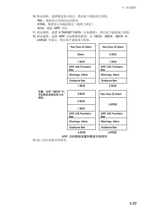
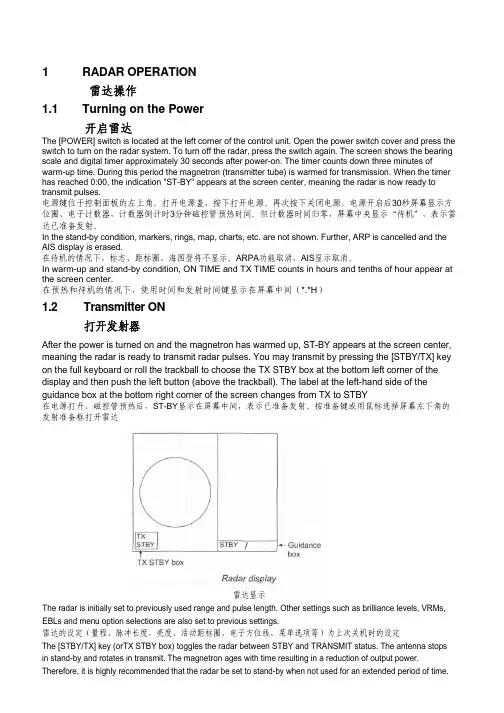
1 RADAR OPERATION雷达操作1.1 Turning on the Power开启雷达The [POWER] switch is located at the left corner of the control unit. Open the power switch cover and press the switch to turn on the radar system. To turn off the radar, press the switch again. The screen shows the bearing scale and digital timer approximately 30 seconds after power-on. The timer counts down three minutes of warm-up time. During this period the magnetron (transmitter tube) is warmed for transmission. When the timer has reached 0:00, the indication "ST-BY" appears at the screen center, meaning the radar is now ready to transmit pulses.电源键位于控制面板的左上角。
打开电源盖、按下打开电源。
再次按下关闭电源。
电源开启后30秒屏幕显示方位圈、电子计数器,计数器倒计时3分钟磁控管预热时间。
但计数器时间归零,屏幕中央显示“待机”,表示雷达已准备发射。
In the stand-by condition, markers, rings, map, charts, etc. are not shown. Further, ARP is cancelled and the AIS display is erased.在待机的情况下,标志、距标圈、海图登将不显示。

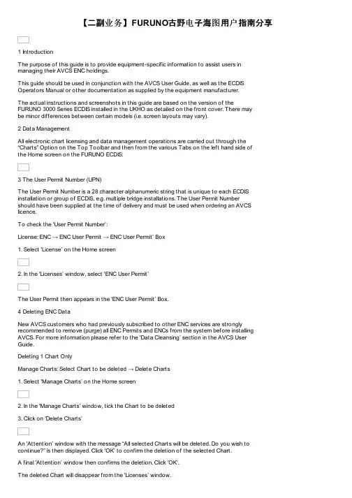
【二副业务】FURUNO古野电子海图用户指南分享1 IntroductionThe purpose of this guide is to provide equipment-specific information to assist users inmanaging their AVCS ENC holdings.This guide should be used in conjunction with the AVCS User Guide, as well as the ECDIS Operators Manual or other documentation as supplied by the equipment manufacturer.The actual instructions and screenshots in this guide are based on the version of theFURUNO 3000 Series ECDIS installed in the UKHO as detailed on the front cover. There maybe minor differences between certain models (i.e. screen layouts may vary).2 Data ManagementAll electronic chart licensing and data management operations are carried out through the “Charts” Option on the Top Toolbar and then from the various Tabs on the left hand side ofthe Home screen on the FURUNO ECDIS:3 The User Permit Number (UPN)The User Permit Number is a 28 character alphanumeric string that is unique to each ECDIS installation or group of ECDIS, e.g. multiple bridge installations. The User Permit Numbershould have been supplied at the time of delivery and must be used when ordering an AVCS licence.To check the 'User Permit Number’:License: ENC → ENC User Permit → ENC User Permit’ Box1. Select 'License’ on the Home screen2. In the 'Licenses’ window, select 'ENC User Permit’The User Permit then appears in the 'ENC User Permit’ Box.4 Deleting ENC DataNew AVCS customers who had previously subscribed to other ENC services are strongly recommended to remove (purge) all ENC Permits and ENCs from the system before installing AVCS. For more information please refer to the 'Data Cleansing’ section in the AVCS UserGuide.Deleting 1 Chart OnlyManage Charts: Select Chart to be deleted → Delete Charts1. Select 'Manage Charts’ on the Home screen2. In the 'Manage Charts’ window, tick the Chart to be deleted3. Click on 'Delete Charts’An 'Attention’ window with the message “All selected Charts will be deleted. Do you wish to continue?” is then displayed. Click 'OK’ to confirm the deletion of the selected Chart.A final 'Attention’ window then confirms the deletion. Click 'OK’.The deleted Chart will disappear from the 'Licenses’ window.Deleting ALL ChartsManage Charts:Right-click to left of Type box → Select All → Delete Charts1. Select 'Manage Charts’ on the Home screen2. In the 'Manage Charts’ window, right-click the block to the left of the 'Type’ box.3. 2 options then appear 'Select All’ and 'Deselect All’. Click on 'Select All’.4. When all Charts are selected with a Tick in front of them, click on 'Delete Charts’An 'Attention’ window with the message “All selected Charts will be deleted. Do you wish to continue?” is then displayed. Click 'OK’ to confirm the deletion of all the selected Charts.A final 'Attention’ window then confirms the deletion. Click 'OK’.The deleted Charts will disappear from the 'Manage Charts’ window.5 Deleting ENC PermitsIf the user has previously subscribed to another ENC service it is advised to remove these ENC permits from the ECDIS system before use. The user must select the cells for which permits are to be deleted. In most instances this will simply involve selecting all cells. In certain circumstances it may be required to remove permits for individual cells, in this case simply select the cells for which permits need to be deleted.Deleting 1 Permit onlyLicense: ENC → Select Permit to be deleted → Delete Licenses1. Select 'License’ on the Home screen5. In the 'Licenses’ window, select the Chart for which the Permit is to be deleted, with a Tick in front of them6. Click on 'Delete Licenses’An 'Attention’ window with the message 'Selected group will be deleted. Do you wish to continue?’ is then displayed. Click 'OK’ to confirm the deletion of all the selected Charts.A final 'Attention’ window then confirms the deletion: '1 ENC Permit removed’. Click 'OK’. The deleted Chart will disappear from the 'Licenses’ window.Deleting ALL PermitsLicense: ENC → Select All Permits → Delete Licenses1. Select 'License’ on the Home screen2. In the 'Licenses’ window, right-click the block to the left of the 'Type’ box.3. 2 options then appear 'Select All’ and 'Deselect All’. Click on 'Select All’.4. Once all the Permits to be deleted are selected with a tick in front of them, click 'Delete Licences’ on this 'Licenses’ window.An 'Attention’ window with the message “Selected group will be deleted. Do you wish to continue?” is then displayed. Click 'OK’ to confirm the deletion of all the selected Charts.A final 'Attention’ window then confirms the deletion: 'XXX ENC Permits removed’. Click 'OK’. The deleted Charts will now disappear from the 'Licenses’ window.6 The Public KeyThe Admiralty Vector Chart Service currently uses the IHO.CRT, issued by the International Hydrographic Organisation, to authenticate its AVCS ENCs. However, the Furuno 3000 ECDIS uses the IHO.PUB Public Key which is included in all AVCS Media.To view the installed Public KeyPublic Key: Select Public Key window → Display Content1. Select 'Public Key’ Menu on the Home screen2. In the 'Select Public Key’ window appearing, when a Public Key is already activated, an 'A’populates the box next to the selected Public Key3. Click on 'Display Content’ to view the already activated Public KeyTo install a new Public KeyPublic Key: Select Public Key window → Load New Key1. Select 'Public Key’ Menu on the Home screen2. In the 'Select Public Key’ window appearing, click on 'Load New Key’ to install a new Public KeyOn the next 'Open File’ window, select the location where the new Public Key to install is stored (i.e. CD, DVD, USB). Select the IHO.PUB and click 'Open’.An 'Attention’ message confirming the installation of the new Public Key will appear on the screen. Click 'OK’.3. Highlight the new Public Key and select 'Activate’ to select the required Public Key to be installed4. An 'A’ will then populate the box next to the selected Public Key.5. Click 'Close’ to finish.7 Installing ENC PermitsTo install AVCS ENC Permits:License: Licenses → ENC Tab → Install Licenses → Select File window → Permit.txt file →Open → OK1. Select 'License’ on the Home screen and in the 'Licenses’ window, select the 'ENC’ Tab2. Select 'Install Licenses’In the next 'Select File’ window, highlight the Permit.txt file from the selected source location (i.e. USB), click 'Open’ and then 'OK’If needed, the Permit List can then be exported to external Media (i.e. CD, DVD, USB) by clicking on the 'Export List’ option:8 Installing AVCS Base CDsThere are currently 9 AVCS Base CDs but this number will grow as more ENCs become available for distribution within AVCS. It is unlikely that users will need to install all of the CDs in order to load all licensed ENCs. Reference to the Schedule A can avoid the unnecessary loading of some CDs and save the user time.The process described here should be used in almost all circumstances as it will automatically select data to be loaded according to the permit file installed by the user.Note: Ensure the latest permits have been installed before attempting to install any dataAuto Load: Search File Media → OK → Install Chart Data1. After having inserted the first AVCS Base CD identified in the Schedule A into the appropriate drive (i.e. D/Q), click on 'Auto Load’ on the Home screenAn 'Attention’ window then appears warning that 'this process takes time to complete and the operation speed of the system will decline. Do you wish to continue?’. Click 'OK’.Another 'Attention’ window confirms how many 'Charts are contained in the inserted AVCS Media and how many can be installed (based on the previously installed Permit file). Do you wish to continue?’. Click 'OK’.Note: Whenever Charts are cancelled, they will automatically be removed from the system. When this happens, this will be communicated in the 'Error/Warning Guidance’ window at the end of the installation.The AVCS Media will be read and a progress Bar will display on the 'Install Chart Data’ window on the screen.When the installation is complete, a window confirming the installation will appear, click'Confirm’(this window can take some time to appear even if the Progress Bar shows a completion rate of 100%)To check the details of the data installation, click on 'Show Details’ on the 'Install Chart Data’window. Click 'Finish’ to close. This process should be repeated until all required Base CDs have been installed.Note: Make sure that all the required AVCS Base CDs have been inserted and the import operations completed before installing the latest Update CD. Updates cannot be applied unless the ENC base file is present in the system database.9 Installing AVCS Update CDThe Weekly AVCS Update CD must only be inserted into the CD Drive after having installed the latest required Base CD(s).Insert the latest AVCS Update CD into the appropriate Drive (i.e. D/Q)Note: Base CDs are re-issued about every 6 to 8 weeks. The AVCS Update disc will indicate which Base disc week must have been installed. It is important that users do not attempt to load an Update CD that is not consistent with the Base CDs.Auto Load: Search File Media → OK → Install Chart Data1. Click on 'Auto Load’ on the Home screenAn 'Attention’ window then appears warning that 'this process takes time to complete and the operation speed of the system will decline. Do you wish to continue?’. Click 'OK’.Another 'Attention’ window confirms how many 'Charts are contained in the inserted AVCS Media and how many can be updated (based on the previously installed Permit file). Do you wish to continue?’. Click 'OK’.Note: Whenever Charts are cancelled, they will automatically be removed from the system. When this happens, this will be communicated in the 'Error/Warning Guidance’ window at the end of the installation.The AVCS Media will be read and a progress Bar will display on the 'Install Chart Data’ window on the screen.When the installation is complete, a window confirming the installation will appear, click'Confirm’(this window can take some time to appear even if the Progress Bar shows a completion rate of 100%)To check the details of the data installation, click on 'Show Details’ on the 'Install Chart Data’window. Click 'Finish’ to close.10 Installing AVCS DVDWhen using the AVCS DVD Service, only one disc needs to be installed because it contains all the Base ENCs and Updates up to the date of its issue.Insert the latest AVCS DVD into the appropriate Drive (i.e. D/Q)Note: The loading process within the ECDIS will be very similar to that required for the AVCS CD Service however there are some minor differences which are detailed belowAuto Load: Search File Media → OK → Install Chart Data1. Click on 'Auto Load’ on the Home screenAn 'Attention’ window then appears warning that 'this process takes time to complete and the operation speed of the system will decline. Do you wish to continue?’. Click 'OK’. Another 'Attention’ window confirms how many 'Charts are contained in the inserted AVCS Media and how many can be installed (based on the previously installed Permit file). Do you wish to continue?’. Click 'OK’.Note: Whenever Charts are cancelled, they will automatically be removed from the system. When this happens, this will be communicated in the 'Error/Warning Guidance’ window at the end of the installation.The AVCS Media will be read and a progress Bar will display on the 'Install Chart Data’ window on the screen.When the installation is complete, a window confirming the installation will appear, click'Confirm’(this window can take some time to appear even if the Progress Bar shows a completion rate of 100%)To check the details of the data installation, click on 'Show Details’ on the 'Install Chart Data’window. Click 'Finish’ to close.11 Installing AIO PermitsThe Admiralty Information Overlay (AIO) is installed in the Furuno FMD 3000 ECDIS by installing the Cell GB800001 included in the PERMIT.TXT file and then the AIO Data.To install the AIO Permits:License: Licenses → ENC Tab → Install Licenses → Select File window → Permit.txt file →Open → OK1. Select 'License’ on the Home screen and in the 'Licenses’ window, select the 'ENC’ Tab2. Select 'Install Licenses’In the next 'Select File’ window appearing, highlight the Permit.txt file which contains the AIO Permit from the selected source location (i.e. USB), click 'Open’ and then 'OK’3. The AIO Permit will now appear in the Licenses List12 Installing AIO CDThe AIO Media can only be installed when the usual AVCS S-63 1.1 Data has been previously installed. After having previously installed the Permit for the AIO Cell GB800001, the AIO Media now needs to be installed.Insert the latest AIO CD into the appropriate drive (i.e. D/Q)Auto Load: Search File Media → OK → Install Chart Data1. Click on 'Auto Load’ on the Home screenAn 'Attention’ window then appears warning that 'this process takes time to complete and the operation speed of the system will decline. Do you wish to continue?’. Click 'OK’.Another 'Attention’ window confirms how many 'Charts are contained in the inserted AVCS Media and how many can be installed (based on the previously installed Permit file). Do you wish to continue?’. Click 'OK’.The AIO CD will be read and a progress Bar will display on the 'Install Chart Data’ window on the screen.When the installation is complete, a window confirming the installation will appear, click'Confirm’(this window can take some time to appear even if the Progress Bar shows a completion rate of 100%)To check the details of the data installation, click on 'Show Details’ on the 'Install Chart Data’window. Click 'Finish’ to close.2. Once the AIO Permits and Media have been installed, the AIO is enabled3. If needed, the system will give the user the option of then disabling the AIO from the'Licenses’ window:13 Systems ChecksThe user has the option to review the status of all installed ENCs on the Furuno FMD 3000 ECDIS by consulting various Reports.1. Select 'Record’ on the Home screen2. Select 'Chart Log’3. Select 'ENC’A Report containing all the installed Cells then appears on the screen. This Report contains information about all the Update status of the Cells currently installed on the system. Select 'Close’ to close the Report.The Furuno FMD 3000 ECDIS displays the Cell status of the Cells installed within a colour coding system on the Geographical Display:Green: The Permit is valid and the ENC is available for use in SENC format. If the source of the ENC is a RENC, then the ENC is also up-to-date. If the source of the S-57 vector chart is something other than a RENC then all loaded updates are included into the SENC.Orange: You have a valid Permit and the ENC is available for use in SENC format but it is either not up-to-date or has been cancelled. This could be for several reasons, either the SENC is from a previous edition, the latest SENC update was missed or the ENC has been cancelled.Red: If an ENC is installed in the SENC but does not have a corresponding permit installed then the ENC is no longer available for display in the viewer.Blue: The conversion of the Cells from RENC to SENC as somehow failed during the conversion process. This can be due to a software upgrade or an issue with the data itself preventing the Furuno from successfully converting to SENC. For example, one Cell was up-to-date before a software upgrade and was not updated when the software was upgraded. Then the Cell would show as blue until the conversion process is completed. Contrary to the Magenta colour which means that the RENC to SENC conversion was not even started. Magenta: You have a permit to use the ENC, but the installed ENC is not available in SENC format and thus you cannot use the ENC currently.It is also possible to check the updating status of all Cells installed within the Cell Status mode:1. Select 'Cell Status’ on the Home screen2. The 'Cell Status’ window then appears displaying the Updating status of all Cells installed: If screenshots need to be taken (i.e. report specific issues), this is carried out in the Furuno FMD 3000 by clicking on 'Capture Screenshot’ on the Home screen.When the required screenshot is taken, it will be automatically saved on the system within the 'Settings’ Tab on the top MenuIn the next 'Settings’ window, find the screenshot previously taken (usually at the bottom of the drop down list), highlight it with a tick on its left hand side and then click on 'Export’. This will open a new window where you can then save this screenshot on the preferred source location (i.e. USB).14 TroubleshootingMany of the difficulties that could be experienced when using the Admiralty Vector Chart Service with this system can be avoided by carefully following the instructions in this guide. However, issues that are known to have caused confusion in the past are detailed in the Frequently Asked Questions (FAQ) section which can be found at:If you encounter problems that are not solved by referring to the FAQs, you may wish to seek Technical Support. Please see the section below for contact details.Who should you contact?You will receive the most effective support if you address your initial query to either yourECDIS Manufacturer or ADMIRALTY Chart Agent, but in certain circumstances you may need to contact the UKHO Customer Services.When reporting a chart related problem it is useful if you can provide the following details:> Licence number> Vessel name> ECDIS/Software Manufacturer> Details of error message – Including 'SSE’ error code> Screen shot(s) of error> Details of Base Discs used (date)> Details of Update CD used (date)> Details of Permits used (date)> Details of Cell number(s) errors apply to> Have there been any configuration changes to system(s)> Details of User Permit(s) and PIN Number(s)Emergency Chart Permit GenerationIn certain circumstances it may be necessary for a vessel to get access to an AVCS chart at very short notice, for instance if a route needs to be diverted due to a medical or safety emergency.In these emergency circumstances only, individual AVCS ENC Permits can be obtained from the UKHO 24 hours a day, 365days a year.To obtain the AVCS emergency permit, please quote:> Vessel Name> ECDIS User Permit Number> Required ENCsThe permits can be sent directly to the vessel by email wherever possible, by fax, or simply by reading the characters out over the telephone or radio.Please contact UKHO Customer Services using the contact details below:。

Electronic Chart Display and Information System (ECDIS)OPERATOR'S MANUALwww.furuno.co.jpMODEL FEA-2107 FEA-2107-BB FEA-2107-D FEA-2807FEA-2807-DInstructions for use with Autopilots: FAP-2000PT -500A(CAT B, CAT C) PR-6000The paper used in this manualis elemental chlorine free.9-52 Ashihara-cho,Nishinomiya, 662-8580, JAPANForewordThe purpose of this manual is to provide the instructions for how to use the Autopilots FAP-2000,PT-500A(CAT B and CAT C)1 and PR-60002 with the FURUNO FEA-2107-D, FEA-2107-BB-D, FEA-2807-D Electronic Chart Display and Information System (ECDIS). For ECDIS operating information, see its Operator's Manual.1 PT-500A(CAT B and CAT C) are products of YOKOGAWA ELECTRIC CORPORATION.2 PR-6000 is a product of TOKYO KEIKI INCImportant Notices• The operator of this equipment must read and follow the descriptions in this manual. Wrong operation can cancel the warranty or cause injury.• Do not copy any part of this manual without written permission from FURUNO.• If this manual is lost or worn, contact your dealer about replacement.• The contents of this manual and equipment specifications can change without notice.• The example screens (or illustrations) shown in this manual can be different from the screens you see on your display. The screens you see depend on your system configuration and equipment settings.• Save this manual for future reference.• Any modification of the equipment (including software) by persons not authorized by FURUNO will cancel the warranty.• All brand and product names are trademarks, registered trademarks or service marks of their respective holders.iSafety Instructionsiiabout replacement.ype: 86-003-1011-0Safety InstructionsTable of ContentsSYSTEM CONFIGURATION (vii)1.FURUNO Autopilot FAP-2000..............................................................................................1-11.1Introduction.............................................................................................................................1-11.2Control Panel...........................................................................................................................1-11.3Steering Modes........................................................................................................................1-31.3.1Hand steering modes..................................................................................................1-31.3.2Autopilot steering modes............................................................................................1-31.3.3Route steering modes..................................................................................................1-51.4Additional Information About Steering Modes....................................................................1-161.5Important Information About Steering Mode Changes......................................................1-181.6Autopilot Display in Sidebar.................................................................................................1-191.7Expected Steering Performance Under Various Conditions...............................................1-201.7.1Expected steering performance for going ahead.....................................................1-201.7.2Expected steering performance for turns................................................................1-231.8Expected Steering Performance Under Critical Failure.....................................................1-251.8.1Lost heading from autopilot (ECDIS may also have lost heading)........................1-251.8.2Lost heading from ECDIS (autopilot still has heading).........................................1-251.8.3Lost speed..................................................................................................................1-261.8.4Low speed..................................................................................................................1-261.8.5Lost SOG/COG reference..........................................................................................1-271.8.6Total lost position......................................................................................................1-281.8.7Lost differential position..........................................................................................1-291.8.8Lost differential position and position discrepancy................................................1-301.8.9Lost communication between ECDIS and autopilot...............................................1-301.8.10Lost communication between autopilot and ECDIS...............................................1-301.9Other Operations...................................................................................................................1-311.10Alerts......................................................................................................................................1-311.10.1Alerts generated by autopilot...................................................................................1-311.10.2Alerts generated by ECDIS......................................................................................1-321.10.3Error alerts generated by autopilot.........................................................................1-371.11How to Use the Curved EBL.................................................................................................1-381.11.1What is the curved EBL?..........................................................................................1-381.11.2Structure of the curved EBL.....................................................................................1-391.11.3How to design a new turn while the ship is turning...............................................1-391.12How to Use the Predictor......................................................................................................1-402.YOKOGAWA Autopilot PT-500A (category B).......................................................................2-12.1Introduction.............................................................................................................................2-12.2Steering Control Unit..............................................................................................................2-12.3Steering Modes........................................................................................................................2-22.3.1Hand steering mode (Mode selector: HAND)............................................................2-22.3.2Autopilot steering mode (Mode selector: AUTO).......................................................2-22.3.3Route steering mode (Mode selector: NAVI)..............................................................2-22.4Other Operations...................................................................................................................2-102.5Alerts Generated by ECDIS..................................................................................................2-102.5.1Operational alerts.....................................................................................................2-102.5.2Error alerts................................................................................................................2-132.6Autopilot Display in Sidebar.................................................................................................2-142.7Expected Steering Performance Under Various Conditions...............................................2-152.7.1Expected steering performance for going ahead.....................................................2-152.7.2Expected steering performance for turns................................................................2-162.8Expected Steering Performance Under Critical Failure.....................................................2-172.8.1Lost heading from autopilot (ECDIS may also have lost heading)........................2-172.8.2Lost heading from ECDIS (autopilot still has heading).........................................2-17iiiTable of Contentsiv2.8.3Lost speed..................................................................................................................2-182.8.4Low speed..................................................................................................................2-192.8.5Total lost position......................................................................................................2-202.8.6Lost differential position and position discrepancy................................................2-212.8.7Lost communication between ECDIS and autopilot...............................................2-222.8.8Lost communication between autopilot and ECDIS...............................................2-22 2.9How to Use the Curved EBL.................................................................................................2-23 2.10How to Use the Predictor......................................................................................................2-243.YOKOGAWA Autopilot PT-500A (category C).......................................................................3-13.1Introduction..............................................................................................................................3-13.2Steering Control Unit..............................................................................................................3-13.3Steering Modes.........................................................................................................................3-23.3.1Hand steering mode (Mode selector: HAND)............................................................3-23.3.2Autopilot steering mode (Mode selector: AUTO).......................................................3-23.3.3Route steering mode (Mode selector: NAVI)..............................................................3-23.4Other Operations...................................................................................................................3-113.5Alerts Generated by ECDIS..................................................................................................3-123.5.1Operational alerts.....................................................................................................3-123.5.2Error alerts................................................................................................................3-123.6Autopilot Display in Sidebar.................................................................................................3-133.7Expected Steering Performance Under Various Conditions...............................................3-143.7.1Expected steering performance for going ahead.....................................................3-143.7.2Expected steering performance for turns................................................................3-153.8Expected Steering Performance Under Critical Failure.....................................................3-163.8.1Lost heading from autopilot (ECDIS may also have lost heading)........................3-163.8.2Lost heading from ECDIS (autopilot still has heading).........................................3-163.8.3Lost speed..................................................................................................................3-173.8.4Low speed..................................................................................................................3-173.8.5Lost SOG/COG reference in GoAW mode................................................................3-183.8.6Total lost position......................................................................................................3-183.8.7Lost differential position in GoAW mode.................................................................3-193.8.8Lost differential position and position discrepancy................................................3-203.8.9Lost communication between ECDIS and autopilot...............................................3-213.8.10Lost communication between autopilot and ECDIS...............................................3-213.9How to Use the Curved EBL.................................................................................................3-214.TOKYO KEIKI Autopilot PR-6000.......................................................................................4-14.1Introduction..............................................................................................................................4-14.2Steering Control Unit..............................................................................................................4-14.3Steering Modes.........................................................................................................................4-24.3.1Hand steering mode (Mode selector: HAND)............................................................4-24.3.2Autopilot steering mode (Mode selector: AUTO).......................................................4-34.3.3Non-Follow-Up steering mode (Mode selector: NFU)...............................................4-34.3.4Remote hand steering mode (Mode selector: RC)......................................................4-44.3.5Steering override units...............................................................................................4-54.3.6Route steering mode, RC/Nav (Mode: RC).................................................................4-64.4HCS Unit Controls.................................................................................................................4-174.5Alerts Generated by ECDIS..................................................................................................4-184.5.1Operational alerts.....................................................................................................4-184.5.2Error alerts................................................................................................................4-184.6Autopilot Display in Sidebar.................................................................................................4-194.7Expected Steering Performance Under Various Conditions...............................................4-214.7.1Expected steering performance for going ahead.....................................................4-214.7.2Expected steering performance for turns................................................................4-224.8Expected Steering Performance Under Critical Failure.....................................................4-244.8.1Lost heading from autopilot (ECDIS may also have lost heading).......................4-244.8.2Lost heading from ECDIS (autopilot still has heading).........................................4-244.8.3Lost speed..................................................................................................................4-254.8.4Low speed..................................................................................................................4-25Table of Contentsv4.8.5 Lost SOG/COG reference in GoAW steering mode .................................................4-26 4.8.6 Total lost position......................................................................................................4-26 4.8.7 Lost differential position in GoAW steering mode..................................................4-27 4.8.8 Lost differential position and position discrepancy................................................4-27 4.8.9 Lost communication between ECDIS and autopilot...............................................4-28 4.8.10 Lost communication between autopilot and ECDIS...............................................4-28 4.9 How to Use the Curved EBL.................................................................................................4-29 4.10 How to Use the Predictor......................................................................................................4-30Index..........................................................................................................................................IN-1Table of ContentsThis page intentionally left blank. viSYSTEM CONFIGURATIONSingle workstationviiSystem Configurationviii Multi workstation: M A N D A T O R Y: A L T E R N A T I V E : O P T I O N A L : O P T I O N A L , B U T N O T U S E D B Y T C S : E X T E R N A L S E N S O R o r E Q U I P M E N TN o t e 1 A l t e r n a t i v e s a r e , G y r o c o m p a s s b y I E C 61162 o r S t e p p e rN o t e 2 A l t e r n a t i v e s a r e , L o g b y I E C 61162 o r 200p /n m1. FURUNO AutopilotFAP-20001.1 IntroductionThis chapter describes the steering functions available with the FURUNO Autopilot FAP-2000.1.2 ControlPanelThis section describes the FAP-2000's control panel.FURUNO1-6: Steering mode selection• PROGRAM TRACK:Program Track-controlled heading change using set radius. Also for steering with selected TT models.• GOTO TRACK:Track-controlled route steering• GOTO WPT: Course-controlled route steering• HEADING CONTROL: Immediate heading-controlled course change using set rudder angle limit• RADIUS CONTROL: Immediate radius-controlled course change using set radius• PROGRAM HEADING CHANGE: Program heading-controlled course change using set radius1-11. FURUNO Autopilot FAP-20007: Loading condition indicator: Loading conditions, Light, Medium or Loaded8: Performance indicator:Performance status, Economy, Medium or Precise9: Status indicator: Shows selected mode and state of readiness:• FAP-2000 in operation: READY• FAP-2000 control mode: HEADING/TRACK• FAP-2000 route steering: ROUTE• FAP-2000 track-controlled turn: TURN10: Alert indicator and buzzer cancel• ALERT lamp for other FAP-2000-related alerts and errors.• RESET button for acknowledging other FAP-2000-related alerts and errors.11: Special function keypads• Manually input speed.• Adjust panel dimmer.• Set manual speed value, auto speed, rudder limit function, performance and conditions.12: Tiller• Set course and radius.• PORT and STBD lamps show when the tiller can be used to set course.• INCREASE. and DECREASE. lamps show when the tiller can be used to set a radius or a rudder angle limit. 13: Gyro reading and a bar graph showing rate of turn14: Set Heading display includes:• Off course alert• Turn side• Rudder-on limit indication15: Rudder displays:• Radius set-point in the Radius Control mode• Rudder limit in the Heading Control mode• AUTO LIMIT lamp lights to indicate selection of automatic rudder limit function.16: Speed displays:• ROT in the Radius Control mode• Speed in the Heading Control mode• Speed warning indicator (LOG FAILURE or LOW)1-21. FURUNO Autopilot FAP-20001-31.3 Steering ModesThe FAP-2000 receives position, heading and speed data, compares them with the track section to be steered, and applies that information to calculate and command the necessary rudder angle.1.3.1 Hand steering modesThe following hand steering modes are available without the autopilot:• Steering wheel • Wing steering control • Override tillerWhile in a hand steering mode, the ECDIS indicates the rudder angle and the hand steering mode.1.3.2 Autopilot steering modesThe autopilot steering modes are selected from the autopilot control panel.Heading Control modeThe Heading Control steering mode can be used always because it does not require position data.• Mode selection: HEADING CONTROL• The HEADING CONTROL and HEADING lamps are lit. • Immediate course change when the tiller is used to set the heading. • Course change is defined as heading controlled by the set rudder angle limit. Radius Control modeThe Radius Control steering mode can be used always because it does not require position data.• Mode selection: RADIUS CONTROL• RADIUS CONTROL and HEADING lamps are lit. • Course change is radius controlled with the set radius.• If wind, current, etc. affect the ship, the ship will drift (inside or outside) from the planned turn. This is displayedon the radar screen.Program Heading Change modeThe Program Heading Change steering mode can be used always because it does not require position data.• Mode selection: PROGRAM HEADING CHANGE• PROGRAM HEADING CHANGE and HEADING lamps are lit.• The tiller is first used to set a new heading and radius, which are also displayed on the radar screen.• "START HEADING CHANGE" flashes if the newly set heading is different from the currently used heading. • Start course change by pushing the START HEADING CHANGE button. • After activation, control is returned to RADIUS CONTROL.• If wind, current, etc. affect the ship, the ship will drift away (inside or outside) from planned turn. This isdisplayed on the radar screen.1. FURUNO Autopilot FAP-20001-4Program Track modeThe Program Track steering mode requires the Kalman filter and a high-precision sensor such as DGPS:• Mode selection: PROGRAM TRACK• PROGRAM TRACK, TRACK and TURN lamps are lit.• The tiller is first used to set a new heading and radius, which are also displayed on the radar screen. • "START HEADING CHANGE" flashes if newly set heading is different from currently used set heading. • Start course change by pushing the START HEADING CHANGE button. • After activation, the mode becomes PROGRAM TRACK. • Course change is track controlled with the set radius.• If wind, current, etc. affect the ship, the system tries to prevent the ship from drifting away (inside or outside)from the planned designed turn. This is displayed on the radar screen. Alerts in the Program Track steering modeThe following alerts may appear in the Program Track steering mode.Alert "488 Track Control Stopped ": Internal failure - program track mode is cancelled.Alert "493 PrgTrack : Needs Filter ON ": The Kalman filter is not used with the program track mode. This alert is repeated every four minutes for the next 10 minutes. If the condition continues, the alert "496 ProgTrack : Stop - Sensor Fail " is generated and the steering mode is automatically changed to "Radius Control".Alert "494 PrgTrack : Needs Log sens.": The Kalman filter is used with the program track mode but withoutincluding an independent speed source (separate log sensor or two position sensors). This alert is repeated every four minutes for the next 10 minutes. If the condition continues, the alert "496 ProgTrack : Stop - Sensor Fail " is generated and the steering mode is automatically changed to "Radius Control".Alert "495 PrgTrack : Needs diff Pos.": The Kalman filter is used with the program track mode but without a high-precision sensor (for example, DGPS). This alert is repeated every four minutes for the next 10 minutes. If the condition continues, the alert "496 ProgTrack : Stop - Sensor Fail " is generated and the steering mode is automatically changed to "Radius Control".Alert "496 PrgTrack : Stop - Sensor Fail ": No gyro data or if conditions of alert 493, 494, 495 or 503 have been valid for the last 10 minutes.Alert "498 Use manual rudder control ": Generated every two minutes to alert the operator to control the rudder manually, when the FAP-2000 has lost the gyro data and thus cannot control the rudder.Alert "503 PrgTrack : Need higher Spd ": The Kalman filter is used with the program track mode but the speed is below the limit set for the track steering in the installation parameters. The alert is repeated every four minutes for the next 10 minutes. If the condition continues, the alert "496 ProgTrack : Stop - Sensor Fail " is generated and the steering mode is automatically changed to "Radius Control".Alert "504 PrgTrack : Use Radius ctrl.": Informs the operator to change the steering mode to "Radius Control". This alert is generated if there are not sufficient conditions to continue the program track (i.e. alert 493, 494, 495 or 503 has been valid two minutes). This alert is repeated every four minutes.Alert "509 PrgTrack : Need SOG/COG ref ": Appears when there is no Speed Over Ground (SOG) and Course Over Ground (COG) available from the position sensor(s) or bottom track from a dual-axis log. This alert isrepeated every four minutes for the next 10 minutes. If the condition continues, the alert "496 ProgTrack : Stop - Sensor Fail " is generated and the steering mode is automatically changed to "Radius Control".1. FURUNO Autopilot FAP-20001-5Summary of autopilot steering modesHEADING CONTROLRADIUS CONTROLPROGRAM HEADING CHANGEPROGRAM TRACKSet heading Set radius Radius control Design before execution Full curved EBL on radar screen Wind, current, etc. compensation Yes No No No No No Yes Yes Yes No Yes No Yes Yes Yes Yes Yes No Yes Yes Yes Yes Yes Yes Needs gyro Needs logNeeds high-precision position Needs direct SOG/COG sensorYes No No NoYes YesNo NoYes Yes No NoYes Yes Yes Yes1.3.3 Route steering modesIn route steering, you can use either the Goto WPT mode or the Goto Track mode. Route steering is available with a predefined monitored route and when your ship is located inside a channel of a monitored route.See the figure below for the differences between Goto WPT and Goto Track. As shown, the ship will always make way toward the waypoint in Goto WPT, and return to set course in Goto Track.WPTWPTWPTWPTWPT"Goto WPT"WPT“Goto Track"Note : If the off track error is more than 100 meters in the Goto Track mode, the system cannot increase the approach angle towards the center line of the route.1. FURUNO Autopilot FAP-20001-6Goto WPT mode • Mode selection: Goto WPT• Goto WPT and ROUTE lamps are lit.• The tiller can be used to set radius, but not course, which is set automatically. • Steering is course controlled with set radius.• If wind, current, etc. affect the ship between waypoints, the system tries to prevent the ship from drifting fromthe planned route. The system has three means to prevent drifting from the planned route, and they are most effective when used together. If cross-track error is used alone, your ship stabilizes typically in a constant off-track position. The means are:• Measured cross-track error from the centerline, which is always active. • Drift compensation available from route parameters • Gyro error compensation available from route parameters• If wind, current, etc. affect the ship during turns, the ship will drift (inside or outside) from the planned turn,which is displayed on the radar screen. This kind of turn is called an "assisted turn".• Can be used when the ship has an accurate position source available.• Normally, the Goto WPT mode uses the dynamic location of a waypoint. However, if alert 413 is active, a non-dynamic waypoint is used. The figure below shows how the location of a dynamic WPT is defined in the Goto WPT mode.used by "Goto Track"Goto Track mode • Mode selection Goto TRACK• Available when the ship has a high-precision position source available. • The GOTO TRACK button and ROUTE and TRACK lamps are lit.• The tiller can be used to set radius, but not heading, which is set automatically. • Steering is track-controlled with set radius.• If wind, current, etc. affect the ship between waypoints, the system tries to prevent the ship from drifting fromthe planned route. The system has three means to prevent drifting from the planned route, and they are most effective when used together. If cross-track error is used alone, your ship stabilizes typically in a constant off-track position. The means are:• Measured cross-track error from the centerline, which is always active. • Drift compensation is available from the route parameters. • Gyro error compensation is available from the route parameters. • The Goto Track mode uses non-dynamic waypoint.。

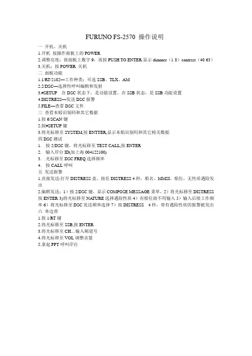
FURUNO FS-2570 操作说明
一开机、关机
1.开机按操作面板上的POWER
2.调整亮度:按面板上数字9,再按PUSH TO ENTER.显示dimmer(1-8)contrast(40-63)
3.关机:按POWER 关机
二面板功能
1.1/RT/2182—工作种类:可选SSB、TLX、AM
2.2/DSC—选择性呼叫编辑和发射
3.#SETUP---在DSC状态下,是功能设置。
在SSB状态,是SSB功能设置
4.DISTRESS—发送DSC报警
5.FILE—查看DSC文件
三查看本船识别码和其它数据
1.按6/SCAN键
2.按#SETUP键
3.将光标移至SYSTEM,按ENTTER,显示本船识别码和其它相关数据
四DSC测试
1.按2/DSC键,将光标移至TEST CALL,按ENTER
2.输入岸台ID(如上海004122100)
3.光标移至DSC FREQ选择频率
4.按CALL呼叫
五发送报警
1.直接发送:打开DISTRESS盖,按住DISTRESS 4秒,船名、MMSI、船位,无性质遇险发出
2.编辑发送:1)按2/DSC键,显示COMPOSE MESSAGE菜单,2)将光标移至DISTRESS 按ENTER 3)将光标移至NATURE选择遇险性质4)有船位就不用输入5)输入后续工作频率6)将光标移至DSC发送频率选择7)按DISTRESS 4秒,带有遇险性质的报警被发出六单边带
1.按1/RT键
2.将光标移至SSB,按ENTER
3.将光标移至CH…输入频道号
4.将光标移至VOL调整音量
5.拿起PPT呼叫岸台。

FURUNO 中/高频组合电台及终端设备操作指南第一节组合电台控制单元操作一、简介FS-1570是SSB无线电话,DSC中高频数值选呼和NBDP窄带直接印字电报的组合终端,整机组成包括中高频天线一付、天线调谐、收发机、SSB和DSC终端控制单元、话柄、NBDP终端显示器、键盘、打印机等。
二、控制单元面板及键钮功能介绍见图4-1-1图4-1-11.[POWER ]键:电源开关。
2.[DISTRESS]键: 按住此键3秒钟以上发射遇险报警。
3.[CALL]: 发射键。
4.[ENTER knob]键:(1)当选择无线电话通信方式时,旋转该旋钮,选择无线电话信道、灵敏度、音量等,按下为确认选项;(2)当选择DSC工作方式时,旋转该旋钮,选择菜单项,按下为确认选项。
5.[CANCEL]键:(1)取消错误数据;(2)回到上一级菜单;(3)取消报警声;(4)取消发射打印;(5)删除电文。
6.[1/RT/2182]键:(1)选择数字1;(2)选择无线电话方式;(3)按住该键2秒以上,转到2182.0kHz/J3E方式。
7. [2/DSC/ABC]键:(1) 选择数字2;(2)选择DSC方式;(3)选择字母A、B或者C。
8. [3/TEST]键:(1)选择数字3;(2)进行测试。
9. [4/Intcom] 键:(1) 选择数字4;(2)控制单元和遥控单元的内部通信。
10.[5/Ack/SQ] 键:(1)选择数字5;(2)DSC方式工作时,自动应答和人工应答转换;(3)无线电话工作(RT)时,静噪的开/关。
11.[6/SCAN] 键:(1)选择数字6;(2)显示标准DSC显示界面,DSC常规植守频率扫描的开始与停止。
12. [7/]键:(1)选择数字7;(2)外接蜂鸣器的开/关。
13.[8//PRINT] 键:(1)选择数字8;(2)打印通信电文;当时的屏显内容(除DSC标准屏显和无线电话屏显)和测试结果。
14. [9/]键:(1)选择数字9;(2)调整面板亮度和LCD对比度。
古野FURUNO FM-8500 VHF/DSC的使用介绍前述1:取消错误的遇险报警1.立即关掉发射机。
2.打开设备,放在16频道。
3.把你的船名、呼号、DSC号码向所有船作一个广播,同时取消错误的遇险报警。
例子:A L L S T A T I O N S,A L L S T A T I O N S,A L L S T A T I O N S所有船,所有船,所有船THIS IS NAME,CALL SIGN,我是XX船,呼号是,DSC NUMBER,POSITION. DSC号码是,船位,CANCEL MY DISTRESS ALERT OF 取消我于日期、UTC时间DATE,TIME UTC. 发的遇险报警=MASTER, NAME, CALL SIGN, XX轮船长DSC NUMBER, DATE, TIME UTC. 重复XX船,呼号,DSC号码,日期、时间。
前述2:系统结构图CH70天线图-1 FM-8500系统结构图FM-8500是由一个主收发单元和两根天线构成。
收发单元包括VHF发射部分、接收部分和70频道DSC值守机。
该机的性能和操作全部是由前面板控制。
一根天线用于VHF发射和接收,另一根天线用于DSC值守。
第一节VHF 无线电话各旋钮功能1.1 控制,指示控制 CHANNEL/ 用于选择一个频道。
MODE 按下这个旋钮,用于在INTL 、USA 、WX 和PRIV 四种模式之间转换。
SQUELCH/ 用于静噪比。
当所选的频道没有人讲话时,自动降低噪音,使接收机哑声。
DW/SCAN 按一下这个旋钮,可以改变操作模式:双值守,扫描和关掉这两项功能。
VOLUME/ 开机、关机和调整喇叭音量。
LOUDSPEAKER 按一下这个旋钮,用于打开和关掉喇叭。
HI/LOW key 高功率/低功率 CH16 key 16频道指示1.2 电话操作开机关机 顺时钟旋转VOLUME 直到听见一声响,就可以开机;逆时钟旋转VOLUME 直到听见一声响,就可以关机。
Models GP-7000/7000FRThe future today with FURUNO's electronics technology.FURUNO ELECTRIC CO., LTD.9-52 Ashihara-cho, Nishinomiya City, Japan Phone: +81 (0)798 65-2111Fax: +81 (0)798 65-4200, 66-4622 URL: www.furuno.co.jpTRADE MARK REGISTERED MARCA REGISTRADACatalogue No. N-860High brightness 7" wide TFTavailable with high performance Fish FinderCOLOR LCD GPS/WAAS PLOTTER●High-performance GPS/WAAS receiver●Sunlight viewable 7" TFT bright colorLCD (wide 16:9 aspect ratio)●Compatible with C-Map NT +chart cards ●Dual SD card slots for memory and chartcards (Conventional SD cards can be used for waypoint/route backup)●Enhanced chart redraw speed●Display modes: Course Plot, Nav Data,Steering, Highway●User-friendly interface and operationwith rotary encoder and soft keys ●50/200 kHz, 600 Watts or 1,000 Wattsdual-frequency fish finder (GP-7000F)Wide Area A ugmentation SystemGP-7000:GPS/WAAS PlotterGP-7000F:GPS/WAAS Plotter with Fish FinderFull-featured GPS / WAAS plotter with exceptional redraw speed anda bright LCD displaySunlight ViewableFor optimum data presentation,the GP-7000 and GP-7000Futilize a display that can beviewed in direct sunlight. It alsoprovides excellent contrast anda wide viewing angle. Specialanti-reflective filters enhancethe screen to reduce glares onthe TFT LCD.for a variety of vessels with video plotting and echo sounding capabilities*. With the GP-7000 series, you can see the highly accurate position of your boat on the chart.(*GP-7000F only)The GP-7000 series has four display modes: Course Plot, Nav Data, Steering, and Highway modes. The course plot mode is useful for obtaining general information about surrounding sea areas. The Nav data mode clearly shows importantnavigational information with large text, which is easy to see even from a distance. The steering mode and highway mode assist the operator in following a predetermined route.The GP-7000 series uses C-Map NT +charts. These charts provide navigational information including water depth,contours, coastlines, lighthouses, buoys, etc. The use of the SD cards facilitates the management of the expanded chart data.Dual+A-scopeSteering degrees and the ship's intended course is kept at the screen top like a head-up display.In True Motion modes, coastlines remain stationary on the screen while your vessel moves according to its actual speed and course. In the Relative Motion mode, your vessel is kept at the screen center and coastlines move relative to your vessel.CombinationNav DataHighway Guardian Technology™With the use of C-Map 's exclusive Guardian Technology™,you continuously scan the electronic chart data in front of the boat to detect rocks, shoals, obstructions and land areas that could pose a threat if the vessel were to continue along its currentcourse. The area searched is user-definable and is identified by a triangle on the screen. Triggering timely and clear alarms,Guardian Technology provides a new level of safety only previously available on commercial shipping systems.GPS RECEIVER CHARACTERISTICS1.Receiver Type Twelve discrete channels, C/A code,all-in-view, Integral WAAS receiver processor2.Receive Frequency L1 (1575.42 MHz)3.Accuracy GPS: 10 m (95%)WAAS: 3 m (95%)4.Time to First Fix12 s (warm start)5.Tracking velocity999 kt6.Geodetic System WGS-84PLOTTER CHARACTERISTICS1.Display7" color LCD, 480 x 234 pixels(wide 16:9 aspect ratio)2Latitude Limits Between 80°N and 80°S3.Plot Interval1, 5, 10, 30 s, 1, 5, 10, 30 m, 1 h0.01, 0.05, 0.5, 1.0, 2.0, 5.0, 10.0 nm4.Display Modes Course Plot, Nav Data, Steering Display,Highway, Combination with Echo Sounder** GP-7000F only5.Presentation Modes TM/RM North-up, Course-up,Auto Course-up6.Memory Capacity Up to 12,000 points for ship's track points,(Internal memory)2,000 waypoints and 200 planned routes(Max. 35 waypoints/route)7.Voyage Planning Waypoint navigation or route navigation8.Alarms Arrival/anchor watch, XTE, proximity alert,ship speed, depth*, water temperature*, fish**GP-7000F —Temperature sensor required forwater temp alarm.9.Interface(NMEA 0183 ver. 1.5/2.0/3.0)Outputs:AAM, APB, BOD, BWR, DBT*, DPT*, GGA, GLL, GTD, HDG, MTW*, MWV, RTE, RMA, RMB, RMC, TLL, VHW, VTG, WPL, XTE, ZDAInputs:VHW, HDT, HDG, TLL, DSC, DPT, MTW, MWV *GP-7000F10.Electronic Chart C-MAP NT chart/NT+chart11. Language English, Italian, French, German, Spanish,Norwegian, Swedish, PortugueseECHO SOUNDER (GP-7000F)1.Display Modes Normal (single- or dual-frequency), Bottom-lock,Bottom Zoom, Marker Zoom, A-scope,Combination with Plotter2.Frequency50 and 200 kHz3.Output Power600 W/1 kW (specify when ordering)4.Basic Ranges8 basic ranges customized to max 1200 m(4000 ft, 650 fa)ENVIRONMENTAL CONDITIONS (IEC 60945 test method)1.TemperatureDisplay Unit:-15°C to +55°CAntenna Unit:-25°C to +70°C2.Water ResistanceDisplay Unit:IPX5 (IEC 60529), CFR46 (USCG)Antenna Unit:IPX6 (IEC 60529), CFR46 (USCG)POWER SUPPLY12 - 24 VDC, 1.5 - 0.8 AEQUIPMENT LISTStandard1.Display Unit GP-7000/7000F 1 unit2.Antenna Unit GPA-017with 10 m cable 1 unit3.Installation Materials and Standard Spare Parts 1 set Option1.NMEA Cable with 6-6p connectors (5 m: MJ-A6SPF0012-050,10 m: MJ-A6SPF0012-100), with 6p connector (5 m: MJ-A6SPF0003-050),with 7p connector (5 m: MJ-A7SPF0007-050)2.External Cable for Antenna Unit, 30/50 m3.Antenna Mounting Base13-QA330 (Pipe mount), 13-QA310 (Offset bracket), 13-RC5160 (Handrail mount)4.Speed/Temperature Sensor ST-02MSB/ST-02PSB(GP-7000F)5.Connector Cable for Speed/Temperature Sensor6.Cable between Distribution Box and Display Unit 02S4089-07.Distribution Box MB-10008.Inner Hull Kit 22S0191-1Transducers(Specify when ordering GP-7000F)600 W520-5PSD (Plastic thru-hull), 520-5MSD (Bronze thru-hull),525-5PWD (Plastic transom)1 kW50B-6, 50B-6G, 200B-5, 200B-5S, 50/200-1T(Optional matching box required) Triducers®(Specify when ordering GP-7000F)525ST-PWD(Plastic, Transom), 525ST-MSD (Bronze, Thru-hull)。
FURUNO FR-2125 雷达操作说明第一部分雷达操作一开机电源开关[POWER]位于控制面版的左上角,按此键可开/关机。
开机后,在约15秒内,荧光屏显示方位圈及数字计时器。
计时器进行3分钟的倒计时,以便对磁控管进行预热。
当计时器到达0:00时,显示荧光屏上显示STBY,表示已处于备妥状态。
在预热及预备状态下,荧光屏显示BRG SIG MISSING (方位信号丢失),还是正常现象,因为天线不转,没有方位(水平)信号产生。
荧光屏底部显示ON TIME 及TX TIME 表示雷达的开机时间及发射时间。
二发射当荧光屏上显示备妥状态时,按控制面板上的[STBY/TX]。
雷达开机时,初始设定为上次使用过的量程及脉冲宽度。
其他参数如屏幕亮度,活动距标圈,电子方位线和菜单中的任选项也设置为上次使用时的设置。
发射开关可使雷达处于预备或发射状态,在发射状态下,天线转动;预备状态下,天线不转。
快速启动:假设雷达刚刚使用过,磁控管仍热,则不需要3分钟预热时间就可使雷达在发射状态工作。
如因操作失误等类似原因关掉了雷达,而又想立即使用,则可以在关机10秒内开机,以快速启动。
注意:1 如在发射状态下,雷达天线不转,请检查控制面板左下角的天线开关是否放在关(OFF)的位置。
2 磁控管老化可导致输出功率下降,为延长其寿命,建议在一段时间内不使用雷达时,将雷达放置在预备状态。
三控制面板[BRILLIANCE] 调整整个荧光屏的亮度[A/C RAIN] 雨雪干扰抑制[A/C SEA] 海浪干扰抑制[GAIN] 增益调节[EBL] 开/关电子方位线,按[ON]键,可在EBL1,EBL2间转换[#1][#2][#3][#4] 功能键[RANGE] 量程[STBY/TX] 发射/预备[VRM] 开/关活动距标圈,按[]键,可在VRM1,VRM2间转换[AUDIO OFF] 确认声音报警,对视觉报警无效[RADAR MENU] 雷达菜单,为雷达操作和雷达图象设置参数[NA V MENU] 设定航行信息参数[PLOT MENU] 雷达绘图菜单[MODE] 选择显示模式,如艏向上,艏船上真方位,北向上,航向向上及真运动[PANEL BRILL] 控制面板的亮度调节[HL OFF] 暂时消除船艏线[OFF-CENTER] 启动或取消本船位置的偏心显示[EBL OFFSET] 启动或取消电子方位线的偏心显示[CU,TM RESET] 将艏线复位到000度,艏向上显示模式。
古野FURUNO FM-8500 VHF/DSC的使用介绍前述1:取消错误的遇险报警1.立即关掉发射机。
2.打开设备,放在16频道。
3.把你的船名、呼号、DSC号码向所有船作一个广播,同时取消错误的遇险报警。
例子:A L L S T A T I O N S,A L L S T A T I O N S,A L L S T A T I O N S所有船,所有船,所有船THIS IS NAME,CALL SIGN,我是XX船,呼号是,DSC NUMBER,POSITION. DSC号码是,船位,CANCEL MY DISTRESS ALERT OF 取消我于日期、UTC时间DATE,TIME UTC. 发的遇险报警=MASTER, NAME, CALL SIGN, XX轮船长DSC NUMBER, DATE, TIME UTC. 重复XX船,呼号,DSC号码,日期、时间。
前述2:系统结构图CH70天线图-1 FM-8500系统结构图FM-8500是由一个主收发单元和两根天线构成。
收发单元包括VHF发射部分、接收部分和70频道DSC值守机。
该机的性能和操作全部是由前面板控制。
一根天线用于VHF发射和接收,另一根天线用于DSC值守。
第一节VHF 无线电话各旋钮功能1.1 控制,指示控制 CHANNEL/ 用于选择一个频道。
MODE 按下这个旋钮,用于在INTL 、USA 、WX 和PRIV 四种模式之间转换。
SQUELCH/ 用于静噪比。
当所选的频道没有人讲话时,自动降低噪音,使接收机哑声。
DW/SCAN 按一下这个旋钮,可以改变操作模式:双值守,扫描和关掉这两项功能。
VOLUME/ 开机、关机和调整喇叭音量。
LOUDSPEAKER 按一下这个旋钮,用于打开和关掉喇叭。
HI/LOW key 高功率/低功率 CH16 key 16频道指示1.2 电话操作开机关机 顺时钟旋转VOLUME 直到听见一声响,就可以开机;逆时钟旋转VOLUME 直到听见一声响,就可以关机。
100
1.按
2.调节亮度和对比度:
同时按
屏幕对比度,设置完成按
3.输入本船航行信息:
a) 按,按选择INITSETTINGS
i. 按选择SET SHIP DATA,输入船舶当前吃水数据
ii. 按选择SET DESTINATION,输入ETA日期时间和目的港
iii. 按选择SET STATUS,设置船舶状态,航行.锚泊.靠泊.失控等
iv. 按选择SET TYPE&CREW,设置船舶类型和船员数量
b) 设置输入完成后,按,按
4.设置打开CPA报警功能
按,按选择INITSETTINGS,按SET CPA/TCPA,输入
CPA数值,按,设置TCPA数值,按CPA/TCPA报警,ENBL 为打开,DSBL为关闭
按,显示SET BUZZER窗口,设置CPA/TCPA:ON
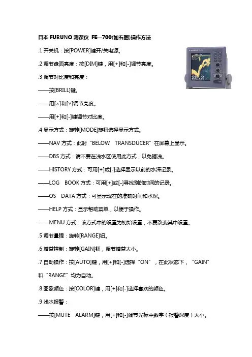
5.他船信息显示
两种显示方式:PLOTTER,LIST,按LIST方式显示, 按MENU及2键选择标绘PLOTTER方式显示,
TARGET DATA列表显示方式:
分别显示NAME、RNG、BRG为船名、距离、方位的列表,上下键在列
表间移动,需要调取某船信息时移动到此船后按.可根据方位距离查找调取相应船的动态数据
按DANGEROUS SHIP LIST,显示CPA/TCPA报警的船舶列表
PLOTTER图形标绘显示方式。
第一章日本FURUNO古野公司生产的GMDSS中频/高频(MF/HF)组合电台主要有三种型号,150W的FS-1570组合电台,250W的FS-2570组合电台和400W的FS-5000组合电台,下面以FURUNO FS-2570 MF/HF组合电台为例介绍FURUNO组合电台的功能。
POWER(电源开关):开启/断开电源。
DISTRESS(遇险按钮):按住此按钮三秒以上发射遇险报警。
开始按时灯闪,大于三秒后灯亮。
收到遇险应答电报后灯灭。
如果按住此按钮少于三秒不会发射遇险报警。
CALL:发射除遇险外的呼叫。
ENTER KNOB(输入按钮和选择旋钮):无线电话时,旋转改变TX/RX信道、灵敏度、音量等,按一下是输入功能;DSC时,旋转选择菜单项目,按一下是输入功能。
CANCEL:取消错误的数据,恢复先前的菜单,消除音响报警,取消发射,删除错误信息。
1/RT/2182:按一下从平时值守的DSC屏幕转换到SSB无线电话设置屏幕,连续按两秒以上直接转换到的遇险无线电话通信屏幕。
2/DSC:编辑DSC发射电文。
3/TEST:进行日常试验。
4/IntCom:接通/关闭与其他控制单元FS-2570C的内部通信。
5/ACK/SQ:在DSC时,改变是自动发收妥通知还是手动发收妥通知,关键点,一般不要使用自动发收妥通知,因为这样会使操作员错过许多呼叫;在SSB时,打开/关闭静噪功能。
6/SCAN:在DSC的值守屏幕,启动/停止在DSC频率上的扫描值守功能。
7/喇叭:接通/断开喇叭。
8/PRINT:打印通信日志文件、当前显示屏(除DSC准备状态屏幕和无线电话屏幕)和测试结果。
9/灯光:调节面板亮度和液晶显示器(LCD)的对比度。
FILE/CURSOR:在DSC准备屏幕打开已存储的发送文件夹,选择要发送的电文;移动光标。
#/SET UP:打开设置菜单。
ALARM灯:遇险和紧急呼叫闪红灯;安全和日常呼叫闪绿灯。
OVEN灯:当主配电板电源接通时亮绿灯。
按POWER键接通/关闭电源。
调整面板亮度和液晶显示器的对比度。
按[9/灯光]键显示亮度/对比度调节窗口;转动[ENTER]旋钮选择亮度(DIMMER)一栏,按一下[ENTER]确认,再转动[ENTER]旋钮选择亮度等级,按一下[ENTER]确认;转动[ENTER]旋钮选择对比度(CONTRAST)一栏,按一下[ENTER]确认,再转动[ENTER]旋钮选择对比度等级,按一下[ENTER]确认;转动[ENTER]旋钮选择退出(EXIT)一栏,按一下[ENTER]退出该窗口。
调整喇叭音量。
按[7/喇叭]一次分别接通或关闭喇叭和日常电报的喇叭报警;按一下[1/RT/2182]键,切换到无线电话显示屏;转动[ENTER]旋钮选择音量(VOL)一栏,按一下[ENTER]确认,再转动[ENTER]旋钮选择音量等级,按一下[ENTER]确认所选的音量。
扫描DSC频率。
在DSC显示屏,按[6/SCAN]扫描值守6个DSC频率或值守在单个DSC频率上。
船位和时间输入。
正常情况下,都接有GPS信号,船位和时间是自动输入。
只有在GPS信号丢失时,才需要按下面的步骤手动输入船位和时间。
在DSC显示屏,按[#/SET UP]键调出设置菜单[Setup menu];转动[ENTER]旋钮选择位置(POSITION)一栏,按一下[ENTER]调出位置设置菜单[Position setup];在输入方式[INPUT TYPE]一栏按一下[ENTER],转动[ENTER]旋钮选择手动[MANUAL],再按一下[ENTER]确认;在纬度[LAT]一栏按一下[ENTER]调出纬度输入窗口,输入正确的纬度后按 [ENTER]确认,在最右坐标位[1]键是北纬 [2]键是南纬;在经度[LON]一栏按一下[ENTER]调出经度输入窗口,输入正确的经度后按 [ENTER]确认,在最右坐标位[1]键是东经[2]键是西经;在时间[TIME]一栏按一下[ENTER]调出时间输入窗口,输入正确的时间后按 [ENTER]确认,此时会返回到先前的设置菜单[Setup menu];按[CANCEL]键返回到DSC显示屏。
第三节选择发射模式[MODE]。
按[1/RT/2182]键调出无线电话显示屏,转动[ENTER]旋钮在[MODE]一栏选定“SSB”;选择波段。
转动[ENTER]旋钮到[CH]一栏,按一下[ENTER]调出波段输入窗口;用光标键[FILE/CURSOR]将光标放在左边第一位数上,转动[ENTER]旋钮选择所要的“2、4、6、8、12、16、18、25MHz”波段,按一下[ENTER]确认;或直接输入国际电联规定的成对频道:例如“1225”按[ENTER]输入,就可以输入广州台的成对频率。
在选定的波段输入相应的发射和接收频率。
转动[ENTER]旋钮到[TX]一栏,按一下[ENTER]调出频率输入窗口,用数字键输入所要的发射频率,按一下[ENTER]确认;转动[ENTER]旋钮到[RX]一栏,按一下[ENTER]调出频率输入窗口,用数字键输入所要的接收频率,按一下[ENTER]确认。
关键点1:国际用于遇险无线电话通信的频率是、、、、、,禁止在这些频率上进行日常通信,因此日常通信时在输入发射和接收频率时不能使用以上频率。
关键点2:输入频率之前,首先要查无线电信号书第一册(ALRS VOL 1),岸台的发射频率就是船台的接收频率,岸台的接收频率就是船台的发射频率。
输入接收频率后要注意聆听接收效果,如果效果太差,马上换到其它波段。
转动[ENTER]旋钮到“LOW、 MID、 HIGH”选择所要的发射功率。
启动发射自动调谐。
按一下话筒上的按下讲话[PTT]开关出现“TX”,或按面板上的[0/LOG/TUNE]键出现“TUNE”,即可启动自动调谐。
新选择的频率在2到5秒之内完成调谐,调谐过的频率少于秒。
当调谐成功完成时,显示TUNE:OK 。
当调谐失败时,显示TUNE:NG 。
关键点:远洋船员兄弟长期远离祖国和亲人,在海上每逢佳节倍思亲的时候,单边带无线电话就成了在空中连接爱情、亲情、友情的桥梁,因此单边带无线电话是目前组合电台使用最多的一项功能。
每当过年过节,岸台特别拥挤,排队特别长,经常更换频道。
在心情着急的时候,每一次更换频率后,千万要注意调谐是否OK,如果调谐不好,不能长时间按发射,因为此时根本叫不通岸台,很容易造成发射电路损坏。
调节接收的高频增益(灵敏度)转动[ENTER]旋钮到荧光屏下边的[SEN]一栏,按一下[ENTER]调出调整窗口,再边转动[ENTER]旋钮边听接收的效果,在自己觉得比较好的位置,按一下[ENTER]确认;一般情况下放在最大。
完成上面操作,就可以进行单边带无线电话通信。
第四节数字选择性呼叫(DSC)菜单介绍在单独呼叫(INDIVIDUAL)时,输入所要呼叫的对方九位识别码。
这一栏是确定完成数字选择性呼叫(DSC)后,建立后续使用的通信种类。
TELEPHONE:全抑制(J3E)单边带无线电话NBDP-ARQ:ARQ窄带直接印字电报,这是每一个语句自动请求重发纠错的NBDP工作种类,用于两个单独台之间的通信。
NBDP-FEC:FEC窄带直接印字电报,这是前向纠错方式的NBDP工作种类,用于向很多台广播的通信。
4.1.5 第五栏通信频率(COM. FREQ)在这里输入与上一栏相对应的后续工作频率。
关键点:在遇险呼叫时,使用国际遇险频率;在正常的日常呼叫时,禁止使用国际遇险频率。
在这一栏输入要使用的选择性呼叫的频率。
关键点:要选用有人守听的频率,经验是船台和岸台在守听的比较多,岸台其它频率请查阅无线电信号书第一册和第五册。
4.1.7 结束码(END OF SEQUENCE)在这一栏有三种结束码:ACK RQ (Acknowledge Request):要求收妥通知,是要求对方当收到呼叫时给收妥通知。
一般用于单呼和测试。
ACK BQ (Acknowledge Back):收妥返回。
是对ACK RQ 的回复。
在与岸台测试时就能收到岸台给的ACK BQ,只有收到ACK BQ才表示测试完成。
EOS (End of Sequence):结束码,不需要对方给收妥通知,一般用于群呼。
DSC遇险操作4.2.1 发DSC遇险呼叫第一种方法是按[DISTRESS]按钮发射未指明遇险性质的遇险报警:1)打开 [DISTRESS]按钮盖,按住[DISTRESS]按钮三秒钟以上,[DISTRESS]按钮的指示红灯开始闪,并且蜂鸣器发出声响,此时可以松开按钮;2)发射遇险报警过程大约需要40秒钟,在显示屏底部显示发射完成需要的秒数。
此时,无线电话输出功率自动设置为最大;3)在遇险报警发射后,音响报警停止,红灯仍亮着,必须等分钟至分钟以便岸台给遇险收妥通知。
此时,设备除了接收遇险报警收妥通知外不接收其它任何呼叫,发射的遇险报警呼叫记录在TX log里。
在五分钟后如没有收到岸台的遇险收妥通知,重发DSC遇险报警;4)当收到岸台的遇险收妥通知,音响报警声响,按[CANCEL]键停止音响报警。
无线电话自动地设置在遇险收妥通知指定的工作频率和发射种类上,用无线电话与岸台进行遇险通信“MAYDAY MAYDAY MAYDAY THIS IS……”。
第二种方法是发指明遇险性质的遇险报警:1)打开 [DISTRESS]按钮盖,短暂地按一下[DISTRESS]按钮,调出遇险报警编辑屏幕菜单;2)转动[ENTER]旋钮到[NATURE]栏选择遇险性质,然后按[ENTER]输入;3)转动[ENTER]旋钮到[POS.]栏打开输入船位菜单,自动或手动根据提示输入船位,在最右坐标位[1]键是北纬或东经[2]键是南纬或西经;紧接着输入时间;4)转动[ENTER]旋钮到[COM. TYPE]栏,选择TELEPHONE或NBDP-FEC,然后按[ENTER]输入;5)转动[ENTER]旋钮到[DSC FREQ]栏,选择要用的DSC频率,一般首先是使用,然后按[ENTER]输入;(如果遇险报警未被收妥,设备会自动在2MHZ 8MHZ 16MHZ 4MHZ 12MHZ 6MHZ的遇险和安全频率上重发本遇险报警)6)转动[ENTER]旋钮到GO TO ALL VIEW按[ENTER],再转动[ENTER]旋钮到END OF SEQUENCE 栏按[ENTER],选择ACK RQ按[ENTER];7)按住[DISTRESS]按钮三秒钟以上,开始发射遇险报警,按上一种方法介绍的国际遇险通信操作程序进行遇险通信。
8)编辑指明遇险性质4.2.2●在2182KHZ上连续值守,等候岸台发射遇险收妥呼叫,直到收到宣布遇险通信结束“SEELONCE FINI”;●如果多次收到同一条船发射的遇险报警,并且毫无疑问在你船附近,经船长同意,你船能提供帮助,在与救助协调中心RCC或岸台商量后可以在2182KHZ上用无线电话发送遇险收妥通知和在用DSC发送遇险收妥通知;●一条船在中频频道上接收到遇险报警,绝不允许发射遇险转发呼叫;船舶在2MHZ收到DSC遇险报警流程图没有收到他船的遇险转发;没有收到他船的无线电话或NBDP遇险通信;你在遇险船附近,而遇险船不能够发送遇险报警;你轮船长或负责人认为有必要进一步的援助。