DS6708入门指南(简体中文)
- 格式:pdf
- 大小:1.55 MB
- 文档页数:2


HD 4 Channel and 8 ChannelDigital Video RecorderQuick Start Guide 8200-1368-01 A0NoticePlease read this manual thoroughly and save it for future use before attempting to connect or operatethis unit.The information in this manual was current when published. The manufacturer reserves the right torevise and improve its products. All specifications are therefore subject to change without notice. CopyrightUnder copyright laws, the contents of this manual may not be copied, photocopied, reproduced,translated or reduced to any electronic medium or machine-readable form, in whole or in part, withoutprior written consent of Tyco Security Products. © 2016 Tyco Security Products. All rights reserved.Customer ServiceThank you for using Tyco Security Products. We support our products through an extensive worldwide network of dealers. The dealer through whom you originally purchased this product is your point ofcontact if you need service or support. Our dealers are empowered to provide the very best incustomer service and support. Dealers should contact Tyco Security Products at (800) 507-6268 or(561) 912-6259 or on the Web at TrademarksThe trademarks, logos, and service marks displayed on this document are registered in the UnitedStates [or other countries]. Any misuse of the trademarks is strictly prohibited and Tyco SecurityProducts. will aggressively enforce its intellectual property rights to the fullest extent of the law,including pursuit of criminal prosecution wherever necessary. All trademarks not owned by TycoSecurity Products. are the property of their respective owners, and are used with permission or allowed under applicable laws.Product offerings and specifications are subject to change without notice. Actual products may varyfrom photos. Not all products include all features. Availability varies by region; contact your salesrepresentative.Table of ContentsImportant Safeguard and Warning (4)Front Panel – 4 channel and 8 channel (6)Rear Panel (7)Local Login (8)Web (9)Important Safeguard and Warning All installation and operation here should conform to your local electrical safety codes.We assume no liability or responsibility for all the fires or electrical shock caused by improper handling or installation.We are not liable for any problems caused by unauthorized modifications or attempted repair.Improper battery use may result in fire, explosion, or personal injury!When replaceing the battery, please make sure you are using the same model!NoteAll installation and operations should conform to your local electric safety rules.1.Check Unpacked DVRWhen you receive the DVR, please check whether there is any visible damage. The protective materials used for the package of the DVR can protect most accidental clashes duringtransportation. Then you can open the box to check the accessories.Please check the items in accordance with the list on the warranty card (Remote control isoptional). Finally you can remove the protective film of the DVR.2. About Front Panel and Rear PanelThe model in the front panel is very important; please check according to your purchase order.The label in the rear panel will contain the serial number. Usually we need you to present the serial number when we provide the service after sales.3. HDD InstallationThis series DVR has only one SATA HDD. Please use HDD of 7200rpm or higher.Please follow the instructions below to install hard disk.CAUTIONShut down the device and then unplug the power cable before opening the case to replace the HDD.1. Loosen the screws of the uppercover and side panel.2. Fix four screws in the HDD.3. Place the HDD in accordance withthe four holes in the bottom.4. Turn the device upside down and then turn the screws in firmly .5. Connect the HDD cable andpower cable. 6. Put the cover in accordance with theclip and then place the upper cover back. Secure the screws in the rear panel and the side panel.Note:You can connect the HDD data cable and the power cable first and then fix the HDD in the device.Please pay attention to the front cover. It adopts the vertical sliding design. You need to push the clip first and then put down.Front Panel – 4 channel and 8 channel The front panel is shown in Figure 1.Figure 1Please refer to the following sheet for front panel button information.Rear Panel The following figure is using the 8 channel for illustration. See Figure 2.Figure 2Please refer to the following sheet for detailed information.Local Login After system booted up, default video display is in multiple-window mode.Click Enter or left click mouse, you can see the login interface. See Figure 3.System consists of three accounts:●Username: admin. Password: admin. (administrator, local and network)●Username: default. Password: default. (hidden user) Hidden user “default” is for system interioruse only and cannot be deleted. When there is no login user, hidden user “default” automatically login. You can set some rights such as monitor for this user so that you can view some channel views without login.Note:●For security reason, please modify password after you first login.●You can set to lock an account or not, password login attempt times, and account lock time.Figure 3WebOpen IE and input DVR address in the address column. For example, if your DVR IP is 10.10.3.16, then please input http:// 10.10.3.16 in IE address column.The system pops up a warning to ask you whether to install webrec.cab control or not. Please clickthe yes button.If you can’t download the ActiveX file, please modify your IE security setup.After installation, the interface is shown as below. See Figure 4.Please input your user name and password.Default factory name is admin and password is admin.Note:For security reasons, please modify your password after you first login.Figure 4Note●This quick start guide is for reference only. Slight difference may be found in the user interface.●All the designs and software here are subject to change without prior written notice.●All trademarks and registered trademarks mentioned are the properties of their respectiveowners.●If there is any uncertainty or controversy, please refer to the final explanation of us.●Please visit our website or contact your local service engineer for more information.。

DS-6700系列音视频编码器快速指南关于本手册本手册描述的产品仅供中国大陆地区销售和使用。
本手册作为指导使用。
手册中所提供照片、图形、图表和插图等,仅用于解释和说明目的,与具体产品可能存在差异,请以实物为准。
因产品版本升级或其他需要,本公司可能对本手册进行更新,如您需要最新版手册,请联系我们。
我们建议您在专业人员的指导下使用本手册。
责任声明●在法律允许的最大范围内,本手册所描述的产品(含其硬件、软件、固件等)均“按照现状”提供,可能存在瑕疵、错误或故障,本公司不提供任何形式的明示或默示保证,包括但不限于适销性、质量满意度、适合特定目的、不侵犯第三方权利等保证;亦不对使用本手册或使用本公司产品导致的任何特殊、附带、偶然或间接的损害进行赔偿,包括但不限于商业利润损失、数据或文档丢失产生的损失。
●若您将产品接入互联网需自担风险,包括但不限于产品可能遭受网络攻击、黑客攻击、病毒感染等,本公司不对因此造成的产品工作异常、信息泄露等问题承担责任,但本公司将及时为您提供产品相关技术支持。
●使用本产品时,请您严格遵循适用的法律。
若本产品被用于侵犯第三方权利或其他不当用途,本公司概不承担任何责任。
●如本手册内容与适用的法律相冲突,则以法律规定为准。
前言本节内容的目的是确保用户通过本手册能够正确使用产品,以避免操作中的危险或财产损失。
在使用此产品之前,请认真阅读产品手册并妥善保存以备日后参考。
概述本手册描述了产品各功能的使用方法。
本手册适用于以下产品:关于默认●设备出厂默认的超级管理员账号:admin。
●设备出厂默认的IPv4地址:192.168.1.64。
描述内容约定在本手册中为了简化描述,做以下约定:●本手册提及的“设备”主要指音视频编码器。
●本手册提及的“DVS”指的是音视频编码器。
●本手册提及的“IP设备”主要指的是网络摄像机(IPC)、网络球机(IP DOME)。
●本手册提及的“通道”泛指音视频编码器的模拟视频通道(Camera)。
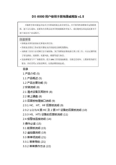
DS-8000系列网络硬盘录像机用户使用手册(V1.5版)一、DS-8000HS后面板说明❶❷❸❹❺❻❼❽序号物理接口连接说明1视频输入(VIDEO IN)连接(模拟)视频输入设备,标准BNC接口。
环通输出(AUDIO IN)连接监视器,视频环通输出。
2 视频输出(AUX VOUT)连接监视器,4个副口视频输出。
3 视频输出(VOUT)连接监视器,本地视频及菜单输出。
4 VGA接口连接VGA显示设备,如电脑VGA显示器等。
5 键盘接口(KEYBOARD)2个,任意选择其中一个用于连接(485)控制键盘,使用RJ45接口的3、4线(接收信号)接控制键盘的D+、D-;另外一个用于设备间的级联,级联的设备两端均使用RJ45接口的3、4线。
RS-232接口连接RS-232设备,如调制解调器、电脑等。
设备配件盒内提供了连接线。
UTP网络接口连接以太网络设备,如以太网交换机、以太网集线器(HUB)等。
6 RS-485接口连接RS-485设备,如解码器等。
使用绿色弯针的插座,4针分别是T+、T-、R+、R-,其中1、2线(发送信号)接解码器等。
7报警输入(IN)接开关量的报警输入。
报警输出(OUT)接开关量报警输出。
8 电源通过开关可以选择输入的交流电压为220V或110V。
二、DS-8000HS/HTS前面板说明❶❷❸❹❺❻❼❽序号类型名称说明1 状态灯1-16 通道1-16状态显示。
绿色表示正在录像,红色表示正在网传,橙色表示正在录像和网传。
指示灯闪烁并呈红色,表示对应序号的硬盘有错误。
2 液晶显示屏信息显示。
3 复合键MENUESCEDITAINFO 1、预览界面到菜单操作界面的切换;2、雨刷控制快捷键【WIPER】。
取消当前操作,返回到上级菜单。
1、进入编辑状态,在编辑状态下用于删除光标前字符;2、光圈控制键【IRIS+】;3、选择框状态✓与×之间的切换。
1、输入法(数字、英文、中文、符号)之间的切换;2、焦距控制键【FOCUS+】;3、本地预览界面中,显示/隐藏通道状态。
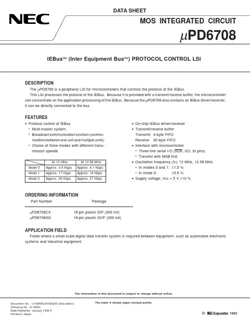
µPD6708 IEBus™ (Inter Equipment Bus™) PROTOCOL CONTROL LSIDocument No.U10680EJ2V0DS00 (2nd edition) (Previous No. IC-3282)Date Published January 1996 PPrinted in Japan The information in this document is subject to change without notice.The mark 5 shows major revised points.DESCRIPTIONThe µPD6708 is a peripheral LSI for microcontrollers that controls the protocol of the IEBus.This LSI processes the protocol of the IEBus. Because it is provided with a transmit/receive buffer, the microcontroller can concentrate on the application processing of the IEBus. Because the µPD6708 also contains an IEBus driver/receiver, it can be directly connected to the bus.FEATURES•Protocol control of IEBus•Multi-master system•Broadcast communication function (commu-nication between one unit and multiple units)•Choice of three modes with different trans-mission speedsAt 12 MHz At 12.58 MHzMode 0Approx. 3.9 Kbps Approx. 4.1 KbpsMode 1Approx. 17 Kbps Approx. 18 KbpsMode 2Approx. 26 Kbps Approx. 27 KbpsORDERING INFORMATIONPart Number PackageµPD6708CX16-pin plastic DIP (300 mil)µPD6708GS16-pin plastic SOP (300 mil)•On-chip IEBus driver/receiver•Transmit/receive bufferTransmit:4-byte FIFOReceive:20-byte FIFO•Interface with microcontroller•Three-line serial I/O (SCK, SO, SI pins)•Transfer with MSB first•Oscillation frequency (f X): 12 MHz, 12.58 MHz •In modes 0 and 1:±1.5 %•In mode 2:±0.5 %•Supply voltage: V DD = 5 V ±10 %APPLICATION FIELDFields where a small-scale digital data transfer system is required between equipment, such as automobile electronic systems and industrial equipment1993©PIN CONFIGURATION (TOP VIEW)• 16 pin plastic DIP (300 mil)µPD6708CX• 16 pin plastic SOP (300 mil)µPD6708GSSCK:Serial clock inputSI:Serial data inputSO:Serial data outputIRQ:Interrupt request outputR/W:Read/write switchover inputXI, XO:System clockGND:GroundBUS–, BUS+:IEBus input/outputAV DD:IEBus analog power supply (connected to V DD pin)C/D:Command/data switchover inputCS:Chip select inputRESET:Reset inputTEST:Test input (connected to V DD pin)V DD:Positive power supply2CONTENTS1.PIN FUNCTIONS (5)1.1List of Pin Functions (5)2.IEBus OPERATION (6)2.1Operation Overview (6)2.2IEBus Communication Protocol (7)2.2.1Bus mastership determination (arbitration) (8)2.2.2Communication modes (8)2.2.3Communication address (9)2.2.4Broadcast communication (9)2.3Transfer Protocol (10)2.4Transfer Data (Contents of Data Field) (16)2.5Bit Format (19)3.INTERNAL CONFIGURATION (20)3.1Data Link Layer Controller (21)3.2Physical Layer Controller (21)3.3IEBus Driver/Receiver (21)3.4Host Interface (21)4.INTERFACING WITH HOST CONTROLLER (22)4.1Accessible Buffers and Registers from Host Controller (22)4.1.1Write data buffer (WDB) (22)4.1.2Read data buffer (RDB) (22)4.1.3Command register (CMR) (22)4.1.4Status register (STR) (23)4.2Host Interface Modes (23)4.2.1Switching through pin control (24)4.2.2Switching through software control (26)4.3Reset Mode (28)MUNICATION CONTROL COMMANDS (30)5.1Overview of Communication Control Commands (30)5.2Communication Control Command Functions (31)5.2.1INIT command (command code: 0000) (31)5.2.2SETSA command (command code: 0001) (32)5.2.3MREQ1 command (command code: 0010) (33)5.2.4MREQ2 command (command code: 0011) (34)5.2.5ABORT command (command code: 0100) (34)5.2.6SETSD command (command code: 0101) (35)5.2.7GETSTA command (command code: 0110) (36)5.2.8SETREV command (command code: 0111) (37)6.RETURN CODES (38)6.1Return Codes in Master/Slave Data Transmission (38)6.2Return Codes in Master Reception (38)6.3Return Codes in Slave Reception (39)6.4Return Codes in Broadcast Reception (39)6.5Return Codes Generation Intervals (40)MUNICATING WITH HOST CONTROLLER (43)7.1Master Transmission (43)7.1.1Master transmission by MREQ1 command (43)7.1.2Master transmission by MREQ2 command (44)347.2Slave Transmission (44)7.2.1Data transmission (44)7.2.2Transmitting slave status address and lock address (45)7.3Master Reception (45)7.4Slave Reception (46)7.5Broadcast Reception (47)8.EXAMPLE OF HOST CONTROLLER PROCESSING FLOW (48)8.1Main Routine (48)8.2Interrupt Service Routine (49)8.3Processing Routine (50)8.3.1µPD6708 initialization routine (50)8.3.2Communication control command processing routine (51)8.3.3Master transmission processing routine (57)8.3.4Slave data transmission processing routine (58)8.3.5Master reception processing routine (59)9.ELECTRICAL SPECIFICATIONS (63)10.PACKAGE DRAWINGS (67)11.RECOMMENDED SOLDERING CONDITIONS (69)APPENDIX MAJOR DIFFERENCES BETWEEN µPD6708 AND µPD72042A, µPD72042B (70)1.PIN FUNCTIONS1.1List of Pin FunctionsPin No.Pin Name Input/Output Function I/O Format At Reset1SCK Input Input for serial clock used to interface with microcontroller.CMOS input Input2SI Input Input for serial data used to interface with microcontroller.CMOS input Input3SO Output Output for serial data used to interface with microcontroller.CMOS output High level4IRQ Output Output used by interrupt request signals generated by CMOS output Low levelcommunication and command execution results.Used as operation start request signal to microcontroller.The interrupt request signal is output for 8 µs or longerat high level.5R/W Input Input for switching serial interface read/write mode.CMOS input InputWhen high, it is in the read mode. When low, it is in thewrite mode.When this pin is low and C/D pin high, the read and writemodes can be switched by commands input from the serialinterface.6XI––Connection pins for system clock resonator.––(Oscillation 7XO Use a 12- or 12.58-MHz crystal, or ceramic resonator.continues)Frequency precision depends on the communication modeused.Mode 0:±1.5 %Mode 1:±1.5 %Mode 2:±0.5 %8GND––Ground––––9BUS–Input/output Input/output for IEBus.––High10BUS+impedance 11AV DD––IEBus driver/receiver analog power supply. Connect to V DD.––––12C/D Input Input used to switch between processing data input to the CMOS input Inputserial interface as commands or data.When set to high, data is processed as commands; whenlow, data is processed as data.When this pin is high and R/W pin low, the read and writemodes can be switched by commands input from the serialinterface.13CS Input Chip select input.CMOS input InputWhen low, serial interface input is enabled.When high, serial clock (SCK) input is disabled, SO pinbecomes high impedance, and the serial clock counter isreset.The status of CS pin is not affected by IEBus transmit andreceive operations.14RESET Input System reset signal input pin.CMOS input InputLow input effects a reset.Always input the low signal for 6 µs or longer after turningon the power.15TEST Input Always connect this pin to the V DD.CMOS input––16V DD––Positive power supply input. Apply a voltage of 5 V ±10 %.––––562.IEBus OPERATION2.1Operation OverviewThe µPD6708 is an IEBus interface CMOS LSI device.The IEBus is a bus for a small-scale digital data transfer system designed to transfer data between electronic devices.The µPD6708 is connected to a microcontroller incorporated in electronic equipment with a serial interface (SCK, SO,SI pins). The data and commands required to transfer data with the host controller (microcontroller) are set via this serial interface.When the host controller transmits data to the µPD6708 via the serial interface, signals are output from the BUS pins (BUS+ and BUS–). Data received from the BUS pins can be read by the host controller via the serial interface.572.2 IEBus Communication Protocol An overview of the IEBus is as follows.•Communication system: Half-duplex asynchronous communication •Multi-master systemAll the units connected to the IEBus can transfer data to the other units.•Broadcast communication function (communication between one unit and multiple units)Group broadcast communication:Broadcast communication with group units General broadcast communication:Broadcast communication with all units.•Three modes with different transfer speeds selectable.f X = 12 MHzf X = 12.58 MHzMaximum Number of Transfer Bytes(bytes/frame)Mode 0Approx. 3.9 Kbps Approx. 4.1 Kbps 16Mode 1Approx. 17 Kbps Approx. 18 Kbps 32Mode 2Approx. 26 KbpsApprox. 27 Kbps128•Access control: CSMA/CD (Carrier Sense Multiple Access with Collision Detection)The priority order for bus occupancy is as follows.<1>Broadcast communication takes precedence over ordinary communication (i. e., communication between one unit and another).<2>The lowest master address has the highest priority.•Communication scale Number of units:MAX. 50Cable length:MAX. 150 m (with twisted-pair cable <Resistance: 0.1 Ω/m or less>)Load capacity:MAX. 8000 pF <between BUS– and BUS+>, f X = 12 MHz MAX. 7100 pF <between BUS– and BUS+>, f X = 12.58 MHzTerminating resistor:120 Ω582.2.1 Bus mastership determination (arbitration)When a unit connected to the IEBus controls another unit, it performs an operation to occupy the bus. This operationis called arbitration.Arbitration is to select one unit, and if several units begin to transmit data simultaneously, gives permission to occupy the bus to that one unit.So that one unit is granted the permission to occupy the bus as a result of the arbitration, the following priority conditions are determined.RemarkThe units not given permission through arbitration are automatically allowed to get into retransfer mode (number of retransfer times for the µPD6708: 3).(1)Priority according to type of communicationBroadcast communication (between a single and multiple units) takes precedence over ordinary communication (between single units).(2)Priority according to master addressIf the communication devices are of the same type, the unit with the lowest master address has the highest priority.ExampleThe master address comprises 12 bits, and unit 000H has the highest priority while unit FFFH has the lowest priority.2.2.2 Communication modesThe IEBus is provided with three communication modes with different transfer speeds. The transfer speed and maximum number of transfer bytes in a single communication frame in each communication mode are shown in Table 2-1.Table 2-1. Transfer Speed and Maximum Number of Transfer Bytes in Each Communication ModeCommunication ModeMaximum Number of Transfer Bytes (bytes/frame)Actual Transfer Speed Note 1 (Kbps)f X = 12 MHz Note 2f X = 12.58 MHz Note 2016Approx. 3.9Approx. 4.1132Approx. 17Approx. 182128Approx. 26Approx. 27Notes 1.Actual transfer speed when the maximum number of bytes is transferred2.Oscillation frequency when the µPD6708 is usedCautions 1. A communication mode is selected for each unit connected to the IEBus before communication isperformed. If the communication mode of the master unit is not the same as that of the unit withwhich the master unit is to communicate (slave unit), communication cannot be performed correctly.2.If the oscillation frequency of one unit is fx = 12 MHz and that of the other unit is fx = 12.58 MHz,communication cannot be performed correctly even if the communication mode is the same. Make sure that the oscillation frequencies of the two units to communicate are the same.592.2.3 Communication addressWith the IEBus, a 12-bit communication address is assigned to each unit. The communication address is made up as follows.Higher 4 bits:Group number (number which identifies the group to which the unit belongs)Lower 4 bits:Unit number (number which identifies a unit within a group)2.2.4 Broadcast communicationIn ordinary communication, there is only one master unit and one slave unit, and transmission or reception is performed on an one-to-one basis. In broadcast communication, however, there are a number of slave units and the master unit performs transmission with these slave units. Because there are several slave units, no acknowledge signals is returned from the slave units during communication.Whether broadcast communication or ordinary communication is performed is specified by the broadcast bit (for the broadcast bit, see 2.3 (1) <2> “Broadcast bit”).There are two kinds of broadcast communication, as follows.(1) Group broadcast communicationBroadcast communication is performed to the units in a group whose group numbers are the same as that specified by the higher 4 bits of the communication address.(2) General broadcast communicationBroadcast communication is performed to all units irrespective of their group numbers.Group broadcast communication or general broadcast communication is identified by the value of a salve address (for the slave address, see 2.3 (3) “Slave address field”).5102.3 Transfer ProtocolThe IEBus transfer signal format is shown in Figure 2-1.Data is transferred as a series of signals called a communication frame. The number of data that can be transferred in one communication frame and the transfer speed differ depending on the communication mode.Figure 2-1. Transfer Signal FormatP:Parity bit (1 bit)A:Acknowledge bit (1 bit)When A = 0: ACK When A = 1: NAK N:Number of data bytes RemarkIn broadcast communication, the value of the acknowledge bit is ignored.(1)HeaderA header comprises a start bit and a broadcast bit, as described below.<1>Start bitThe start bit is a signal which tells the other units that data transmission will start.The unit which is about to start transmitting data will output the low signal (the start bit) for a specified time, and then outputs the broadcast bit.If another unit is already outputting a start bit before one unit outputs a start bit, the unit will not output the start bit.It will wait until the another unit completely outputs the start bit, and then outputs the broadcast bit.The units other than the one that has started transmission detect this start bit and enters the reception state.<2>Broadcast bitThe broadcast bit distinguishes between broadcast communication and ordinary communication.When this bit is ‘0’, it indicates broadcast communication; when it is ‘1’, it indicates ordinary communication. There are two types of broadcast communication: group broadcast and general broadcast. These types are identified by the value of the slave address (for the slave address, see (3) “Slave address field”).In broadcast communication, there are a number of slave units. Therefore, the acknowledge bit is not returned in the fields described in (2) below and onward.If two or more units start to transmit a communication frame simultaneously, broadcast communication takes precedence over ordinary communication, and wins in the arbitration.5Field Name Number of BitsTransfer TimeMode 0Mode 1Mode 2Header Master Address Field Slave AddressField Control Field MessageLength Field Data Field112111211411811811811Start Bit Broad-cast Bit Master AddressP Slave Address PA Control BitPA Message Length BitPADataBitPAData BitPAApprox. 7330 s µApprox. 2090 s µApprox. 1590 sµApprox. 1590× N s µApprox. 410× N s µApprox. 300× N sµ(f x = at 12 MHz)(2)Master address field5 The master address field is used to transmit the unit address of the master unit (master address) to the other units.The master address field consists of master address bits and a parity bit.The master address comprises 12 bits and is output from the MSB.If two or more units start transmitting the broadcast bit of the same value simultaneously, the arbitration decision is madeby the master address field.The master address field compares the data the master has output with the data on the bus each time the master transmits1 bit of data. If the master address output by the master unit is different from the data on the bus, the master unit assumesthat it has lost in arbitration, stops transmission, and enters the reception state.Because the IEBus has a wired-AND configuration, the unit having the lowest master address of the units participatingin the arbitration (arbitration masters) wins in the arbitration. Ultimately, only one unit remains in the transmission stateas the master unit after outputting a 12-bit master address.This master unit then outputs a parity bit Note, makes the other units confirm the master address, and then outputs the slave address field.Note Even parity is used. When the number of the bits that are ‘1’ in the master address is odd, the parity bit is ‘1’.(3)Slave address fieldThe slave address field is used to transmit the address (slave address) of a unit (slave unit) with which the master wishesto communicate.The slave address field consists of slave address bits, a parity bit, and an acknowledge bit.The slave address comprises 12 bits and is output from the MSB. After the 12-bit slave address is transmitted, the paritybit is output to prevent the slave address from being received incorrectly. Next, the master unit looks for the acknowledge signal (bit) from the slave unit to confirm that the slave unit exists on the bus. When the master unit detects the acknowledge signal, it starts outputting the control field. In the case of broadcast communication, however, the master unit outputs the control field without waiting for the acknowledge bit.A slave unit outputs the acknowledge signal if it has detected that its slave address coincides with that selected by the master and that the parities of both the master and slave addresses are even. If the parity is odd, the slave unit assumesthat the master or slave address has not been correctly received, and does not output the acknowledge signal. In this case,the master unit enters the standby (monitor) state and communication ceases.In the case of broadcast communication, the slave address is used to distinguish between group broadcast and general broadcast as follows:Slave address = FFFH:General broadcast communicationSlave address ≠ FFFH:Group broadcast communicationRemark In the case of group broadcast communication, the group number is the value of higher 4 bits of the slave address.(4)Control fieldThe control field indicates the type of data and the transfer direction of the subsequent data field.5The control field consists of 4 control bits, a parity bit, and an acknowledge bit.The control bits are output from the MSB.A parity bit is output after the control bits. When the parity is even and the slave can execute the function requestedby the master unit, the slave unit outputs an acknowledge signal, and then outputs the next message length field. If the slave unit cannot execute the function requested by the master unit even if the parity is even, or if the parity is odd, the slave unit does not output the acknowledge signal but returns to the standby (monitor) state.After the master unit has confirmed the acknowledge signal, it starts outputting the next message length field.If the master unit is cannot confirm the acknowledge signal, it enters the standby state and stops communication. In the case of broadcast communication, however, the master unit starts outputting the message length field without confirming the acknowledge signal.For the functions of the control bits, see Table 2-3.(5)Message length fieldThe message length field is used to specify the number of communication data bytes.The message length field comprises 8 message length bits, a parity bit and, an acknowledge bit.The message length bits are output from the MSB. The message length bits indicate the number of communication data bytes as shown in Table 2-2.Table 2-2. Meaning of Message Length BitsMessage Length Bits (hex)Number of Transmission Data Bytes01H 1 byte02H 2 bytes::::FFH255 bytes00H256 bytesRemark In the communication mode, if the number of bytes exceeding the maximum number of transfer bytes per frame is set, two or more frames are communicated. In this case, the message length bits indicate the number ofremaining communication data bytes during the second communication and onward.The operation of this field differs depending on whether the master transmits (bit 3 of control bits is 1) or receives (bit3 of control bits is 0) data.<1>When master transmits dataThe message length bits and parity bit are output by the master unit. The slave unit outputs the acknowledge signal and then the next data field if it detects that the parity is even. The slave unit does not output the acknowledge signal in the case of broadcast communication.If the parity is odd, the slave unit assumes that the message length bits have not been received correctly, and returns to the standby (monitor) state without outputting the acknowledge signal. In this case, the master unit also returns to the standby state, and communication ceases.<2>When master receives dataThe message length bits and parity bit are output by the slave unit. The master unit outputs the acknowledge signal if it detects that the parity bit is even.If the parity is odd, the master unit assumes that the message length bits have not been received correctly, and returns to the standby state without outputting the acknowledge signal. In this case, the slave unit also returns to the standby state, and communication ceases.(6)Data fieldThe data field is used to transmit/receive data to/from the slave units.The master unit uses the data field to transmit data to and receive data from the slave units.The data field consists of 8 data bits, a parity bit, and an acknowledge bit.The data bits are output from the MSB.Following the data bits, the parity bit and acknowledge bit are output from the master unit and the slave unit, respectively.Broadcast communication is performed when only the master unit transmits data. At this time, the acknowledge signal is ignored.The operation differs depending on whether the master performs transmission or reception, as follows.<1>When master transmits dataWhen the master unit writes data to the slave unit, the master unit transmits data bits and a parity bit to the slave unit.The slave unit receives the data bits and parity bit. If the parity is even and the receive buffer is empty, the slave unit outputs the acknowledge signal. If the parity is odd and the receive buffer is not empty, the slave unit denies acknowledgment of the corresponding data and does not output the acknowledge signal.If no acknowledge signal is output from the slave unit, the master unit transmits the same data again. The master unit continues this operation until it detects the acknowledge signal from the slave unit or the data reaches the maximum number of transfer bytes.If the parity is even and the acknowledge signal has been output from the slave unit, and if the master unit has more data to transmit and the maximum number of transfer bytes is not exceeded, the master unit will transmit the next data.In the case of broadcast communication, the slave unit does not output the acknowledge signal, and the master unit transfers data on a byte-by-byte basis.<2> When master receives dataWhen the master unit reads data from the slave unit, the master unit outputs synchronization signals corresponding to all the read bits.The slave unit outputs the contents of the data and parity bits onto the bus in accordance with the synchronization signals from the master unit.The master unit reads the data and parity bit output by the slave unit, and checks the parity.If the parity is odd or the receive buffer is not empty, the master unit denies acknowledgement of that data and does not output the acknowledge signal. If the data is within the maximum number of transfer bytes that can be transmitted in one frame, the master unit repeatedly reads the same data.If the parity is even and the receive buffer is empty, the master unit acknowledges the data and transmits back theacknowledge signal. If the data is within the maximum number of bytes that can be transmitted in one frame, the master unit reads the next data.5 5(7)Parity bitsParity bits are used to check that there is no error in the transfer data.A parity bit is added to the master address bits, slave address bits, control bits, message length bits, and data bits.Even parity is used. If the number of the bits that are ‘1’ bits in data is odd, the parity bit is ‘1’, and if the number of the bits that are ‘1’ bits is even, the parity bit is ‘0’.(8)Acknowledge bitsIn ordinary communication (between two units), an acknowledge bit is added to the following places to confirm that data has been acknowledged correctly.•At the end of the slave address field.•At the end of the control field.•At the end of the message length field.•At the end of a data field.The definition of the acknowledge bit is as follows.•‘0’: Indicates that transfer data has been acknowledged (ACK).•‘1’: Indicates that transfer data has not been acknowledged (NAK).Note that the value of the acknowledge bit is ignored in broadcast communication.<1>Acknowledge bit at the end of the slave fieldWhen any of the following conditions is met, the acknowledge bit at the end of the slave field is NAK, and communication is discontinued.•If the parity of the master address bits or slave address bits is incorrect.•If a timing error (error in bit format) occurs.•If the slave unit does not exist.<2>Acknowledge bit at the end of the control fieldWhen any of the following conditions is met, the acknowledge bit at the end of the control field is NAK, and communication is discontinued.•If the parity of the control bits is incorrect.5•If bit 3 of the control bits is ‘1’ (write operation) when the slave receive buffer Note is not empty.•If the control bits indicate read operation (3H or 7H) when the slave transmit buffer Note is empty.•If 3H, 6H, 7H, AH, BH, EH, or FH of control bits is requested from a unit other than the unit which set the lock whena lock has been set.•If the control bits indicate lock address read (4H) when a lock has not been set.•If a timing error occurs.•If the control bits are undefined.Note See 2.4 (1) “Reading slave status (SSR) (control bit: 0H, 6H)”.<3>Acknowledge bit at the end of a message length fieldWhen either of the following conditions is met, the acknowledge bit at the end of the message length field is NAK, and communication is discontinued.•If the parity of the message length bits is incorrect.•If a timing error occurs.<4>Acknowledge bit at the end of a data fieldWhen any of the following conditions is met, the acknowledge bit at the end of a data field is NAK, and communication is discontinued.•If the parity of the data bits is incorrect Note.•If a timing error occurred in or after the previous acknowledge bit transmission.•If the receive buffer is full and cannot accept any more data Note.Note In this case, if the number of transfer bytes is within the maximum number of bytes which can be transmitted, the transmitting side re-executes transmission of that data field.。
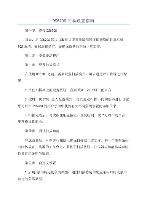
DS6708简易设置指南第一步:连接DS6708首先,将DS6708通过USB接口或其他适配器连接到您的计算机或POS系统。
确保连接稳定,并确保设备的电源正常工作。
第二步:安装驱动程序第三步:配置扫描模式在使用DS6708之前,需要配置扫描模式。
可以通过以下步骤进行配置:2.按住扫描器上的配置按钮,直到听到一次“叮”的声音。
3.此时,DS6708进入配置模式,可以通过扫描不同的条码进行设置。
您可以在DS6708的用户手册中找到有关不同条码设置的详细信息。
4.扫描完成后,再次按住配置按钮,直到听到一次“叮咚”的声音。
配置模式将退出。
第四步:测试扫描功能完成设置后,可以进行测试以确保扫描器正常工作。
将一个带有条码的物体放在扫描器的工作台上,并按下扫描按钮。
扫描器应该能够成功读取并显示条码的数据。
第五步:自定义设置1.启用/禁用特定的条码类型:通过扫描特定的配置条码启用或禁用特定的条码类型。
2.配置数据前后缀:可以添加前缀和后缀来自定义扫描的数据格式。
3.配置声音和振动提示:可以启用或禁用声音和振动提示来指示扫描操作的结果。
4.键盘模拟:可以将扫描数据模拟为键盘输入,以便在没有其他软件支持的情况下使用条码数据。
有关更详细的自定义设置信息,请查阅DS6708的用户手册。
第六步:维护和保养为了确保DS6708的正常运行,还需要进行定期的维护和保养。
以下是一些常见的维护任务:1.清洁:使用干净的软布和适当的清洁剂擦拭扫描仪的外壳和窗口。
定期清洁可以防止灰尘和污垢积聚,影响扫描质量。
2.定期检查连接:检查USB连接或其他连接是否稳定,确保线缆没有损坏或松动。
3.更新驱动程序:定期检查扫描器制造商的网站,以获取最新的驱动程序和固件更新。
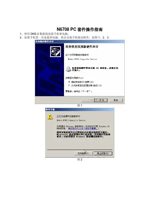
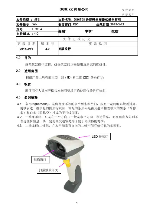
N6708 PC套件操作指南1、使用DKE-2数据线连接手机和电脑。
2、如果手机第一次连接到电脑,将会安装手机驱动软件。
如图1、2、3。
图1图2图3 3、安装后,出现图4,按下一步继续图4 4、给连接的手机命名,直到完成。
图5图6 5、设定同步设置图6 6、选择同步类型图77、“标准同步”设置,参见图8图8 8、“完全同步”设置,参见图9图99、在图7中,选择“联系人”同步,按“设定”。
默认的Outlook的同步路径为:contacts 如需更改,选择“建立文件夹(F)”。
如图10、11图10图1110、在图7中,选择“日历”同步,按“设定”。
如图12图1211、在图7中,选择“任务”同步,按“设定”。
如图13图1312、在图7中,选择“信息”同步,按“设定”。
如图14图1413、完成后,鼠标单击手机图标,如图15、16,选择“同步”,则可以开始同步数据了。
图15图1614、如果选择“同步站设定”,请参见步骤6-1315、选择“备份和恢复”,参见图17图17 1)单击“导入”按钮,设置导入的源数据,参见图18图182)单击“选项”按钮,可以设置备份的路径和其他功能。
图193)单击“备份”,则可以开始备份数据。
图2016、如果选择图16中的“信息”,会显示手机和电脑的连接模式和使用内存等信息。
图2117、如果选择图16中的“重命名”,可对手机重新命名。
图2218、如果选择图16中的“属性”,见图23图23。
DS-8000用户使用手册海康威视版v1.5目录1 产品介绍 (5)1.1 产品概述 (5)1.2 产品主要功能 (5)2安装说明 (8)2.1 清点设备及其附件 (8)2.2 装上硬盘 (8)2.3 后面板物理接口说明 (9)2.3.1 HC、HT、HF后面板说明 (9)2.3.2 1/2/3/4路HC及2路HT设备的后面板说明 (10) 2.3.3 HS、HTS设备的后面板说明 (11)2.4 报警线连接说明 (14)3 操作必读 (15)3.1前面板说明 (15)3.2 遥控器说明 (19)3.3 菜单项说明 (21)3.3.1 菜单导航 (21)3.3.2 菜单操作方法 (22)3.4 输入法说明 (23)4 基本操作指南 (24)4.1 开机 (24)4.2 预览 (24)4.3登录及修改用户名密码 (25) 4.4 云台控制 (27)4.5手动录像 (28)4.6 回放 (29)4.7 录像资料备份 (32)4.8 语音对讲 (34)4.9 辅口输出控制 (34)4.10 关机 (35)5参数设置操作指南 (36)5.1 管理员及其密码 (36)5.2 创建与删除用户 (37)5.3 修改设备名称与设备号 (40) 5.4 视频输出制式与VGA设置 (40) 5.5 OSD设置 (41)5.6 视频输入参数设置 (43)5.7 区域遮盖设置 (44)5.8 遮挡报警处理 (45)5.9 视频丢失处理 (46)5.10 移动侦测处理 (48)5.11本地预览属性设置 (51)5.12录像参数及录像计划表 (53) 5.13 报警输入输出设置 (57)5.14 网络参数 (60)5.15 解码器 (61)5.16 串口参数设置 (64)5.17 异常处理 (68)5.18 交易信息 (69)6 管理工具 (71)6.1保存设置 (71)6.2 恢复出厂设置 (72)6.3 升级 (72)6.4 硬盘管理 (72)6.5 清除报警 (72)6.6 重新启动 (72)6.7 关机 (73)6.8 日志 (73)6.8.1 按类型查询 (73)6.8.2按时间查询 (74)6.8.3按类型&时间查询 (74)6.9 查看系统信息 (74)7 网络硬盘录像机软件升级 (75)7.1配置FTP服务 (75)7.2 升级方式 (76)附录1、安装硬盘总容量的参考计算方法 (77)附录2 设备连接线的制作方法 (78)1 RS-485连接线制作方法 (78)2 UTP网络连接线制作方法 (78)3 RS-232连接线制作方法 (79)附录3 技术指标 (82)附录4 常用功能速查表 (83)附录5 常见故障解答 (85)1 产品介绍1.1 产品概述本设备是专为安防领域设计的一款优秀的数字监控产品。
摩托罗拉DS6708二维扫描枪
文章来源:扫描网
摩托罗拉DS6708二维扫描枪是一款什么样的扫描枪?有什么优势?下面扫描网把该款扫描枪的特征及优点整理出来供您参考,以便让您更好的选择。
摩托罗拉DS6708二维扫描枪的所有功能(例如全向1D/2D 条形码扫描)和嵌入式和基于服务器的解析代理组合到了一起。
摩托罗拉DS6708二维扫描枪可以全向扫描,很宽的工作范围,不必将商品与扫描器对齐,减少了培训时间和成本。
摩托罗拉DS6708二维扫描枪的特征及优点:
(1)嵌入式和基于服务器的分析代理:它使用户能够读取美国驱动程序的许可证上的PDF-417条形码并将该信息用于众多应用,包括自动填充信用卡或忠诚卡表单、年龄验证或退货监控表单
(2)很大的分辨率:1.3兆像素相机可处理图像、条形码和文档。
(3)组合功能:支持所有主要1D、PDF、邮政和2D码制。
(4)RSM(远程扫描仪管理):通过从中央位置实现远程管理降低IT 支出。
(5)设计坚固耐用:可承受多次跌落,将停机时间降至最短。
(6)钢化玻璃出射窗:增强了可视效果。
(7)多板载接口和通用电缆:确保了与未来技术的兼容性。
(8)全向扫描,很宽的工作范围:不必将商品与扫描仪对齐,减少了培训时间和成本。
(9)免提Intellistand(可选):实现投射扫描,可在免持与手持两种模式之间自动切换。
温馨提示:如果您想了解更多关于摩托罗拉DS6708二维扫描枪的信息,例如摩托罗拉DS6708二维扫描枪的产品参数等详细信息,可以上扫描网上了解。
如何调节条码扫描枪的声音大小?如何调节条码扫描枪的声音大小?条码扫描枪蜂鸣器的声音大小都是出厂默认的,可能有些客户会觉得声音太大或者太小,其实我们也可以设定声音大小。
条码扫描枪蜂鸣器的声音大小的设置可以在用户手册中找到。
但大多数条码扫描枪只有英文手册,所以对于英文较差的用户来说,可能就不怎么会设置了,扫描网小编特写此文,希望能帮助这些用户找到快速设置声音大小的方法。
由于条码扫描枪品牌和型号繁多,一下子也不能一一列出,所以下面以分别以扫描枪中英文手册为例,您也可以参考以下方法,在您的说明书中找到对应设置条码,扫描一下即可。
1 ) 以摩托罗拉条码扫描枪DS6708为例,摩托罗拉条码扫描枪手册都是英文的,我们首先在目录中找到关于蜂鸣器音量设置【Beeper Volume】的章节5-9,如下图。
点击一下目录中的【Beeper Volume】,将自动跳转到该页面,然后你就会看到调节音量大小的设置条码,分别为低音量、中音量和高音量三种选择。
您可以根据自己的需求来选择其中一种,然后扫描一下该条码即可。
2) 以民德MD2系列扫描枪为例,民德条码扫描前边个手册有中英文两个版本,我们在中文版手册目录中并没有看到蜂鸣器音量的相关文字,但是可以找到与蜂鸣器相关的章节【LED指示灯和其他】,我们找到这个页面就可以看到,里面有蜂鸣器音量大小的设置介绍,如下图:然后按照下面顺序依次扫描对应条码:a)扫描【开始设置】,b)扫描左边的【蜂鸣器音量】条码c)在手册最后一页,扫描你选择的音量右边对于的数字条码。
如“低音对应的是00,中音是01,高音是02*”d)扫描【结束设置】以上就是条码扫描枪声音大小调节的方法,其他品牌的条码扫描枪的声音大小设置步骤基本类似,您只需要在说明手册上找到蜂鸣器的设置章节,然后按照上面说的设置步骤依次扫描条码即可。
目录内容提要写作提纲正文一、资产减值准备的理论概述 (4)(一)固定资产减值准备的概念 (4)(二)固定资产减值准备的方法 (5)(三)计提资产减值准备的意义 (5)二、固定资产减值准备应用中存在的问题分析 (5)(一)固定资产减值准备的计提模式不固定 (5)(二)公允价值的获取 (6)(三)固定资产未来现金流量现值的计量 (7)(四)利用固定资产减值准备进行利润操纵 (8)三、解决固定资产减值准备应用中存在的问题的对策 (10)(一)确定积累时间统一计提模式 (10)(二)统一的度量标准 (11)(三)提高固定资产可收回金额确定方式的操作性 (11)(四)加强对固定资产减值准备计提的认识 (12)(五)完善会计监督体系 (12)参考文献 (15)内容提要在六大会计要素中,资产是最重要的会计要素之一,与资产相关的会计信息是财务报表使用者关注的重要信息。
DS-8000系列网络硬盘录像机用户基本操作指南1.菜单操作方法●按【主菜单/MENU】键,进入设备主菜单界面。
●按【放像/PLAY】快捷键,进入回放操作界面。
●按【录像/REC】快捷键,进入手动录像操作界面。
●按【云台控制/PTZ】快捷键,进入云台控制操作界面。
说明:进入时需输入密码,设备出厂时的用户名为“admin”,密码为“12345”。
如何退出菜单按【PERV】键可以退出菜单模式并切换到预览模式。
2.开机提醒:请确认接入的交流电压与硬盘录像机的要求相匹配,并保证硬盘录像机电源插座中间接地端接地良好。
在开机前请确保有一台监视器与后面板上的VOUT口相连接,或有一台显示器与后面板上的VGA口相连接,否则开机后将无法看到人机交互的任何提示,也无法操作菜单。
若【POWER】指示灯灭,请按以下步骤进行操作:第一步:若电源未插上,请插上电源,设备开始启动;这时设备若未启动,进入下一步;第二步:打开设备后面板的电源开关,设备开始启动。
若【POWER】指示灯呈红色,只要轻按【POWER】键,设备开始启动。
设备开始启动,【POWER】指示灯呈绿色注意:如果开机前,设备未安装硬盘,或安装的硬盘在开机初始阶段未被检测到,硬盘录像机将从蜂鸣器发出警告声音。
3.预览设备启动后即进入预览画面。
在预览画面上可以看到日期及时间、通道名称、每个通道的状态图标。
按数字键可以直接切换通道并进行单画面预览,10路机以下按一个数字键可切换到对应的通道,如按2就切换到第2通道;10路机或10路机以上必须按两个数字键才切换到对应的通道,如按02切换到第2通道,按12切换到第12通道。
按【编辑/EDIT】键可以进行手动轮巡。
自动轮巡的设置方法请参见5.11本地预览属性设置。
按【多画面/PREV】键可以对预览画面数量进行快速切换。
本地预览属性的设置本地预览属性的设置主要是在进行本地预览时,对预览模式、切换时间、是否需要音频预览及多画面显示时各窗口的通道顺序等属性进行定制。