Table of Contents
- 格式:pdf
- 大小:58.96 KB
- 文档页数:2

在RSC(英国皇家化学学会)的投稿要求中,Table of Contents(目录条目)指的是在论文中列出各章节和重要段落标题的列表。
它通常出现在论文的开头部分,以方便读者快速了解论文的内容和结构。
在撰写论文时,应该按照论文的逻辑结构和重要程度,将各个章节和重要段落的标题整理成一份简明扼要的列表,并按照适当的顺序进行排列。
每个标题前面可以加上相应的页码,以便读者快速找到感兴趣的内容。
在RSC的投稿要求中,Table of Contents需要遵循一定的格式和排版规范,例如字体、字号、行距、对齐方式等。
具体的格式要求可以参考RSC的投稿指南或联系编辑部获取详细信息。
总之,Table of Contents是论文中非常重要的一部分,它可以帮助读者快速了解论文的内容和结构,提高阅读的效率和体验。
因此,在撰写论文时应该认真编写Table of Contents,并遵循相应的规范和要求。
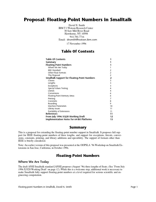
Proposal: Floating-Point Numbers in SmalltalkDavid N. SmithIBM T J Watson Research Center30 Saw Mill River RoadHawthorne, NY 10598914-784-7716Email: dnsmith@17 November 1996Table Of ContentsTable Of Contents1Summary1Floating-Point Numbers1Where We Are Today1IEEE Standard2Other Float Formats2This Proposal2Smalltalk Support for Floating-Point Numbers2Classes3Lengths3Exceptions3Special Values Testing4Literals4Conversions6Floating-Point Memory Areas6Printing7Constants8Rounding9Machine Parameters10Library Issues11Portability of Extensions11References11From July 1996 X3J20 Working Draft12Implementation Notes for 64-Bit Platforms13SummaryThis is a proposal for extending the floating-point number support in Smalltalk. It proposes full sup-port for IEEE floating-point numbers of three lengths, and support for exceptions, literals, conver-sions, constants, printing, and library additions and operability. The support of formats other thanIEEE is briefly considered.Note: An earlier version of this proposal was presented at the OOPSLA ’96 Workshop on Smalltalk Ex-tensions in San Jose, California, in October 1996.Floating-Point NumbersWhere We Are TodayThe draft ANSI Smalltalk standard [ANSI] proposes (August ’96) three lengths of floats. (See ’From July1996 X3J20 Working Draft’ on page 12.) While this is a welcome step, additional work is necessary tomake Smalltalk fully support floating-point numbers at a level required for serious scientific and en-gineering computation.Floating-point Numbers in Smalltalk, David N. Smith Page 1IEEE StandardThe IEEE floating-point standards are [IEEE85] and [IEEE87]. The 1987 standard and the 1985 standard define the same binary floating-point standard; the 1987 standard adds decimal floating-point for usein calculators. Both IEEE standards define four floating-point number sizes, as shown in Table 1: ’For-mats of IEEE Floating-Point Numbers’.The single and double widths are commonly implemented and supported. Double extended with 128bits is supported on some platforms.The 32-bit and 64-bit floating-point formats, from [IEEE85] are:The ’s’ field is the sign bit; the exponent field is a biased exponent, and the fraction field is the binaryfractional-part of the number less the leading 1-bit.Other Float FormatsVirtually all new hardware designs support IEEE floating-point number formats. The days of roll-your-own are gone. However, some older system designs still exist and do not use IEEE formats. These in-clude IBM S/390, for which a Smalltalk implementation exists. S/390 supports three widths, a 32-bitsingle width, a 64-bit double width, and a 128-bit extended (double-double) width. It is hexadecimalbased rather than binary.This ProposalThis proposal is intended to suggest areas in which Smalltalk needs additional support in order to pro-vide proper floating-point number support.Smalltalk Support for Floating-Point NumbersIEEE standard 754 and 854 arithmetic can be exploited in several ways in numerical software, providedthat proper access to the arithmetic’s features is available in the programming environment. Unfortu-nately, although most commercially significant floating point processors at least nearly conform to theIEEE standards, language standards and compilers generally provide poor support (exceptions includethe Standard Apple Numerics Environment (SANE), Apple’s PowerPC numerics environment, and Sun’sSPARCstation compilers).--- [Higham96] Page 492Smallt alk should support t hree lengt hs of float ing-point values, single, double, and an ext endedlength. It should completely support the IEEE standard, when IEEE format numbers are available, butnot exclude other formats where present.are shown in the four white data columns. Double-double is used by Apple on the PowerPC Mac-intosh [Apple96]; it consists of two double precision values taken together as a single 128 bit num-ber. Quad is an example of a 128 bit double extended format from one hardware implementation.s exponent fraction 182432-bit widths:1115264-bit widths:There are some problems with matching a language specification to hardware, and with compatibilitywith all existing Smalltalk systems. Since most existing Smalltalk systems don't do floats well, I've onlytried to provide some conversion path; that is, one might need to run a filter on the source of existingcode on some systems when imported into an ANSI Smalltalk system.ClassesFloating-point classes in this document are assumed to be the following:<realNumber>Float No instances, but has class methodsFloatSingleFloatDoubleFloatExtendedEach class should always be present. When a precision is not supported, the class should support thenearest precision. For example, on a plat form wit h no ext ended precision support, FloatExtended would be equivalent to FloatDouble, and on a platform with no single precision support, FloatSingle would be equivalent to FloatDouble. This allows development of code on one platform that can be runon another platform with different hardware.Class Float is suggested as a named superclass of the other classes in order to have a common class towhich inquiry messages are sent.Note that the current ANSI draft has a different class hierarchy.LengthsMachines which support only two lengths of floating-point number must make a choice as to whichshould be called which. If the IEEE floating-point standard is used, then the decisions are straight for-ward.FloatSingle would be single; it takes 4 bytes. FloatDouble would be double; it takes 8 bytes. FloatExtend-ed would be double extended, double-double, or quad, if any are present. If extended is missing, thenan implementation should substitute double, with or without a warning.On machines not implementing IEEE floating-point numbers, similar choices should be made usingthese guidelines:•Lengths which are similar to IEEE short should be short.•Lengths which are similar to IEEE double should be double.•Lengths which are significantly longer than double should be extended.Some fictitious machine might have two lengths of floats: 8 bytes and 16 bytes. Smalltalk should sup-port double and extended, forcing all single values to double.ExceptionsFloating-point arithmetic requires error detection support for overflow, underflow, and others. It mayalso require a way to test a result without raising an (expensive) exception. For example, one shouldbe able to write:xy := x div: y onUnderflow: 0.0d0.and/or:xy := x div: y onUnderflow: [ :result | 0.0d0 ].This should not generate any kind of underflow condition, but should simply answer 0.0d0 if an un-derflow occurs. The IEEE standard defines a number of conditions which may nor may not need toraise an exception depending on how they are computed. There are five exceptions; possible messagesfor performing operations and catching these exceptions is:Floating-point Numbers in Smalltalk, David N. Smith Page 3x operation: y onUnderflow: resultOrBlockx operation: y onOverflow: resultOrBlockx div: y onZeroDivide: resultOrBlockx operation: y onInvalid: resultOrBlockx operation: y onInexact: resultOrBlockThese correspond to what IEEE calls trap handlers. When a block is specified the result of the opera-tion is passed as a parameter. Note that not all operations can raise all exceptions.If no handler is specified, the default is to proceed with no exception. A set of five flags is maintainedwhich shows if one of the exceptions has occurred. It is reset only on request. Messages to test and setthese flags might be:Float exceptionStatus Answer a value holding all five flagsFloat exceptionStatus:Set the statusFloat clearExceptionStatus Clear all status flagsThe value answered by exceptionStatus is an integer with a value in the range 0 to 2r11111.Bit Mask Exception Message to answer the mask Message to answer the index 12r00001Invalid Float invalidExceptionMask Float invalidExceptionIndex 22r00010ZeroDivide Float zeroDivideExceptionMask Float zeroDivideExceptionIndex 32r00100Overflow Float overflowExceptionMask Float overflowExceptionIndex 42r01000Underflow Float underflowExceptionMask Float underflowExceptionIndex 52r10000Inexact Float inexactExceptionMask Float inexactExceptionIndex The actual bit values and masks may be implementation defined; their values are for illustration.On non-IEEE platforms, these status flags should be simulated when possible and feasible, but not theextent that performance is adversely affected.ExamplesPerform some action if a zero divide exception has occurred:(Float exceptionStatus bitAt: Float zeroDivideExceptionIndex) = 1 ifTrue: [ ... ].Clear the zero divide exception status bit:Float exceptionStatus: (Float exceptionStatus clearBit: Float zeroDivideExceptionMask )Special Values TestingSome IEEE result s include ’numbers’ which represent (signed) infinit y, not a number (NaN), andsigned zero. Tests to detect these are needed:x isNaNx isNotaNumberx isInfinitex isFinitex isNegativeInfinityx isPositiveInfinityx isZerox notZerox isPositiveZerox isNegativeZeroWhile some of these are simple comparisons with standardized values, others, in particular NaN, isnot. These should answer an appropriate value on hardware which does not support the test. (See also’Constants’ on page 8.)Some method of enquiring about the floating point support should be present. At least the followingshould be present:Float isIEEELiteralsSimple float literals have a period, but no exponent.1.2 3.14159272 12345.678901234567890Floating-point Numbers in Smalltalk, David N. Smith Page 5Short float literals have a period and an ’ e ’ indicating an exponent.1.2e0 3.14159272e0 1.2345678901234567890e4Note that last value may loose many digits of precision since it is forced to be short.Double float literals have a period and a ’d ’ indicating an exponent. 1.2d0 3.14159272d0 1.2345678901234567890d4Extended float literals have a period and an ’ x ’ (or ’ q ’ as in the draft standard) indicating an exponent. 1.2x0 3.14159272x0 1.2345678901234567890x4Simple floats are short, unless they contain enough digits that a longer size is needed to representthem. Thus:The value:12345.678901 is probably not equal to:12345.678901e0, but is probably equal to: 12345.678901d0.Since the value has more digits than a short float most likely has, it is made into a double.1 However, the size specified by the ' e ', ' d ', or ' x ' is always honored even if digits must be discarded. It is assumed that the programmer knows what she is doing in such cases, and such control over constantsis needed when writing certain kinds of library code. (I write more places than some platforms allowso that I'm assured of having enough places for the one with the largest size.)RadixRadix floats:16r1.2d15The value and exponent are hexadecimal 2r1.110110d1011 Both are in binaryRadix specification of floats is rarely needed but when it is needed, such as in building floating pointlibrary routines, it is critical to have it. Some existing systems allow radix floats, but have decimal ex-ponents. This proposal uses the same radix for exponents and uses the radix as the exponent base:fraction * (radix raisedToInteger: exponent)Thus:Base 2 and 16 can be used to specify the bits of constants precisely. This isFloatDouble pi : 16r3.243F6A8885A30d0For the implementer of basic algorithms, a way to specify the exact bits in an IEEE (or other) formatnumber should be available.16r400921FB54442D18 asIEEEFloatDouble "FloatDouble pi"IntegersExponents with no radix point should indicate integers, not floats:123e10 Should be: 1230000000000There is no good reason to make such numbers be floats, since it easy to add a radix point. On theother hand, there is no good way to write large and readable integer values unless exponents on inte-gers are allowed. (Note that some Smalltalk implementations support this today.)Literal Evaluated as Equivalent to2r1.0e12r1.0 * (2 raisedToInteger: 1) 2.016r1.0e116r1.0 * (16 raisedToInteger: 1)16.0ConversionsOther float lengthsOperations on floats of one length should produce results of the same length. Operations where thelength of one operand is longer than another should produce results of the length of the longer op-erand.Short-short:1.2e0 + 1.3e0produces:2.5e0Short-double:1.2e0 + 1.3d0produces:2.5d0Integers and DecimalsConversions from integer or decimal values to specified floating-point widths are:x asFloatSinglex asFloatDoublex asFloatExtendedCoercingNon-floating-point values should be coerced to the same length as the floating-point value whichforces the coercion. In this example, the integer 2 should be converted to a single precision value:1.0 + 2In cases where the other value will loose precision, such as in:1.0 + 1234567890123456789 " Produces a FloatSingle result"then the programmer should force a conversion to the appropriate floating-point precision:1.0 + 1234567890123456789 asFloatDouble " Produces a FloatDouble result "StringsConversions from string to numeric values should support all form of numeric literals and should fol-low the same rules as for compiling a literal with the same form. That is, given a numeric literal, itshould not matter whether it is compiled or converted from a string. The results should be equal.aString asNumber Convert a numeric literal in aString to a number; raise an ex-ception if aString does not contain a valid literal.aString asNumberIfError: aBlock Convert a numeric literal in aString to a number; if aString doesnot contain a valid literal, evaluate aBlock, passing the positionof the first character found to be invalid.Current Implementation. An implement at ion of asNumber can be found as readNumberString in [Smith95] pages 258-260. It converts floating point number literals to fractions, but only supports dec-imal radix.Floating-Point Memory AreasUsers of floating-point values frequently work with arrays of values. Implementing such arrays usingclass Array really provides an array of object pointers to floats stored elsewhere. This not only causesmemory usage to be much higher2, but imposes significant overhead in each floating-point number access. Further, such arrays cannot be readily passed to external routines, such as libraries written in FORTRAN.Smalltalk already has the concept of an object memory area, an area which holds many objects of a giv-en (primitive) class. Strings are a memory area for characters in which the ’raw’ value of a character is3stored in each element of the string, not an object pointer to a character.3.Thanks to Alan Knight for pointing this out with respect to floating-point values.In a similar fashion, Smalltalk needs to support floating-point memory. A new set of collection classesis needed.Object<somewhereAppropriate><floatingPointArray>FloatSingleArrayFloatDoubleArrayFloatExtendedArrayInstances of these classes need to have both the basic indexed collection protocol and an arithmeticprotocol, including both simple element-by-element operations as well as operations to support ma-trix computations. (Such operations need to be either inlined or done by a primitive on platforms thatcare about floating-point performance.) Operations on floating-point arrays need to be able to specifya target array:a plus:b into: cInstances should be stored in a way that is compatible with common scientific languages so that FOR-TRAN and/or C libraries can be called to directly operate on the values.MapsIn addition, there needs to be some way to map a floating-point array into a multi-dimensional ma-trix, possibly by simply specifying how indexing should be done. It should be easy to reference, with-out copying the values, a new floating-point array which represents some subpart, such as a columnor row.| fpa twoD row1 row2 row3 |fpa := FloatSingleArray new: 64.fpa atAllPut: 0.0.twoD := FloatMap on: fpa rows: 4.row1 := twoD at: 1." A reference to row 1; does not hold the data "row2 := twoD at: 2.row3 := twoD at: 3.row2 plus: row3 into: row1" Assigns all 16 values in row1 "The standard does not need to provide full matrix operations at this time, but does need to specify thelow level primitives from which more complex operations can be built.PrintingSupport for printing floating-point numbers is basically missing from most implementations; print-String usually produces something unacceptable: it has no ability to specify the width of the result,the precision of the result, or the format of the result. New floating point printing methods shouldallow a great degree of control over floating-point printing.There are two classes of methods proposed here: fixed width, used where the number of character po-sitions is known and specified, and variable width, used where the amount of precision required isknown and specified.Fixed Width PrintingFixed width printing prints values without an exponent whenever possible. In general, fixed widthprinting provides the most readable result with the maximum precision possible in the given width.aFloat printStringWidth: m Format aFloat into m characters.aFloat printStringWidth: m decimalPlaces: n Format aFloat into m characters, with n places to theright of the decimal point.Floating-point Numbers in Smalltalk, David N. Smith Page 7Variable Width PrintingaFloat printWithoutExponent Format to the full precision of the value and without an exponent; the result may be extremely long for verylarge or small exponents.0.0000000000012345678901234567aFloat printScientific Format with an exponent always present. 0.12345678901234567e-11aFloat printScientific: pSame, but precision limited to p decimal digits. 0.12345678e-11 for p=8.aFloat printEngineering Format with an exponent always present; the expo-nent is zero or a multiple of 3 or -3.12.345678901234567e-9aFloat printEngineering: pSame, but precision limited to p decimal digits. 12.345678e-9 for p=8.aFloat printMaximumPrecisionPrints the number to its full precision, so that the re-sulting string, if compiled, would produce a value equal to the receiver. (See [Burger96]). An exponent is present when required.aFloat printStringRadix: anInteger Format in radix anInteger with an exponent always present. Always provides the full precision of the val-ue. Radix 2 and 16 thus show the exact bits in the val-ue.416r1.DEALe0The standard printOn: method should answer the same value asprintMaximumPrecision .Current Implementation. An implemen t a tion of printScientific: (as printStringDigits:), printString-Width:, and printStringWidth:decimalPlaces: can be found in [Smith95] pages 260-273.ConstantsWhile it seems desirable to use a pool to hold floating point constants, there needs to be three differ-ent precisions, one for each floating-point class. It thus seems better to use class messages to fetch con-stant values.•FloatSingle pi •Float pi Not in the proposal; implementers can make it answer what it always did.•FloatDouble piOver180Answers: pi/180(Used internally in degressToRadians )•FloatDouble piUnder180Answers: 180/pi (Used internally in radiansToDegrees )•FloatExtended e •Special floating-point values, so that hand coded functions can answer the same kind of values ashardware operations, including:FloatDouble positiveInfinity FloatSingle negativeInfinity FloatExtended positiveZero FloatExtended negativeZero FloatSingle quietNaN FloatDouble signallingNaNFloatDouble signallingNaN: implementationDependentBitsresults of floating-point calculations which seem to answer unexpected results.Usage ExamplesMatching precisions. The correct precision of pi is selected to match the unknown precision of x: x * x class piNegative infinities. In some collection of floating-point numbers, negativeInfinity is used when finding the largest element. Note that it even could be said to work ’correctly’ when the collection is empty.maximumElement| max |max := self class negativeInfinity.self do: [ :element |element > max ifTrue: [ max := element ] ].^ maxUninitialized values. Initialize values in floating-point memory areas to signallingNan when they are created so that failure of a user to initialize elements can be detected.new: anInteger^ super newatAllPut: self class elementClass signallingNan;yourselfRoundingThe IEEE floating-point standard specifies four kinds of rounding:•Round to Nearest: This is the default; it produces the values nearest to the infinite-precision true result.Rounding of results can be directed to positive infinity, negative infinity, and zero.•Round to Positive Infinity: The value is equal to, or the next possible value greater than the infi-nite-precision true result.•Round to Negative Infinity: The value is equal to, or the next possible value less than the infinite-precision true result.•Round to Zero: For positive results, the value is equal to, or the next possible value less than the infinite-precision true result. For negative results, the value is equal to, or the next possible valuegreater than the infinite-precision true result.While most computations will use the default round-to-nearest mode, some computations use otherkinds of rounding. One example is interval arithmetic, in which two simultaneous calculations areperformed, one rounding to positive infinity and the other to negative infinity.Support for setting the rounding mode needs to be fast and simple, since it can be called frequently.One possibility is to add protocol to class Float:roundToNearest Set the rounding modesroundToPositiveInfinityroundToNegativeInfinityroundToZeroand:roundingMode Answer the current rounding moderoundingMode:Reset the rounding modeThe value answered by roundingMode is implementation dependent. Its values are defined by the ex-pressions:Float roundToNearestModeFloat roundToPositiveInfinityModeFloat roundToNegativeInfinityModeFloat roundToZeroModeFloating-point Numbers in Smalltalk, David N. Smith Page 9Convenience Methods. For convenience, class Float might provide protocol which saves the current rounding mode, sets a new mode, performs some operations, and restores the rounding mode: roundToNearest: aBlockroundToPositiveInfinity: aBlockroundToNegativeInfinity: aBlockroundToZero: aBlock}The basic operat ions, addit ion(+), subt ract ion (-), mult iplicat ion (*), and division (/) might have rounding versions (where the character • indicates one of the basic operations)a •b Round using the current rounding modea •~b Round to nearesta •>b Round to positive infinitya •<b Round to negative infinitya •=b Round to zeroFor example, (a *> b) would be functionally equivalent to:(Float roundToPositiveInfinity: [ a * b ])or:( [| mode result |mode := Float roundingMode.Float roundToPositiveInfinity.result := a * b.Float roundingMode: mode.result ] value )Example. This method is from a fictitious FloatDoubleInterval class:* anInterval| low high mode |mode := Float roundingMode.Float roundToNegativeInfinity.low := self lowest * anInterval lowest.Float roundToPositiveInfinityhigh := self highest * anInterval highest.Float rounding: mode.^ self class lowest: low highest: highMachine ParametersThere are a number of machine parameters which are suggested by various authors. See [Press92] and [Cody 88]. These include the floating point radix (2 for IEEE, 16 for S/390), number of digits in each width, largest and smallest floating-point numbers in each width, and others.These might be implemented as:FloatSingle digits On IEEE it produces: 24FloatDouble digits On IEEE it produces: 53Float base On IEEE it produces: 2FloatSingle base The sameFloatSingle maximumValue On IEEE it produces: 3.40e38FloatDouble maximumValue On IEEE it produces: 1.79e308FloatDouble guardDigitBits The number of bits of guard digits presentBut note these cases:Float digits An error; Float is abstractFloat maximumValue An error; Float is abstractSee [Press92] and [Cody 88] for more information and more parameters.Library IssuesISO 10967 Language Independent Arithmetic[ISO95] defines a number of library routines that should be supported in all languages. When the stan-dard is finished (it is now a draft) it will provide ’bindings’ for eight common languages (Ada, BASIC,C, Common Lisp, Fortran, Modula-2, Pascal, and PL/I), as the companion [ISO94] does for arithmetic operations.While Smalltalk is not defined by [ISO95], the recommendations of it should be followed as closely aspossible, at least in part since it is a significant attempt to standardize across languages.Most of the library is already a part of most Smalltalk implementations; while some functions aremissing, what is truly missing from Smalltalk is a precise definition of the functions, and a completeset of operations. (For example, the common arctan2 function is typically missing from Smalltalk im-plementations.)IEEE Library AdditionsThe Appendix to [IEEE87] lists a number of functions that languages should support on conforminghardware. These include copying the sign, next representable neighbor, test for infinite and NaN, andothers.Current Implementation. See [Cody93] for source for a C implementation.Portability of ExtensionsThe proposed ANSI Smalltalk standard indicates that subclasses and extensions to standard classes arenot portable.However, no provisions for numeric computation will ever be complete. Users will have extensionsand small vendors will market extensions. Since these extensions are quite necessary for the use ofSmallt alk in various scient ific, engineering, and financial areas, and since t he market s are alwayssmall, it is mandatory that the effort to port from one implementation to another not be extremelyhigh.The standard should specify that numeric classes be implemented in such a way as to assist such port-ability. The features that must be specified include:• A complete class hierarchy, with few if any abstract protocols.•Specification of coercion techniques and methods, including the ways in which certain kinds of numbers are determined to be more general than others.References[ANSI]American National Standards Institute draft Smalltalk Language Standard.[Apple96]’Chapter 2 - Floating-Point Data Formats’ in PowerPC Numerics, an HTML document: /dev/techsupport/insidemac/PPCNumerics/PPCNumerics-15.html#HEADING15-0[Burger96]Burger, Robert G, and R. Kent Dybvig. ’Printing Floating-Point Numbers Quickly andAccurately’ in Proceedings of the SIGPLAN ’96 Conference on Programming Language De-sign and Implementation. Also at:/hyplan/burger/FP-Printing-PLDI96.ps.gz[Cody88]Cody, W.J. ’Algorithm 665. MACHAR: A Subroutine to Dynamically Determine Ma-chine Parameters’, ACM Transactions on Mathematical Software, Vol. 14, No. 4, De-cember 1988, pp. 302-311. Software at:ftp:///netlib/toms/665.Z[Cody93]Cody, W.J. and J. T. Coonen. ’Algorithm 722: Functions to Support the IEEE Stan-dard for Binary Floating-Point Arithmetic’, ACM Transactions on Mathematical Soft-ware, Vol. 19 No. 4, pages 443-451, Dec 93. Software at:Floating-point Numbers in Smalltalk, David N. Smith Page 11。

table of contents 例子-回复读者提出的问题。
[table of contents 例子]文章标题:如何创建一个有效的目录示例引言:目录是一个有组织的结构,用于指导读者在长篇文章或书籍中找到特定部分的信息。
本文将详细介绍如何创建一个有效的目录,并提供一个例子来帮助读者更好地理解。
第一部分:目录的目的和重要性- 解释目录在文档中的作用,以及为什么有一个有效的目录对读者很重要。
- 强调一个好的目录可以帮助读者快速定位所需的信息,并提高阅读体验。
第二部分:创建目录的步骤1. 确定需要在目录中包含的内容:列出所有章节、子章节以及其他相关信息,以确定目录的结构。
2. 为每个章节和子章节创建标题:为每个章节和子章节添加一个有意义的标题,并确保标题之间有层次结构,以反映内容的组织。
3. 编写每个章节和子章节的页码:确定每个章节和子章节的起始页码,并将其添加到目录中。
4. 创建目录页面:在文档的开始处创建一个新页面,并在该页面上建立目录。
第三部分:目录示例下面是一个目录示例,展示了如何使用目录创建一个有效的阅读指南:目录1. 引言 (1)2. 第一部分:目录的目的和重要性 (2)2.1 目录在文档中的作用 (2)2.2 一个有效的目录为读者带来的好处 (3)3. 第二部分:创建目录的步骤 (5)3.1 确定需要包含的内容 (5)3.2 为每个章节和子章节创建标题 (6)3.3 编写页码 (7)3.4 创建目录页面 (8)4. 第三部分:目录示例 (10)结论:创建一个有效的目录可以帮助读者更轻松地浏览和导航长篇文档。
通过遵循本文提供的步骤,读者可以创建一个结构清晰、易于使用的目录。
使用目录来指导读者,能够使文档更加易于理解,提高阅读体验。

目录Table of Contents翻译的原则Principles of Translation中餐Chinese Food冷菜类Cold Dishes热菜类Hot Dishes猪肉Pork牛肉Beef羊肉Lamb禽蛋类Poultry and Eggs菇菌类Mushrooms鲍鱼类Ablone鱼翅类Shark’s Fins海鲜类Seafood蔬菜类Vegetables豆腐类Tofu燕窝类Bird’s Nest Soup羹汤煲类Soups主食、小吃Rice, Noodles and Local Snacks西餐Western Food头盘及沙拉Appetizers and Salads汤类Soups禽蛋类Poultry and Eggs牛肉类Beef猪肉类Pork羊肉类Lamb鱼和海鲜Fish and Seafood面、粉及配菜类Noodles, Pasta and Side Dishes面包类Bread and Pastries甜品及其他西点Cakes, Cookies and Other Desserts中国酒Chinese Alcoholic Drinks黄酒类Yellow Wine 白酒类Liquor 啤酒Beer葡萄酒Wine洋酒Imported Wines开胃酒Aperitif 白兰地Brandy威士忌Whisky金酒Gin朗姆酒Rum伏特加Vodka龙舌兰Tequila利口酒Liqueurs清酒Sake啤酒Beer鸡尾酒Cocktails and Mixed Drinks餐酒Table Wine饮料Non-Alcoholic Beverages矿泉水Mineral Water咖啡Coffee茶Tea茶饮料Tea Drinks果蔬汁Juice碳酸饮料Sodas混合饮料Mixed Drinks其他饮料Other Drinks冰品Ice•recipe 配方cookbook 菜谱ingredients 配料cook 烹调raw (adj.)生的cooked (adj.)熟的fried (adj.)油煎的fresh (adj.)新鲜的•cook 烹调bake 烘烤fry 油煎boil 煮沸broil 烤roast 烘烤simmer 炖,煨saute 煎炒•heat 加热cool 冷却freeze - froze 冻结melt 融化burn - burned / burnt 烧焦boil 煮沸•add 掺加include 包括remove 除去replace 代替mix 混合combine 结合stir 搅拌•spread 涂开sprinkle 撒slice切片 dice 切成块chop 剁,切细stuff 充填⏹烹饪方法英语:⏹shallow fry煎, shallow-fried 煎的, stir-fry 炒,deep fry 炸, toasted烤的(如面包),grilled 铁扒烤的,steam (蒸), stew/braise (炖,焖),boil(煮), roast/broil (烤), bake, smoke (熏), pickle (腌), barbecue (烧烤),翻译的原则一、以主料为主、配料为辅的翻译原则1、菜肴的主料和配料主料(名称/形状)+ with + 配料如:白灵菇扣鸭掌Mushrooms with Duck Webs2、菜肴的主料和配汁主料 + with/in + 汤汁(Sauce)如:冰梅凉瓜Bitter Melon in Plum Sauce二、以烹制方法为主、原料为辅的翻译原则1、菜肴的做法和主料做法(动词过去分词)+主料(名称/形状)如:火爆腰花Sautéed Pig Kidney2、菜肴的做法、主料和配料做法(动词过去分词)+主料(名称/形状)+ 配料如:地瓜烧肉Stewed Diced Pork and Sweet Potatoes3、菜肴的做法、主料和汤汁做法(动词过去分词)+主料(名称/形状)+ with/in +汤汁如:京酱肉丝Sautéed Shredded Pork in Sweet Bean Sauce三、以形状、口感为主、原料为辅的翻译原则1、菜肴形状或口感以及主配料形状/口感 + 主料如:玉兔馒头 Rabbit-Shaped Mantou脆皮鸡Crispy Chicken2、菜肴的做法、形状或口感、做法以及主配料做法(动词过去分词)+ 形状/口感 + 主料 + 配料如:小炒黑山羊Sautéed Sliced Lamb with Pepper and Parsley四、以人名、地名为主,原料为辅的翻译原则1、菜肴的创始人(发源地)和主料人名(地名)+ 主料如:麻婆豆腐Mapo Tofu (Sautéed Tofu in Hot and Spicy Sauce)广东点心Cantonese Dim Sum2、介绍菜肴的创始人(发源地)、主配料及做法做法(动词过去式)+ 主辅料+ + 人名/地名 + Style如:北京炒肝Stewed Liver, Beijing Style北京炸酱面Noodles with Soy Bean Paste, Beijing Style五、体现中国餐饮文化,使用汉语拼音命名或音译的翻译原则1、具有中国特色且被外国人接受的传统食品,本着推广汉语及中国餐饮文化的原则,使用汉语拼音。
BA Thesis 的基本格式或论文结构(现在基本上就是你们所说的Outline)Chapter/Part One Introduction★1.1 Literature Review (交代该部作品(电影)被读者/观众所接受的情况,特别是影评界对它的评价以及评价对自己的启发指导价值)Totem Dragon has been considered as the national symbol of China, while★1.2 Theoretical Framework and Methodology (就是介绍你要应用的理论,然后讲清楚它怎样被你所利用。
民族融合民族同化1.3 Thesis Statement and Research Questions (主题陈述以及你研究要回答的2或3个主要问题)。
(总之,你所做的准备都要写在第一章里,第二章就可以言规正传了)Chapter/Part Two。
(本章/节标题)2.1 (本节小标题)。
2.2(本节小标题)。
Chapter/Part Three 。
(本章/节标题)3.1(本节小标题)。
3.2(本节小标题)。
Chapter/Part Four 。
(本章/节标题)(主要内容)(如果需要,也可以设置章甚至更多主要内容)4.1 (本节小标题)。
4.2 (本节小标题)。
Chapter/Part Five Conclusion:(基于前面的研究之上得出,不要太短,否则,没有说服力)注:1。
带★的部分是你现在要面对的重点,因为你的论文是否具备可操作性,主要看这两部分。
2.你们的论文终稿将按此结构扩展而成,(除非必要)不必再加另外部分。
Table of contentPart 1 Basic knowledge of mechanicsUnit 1 General equilibrium conditions of systemReading Material 1 Static analysis of beamsUnit 2 Stress and StrainReading Material 2 Shear force and bending moment in beams.Unit 3 Normal stress and shear stressReading Material 3 Theories of strengthUnit 4 Membrane stresses in shell of revolutionReading Material 4 Stresses in cylindrical shells due to internal pressureUnit 5 Mechanical vibrationsReading Material 5 Static and dynamic balance of rotating bodiesPart 2 Metallic materialsUnit 6 MetalsReading Material 6 Stainless steelUnit 7 Properties of materialsReading Material 7 Standard mechanical testsUnit 8 Manufacturing engineering processesReading Material 8 Examples of manufacturingprocessesUnit 9 Internal structure of steelReading Material 9 Heat treatment of steelUnit 10 Corrosion of metalsReading Material 10 Corrosion controlPart 3 Process industryUnit 11 Chemical engineeringReading Material 11 Chemical industryUnit 12 Transport phenomena in process industry Reading Material 12 Principles of momentum transfer Unit 13 Principles of heat transferReading Material 13 Principle of mass transferUnit 14 Unit operation in chemical engineeringReading Material 14 EvaporationUnit 15 Chemical reaction engineeringReading Material 15 Chemical industry and environmental protectionPart 4 Process equipmentUnit 16 Pressure vessels and their componentsReading Material 16 Pressure vessel codesUnit 17 Design of pressure vesselReading Material 17 Stress categoriesUnit 18 Distilling equipmentReading Material 18 Packed towerUnit 19 Types of heat exchangersReading Material 19 Shell and tube heat exchanger Unit 20 Types of reactorsReading Material 20 Basic stirred tank designPart 5 Process machineryUnit 21 PumpsReading Material 21 The centrifugal pumpUnit 22 Pumping equipment for gasesReading Material 22 Reciprocating compressors and their applicationsUnit 23 Solid liquid separationReading Material 23 Centrifugal filtrationUnit 24 ValvesReading Material 24 Four types of valveUnit 25 Seal classificationReading Material 25 Primary sealing components Part 6 Process controlUnit 26 Introduction to process control 1Reading Material 26 Introduction to process control 2 Unit 27 General concept of process controlReading Material 27 Control categoriesUnit 28 Process control equipmentReading Material 28 Measuring devicesUnit 29 The modes of control action 1Reading Material 29 The modes of control action 2 Unit 30 Process control systemReading Material 30 Typical control systems。
Table of Contents(加粗,小二号,居中)
(中间空一行,使用段落中的空行标准)
Acknowledgements(加粗,四号) (i)
(此处空一行,使用段落中的空行标准)
Abstract (加粗,四号) (ii)
摘要(宋体,四号、加粗) (iii)
(此处空一行,使用段落中的空行标准)
Introduction(宋体,加粗,四号) (1)
I. Nature of Translation (加粗,四号,I. 点后空一格) (2)
1.1 Translation Is a Science (小四,不加粗,缩进) (2)
1.2 Translation Is an Art (同上) (4)
II. Prose Cognition (加粗,四号) (10)
2.1 What Is Prose?(小四,不加粗,缩进) (10)
2.2 What Are the Characteristics of Prose? (小四,不加粗) (10)
III. Aesthetics & Translation (11)
Conclusion(加粗,四号) (20)
Bibliography(加粗,四号) (21)
(此页英文字体Times New Roman,汉语宋体;页边距上、左2.5;下、右2.0;除Table of Contents为居中外其余行均为分散对齐;题号点后与题目之间空一格;次级题号与上一行词首对齐;此页不需页码)
段落中的空行标准操作方法:选中文本,点击菜单中的“段落”,选择“段前”空一行或“段后”空一行。
这样做出的空行大小适度,美观工整。
ITEAI nformation T echnology for E uropean A dvancement Task 1.3: Methodology Document for Addressing Resource Con-straints Problems in EmbeddedSystems (D1.3.1)Version 01 - PublicEdited by Yvan Barbaix & Stefan Van BaelenSoftware Development Process for Real-Time Embedded Software Systems(DESS)ITEA COMPETENCES involved:1) Complex Systems Engineering2)Communications3) Distributed Information and servicesOctober 2000Table of Contents1INTRODUCTION (2)2THE ROLE AND CHALLENGE OF TASK 1.3 (3)2.1R EAL-T IME C ONSTRAINTS (3)2.2M EMORY C ONSTRAINTS (4)2.3T HE C HALLENGE OF R ESOURCE D RIVEN C OMPONENT B ASED D ESIGN (5)3METHODOLOGY FOR RESOURCE CONSTRAINTS (7)3.1R EQUIREMENTS FOR S OFTWARE AND A RCHITECTURE E NGINEERING AND THE L IMITATIONS OF UML73.2R EVIEW OF N OTATIONS FOR T IMING C ONSTRAINTS (9)3.3E XTENSIONS OF UML FOR THE S PECIFICATION OF T EMPORAL C ONSTRAINTS (10)3.4I NTEGRATION OF T IMING AND S CHEDULABILITY A NALYSIS IN A UML D ESIGN F LOW (11)3.5D EVELOPMENT C OMPONENT S OFTWARE WITH P RECISE M EMORY R EQUIREMENTS (12)3.6C ONSIDERATION OF M EMORY C ONSTRAINTS IN A C OMPILER (13)4CONCLUSIONS (14)5REFERENCES (16)5.1E XTERNAL P UBLICATIONS FROM DESS P ARTNERS (16)5.2I NTERNAL D OCUMENTS (16)5.3E XTERNAL M ATERIAL (16)1 IntroductionThis document is the first internal deliverable of task 1.3 (timing, memory and other resource constraints). It is organised as follows.In section 2 the role and the challenge of this task in the scope of a component based design methodology are characterised. To meet these challenges all mem-bers conducted several individual studies on resource constraints. The individual studies have been synchronised on DESS workshops and meetings. The findings are documented as external publications or as internal reports. To clearly reflect each partners view and to provide a self-contained document, all these contributions are attached to this deliverable in the annex part. For a quick overview short summa-ries are given in section 3 as a reading guide.In concluding section 4 a first evaluation of task 1.3 is given. Part of this evaluation is the impact that these results have on other tasks of DESS. This evaluation has to be refined during the second part of the project leading to an updated version of this deliverable.2 The Role and Challenge of Task 1.3The main goal of task 1.3 is to provide methodological support to the designer of embedded systems on how to take into account resource limitations of the target environment. Task 1.3 is driven by partner’s needs:• application characteristics as documented in task 1.1• used tools and methods as documented in task 1.2On the other hand task 1.3 will have the following impact on the project:• guidance for the definition of components for embedded systems, especially integration of notations for constraints (WP 1.4)• methodological support to manage resource limitations during the design process (WP1.5 - WP1.8)Task 1.3 is clearly based on the results reported for task 1.1 in [4] and in [5]. Both documents contain an elaborated list of characteristics for embedded systems. It soon became apparent, however, that in this task we had to concentrate on the most important characteristics and these are surely timing and memory constraints. They are briefly presented in the following two sections.2.1 Real-Time ConstraintsIn [5] three different types of real time are distinguished in the usual manner:• hard real-time• soft real-time• statistical real-timeReal-time requirements can be quantified along the following list of metrics:• Period: As the controller behaves periodically, all necessary computations and adjustments of actuators must be completed within the given time interval. The period is e.g. imposed by a sensor device delivering its value periodically.• Deadline: The deadline of a task is measured relative to the beginning of the period. The task has to be guaranteed to have finished before this deadline. Note that the deadline is less than the period length, if there are several tasks that have to be completed within the given period.• Response Time: This is the longest time ever taken by a task from the beginning of its period until it completes its required computation, i.e. including all possible interferences by higher priority tasks and interrupt routines. The real-time con-straint is represented by the fact that the worst-case response time of a task has to be smaller than its deadline.• Release Time: An offset value that represents the arrival (release) of a certaintask with regard to the beginning of the period. The release time of a task must not be later than (deadline - WCET), where WCET is the Worst-Case Execution Time of the task.• Jitter: The amount of time the response time of a task can vary due to interfer-ences and inaccuracies caused to it and its predecessorsThe following figure illustrates these constraints1:2.2 Memory ConstraintsQuoting [5], section 1.1.3, "memory constraints come in two favours: constraints on the size and on the behaviour. Size constraints are particularly important in products for mass consumer markets. Indeed, if the memory of such products has to be increased, then this will have an immediate influence on the price of the appliance. Even for products where price is not an issue, the size is best determined in such a way that ample space is left for possible future extensions."And furthermore, "if there is a requirement for predictable, deterministic behaviour of the memory, then this constraint has an influence on the way the memory is used. (...) Deterministic behaviour usually disallows dynamic memory use, as well as time-unpredictable features such as virtual memory or cache."An additional requirement that is closely related to the size and cost of memory is the type of memory. Memory comes along as ROM/FLASH, RAM and EEPROM. As a matter of cost, usually the amount of ROM or FLASH on a microcontroller is much larger than RAM and especially EEPROM. Also, memory is typically organised in a non-linear way, with short and long address and the use of base addresses.Memory requirements can be quantified along the following list of metrics:• size• load• cost• dynamic behaviour1 Additional explanations can be found in the contribution "Constraint Specifications" by <partner 1> R&D in the annex part of this deliverable.• accounting for the data2.3 The Challenge of Resource Driven Component Based DesignA component based design methodology has very different facets, depending on the involved parties, their roles and expectations. This holds even for a rather focussed topic like "resource constraints".Right in the beginning of the project it became apparent that there are at least two different major views according to the following complementary terms:• design of components / design with components• component level view / system level view• notational view / analysis viewIn the former view the focus is on the single component. Here we are looking for means to describe the constraints which are attached to a component as a building block of a system.The later view is system centric. The focus is to analyse and validate system level constraints when designing such systems based on components.The relation between both view leads to the issues of composability and resource control in a component based development2. Consider a system under development. On the one hand there are constraints corresponding to the limited amount of available resources. On the other hand, there is a resource demand for supporting the system functions. The design problem can be seen as maintaining the demand lower than the constraint for any considered resource. Such a situation can be compared with the budget management in a complex building project, e.g. the target price (which is a constraint!) must be shared among all the project components .As soon as components are chosen, the expected price can be easily computed by simply adding the component prices. The predictability of the resulting price of the whole project relies only on the accuracy of the component price estimation.In a top down design, a system is decomposed into smaller active or passive agents. Any resource constraint to be respected must be partitioned among these agents. Hence, for a given resource, any agent will receive some "budget" corresponding to the amount of the given resource it is supposed to need.In a component based methodology such as to be DESS methodology, the designer selects among "of-the shelves" or "already developed and checked " components those who fit with the aforementioned agents. This component choice is driven by the function that the component supports but also by the amount of the given resource the component consumes which must be lower than its allocated budget 2 This very illustrative note on the composability issue has been provided by Jacques Pulou from <partner 1>.(which is again a constraint .. at the component level). Whatever the considered resource, components that fulfil some function which in turn need some amount of resource to be insured: this is the resource "demand" of the component. In a strictly top down design and for any resource, if the demand of each component is lower than its attributed budget then the methodology must warrant than the resulting system will not exhaust any of these resources.This crucial condition can be considered as well in a bottom up design process: given individual demand of each selected components, how can we compute the resource demand at the system level in order to verify whether it remains lower than the resource amount (the constraint) or not ?This mechanism aims to control, along the design process, the amount of resources that will be needed by the resulting system. This predictability of the designed system is of prime importance for DESS methodology. The key issue of such an approach lies in component "resource demand" definition which must fulfil the following crucial property: knowing the component demand, the demand of the whole system can be computed. This property is denoted as the "composability" of the component resource demands. Computing the system demand from the demand of each of its component is denoted as the composition of component resource demands.At this point, one can consider that predictability can be insured by an over estimat-ing composition operation in order to warrant the resource constraint. In that case, such a naïve approach cannot be followed because the price of predictability will be an unacceptable lack of efficiency.Example: Let us consider two processes than run asynchronously eachother but cooperate each other e.g. : exchanging each other some datawith respect to some synchronisation rules as producer/ consumer sche-mata. Memory demand of each process can be characterised either bytheir execution stack (if we restrict to stack memory resource) containsalong the process run or only by its maximal size. In this later case, sys-tem demand can be simply computed by adding these two maximal sizebut this can lead to drastically overestimating the required memory size. Atthe contrary If we choose the former case, the dynamic use of their stackmust be characterised and then composed taking into account the syn-chronisation between the two process execution.Thanks to these properties and because of the dynamic behaviour of the systems we want to design, "good" resource demand expressions are not easy to define. Most unfortunately, for sound resource demands, composition operation will not be limited to simple number addition like in the building project example!3 Methodology for Resource ConstraintsFollowing the descriptions in the previous sections it can be stated that the man-agement of resource constraints has a very broad scope. In order to achieve the goals of task 1.3 each partner involved performs individual studies on resource constraints. The proposals are documented as external publications or as internal reports. The results are synchronised on regular project meetings. Any findings are fed into other tasks mainly through personal involvement in these tasks.The work that has been performed in the first part of the project can be categorised as follows:Subject Partner<partner 4> • Requirements for software and architectureengineering and the limitations of UML• Review of notations for timing constraints <partner 1><partner 5> • Extensions of UML for the specification of temporalconstraints<partner 3> • Integration of timing and schedulability analysis in aUML design flow<partner 2> • Development component software with precisememory requirements• Consideration of memory constraints in a compiler <partner 1>The relations between these efforts can be graphically depicted as shown in Figure 1. The activities are summarised shortly in the following sections. The extended versions of these descriptions are appended in the annex of this document - in the same order as in the table above.3.1 Requirements for Software and Architecture Engineering and theLimitations of UMLAlthough UML (Unified Modelling Language) is a well defined and flexible modelling language its origins in the world of commercial computing show up in the lack of certain modelling requirements for real-time systems. For most (if not all) real-time systems, the issues of timeliness and schedulability are crucial. By definition real-time systems are concerned with time and ensuring that certain system activities can be carried out within defined timescales. The modelling techniques required to achieve these requirements involve performance modelling, which in turn, relies upon an ability to model the system architecture (as the actual components and their physical layout can have a significant effect on system performance) and the system concurrency (again the number and the characteristics of the concurrent tasks and the degree of task interaction between them can significantly affect system perform-ance).Figure 1: Relations between the activities in WP1.3Current normalised language UML 1.4 for the real-time development domain is insufficient for the expression of certain critical aspects, as the synchronisation and hardware/software interfaces.Sequence diagrams can be used to specify the detailed sequence of interaction not simply between actors and system, but between actors, interface devices and system software. It is also possible to annotate the diagram to show where non-functional requirements, in the form of timing constraints, apply. With sequence diagrams, it does not make it easy to distinguish between the different types of element involved with UML. It is not possible to compose a sequence diagram from more primitive sequence diagrams, furthermore it would be useful to have the possibility to annotate global time and synchronisation constraints on a group of treatments.There is no implicit UML notation to clearly represent tasks or any of the RTOS mechanisms that can be used to protect shared resources or facilitate inter-task communication. There is a need to address the problems of concurrency and timeliness issues in term of task definition and communication, mutual exclusion of shared resources, and in terms of timing details associated with objects communi-cation within and between tasks as well as the timing overheads associated with carried out by the RTOS.The UML deployment diagram allows to represent the different nodes and their connections of the system, a node contains packages and processes. The connec-tion types and nodes characteristics (processors configuration, memory card …) have an important impact on the architecture constraints of the target system. In UML the mapping between physical elements and other design elements is inade-quate. It is necessary for architecture modelling to cover software/hardware informa-tion and hardware characteristics such as speeds, memory capacities, bandwidth…The UML real time limitations are studied within the ATDPF (Analysis and design Platform Task Force) of the OMG (Object Management Group) at the origin of UML. However no standard is still finalised.By waiting for this normalisation, important actors on the UML tools market (also OMG member) propose UML tools more suitable for real-time development. How-ever these tools, as Rose-RT of Rational or Rhapsody of Ilogix for example, do not fit all the aforesaid needs. These tools allow automatic code generation for embed-ded targets by using principally notations of current UML1.4. So, such tools don't provide significative solutions to achieve performance and time requirements. The animation possibilities of behavioural diagrams (we can't really called such function-ality: simulation) allow an help for the debugging, but in any case don't have the ability to check or better to prove the respect of real time system requirements. These tools control representations detect today only two kinds of errors:• Pure syntax error• Using error due to bad notation or lack of coherence for a given component in the program.3.2 Review of Notations for Timing ConstraintsIn the literature various timing constraint expression styles can be found covering either the "scheduling theory framework" or deriving from the "real time programming language area". The review is organised on the classical distinction between time triggered (TT) systems and event driven systems but a special chapter is devoted to the rare attempts towards timing predictability of object oriented real time systems.In the framework of TT systems (chapter 2) general definitions are introduced and a clear distinction is made between "timed" criterion (to be minimised or maximised) and "timing" constraints that must be respected. At this point, we restrict ourselves to hard real time systems which discard any criterion and focus only on hard timing constraints. Then the more significant results in computing oriented scheduling theory are carefully described with a focus on the involved constraints. Pre-run time scheduling as well as run time scheduling approach are addressed and the most generally used algorithms are given with some insight on their advantages and drawbacks (e.g.: computational complexity for pre-run time scheduling and predict-ability for run time scheduling). Although rather old, this approach in its more sophisticated developments is still poorly tooled and, despite of their number, its results can hardly be straightforwardly applied to real life systems especially if they have not been built with predictability in mind.In the event driven system framework (chapter 3), we put the emphasis on the lack of methodology in this approach especially when priority run time scheduling is used. Concerning predictability, we enforce the need to take into account external envi-ronment behaviour in specifying timing constraints. To illustrate this fact, we briefly describe the approach followed at FT and show how external environment timing behaviour model is deeply involved in timing constraint specification.Throughout this contribution, timing constraints are described with the predictability issue in mind. We advocate that "schedulability" checking is of primary concern for the DESS methodology and that this topic is poorly covered by object oriented methods and tools. Consequently a summary of a first glance in this area is at-tempted in chapter 4.We conclude on three points:1. The limited number of timing constraints founded in the literature2. The difficulties to implement verified event driven real time system because ofthe gap between this kind of systems and "schedulability" results which address mainly time triggered systems3. The need of environment behaviour description if predictability of event drivendesign must be insured.Another result of this paper lies in the selected bibliography given in the last chapter (chapter 6): out of the enormous literature on these topics (especially scheduling), we propose a choice of reference books or papers that allow the reader to get further insight in this rather wide field.3.3 Extensions of UML for the Specification of Temporal ConstraintsFormal methods3 have been proposed and successfully employed in the develop-ment of real-time (RT) software systems where features like safety needed to be formally proved. However, formal notations are generally considered too difficult or too expensive to be used in "ordinary" RT software development. On the contrary, UML is becoming extremely popular, essentially because it is a semi-formal notation relatively easy to use (being mostly a graphical notation), and because it is provided with tools that support (although to a limited extend) code generation. However, UML was not conceived for modelling RT software: its application of UML in the real-time domain is limited for lack of constructs to express time-related constraints and properties, as well as by the lack of formal semantics.We are going to explain some techniques that permit to specify RT systems with the 3 The description in this section is an expert from the documents "Specification of GRC Problem using UML" and "Specification of ACL 8000" by Gabriele Quaroni and Matteo Venturelli. These two documents are internal studies from <PARTNER 5>. The former GRC problem is a widely used benchmark problem for the specification of safety critical systems. The later refers to a real product from <PARTNER 5>.UML notation. At the same time we will propose some extension to UML. The solution we have designed is based on the following UML "schema":• Class diagrams are used to provide the static structure of the system. Classes and their attributes identify elements and values that are considered to be essen-tial in the behavioural definition.• State diagrams describe the dynamic behaviour of the system and tell how the system has to be developed - correct and complete.• The OCL syntax is used to express relations between values important to the system as well as properties a system has to respect during its evolutions. This instrument is as powerful as difficult to use. Therefore, we try to use it as few as possible.In the sequel we will focus our attention time-out constraints as a special type of temporal constraints. UML does not provide any instruments that allow us to express that a transition, leaving a state, has to trigger within x time units after the activation of that state. In order to express such constraints we introduced the "Anomaly" state in which the system goes only if the normal transitions don’t perform in time. The trigger of the transition ending in the error state is "After(x)" which is an official UML phrase. Note that the "Anomaly" state here just indicates that the behaviour of the system deviated from the specifications. In an implementation, we would wish to substitute it with an exception handling mechanism, for the sake of robustness.Another problem with standard UML is that it does not deal with simultaneous events. We discover the necessity to describe the correct priority in handling events. In order to express this constraint we used the UML guard syntax, forcing their semantics to express the check of the occurrence of an event at a given moment.I.e. the triggering of the time-out transition is conditioned to the non-occurrence of the completion event of the critical job.A third problem has been encountered when we tried to explicitly refer to the time when an event occurs. UML provides some keywords to denote this. However, different transitions can be annotated by such an event and which transition triggers is dependant on the active state. The labelling mechanism of UML can be used in sequence diagrams and collaboration diagrams to identify individual transition instances. It is possible to use it in state diagrams too.3.4 Integration of Timing and Schedulability Analysis in a UML Design Flow The position paper in [3] was presented at the workshop on "Formal Design Tech-niques for Real-Time UML" during UML’20004. The assumption behind this contribu-tion is that a component based design for embedded systems can be based on UML, especially with those extensions of UML such as UML-RT, that already support certain features of embedded systems.Nevertheless, there are still a number of open issues to be solved for this approach.4 An extended version of this position paper is currently being written.We have identified two such areas which we address in our contribution. The first area is a potential inconsistency between different languages of the UML (e.g. sequence diagrams and statecharts). The second area is the missing support for late design phases, especially w.r.t. to the analysis of temporal constraints. Therefore, we are proposing to define a suitable consistency notion for the seman-tics of models and for timing constraints. Having such a notion for behavioural aspects and resource restrictions it would be possible to establish bridges to late design phases, especially code generation, timing analysis, and schedulability tests for distributed embedded systems. A sample application is to check whether the code generated for the behavioural statechart of a component fulfils the timing requirements expressed in different sequence diagrams and whether all these objects can be scheduled in such a way that the restrictions of all diagrams can be met.Although many of the techniques we mention are well established on their own, their integration in a UML based design approach is still challenging.3.5 Development Component Software with Precise Memory RequirementsIn a position paper [1], presented at ECOOP 2000, we described one possible way to develop component software with precise memory requirements. The goal of the paper is to describe one way to use component based development (CBD) for memory aspects as typically required by embedded systems developers.The presented mechanism used to develop a CBD application requires strong links with the compiler/linker environment as well as the development tool (case tool). While developing a component, the compiler is able to deduce the exact memory requirements of the component based on the target code (see the following section on the consideration of memory constraints in a compiler). This amount consists of a fixed part and a variable part depending on the calling environment. This information is fed back to the component’s source-level. Later, while designing an application that uses that component, the tool will extract the memory information and use it to compute the application’s total memory requirement.Note that as the exact memory usage of a component depends on its calling environment (the way a component is used), it is possible to get a component usage that would require unlimited amounts of memory. When this occurs, the com-piler/linker mechanism will require the user to add memory parameter knobs to the source to artificially limit the memory usage, i.e. meta-level constructs that limit the upper bound of the memory (optionally checked during runtime). At component-plug-time, the application-builder should set some knobs to case specific values and should link related knobs to each other so that turning one memory knob moves the related memory knobs simultaneously.This CBD approach for memory requirements has several drawbacks though. First, as there is a strong link between the source code, the target code and the develop-ment tool, the implementation of such a development environment would require a。
table of contents 例子Table of Contents Example:Chapter 1: Introduction1.1 Background1.2 Purpose of the Study1.3 Research Questions1.4 Significance of the StudyChapter 2: Literature Review2.1 Theoretical Framework2.2 Previous Studies2.3 Gaps in the Literature2.4 Conceptual FrameworkChapter 3: Methodology3.1 Research Design3.2 Data Collection Methods3.3 Sampling Technique3.4 Data AnalysisChapter 4: Results4.1 Presentation of Findings4.2 Analysis of Results4.3 Discussion of FindingsChapter 5: Conclusion5.1 Summary of the Study5.2 Implications of the Study5.3 Limitations and Recommendations for Future Research ReferencesAppendices附录A: 调查问卷附录B: 原始数据以上是一个使用中文的目录示例,共包含五个章节,每个章节下分为几个小节进行细分。
章节1介绍研究的背景、目的、研究问题和研究的重要性。
章节2进行文献综述,包括理论框架、先前研究、文献的不足之处以及概念框架。
章节3详细描述了研究的方法论,包括研究设计、数据收集方法、抽样技术和数据分析。
章节4呈现了研究结果,并进行了结果分析和讨论。
Machinery's Handbook 27th Edition
TABLE OF CONTENTS
COPYRIGHT iv PREFACE v ACKNOWLEDGMENTS ix MATHEMATICS 1• NUMBERS, FRACTIONS, AND DECIMALS • ALGEBRA AND
EQUATIONS • GEOMETRY • SOLUTION OF TRIANGLES
• LOGARITHMS • MATRICES • ENGINEERING ECONOMICS MECHANICS AND STRENGTH OF MATERIALS 138• MECHANICS • VELOCITY, ACCELERATION, WORK, AND ENERGY
• FLYWHEELS • STRENGTH OF MATERIALS • PROPERTIES OF
BODIES • BEAMS • COLUMNS • PLATES, SHELLS, AND
CYLINDERS • SHAFTS • SPRINGS • DISC SPRINGS • WIRE ROPE,
CHAIN,
ROPE, AND HOOKS
PROPERTIES, TREATMENT, AND TESTING OF MATERIALS 396• THE ELEMENTS, HEAT, MASS, AND WEIGHT • PROPERTIES OF
WOOD, CERAMICS, PLASTICS, METALS, WATER, AND AIR
• STANDARD STEELS • TOOL STEELS • HARDENING, TEMPERING,
AND ANNEALING • NONFERROUS ALLOYS • PLASTICS DIMENSIONING, GAGING, AND MEASURING 629• DRAFTING PRACTICES • ALLOWANCES AND TOLERANCES FOR
FITS • MEASURING INSTRUMENTS AND INSPECTION METHODS
• SURFACE TEXTURE
TOOLING AND TOOLMAKING 746• CUTTING TOOLS • CEMENTED CARBIDES • FORMING TOOLS
• MILLING CUTTERS • REAMERS • TWIST DRILLS AND
COUNTERBORES • TAPS AND THREADING DIES • STANDARD
TAPERS • ARBORS, CHUCKS, AND SPINDLES • BROACHES AND
BROACHING • FILES AND BURS • TOOL WEAR AND SHARPENING
• JIGS AND FIXTURES
MACHINING OPERATIONS 1005• CUTTING SPEEDS AND FEEDS • SPEED AND FEED TABLES
• ESTIMATING SPEEDS AND MACHINING POWER • MACHINING
ECONOMETRICS • SCREW MACHINE FEEDS AND SPEEDS
• CUTTING FLUIDS • MACHINING NONFERROUS METALS AND NON-
METALLIC MATERIALS • GRINDING FEEDS AND SPEEDS
• GRINDING AND OTHER ABRASIVE PROCESSES • KNURLS AND
KNURLING • MACHINE TOOL ACCURACY • NUMERICAL
CONTROL • NUMERICAL CONTROL PROGRAMMING • CAD/CAM MANUFACTURING PROCESSES 1326• PUNCHES, DIES, AND PRESS WORK • ELECTRICAL DISCHARGE
MACHINING • IRON AND STEEL CASTINGS • SOLDERING AND
BRAZING • WELDING • LASERS • FINISHING OPERATIONS
Each section has a detailed Table of Contents or Index located on the page indicated
TABLE OF CONTENTS
FASTENERS 1473• NAILS, SPIKES, AND WOOD SCREWS • RIVETS AND RIVETED
JOINTS • TORQUE AND TENSION IN FASTENERS • INCH
THREADED FASTENERS • METRIC THREADED FASTENERS
• BRITISH FASTENERS • MACHINE SCREWS AND NUTS • CAP AND
SET SCREWS • SELF-THREADING SCREWS • T-SLOTS, BOLTS, AND NUTS • PINS AND STUDS • RETAINING RINGS • WING NUTS, WING SCREWS, AND THUMB SCREWS
THREADS AND THREADING 1721• SCREW THREAD SYSTEMS • UNIFIED SCREW THREADS
• METRIC SCREW THREADS • ACME SCREW THREADS • BUTTRESS THREADS • WHITWORTH THREADS • PIPE AND HOSE THREADS
• OTHER THREADS • MEASURING SCREW THREADS • TAPPING
AND THREAD CUTTING • THREAD ROLLING • THREAD
GRINDING • THREAD MILLING • SIMPLE, COMPOUND,
DIFFERENTIAL, AND BLOCK INDEXING
GEARS, SPLINES, AND CAMS 2026• GEARS AND GEARING • HYPOID AND BEVEL GEARING • WORM
GEARING • HELICAL GEARING • OTHER GEAR TYPES • CHECKING
GEAR SIZES • GEAR MATERIALS • SPLINES AND SERRATIONS
• CAMS AND CAM DESIGN
MACHINE ELEMENTS 2214• PLAIN BEARINGS • BALL, ROLLER, AND NEEDLE BEARINGS
• STANDARD METAL BALLS • LUBRICANTS AND LUBRICATION
• COUPLINGS AND CLUTCHES • FRICTION BRAKES • KEYS AND
KEYSEATS • FLEXIBLE BELTS AND SHEAVES • TRANSMISSION
CHAINS • STANDARDS FOR ELECTRIC MOTORS • ADHESIVES
AND SEALANTS • MOTION CONTROL • O-RINGS • ROLLED STEEL
SECTIONS, WIRE, AND SHEET-METAL GAGES • PIPE AND PIPE
FITTINGS
MEASURING UNITS 2539• SYMBOLS AND ABBREVIATIONS • MEASURING UNITS • U.S.
SYSTEM AND METRIC SYSTEM CONVERSIONS
INDEX 2588 INDEX OF STANDARDS 2677 INDEX OF INTERACTIVE EQUATIONS 2689 INDEX OF MATERIALS 2694 ADDITIONAL INFORMATION FROM THE CD 2741• MATHEMATICS • CEMENT, CONCRETE, LUTES, ADHESIVES, AND SEALANTS • SURFACE TREATMENTS FOR METALS
• MANUFACTURING • SYMBOLS FOR DRAFTING • FORGE SHOP
EQUIPMENT • SILENT OR INVERTED TOOTH CHAIN • GEARS
AND GEARING • MISCELLANEOUS TOPICS
Each section has a detailed Table of Contents or Index located on the page indicated。