用户操作手册[优质文档]
- 格式:doc
- 大小:3.82 MB
- 文档页数:33
广州建筑企业诚信排名评价体系用户操作手册简介广州建筑企业诚信排名评价体系是由广州市建设项目质量安全监督站开发的一款企业信用评估工具。
该工具旨在通过对建筑企业信用记录的整理、评定和排名,为广大客户提供更优质的服务和建设方案,促进广州建筑市场的健康有序发展。
登陆操作在打开广州建筑企业诚信排名评价体系的主页面后,用户首先需要进行登陆操作:1.点击主页面左上角的“登录”按钮。
2.在跳转的登录页面中,输入用户名和密码。
3.点击“登录”按钮即可成功登陆。
如果您忘记了密码,可以点击登录页面下方的“找回密码”链接,按照页面提示进行密码找回操作。
查询操作登陆成功后,用户可以在网站的“查询”页面中进行查询操作。
具体流程如下:1.点击主页面右上角的“查询”按钮。
2.在跳转的查询页面中,按照需求选择查询条件(例如企业名称、企业信用代码等)。
3.点击“查询”按钮即可查询到对应的企业信用记录。
需要注意的是,查询结果将根据企业的信用记录,依据广州建筑企业诚信排名评价体系的评估标准进行排名。
统计报表广州建筑企业诚信排名评价体系还提供了一系列统计报表,用户可以在网站的“统计报表”页面中进行查看。
具体流程如下:1.点击主页面右上角的“统计报表”按钮。
2.在跳转的统计报表页面中,按照需求选择统计报表类型(例如全市企业信用排名、某一时期内信用评估情况等)。
3.点击“生成报表”按钮即可生成对应的统计报表。
需要注意的是,统计报表将根据广州建筑企业诚信排名评价体系的评估标准进行生成。
用户可以根据需要进行导出、打印等操作。
评价标准广州建筑企业诚信排名评价体系的评价标准主要包括以下几个方面:•企业基本信息:包括企业名称、企业信用代码、法人代表等信息。
•企业信用记录:包括企业对外宣传、企业在公共领域的表现等信息。
•企业管理水平:包括企业质量管理、安全生产管理等信息。
•企业经济实力:包括企业经济规模、经济效益等信息。
对于以上评价标准,广州市建设项目质量安全监督站将根据相应的指标进行评价,最终生成企业信用记录和排名结果。

附件2:中国华电集团公司招标与采购网电厂用户操作手册<版本号:4.1>中国华电集团公司招标与采购网2011年03月05日目录目录.......................................... 错误!未指定书签。
1前言 ......................................... 错误!未指定书签。
1.1网站概述...................................... 错误!未指定书签。
1.2网站建设指导思想和运营理念.................... 错误!未指定书签。
1.3网站主要功能.................................. 错误!未指定书签。
1.4网站使用前的说明.............................. 错误!未指定书签。
2用户管理操作说明.............................. 错误!未指定书签。
2.1会员管理操作说明.............................. 错误!未指定书签。
2.2系统管理员登录................................ 错误!未指定书签。
2.3采购个性设置.................................. 错误!未指定书签。
2.4开票单位设置.................................. 错误!未指定书签。
2.5部门管理...................................... 错误!未指定书签。
2.6用户管理...................................... 错误!未指定书签。
3后台业务系统总体说明.......................... 错误!未指定书签。
3.1系统功能区域介绍.............................. 错误!未指定书签。

coat master Flex用户操作手册coat master Flex© 2019-2021 coatmaster AG未经coatmaster AG 明确许可,不得分发和复制本文档,也不得出于合法目的使用和传播本文档内容。
有关违规将受到法律诉讼。
如果是授予专利或实用新型注册(ISO-16016),则保留所有权利。
由于技术变化和印刷错误,本文档所给出的数值都是近似值,不应作为法律担保的依据。
这些数值可能会根据元件的误差而发生变化。
上次更新:05/2021coat master Flex1目录1目录 (2)1技术资料 (4)2客户要求和设备规范 (5)3应用 (6)4功能和测量原理 (6)5安全和责任 (7)5.1警告符号 (7)5.2标志与 Figure 示 (8)5.2使用不当 (9)5.3产品安全 (10)6交货范围 (11)7设置 (12)7.1电池 (13)7.1.2电池安装 (13)7.2导览面板 (14)7.3打开/关闭电源 (14)7.4语言选择 (14)7.5Wi-Fi 设置 (16)7.6启动 (17)7.7使用coatmaster®Flex 操作本地伺服器 (18)8操作说明 (19)8.1系统设定 (19)8.2主功能表 (22)8.3分组菜单 (23)8.4应用功能表 (24)8.5测量 (33)8.6资料传输/云端 (34)8.6.1登录 (34)8.6.2应用 (36)8.6.3监控 (36)9故障排除和最佳解决方案 (39)9.1错误讯息 (39)9.2错误代码 (39)9.3常见问题 (42)9.4咨询热线 (42)10储存和运输 (42)11维护和维修 (43)11.1更换过滤棉 (44)11.2清洁和护理 (44)11.3保修期 (44)12. API 接口描述 (45)前言亲爱的客户,感谢购买并使用coatmaster®Flex,它能高效协助优化工艺及生产优质产品。


RJS用户手册版本号:V1.0使用产品前请仔细阅读本手册版权说明本手册的版权为深圳市泰科智能伺服技术有限公司所有。
未经泰科智能许可,不得以任何方式复制和抄袭本手册的内容。
本文档仅供用户参考,文档中的内容力图精确和可靠,但错误和疏忽之处在所难免,如果您发现错误,请不吝赐教。
泰科智能保留随时修改和完善本文档的权利,有疑问请咨询我们,谢谢。
安装、使用产品前,请阅读本手册。
本手册主要包含以下信息:关节简介关节型号说明关节性能参数电源电压和电流关节配置和安装关节驱动器软件调试制动器功能关节尺寸更多信息如您还需要了解RJS关节模组的更多信息,请登录网站:目录版权说明 (2)前言 (5)1. 安全信息 (6)1.1警告 (7)1.2注意事项 (8)2. 产品质保 (10)2.1产品质量保证 (10)2.2免责声明 (10)3. 产品简介 (11)3.1概述 (11)3.2型号说明 (13)3.3关节参数 (14)3.4电源电压和电流 (17)4. 关节配置和安装 (18)4.1 关节配置 (18)4.2关节电源和通讯线 (19)4.3关节安装 (20)4.4关节旋转限制 (23)4.5 CANopen 终端 (23)5. 关节驱动器 (24)5.1驱动器概述 (24)5.2驱动器接口 (25)6. 软件调试 (27)7. 制动器功能和手动释放制动器 (28)7.1制动器功能 (28)7.2手动释放制动器 (28)8. 关节常见问题及处理 (30)9. 关节尺寸图 (31)前言感谢您购买和使用本公司RJS系列机器人关节模组,我们将为您提供优质的产品服务RJS系列关节模组是本公司推出的一款基于模块化理念设计、轻巧、高精度的协作机器人关节;一体化集成的RJS不仅结构紧凑、安装简便、高性价比,节约您在协作机器人的设计、组装等多个环节投入的成本,同时我们不断的对产品进行升级、优化和定制化服务,提供更丰富的产品选择,方便您更加自由灵活的设计自己的机器人。
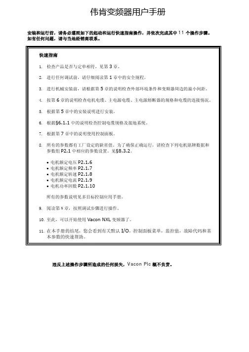
伟肯变频器用户手册安装和运行前,请务必遵照如下的起动和运行快速指南操作,并依次完成其中11个操作步骤。
如有任何问题,请与当地经销商联系。
快速指南1. 检查产品是否与定单相符,见第3章。
2. 进行任何调试前,请仔细阅读第1章中的安全规程。
3. 进行机械安装前,请根据第5章的说明检查外部环境条件和变频器周边的最小间距。
4. 按第6章的说明检查电机电缆、主电源电缆、主电源熔断器的规格和电缆的连接情况。
5. 根据第5章中的安装说明进行安装。
6. 根据§6.1.1中的说明检查控制电缆规格及接地系统。
7. 根据第7章中的说明使用控制面板。
8. 所有的参数都有工厂设定的缺省值。
为了确保正确运行,请检查下列电机铭牌数据和参数组P2.1中相应的参数设置。
见§8.3.2。
• 电机额定电压P2.1.6• 电机额定频率P2.1.7• 电机额定转速P2.1.8• 电机额定电流P2.1.9• 电机功率因数P2.1.10所有的参数说明见多目标控制应用手册。
9. 阅读第8章,按照调试步骤进行操作。
10. 至此,可以开始使用Vacon NXL变频器了。
11. 在本手册的结尾,您会看到有关默认I/O,控制面板菜单,监控值,故障代码和基本参数的快速帮助。
违反上述操作步骤所造成的任何损失,Vacon Plc概不负责。
目录VACON NXL用户手册目录1 安全指导2 EU认证3 收货4 技术数据5 安装6 电缆和接线7 控制面板8 调试9 故障跟踪10 选件卡OPT-AA的描述11 选件卡OPT-AI的描述VACON NXL多目标控制应用手册vacon • 3Vacon China电话: +86-10-51280006 传真: +86-10-65813733 24小时支持热线: +86-137******** Email :***************.cn关于VACON NXL 用户手册和多目标控制应用手册恭喜您选择了Vacon NXL 变频器所提供的平滑控制!用户手册将为您提供有关Vacon NXL 变频器的安装,调试和操作的必要信息。
客户服务中心操作手册客户服务中心操作手册一、前言本操作手册旨在为客服中心的客服代表提供基本的操作指南和技能,以便他们能更好地服务客户,解决问题,并提升客户满意度。
此手册并不是详尽无遗的,因此,客服代表应接受持续的训练和学习,以便适应不断变化的业务需求和客户期望。
二、客服中心的主要功能客户服务中心的主要功能包括:1、接受并处理来自客户的咨询和请求。
2、根据客户需求提供解决方案和建议。
3、确保客户问题得到及时、准确和有效的解决。
4、通过提供优质服务,提高客户满意度。
三、操作流程以下是一些基本的操作流程:1、接收客户咨询:客服代表应始终保持友好和专业的态度,礼貌地询问客户问题,并充分理解客户需求。
2、查询和解决问题:根据客户需求,客服代表应查询相关资料,并尽快提供解决方案。
如果问题较为复杂,应请示高级客服代表或主管。
3、记录和跟踪:客服代表应详细记录客户问题和解决方案,确保可以随时查阅。
如有必要,应进行后续跟踪以确认问题是否得到解决。
4、反馈和改进:定期收集客户反馈,分析问题出现的原因,并采取措施改进服务质量。
四、技能要求客服代表应具备以下技能:1、良好的沟通技巧:能够清晰、准确地表达自己的观点,理解客户需求,并保持良好的情绪沟通。
2、强大的问题解决能力:能够快速分析问题,找到合适的解决方案,并有效地实施。
3、团队合作能力:能够与同事有效协作,共同解决问题,提高整体服务质量。
4、持续学习的态度:愿意接受新的知识和技能,不断提升自己的专业能力。
五、培训和发展为了提高客服代表的服务质量和技能,应定期进行培训和发展活动,包括:1、新员工培训:为新加入的客服代表提供基础知识和技能培训,以确保他们能快速适应工作。
2、在职培训:定期提供在职培训,包括新的服务技巧、沟通和问题解决策略等,以提升现有员工的专业能力。
3、交叉培训:让员工了解并掌握不同的职位技能,增强团队的灵活性和适应性。
4、绩效评估和奖励:定期评估员工的工作表现,对优秀员工给予奖励,以激励员工持续提升自己的服务质量。

C1User Manual DesktopConsoleCopyright © 2018 Xi ’an NovaStar Tech Co., Ltd. All Rights Reserved.No part of this document may be copied, reproduced, extracted or transmitted in any form or by any means without the prior written consent of Xi ’an NovaStar Tech Co., Ltd.Trademarkis a trademark of Xi ’an NovaStar Tech Co., Ltd.iContents1 I ntroduction.................................................................................................................................... 1 2 H ardware Introduction . (2)StatementYou are welcome to use t he product of Xi ’an NovaStar Tech Co., Ltd. (hereinafter referred to as NovaStar). This document is intended to help you understand and use the product. For accuracy and reliability,NovaStar may make improvements and/or changes to this document at any ti me and without notice. Anyproblem in use or any good suggestion, please contact us through ways provided in the document. We will do our utmost to solve the problems and adopt the suggestions after evaluation as soon as possible.2.1 Appearance ..................................................................................................................................................22.2 Front Panel ..................................................................................................................................................32.3 Rear Panel (11)3A pplications (12)4O perations (13)4.1 Preparation ................................................................................................................................................ 134.2 Configuration (14)4.2.1 Adding Devices ....................................................................................................................................... 144.2.2 Configuring DeviceProperties (16)4.2.2.1 Input ..................................................................................................................................................... 174.2.2.2Output (22)4.2.2.3 Fast Mosaic ......................................................................................................................................... 274.2.2.4 Advance Mosaic.. (28)4.3 Programming (30)4.3.1 Layer ....................................................................................................................................................... 304.3.2 Transition Effects (34)4.3.3 OSD ....................................................................................................................................................... 354.3.4 BKG ........................................................................................................................................................ 374.3.5 LOGO .. (39)4.3.6 Presets .................................................................................................................................................... 404.3.7 Capturing (43)4.4 Settings (44)4.4.1 Device Status .......................................................................................................................................... 444.4.2 Program Update ..................................................................................................................................... 454.4.3 USB Import andExport ........................................................................................................................... 464.4.4 Communication Settings . (47)4.4.5 Language ................................................................................................................................................ 474.4.6 Restoring Factory Settings (48)4.4.7 Manufacturer Information .......................................................................................................................49iiUser Manual1 Introduction2HardwareIntroduction2.2 Front Panel LCD Screens The C1 is designed with 2 LCD screens for monitoring and operation configuration. 1IntroductionThe C1 is a hardware console of NovaStar specifically designed for video processingproducts and mainly used for live stage control.The C1 is designed with 2 LCD screens. One is used to monitor input sources. The other, together with buttons on the panel, is used to configure the layer size, layerposition, input source, output resolution, layer border and input cropping.The C1 is also designed with a joystick and T-Bar. The joystick is used to precisely adjust the layer size and position. The T-Bar supports 1024 levels of layer transparency adjustment, finely controlling the transition effects of presets. Thanks to the cool LED buttons, highly sensitive joystick and T-Bar, plus the 2 LCD screens, the C1 is extremely easy to operate, making live stage control most convenient.NoteButton operations mentioned in this document are as follows. ● Press: Press and immediately release the button. ●Hold down: Press and hold the button for 3 seconds or longer.2.1 AppearanceThe monitor screen on the left is used to monitor the input sources, PVW and PGM. You can view the input source content, real-time editing content in PVW, and current playback contents in PGM. The touch operation screen on the right is a visualoperation platform. You can view related parameters, edit layers and perform otherFigure 2-1 Monitor screen and touch operation screenOperationThe operation area includes navigation and confirmation buttons. Figure 2-2 Operation buttons● PgUp : Press this button to go to the previous page. ● PgDn Press this button to go to the next page. :● APP Press this button to apply current configuration parameters. : ●Press this button to exit current operation and return to the previous: operation. Hold down this button to return to the homepage. OK : Press this button to confirm an option or operation. ///: Press this button to move the cursor to a specifiedoperations there.●●direction.Device/NumberUp to 16 devices can be connected to the C1 simultaneously. When a target deviceis selected by pressing a number button corresponding to the device, the numberbutton turns green.When you are setting parameters on the touch operation screen, buttons 1–10function as numeric buttons for you to enter numbers. Pressing the BACKSPACEbutton deletes the entered numbers.Figure 2-3 Number buttonsFunctionIn the function area, you can select mosaic mode, adjust output color, save layerparameters, select test pattern, fade the LED screen to black, enter the programming page, etc.Figure 2-4 Function buttons● MOSAIC : Press this button to enter the mosaic screen.● EASY MOSAIC : Press this button to enter the easy mosaic page.● OUTPUT COLOR : Press this button to enter the output color adjustment page. ● EDID : Press this button to enter the page of setting input source resolution. ●CAPTURE Press this button to capture an image of the input source, PVW or :PGM, and save the image to OSD or BKG.−Capturing an image of input sourcePress the C apture button first. When the button flashes green, press thesource number button corresponding to the target input source. After the image is captured, the system jumps to the image saving page on the touch operation screen. You can choose to save the image as OSD or BKG.−Capturing an image of PVW/PGMPress the C apture button first. When the button flashes green, press thePVW/PGM button in the function area to capture an image of current PGM content, or hold down the P VW/PGM button to capture an image of current PVW image. After the image is captured, the system jumps to the image saving page on the touch operation screen. You can choose to save the image as OSD or BKG.DSK : Press this button to enter the color keying configuration page. USER KEY : Press this button to save layer parameters. CLONE : Press this button to copy a layer.AUX Press this button to enter the page of setting auxiliary output.:●●●●●FTB: Press this button to fade the LED screen to black.●NORMAL: Press this button to go back to normal display.●TEST PATTERN: Press this button to enter the test pattern settings page.●RESET: Press this button to reset values of parameters currently set on thetouch operation screen.●PGM EDIT: Press this button to enable or disable PGM image editing.When you press the PGM EDIT button, the button turns green and PGM editingis enabled. At this time, the PGM content is displayed in the editing area on thetouch operation screen. If you press the PGM EDIT button again, the buttonindicator goes off and PGM editing is disabled. At this time, the PVW content isdisplayed in the editing area.●GENLOCK: Press this button to enter the Genlock settings page.●EXP: Press this button to enable or disable cascade mode.●DUAL LINK: Press this button to enable or disable dual-link output mode.●MIRROR: Press this button to mirror the layer image horizontally.When you select a layer on the touch operation screen and press the MIRRORbutton, another layer which is identical to the selected layer but is horizontallyreversed appears.●MAIN: Press this button to enter the programming page.●PGM/PVW: Press this button to select PGM and hold down the button to selectPVW. This button mainly works with the CAPTURE button to capture an imagethe PGM or PVW, or works with the AUX button to set the PGM or PVW as thesource of AUX output.PresetThe C1 supports up to 32 presets. When a preset is selected by pressing thecorresponding preset button, the button turns green.Figure 2-5 Preset selection buttons●When the button is in yellow, the corresponding preset has layer data.●When the button is in red, the corresponding preset uses a template.●When the button is in green, the corresponding preset is being used.●: When the button indicator is green, preset 1–16 can be selected.●: When the button indicator is red, preset 17–32 can be selected.User Manual 2 Hardware Introduction Preset EditFigure 2-6 Preset editing buttons●COPY: Press this button to copy the data of the selected preset to anotherpreset.Press the COPY button first. At this time, the COPY button flashes yellow andthe buttons of the presets that have layer data also flash yellow. Then, press toselect a preset and a target preset in the preset area respectively. At this time,the preset data of the first select preset is copied to the second selected preset.●TEMPLATE: Press this button to apply a standard preset template.Press the TEMPLATE button first. At this time, the TEMPLATE button flashesyellow and the preset buttons that flash red in the preset area are buttons ofstandard preset templates. Then, press one preset template button to select atemplate. The selected template will be applied to current editing area.●CUSTOM: Press this button to apply the custom preset.Press the CUSTOM button first. At this time, the CUSTOM button flashes yellowand the preset buttons that flash yellow in the preset area are buttons of custompresets. Then, press a custom preset button. The selected custom preset will beapplied to current editing area.●SAVE CUSTOM: Press this button to save the data in current editing area as acustom preset.Press the SAVE CUSTOM button first. At this time, the button flashes yellow.Then, press a preset button in the preset area. The data in current editing areawill be save to the select preset as a custom preset.●DELETE CUSTOM: Press this button to delete a custom preset.Press the DELETE CUSTOM button first. At this time, the DELETE CUSTOMbutton flashes yellow and the buttons of saved custom presets in the presetarea flash yellow. Then, press a custom preset button. The selected custompreset will be deleted.●PREVIOUS: Press this button to go to the previous preset.●NEXT: Press this button to go to the next preset.●CLEAR: Hold down this button to clear the parameters of the selected preset.●LOCK: Hold down this button to lock the buttons in the PRESET area andPRESET EDIT area.●ALL: Press this button to select all the custom presets. You can use this buttonand the DELETE CUSTOM together to delete all the custom presets at once. LayerThe C1 supports up to 8 layers, 1 OSD, 1 LOGO and 1 BKG. The layer buttonsrepresent the No. of the layers. When you press one of those buttons, thecorresponding layer is selected and the button turns green.User Manual 2Hardware Introduction Figure 2-7 Preset selection buttons●Number button: Press this button to select the corresponding layer.●OSD: Press this button to select the OSD layer.●LOGO: Press this button to select the LOGO layer.●BKG: Press this button to select the BKG layer.●ALL: Press this button to select all the layers.● 6 buttons of irregular layers: Press a button to set an irregular layer. Supportedirregular layers include hart, oval, circle, new moon, star and diamond layers.●ADD LAYER: Press this button to add a layer.On the programming page, when you press the ADD LAYER button on the panel,a layer will be added to the PVW. The added layer size defaults to 800×600.●CLEAR LAYER: Press this button to clear the selected layer. This button canalso work with the ALL button to clear all the layers. If no layers are selected,every time when you press this button, a layer in the editing area will be cleared.The order of clearing is the front layer, the back layer, and then the layers fromthe back to the front.●LAYER EDIT: Press this button to enter the editing page of the selected layer.On that page, you can view the layer No. layer priority, layer resolution and inputsource used by the layer. You can also change the layer size and position.●LAYER COLOR: Press this button to enter the lay color adjustment page whereyou can set the brightness, contrast, saturation and hue.●TOP: Press this button to bring the selected layer to front.●BOTTOM: Press this button to send the selected layer to back.●MASK: Press this button to enter the layer mask settings page.●LAYER FREEZE: Press this button to freeze the selected layer.●CROP ON/OFF: Press this button to enable or disable the function of cropping asingle input source.●OSD ON/OFF: Press this button to enable or disable the OSD function.●LOGO ON/OFF: Press this button to enable or disable the LOGO function.●BKG ON/OFF: Press this button to enable or disable the BKG function. Source NO.The number buttons 1–16 corresponds to 16 input sources. For the normal inputsource, when you press the corresponding input source button, the button turnsgreen. If the input source becomes abnormal, or no input source is connected, whenyou press the input source button, the button turns red and after you release thebutton, the button goes back to the normal display status. To use any of the buttons inthis area, you only need to press it.Figure 2-8 Input source buttonsButton status:●Green: The input source is being used.●Yellow: The input source is accessed to the device connected to the C1, but thesource is not used.●Not lit: No input source is accessed or the input source is abnormal.Joystick: Move the joystick to adjust the layer size and position, etc., and rotate the knob to adjust the layer priority and set the size of image that you want to crop from an input source.●POS: Press this button to enable/or disable the function of adjusting the layerposition. This button works with the joystick. After pressed, the button turnsgreen. When you have adjusted the position with the joystick and pressed thisbutton again, the button light goes back to normal status.Select a layer on the touch operation screen and press the POS button. Then,move the joystick to adjust the layer position.●ZOOM: Press this button to enable or disable the function of adjusting the layersize. This button works with the joystick. After pressed, the button turns green.When you have adjusted the layer size with the joystick and pressed this buttonagain, the button light goes back to normal status.Select a layer on the touch operation screen and press the ZOOM button. Then,move the joystick to zoom the layer size. Move the joystick forward to zoom outthe layer vertically, leftward to zoom out the layer horizontally, backward to zoomin the layer vertically, rightward to zoom in the layer horizontally.●CROP: Press this button to crop an image of current input source. After pressed,the button turns green. When you have finished the cropping operation andpressed this button again, the button light goes back to normal status.Select a layer (accessed with available input source) on the touch operationscreen and press the CROP ON/OFF button in the Layer area on the front panelto enable the layer cropping function. At this time, the CROP ON/OFF buttonturns to green and the input cropping page is displayed on the touch operationscreen. Then, press the CROP button in this area. At last, on the touch operationscreen, drag the sliders of Width, Height, X and Y, tap the + or – button, orenter numbers to adjust the layer size and position.●FULL SCREEN: Press this button to make the selected layer displayed in fullscreen. When you press the button again, the layer size and position will bechanged to the previous status.On the touch operation screen, select a layer and press the FULL SCREENbutton. The layer will fill the entire mosaic screen where the layer belongs to.●H/V: Press this button to select the direction of adjusting a layer by using thejoystick. After pressed, the button turns green. When you have fished theoperation with the joystick and pressed this button again, the button light goesback to normal status.−H: Press this button to enable only horizontal operations. When this buttonturns green, only horizontal adjustment operations will take effect on thelayer no matter you move the joystick forward, backward, leftward orrightward.−V: Press this button to enable only vertical operations. When this buttonturns green, only vertical adjustment operations will take effect on the layerno matter you move the joystick forward, backward, leftward or rightward.−The H button and V button cannot be used at the same time.●Z: Press this button to enable the function of adjusting the priority of a selectedlayer. This button works with knob of the joystick. After pressed, the button turnsyellow. When you have finished the operation and pressed this button again, thebutton light goes back to normal status.On the touch operation screen, select a layer and press the Z button. Then,rotate the knob to adjust the layer priority.●: Press the button to enable the function of adjusting a layer proportionally. Afterpressed, the button turns green. When you press this button again, the functionis disabled.−When this button works with the POS button, you can move the joystick toadjust the layer position proportionally.−When this button works with the ZOOM button, you can rotate the joystickknob to adjust the size proportionally.●STEP: Press this button to set the step of moving the joystick. After pressed, thebutton turns green. When you have fished the operation and pressed this buttonagain, the button light goes back to normal status.●–/+: Press one of these buttons to decrease or increase the joystick step by onepixel.TransitionThe transition effect buttons in this area will turn green if they are pressed. Other Figure 2-11 Buttons in TRANSITION area●SWAP Press this button to set the mode of interacting between PVW and PGM : information as swapping. ●AUTO FADE : Press this button to set the transition effect as auto fade. ●MORE Press this button to enter the effect selection page. : ●Press this button to enable the transition effect of wiping from top-left for the : image appearing in PGM. ● Press this button to enable the transition effect of wiping from top-right for: the image appearing in PGM.● : Press this button to enable the transition effect of wiping from bottom for theimage appearing in PGM.● : Press this button to enable the transition effect of splitting vertically (out) forthe image appearing in PGM.● : Press this button to enable the transition effect of splitting horizontally (out)for the image appearing in PGM.●:Press this button to enable the transition effect of zooming in for the imagebuttons will turn green after they are pressed and then the button lights go back tonormal status after the buttons are released. appearing in PGM.●TAKE: Press this button to send a layer from PVW to PGM with a transition effect.●CUT: Press this button to send a layer from PVW to PGM without a transitioneffect.●T-Bar: Move the T-Bar to manually control the interacting between PVW andPGM information. The T-Bar supports only the fade transition effect.2.3 Rear PanelFigure 2-12 Rear Panel1ON/OFF:Power switch.2.AC 100-240 V–50/60 Hz:AC power input3.ETHERNET:An Ethernet port connecting to a device to be controlled by theC1B:A type-B USB port connecting to an upper computer to update the C1program5.U-DISK:A type-A USB port connecting to a USB drive to upgrade the C1program and import the OSD files6.MONITOR IN:An HDMI-type monitoring connector that connects to themonitoring connector of the device controlled by the C1User Manual3 ApplicationsUse an Ethernet cable to connect the controlled device to the C1 through Ethernetports and then set IP address of the device (taking the J10 for example) Figure 4-2 Setting IP address of controlled device Set the IP address of the C1 and make sure the C1 and the J10 share the same network segment. To set the IP address, choose Menu > Settings > Communication Settings to set the IP , subnet mask, and gateway on the communication settings page. 3Applications Note Note: The device must be powered off before connection. Figure 3-1 Application scenario4 OperationsThe C1 has 3 major functions: configuration, programing and settings. These functions let you easily and quickly manage and control the processing devices.● The configuration function allows you to add and delete devices, view input properties, set input EDID, view the information of the outputs, set output resolution, adjust output image quality, set test pattern and synchronizationmode.●The programming function allows you to choose presets, add layers, lock thetouch operation screen, view layer properties, set the transition effect and duration, view layer information on the layer properties page, adjust inputcropping, and adjust input image quality.● The settings function includes viewing device status, program update,communication settings, language setting, restoring factory settings, and viewingmanufacturer information.Figure 4-1 Operation flowchart4.1 PreparationFigure 4-3 Setting IP address of C14.2 ConfigurationThe configuration function allows you to add and delete devices, view input properties, set input EDID, view the information of the outputs, set output resolution, adjust output image quality, set test pattern and synchronization mode. 4.2.1 Adding DevicesStep 1 On the home screen, click Configuration to enter the configuration page. Then clickSearch .Figure 4-4 Searing for devices After the devices are added, you can view the information of those added devices onthe Device List page, as shown in the figure below.Figure 4-7 Device propertiesStep 2 Click the No. of an input source, such as, to enter the input source properties page, as shown in the figure below.Figure 4-9 Setting input source properties● EDIDThis includes settings of resolution and refresh rate. You can either choose astandard resolution and refresh rate, or customize them. When the settings aredone, click Apply .Standard resolutions: 800×600, 1024×768, 1280×720, 1280×768, 1280×800,1280×1024, 1366×768, 1440×900, 1600×1200, 1680×1050, 1920×1080,1920×1200, 1920×2160, 2048×640, 2048×1152, 2048×1536, 2304×1152,2560×816, 2560×960, 2560×1600, 3840×1080, 3840×1600, 3840×2160Standard refresh rates: 60Hz, 75Hz, 120HzFigure 4-13 Input color adjustmentFigure 4-14 Hot backup 4.2.2.2 Output Output settings allow you to view the information of output connectors, set output resolution, adjust output image quality, set test pattern and synchronization mode. Figure 4-16 Output settingsFigure 4-18 Output propertiesFigure 4-19 Custom resolutionNote: You can also press the RESET button in the Function area on the front panel to reset the parameters displayed on current page.● Test Pattern On this page, you can tap to expand the test pattern list to choose a test pattern. After you tap the Normal button in the settings area, the LED display will go back to normal display.Step 2 On the touch operation panel, select the device to be added and then click Add . Figure 4-5 Adding devices Figure 4-6 Device listOn device list page, tap the removing button (icon) to select the devices to be removed, and then tap the button again to remove the selected devices. Note:The C1 automatically groups the added devices. Up to 50 devices can be found and up to 16 devices can be added. 4.2.2 Configuring Device Properties On the device list page, tap to enter the device properties page. Or select a device, and then click the O K in the OPERATION area to enter the device properties page. Settings of the device properties include I nput , O utput , F ast Mosaic , and Advance Mosaic .4.2.2.1 Input Connector On the connector page, you can view the basic properties of the inputs corresponding to the connectors, and adjust the EDID of inputs. Step 1 Click Input to enter the list of connectors. Figure 4-8 Input source selection ● Basic properties Basic properties include source type, slot No., resolution and connector capacity. This is for viewing basic information of current connector. − Connector capacity: Denotes the level of resolution, including SL, DL and 4 K . SL denotes 1920×1080, DL denotes 3840×1080, and 4K denotes 3840×2160 . Figure 4-10 Basic properties Figure 4-11 Standard EDID You can drag the sliders, tap the + or – button, or enter numbers to customize EDID. Figure 4-12 Custom EDID Note: You can also press the R ESET button in the F unction area on the front panel to reset the parameters displayed on current page. ● Input color On the I nput Color page, you can adjust the overall brightness, RGB Hot Backup Tap the toggle button next to E nable Hot Backup to enable the hot backup function. Click next to Hot Backup Settings to choose the backup channel for each primary channel. After you have confirmed the settings, click A pply . The resolution of channel A, that is 3840×1080, is greater than that of other channels, that is 1920×1080. So channel A cannot be used as backup channel. Figure 4-21 Test patternFigure 4-23 Fast mosaic4.3 ProgrammingThe programming function allows you to edit and clone a layer, save, load and clearpreset data, set transition effects, OSD, BKG and LOGO.4.3.1 LayerAdding LayersStep 1 Tap Programming to enter the programming page.Figure 4-27 Adding layersFigure 4-28 Layer properties● Layer colorTo enter the Layer Color page, tap the Layer Color option or press the LAYER COLOR button in the LAYER area on the front panel. On this page, you can set the overall brightness or RGB brightness, contrast, saturation and hue.Transition effects are the display effects that happen when PVW layers appear to PGM after you press the TAKE button to send the layers to PGM. Each layer in PVW use the same effect that you select from the overall 13 effects. On the Effects page, you can tap the < or > button to view the effects. After you tap a effect icon to select it, tap the drop-down box next to Time to set the transition duration. Value ranges: 0–2 seconds Figure 4-29 Selecting a transition effectFigure 4-30 OSD pageFigure 4-31 OSD settingsFigure 4-32 BKG page ●Read : Read the information of the BKG files added by the controlled device and send the information to the C1. ●Load : Add the imported images to the BKG. Step 6 Tap Apply or press the APPLY button in the OPERATION area to apply the BKG file to PVW to PGM. 4.3.5 LOGO The C1 allows to set LOGO. After LOGO is set, the LOGO file is automatically sent to the front layer. Figure 4-22 Synchronous mode Note: You can also use the buttons in the input source area on the front panel to set the synchronous mode. For detailed operations, see description of buttons in the input source area. 4.2.2.3 Fast Mosaic The C1 supports fast mosaic. By entering the screen width and height, the system will come up with a mosaic plan automatically. Step 1 Tap > next to F ast Mosaic to enter the fast mosaic page. You can press the E ASY MOSAIC button in the F UNCTION area on the front panel to enter this page. Step 2 Drag the sliders, tap the + or – button, or enter numbers to set the overall screen width and height. Step 3 Tap Apply and the system will finish fast screen mosaic automatically. 4.2.2.4 Advance Mosaic This mosaic mode allow you to select a proper mosaic mode according to the screen size. Step 1 Tap the drop-down box next to Mosaic Mode and choose a mosaic mode from the drop-down list. Mosaic mode: 1×1, 1×2, 2×1, 2×2, 1×3, 3×1, 1×4, 4×1 Step 2 Tap Next . Figure 4-24 Selecting mosaic modeNote: You can press the M OSAIC button in the F UNCTION area on the front panel to enter this A dvanced Mosaic page. Step 3 Select a mosaic screen and drag the sliders, tap the + or – button, or enter numbers to adjust the width and height of the mosaic screen. After adjustment, tap Apply . Figure 4-25 Adjusting mosaic screen Figure 4-26 Programming page Step 2 On the programming page, when you press the ADD LAYER button in the L A YER area on the panel, a layer that defaults to 800×600 will be added to the PVW. Deleting Layers There are two ways to delete layers. ● Select a layer by pressing a layer button in the L AYER area on the front panel or tapping a layer on the touch operation screen. Then, press the C LEAR LAYERbutton in the L A YER area on the front panel ● Press the C LEAR button in the P RESET EDIT area on the front panel to delete all the layers in current editing area. Modifying Layer Properties To modify layer properties, on the tool bar of the programming page, choose L ayer Settings > P roperties to enter the layer properties page. ● Layer informationTo view the layer information, tap Layer Information or press the L AYER EDIT button in the L AYER area on the front panel to enter the L ayer Informationpage. On this page, you can view the layer No., layer priority, input source of the layer and the input resolution. You can also change the layer size and position. To adjust those parameters, you can drag the sliders or enter numbers in the textboxes. Or, you can tap the + or – button to adjust them slightly. The values of overall brightness, RGB brightness, contrast and saturation range from 0 to 100 and default to 50. The value of hue ranges from – 180 to +180, and defaults to 0. To adjust those parameters, you can drag the sliders or enter numbers in the text boxes. Or, you can tap the + or – button to adjust them slightly. Note: You can also press the M ORE button in the T RANSITION area on the front panel to enter the Effects page. Or, you can directly press the 6 commonly used effect buttons in the ● Read : Read the information of the OSD files added by the controlled device and。

全国教师管理信息系统学校用户操作手册 - 中小学校二〇一六年八月目录第一部分登录及首页 (1)第1章登录 (1)1.1.登录 (1)1.2.重置 (2)第2章首页 (2)2.1.待办事项 (3)2.2.通知公告 (3)2.3.教职工岗位类别构成图 (3)2.4.专任教师年龄构成图 (3)2.5.其他说明 (3)第二部分教师信息管理 (4)第3章信息首次录入 (4)3.1.新增 (5)3.2.编辑 (6)3.3.删除 (7)3.4.导入 (7)3.5.导出 (12)3.6.报送 (13)3.7.全部报送 (14)3.8.统计 (14)第4章问题数据处理 (16)4.1.同组问题数据查看 (17)4.2.修改 (18)4.3.佐证 (19)4.4.删除 (21)4.5.驳回 (21)第5章日常维护 (21)5.1.学习经历 (22)5.2.工作经历 (29)5.3.岗位聘任 (36)5.4.专业技术职务聘任 (43)5.5.基本待遇 (50)5.6.年度考核 (57)5.7.教师资格 (64)5.8.师德信息 (67)5.9.教育教学 (74)5.10.教学科研成果及获奖 (81)5.11.入选人才项目 (88)5.12.国内培训 (95)5.13.海外研修 (102)5.14.技能及证书 (109)5.16.联系方式 (128)5.17.照片采集 (135)第6章教师信息审核 (137)第7章已审核信息变更 (139)7.1.变更申请 (140)7.2.变更审核 (147)7.3.变更情况查询 (150)第三部分变动管理 (152)第8章新教师入职管理 (152)8.1.新教师入职登记 (152)8.2.新教师入职审核 (160)8.3.新教师入职查询 (161)第9章教师调动管理 (164)9.1.省内调动申请 (165)9.2.省内调动审核 (169)9.3.省内调动撤销 (171)9.4.省内调动调档 (172)9.5.省内调动查询 (173)9.6.跨省调动申请 (175)9.7.跨省调动审核 (179)9.8.跨省调动撤销 (181)9.9.跨省调动调档 (182)9.10.跨省调动查询 (183)第10章交流轮岗管理 (184)10.1.交流轮岗申请 (185)10.2.交流轮岗审核 (189)10.3.交流轮岗查询 (191)第11章其他变动管理 (193)11.1.其他变动申请 (193)11.2.其他变动审核 (200)11.3.其他变动查询 (201)第四部分培训学分(学时)管理 (204)第12章培训机构管理 (204)12.1.新增 (204)12.2.编辑 (206)12.3.删除 (206)12.4.选定 (207)12.5.导入 (207)12.6.导出 (208)第13章项目信息登记 (209)13.1.新增 (210)13.2.编辑 (211)13.4.导入 (212)13.5.导出 (214)13.6.报送 (215)第14章项目信息审核 (215)14.1.审核 (216)第15章项目信息查询 (216)15.1.导出 (217)第16章项目用户管理 (218)16.1.生成 (219)16.2.删除 (220)16.3.启用 (220)16.4.禁用 (221)16.5.解锁 (221)16.6.密码重置 (222)16.7.修改权限 (223)16.8.导出 (223)第17章学分(学时)登记 (224)17.1.新增 (225)17.2.编辑 (227)17.3.删除 (228)17.4.导入 (228)17.5.导出 (229)17.6.报送 (230)第18章学分(学时)审核 (230)18.1.审核 (231)第19章学分(学时)查询 (232)19.1.导出 (233)第20章项目信息调整登记 (234)20.1.调整 (235)20.2.作废 (237)20.3.编辑 (238)20.4.删除 (239)20.5.报送 (239)第21章项目信息调整审核 (240)21.1.审核 (240)第22章项目信息调整查询 (241)22.1.导出 (242)第23章学分(学时)调整登记 (243)23.1.调整 (244)23.2.作废 (246)23.3.编辑 (247)23.4.删除 (248)23.5.报送 (248)第24章学分(学时)调整审核 (249)24.1.审核 (249)第25章学分(学时)调整查询 (250)25.1.导出 (251)第26章学分(学时)统计 (252)26.1.按培训机构统计 (252)26.2.按培训项目统计 (253)26.3.按学校统计 (254)第27章学分(学时)补录 (255)27.1.补录申请 (255)27.2.补录审核 (259)27.3.补录查询 (261)27.4.补录调整申请 (263)27.5.补录调整审核 (269)27.6.补录调整查询 (270)第五部分资格注册管理 (273)第28章首次注册管理 (273)28.1.新增 (274)28.2.编辑 (274)28.3.删除 (275)28.4.导入 (275)28.5.导出 (277)28.6.报送 (277)第29章首次注册审核 (278)29.1.审核 (278)第30章首次注册查询 (279)30.1.导出 (280)第31章定期注册管理 (281)31.1.新增 (282)31.2.编辑 (284)31.3.删除 (285)31.4.导出 (286)31.5.报送 (286)第32章定期注册审核 (287)32.1.审核 (287)第33章定期注册查询 (288)33.1.导出 (289)第六部分综合查询 (291)第34章常用查询 (291)34.1.导出 (292)34.2.详情和简历导出 (293)第35章自定义查询 (294)35.1.新增 (295)35.2.编辑 (297)35.3.删除 (298)35.4.查询 (298)第36章变动情况查询 (299)36.1.导出 (301)第37章历史数据查询 (302)37.1.对比 (303)37.2.返回 (306)第38章专项业务信息查询 (306)38.1.学习经历查询 (306)38.2.工作经历查询 (308)38.3.岗位聘任查询 (310)38.4.专业技术职务聘任查询 (312)38.5.基本待遇查询 (314)38.6.年度考核查询 (316)38.7.教师资格查询 (318)38.8.师德信息查询 (320)38.9.教育教学查询 (323)38.10.教学科研成果及获奖查询 (325)38.11.入选人才项目查询 (327)38.12.国内培训查询 (329)38.13.海外研修查询 (331)38.14.技能及证书查询 (333)38.15.交流轮岗查询 (336)38.16.联系方式查询 (338)第七部分统计分析 (340)第39章数据监控 (340)39.1.数据录入情况 (340)39.2.数据更新情况 (341)39.3.数据完整性情况 (343)第八部分系统管理 (347)第40章学校管理 (347)第41章用户权限管理 (348)41.1.用户管理 (348)41.2.教师用户管理 (354)41.3.代理账号管理 (361)第42章日志管理 (365)42.1.在线用户查询 (365)42.2.登录日志查询 (366)42.3.操作日志查询 (368)42.4.数据导入日志管理 (370)第43章教师自助系统日志管理 (372)43.1.教师在线用户查询 (372)43.2.教师登录日志查询 (374)43.3.教师操作日志查询 (376)第44章数据管理 (378)44.1.删除 (379)44.2.导出 (379)第45章公告管理 (380)45.1.公告管理 (380)45.2.公告审核 (384)第46章个人中心 (385)46.1.修改登录口令 (385)46.2.个人信息 (386)46.3.查看公告 (386)46.4.通讯录 (387)第一部分登录及首页第1章登录用户在浏览器内输入正确的网址,进入本系统登录页面,如下图所示:图1_1 登录1.1.登录输入用户名、密码及验证码,点击“登录”按钮,若输入的用户名或密码验证不通过,系统提示:“用户账号或者密码不正确”。

教学助手用户使用手册1.概述1.1目的本文档描述了教学助手客户端教师用户的操作方法,为教师用户使用本客户端提供参考和依据。
1.2功能概述针对教师用户备授课的需要,教学助手客户端包括以下功能:教材资源、课前导学、同步备课、互动课堂、在线检测、课后作业等功能效劳。
教学助手客户端以云存储的方式,将教师教学所需的碎片化资源保存在云盘中,各功能模块所需要使用的资源都由云盘提供,资源按照教材的章节目录进展分类。
教师在备课之前,可以在云盘对应的章节目录下准备好需要使用的资源,也可以在课程环节中翻开云盘直接调用和编辑资源。
这种云存储的方式使得教师即使更换电脑也不需要进展文件拷贝,不同电脑登录教学助手都可顺利完成备授课的工作.我的课程有WEB版和对应的"教师助手版〞,教师助手登录以后与web版页面和功能是一致的,WEB版的主体功能需要客户端版本作为支撑,故这里拿客户端版作为主要讲解对象。
2.教学助手客户端下载与安装再WEB版"教师助手",上点击微课或者课件制作工具,如果本机没有响应的软件,会提示下载。
3.用户登录3.1个人登录翻开"教学助手客户端〞,在"个人登录〞处输入已有的用户名和密码,点击"登录〞进入"教学助手客户端〞。
3.2密码找回如果教师用户忘记自己的登录密码,可以通过平台找回密码。
4.关联教材第一次登录"教学助手客户端〞,系统会提示用户没有关联教材,需要点击"添加教材〞进入到"关联教材〞页面。
选择学段、学科、教材版本和册别查找到相应的教材进展添加。
如要删除教材,对应教材下原有的资源不会删除,再次添加删除的教材后,原有资源可继续使用。
教材添加完成后,选择相应的教材可以看到教材对应的章节目录,点击章节目录进展切换时,相应的资源会随之切换。
5.教材资源教材资源主要提供用户对自己云盘中收集的资源进展编辑加工,并且可以查看和收藏其他用户共享的资源和精品资源。
危险化学品从业单位安全生产标准化达标信息管理系统(企业用户)用户操作手册国家安全生产监督管理总局监管三司国家安全生产监督管理总局通信信息中心二〇一二年七月目录1.系统登录 (1)1.1.编写目的 (1)1.2.客户端环境要求 (1)1.3.登录界面 (1)1.4.注册企业用户 (1)2.系统首页 (3)2.1.首页布局 (3)2.2.工作提醒 (3)2.3.退出系统 (4)3.达标申请办理 (5)3.1诊断登记 (5)3.2达标申请 (6)4.企业自评信息查看 (7)4.1. 自评登记 (7)5.系统维护 (8)5.1.企业基本信息维护 (8)5.2.修改密码 (8)1.系统登录1.1.编写目的本操作手册作为使用者初次使用系统提供一种快速了解的辅助手段,系统使用者需根据本用户角色在实际工作中既定业务流程,以文档做快速引导,熟悉该业务系统。
该手册适用对象为企业用户端的所有用户。
1.2.客户端环境要求建议用IE7以上浏览器使用本系统,以获得更好的浏览效果。
操作系统:Win7/Vista/Win2019/WinXP/系统部分功能需要FLASH插件支持,建议安装Adobe Flash Player for IE V9.0以上1.3.登录界面在浏览器地址栏输入/进入国家安全生产监督管理总局(以下简称总局)网站,如图1-1所示。
右侧在线办事一栏中点击系统登陆入口(红线标注),即可进入系统登陆页面,如图1-2所示。
图1-2 登陆界面点击“帮助”,可快速查看帮助信息,如图1-3所示。
1-3企业帮助信息1.4.注册企业用户注:企业用户首次使用该系统需要先注册帐户。
从系统首页登录区域的注册入口进入,如图1-3。
1-3系统登录区域信息点击,进入企业注册前信息填写页面,如图1-4所示。
1-4系统登录区域信息按系统提示填写完整企业信息后,点击注册,如注册成功即自动登并跳转至系统后台界面,如图1-5所示。
1-5 系统注册后登录界面2.系统首页2.1.首页布局左上角登录为系统登录入口,进入系统后,首先出现默认的系统首页界面,如下图2-1所示:图2-1系统首页界面系统整体布局主要分两部分,分别为左侧菜单栏和右侧信息展现栏,如上图2-1所示。
SUN2000-(33KTL,40KTL)用户手册文档版本02发布日期2015-08-10版权所有© 华为技术有限公司2015。
保留一切权利。
非经本公司书面许可,任何单位和个人不得擅自摘抄、复制本文档内容的部分或全部,并不得以任何形式传播。
商标声明和其他华为商标均为华为技术有限公司的商标。
本文档提及的其他所有商标或注册商标,由各自的所有人拥有。
注意您购买的产品、服务或特性等应受华为公司商业合同和条款的约束,本文档中描述的全部或部分产品、服务或特性可能不在您的购买或使用范围之内。
除非合同另有约定,华为公司对本文档内容不做任何明示或默示的声明或保证。
由于产品版本升级或其他原因,本文档内容会不定期进行更新。
除非另有约定,本文档仅作为使用指导,本文档中的所有陈述、信息和建议不构成任何明示或暗示的担保。
华为技术有限公司地址:深圳市龙岗区坂田华为总部办公楼邮编:518129网址:客户服务邮箱:support@客户服务电话:4008302118前言概述本文档主要介绍了SUN2000逆变器的安装、电气连接、调试、维护和故障处理的方法。
本文档主要介绍了SUN2000逆变器的安装、电气连接和调试的内容。
请在安装、使用逆变器之前,熟悉逆变器的功能和特点,并认真阅读本手册中的安全信息。
本文档内容将不断更新、修正,您可以通过登录到/carrier下载最新版本的手册资料。
读者对象本手册适用于光伏电站操作人员及具备相应资质的电气技术人员。
符号约定在本文中可能出现下列标志,它们所代表的含义如下。
修改记录修改记录累积了每次文档更新的说明。
最新版本的文档包含以前所有文档版本的更新内容。
文档版本02(2015-08-10)第二次正式发布。
文档版本01(2015-02-10)第一次正式发布。
目录前言 (ii)1 安全注意事项 (1)2 产品介绍 (3)2.1 产品简介 (3)2.2 外观说明 (5)2.3 标签说明 (9)2.4 工作原理 (13)3 逆变器存储 (16)4 系统安装 (17)4.1 安装前检查 (17)4.2 准备安装工具 (21)4.3 挂墙安装 (25)4.3.1 选择安装位置 (25)4.3.2 搬运逆变器 (30)4.3.3 安装背板 (31)4.3.4 安装逆变器 (34)4.4 支架安装 (38)4.4.1 选择安装位置 (38)4.4.2 搬运逆变器 (41)4.4.3 安装背板 (41)4.4.4 安装逆变器 (43)5 电气连接 (44)5.1 连接保护地线 (44)5.2 开机箱门 (46)5.3 连接交流输出线 (48)5.4 连接直流输入线 (51)5.5 连接通信线 (58)5.5.1 通信方式说明 (58)5.5.2 通信方式选择 (59)5.5.3 连接RS485通信线 (59)5.6 安装后检查 (64)5.7 关机箱门 (64)6 系统运行 (67)6.1 系统上电 (67)6.2 系统下电 (67)7 人机交互 (69)7.1 U盘相关操作 (69)7.1.1 配置导出 (69)7.1.2 配置导入 (71)7.1.3 数据导出 (72)7.1.4 升级 (73)7.2 数据采集器相关操作 (75)7.3 网管相关操作 (75)7.4 SUN2000近端调试工具相关操作 (75)8 系统维护 (76)8.1 日常维护 (76)8.2 故障处理 (77)9 逆变器处理 (82)9.1 拆卸逆变器 (82)9.2 包装逆变器 (82)9.3 报废逆变器 (82)10 技术数据 (83)A 电网标准码 (86)B 缩略语 (89)1 安全注意事项请认真阅读本手册中的安全注意事项,如果忽视,可能会导致严重的人身伤害或死亡。
玖玖连锁酒店管理系统用户操作说明手册说明书约定本说明书对一些格式、规范作了约定,操作者应该熟悉以下约定,方便对说明书内容的理解。
格式约定:附注:本说明书仅供参考,可能因版本不同,有所差异,请以实际所用软件为准。
目录第1章系统基础§1.1基础概念玖玖连锁酒店管理系统是一个功能齐全、操作简便、覆盖酒店各部门职能的前后台一体化集成系统,它适用于经济快捷连锁型酒店,能迅速、快捷的处理酒店的基本管理业务。
根据功能模块主要划分为预定、接待、收银、商品管理、客房中心、档案管理、夜审管理、信息查询、报表中心、系统维护等。
在房态主单,可以完成大部分主要管理业务,包括预定、接待、收银等。
每个功能菜单都有相对应的子功能菜单按钮,它们每一项都和业务操作功能密切相连,因此熟悉这些功能菜单是掌握本系统操作的基础。
预订:散客预订、预订列表、可用房分析、档案管理、会员管理;接待:散客登记;收银:账务列表、入账、账务查询;商品管理:基础设置、商品管理、库存管理、查询统计;客房中心:房态管理、拾物遗失登记、租赁/借用管理;夜审管理:夜审;信息查询:实用工具;报表中心:收款报告单、房租入账报表、当天凌晨房入账报表、当日进出房费报表、加收当日房费、宾客明细账、退房挂账宾客明细账、试算平衡表、收银员收入报告;系统维护:查看门店信息、编辑门店信息、部门管理、操作员管理、销售员设置、角色管理、按钮权限管理、工具栏设置、消费类型维护、调整理由维护、营业代码维护、系统日志、我的资料、密码修改;酒店管理软件涉及到许多酒店专用术语。
了解这些术语,有助于我们更好的理解和掌握、应用此系统。
●班别:为便于交班统计,根据上班情况,系统将班次分为早班、中班、晚班、夜班。
操作员在进入系统时,根据实际情况选择班别。
●工号:系统工号与实际工号有区别。
在系统中每个工号是唯一的,不可设置重复,并且设置好后不可进行修改。
●密码:密码长度至少6位,支持字母与数字。
“优质服务基层行”活动申报系统用户操作手册国家卫生健康委基层卫生健康司中国医学科学院医学信息研究所二〇一九年五月目录第1章. 概述 (6)1.1. 系统简介 (6)1.2. 系统软、硬件环境 (6)1.3. 用户类型 (6)1.4. 活动申报流程 (7)1.5. 申报系统与国家基本公共卫生服务项目管理平台的关联 (8)第2章. 系统登录 (9)2.1. 登录门户网站 (9)2.2. 登录页面 (9)第3章. 国家用户操作手册篇 (11)3.1. 首页 (11)3.1.1. 进入首页 (11)3.1.2. 查询考评项目 (11)3.1.3. 查看考评进度 (12)3.1.4. 查看基本/推荐指标达标率 (13)3.2. 指标管理 (14)3.2.1. 指标维护 (14)3.2.2. 省级指标维护 (18)3.2.3. 指标体系管理 (19)3.2.4. 指标体系下发 (26)3.3. 考评审核管理 (28)3.3.1. 推荐标准备案库 (28)3.4. 考评审核结果 (28)3.4.1. 考评审核结果 (28)3.5. 统计分析 (30)3.5.1. 进入统计分析 (30)3.6. 系统管理 (32)3.6.1. 地区管理 (32)3.6.2. 用户管理 (36)3.6.3. 角色管理 (41)3.6.4. 日志管理 (46)第4章. 省级用户篇 (49)4.1. 考评审核管理 (49)4.1.1. 指标体系下发 (49)4.1.2. 省级审核 (52)4.1.3. 基本标准备案库 (55)4.1.4. 复核机构管理 (57)4.2. 考评审核结果 (61)4.2.1. 考评审核结果 (61)4.3. 统计分析 (64)4.3.1. 进入统计分析 (64)4.3.2. 统计分析 (65)4.4. 系统管理 (67)4.4.1. 地区管理 (67)4.4.2. 用户管理 (68)第5章. 地市级用户篇 (74)5.1. 考评审核管理 (74)5.1.1. 市级审核 (74)5.1.2. 复核机构管理 (79)5.2. 考评审核结果 (82)5.2.1. 考评审核结果 (82)5.3. 统计分析 (85)5.3.2. 统计分析 (86)5.4. 系统管理 (88)5.4.1. 地区管理 (88)5.4.2. 用户管理 (89)第6章. 复核机构用户篇 (95)6.1. 账号激活 (95)6.2. 复核管理 (97)6.2.1. 专家库管理 (97)6.2.2. 评审任务分配 (100)6.2.3. 复核上报 (107)第7章. 县区级用户篇 (110)7.1. 考评审核管理 (110)7.1.1. 区县审核 (110)7.1.2. 复核机构管理 (113)7.2. 考评审核结果 (116)7.2.1. 考评审核结果 (116)7.3. 统计分析 (119)7.4. 系统管理 (119)第8章. 专家用户篇 (120)8.1. 账号激活 (120)8.2. 复核管理 (122)8.2.1. 进入复核管理 (122)8.2.2. 专家打分 (123)第9章. 基层医疗机构用户篇 (127)9.1. 数据上报 (127)9.1.1. 自评管理 (127)9.2.1. 进入机构基本信息 (135)9.2.2. 人员情况 (136)9.2.3. 科室设置和设施设备情况 (136)9.2.4. 医疗服务开展情况 (137)9.2.5. 机构管理情况 (138)9.2.6. 公共卫生服务 (138)第10章. 操作指南 (140)10.1. 浏览器清空缓存 (140)10.2. 火狐浏览器插件更新问题 (142)第1章.概述1.1.系统简介2018年9月,国家卫生健康委员会、国家中医药局联合印发关于开展“优质服务基层行”活动的通知,通过考核基层医疗卫生机构服务能力,持续改善基层医疗卫生机构服务质量,使广大群众能够就近享受安全、有效、经济的基本医疗卫生服务。
房地产税收一体化管理系统
用户操作手册
河北时代电子有限公司2016年9月
目录
1引言 (4)
1.1编写目的 (4)
1.2 背景 (4)
2.1 开发商用户操作说明 (5)
2.1.1 企业基本信息 (5)
2.1.2 清算申请表信息填写 (5)
2.1.3 基础项目信息填写 (7)
2.1.4销售申报明细表信息填写 (9)
2.1.5收入情况明细表 (12)
2.1.6税金申报明细表 (15)
2.1.7工资支付明细表 (18)
2.1.8合同情况明细表 (21)
2.1.9开发扣除项目明细表 (24)
2.1.10利息扣除明细表 (26)
2.1.11清算申报表 (29)
2.1.12项目信息更改 (30)
2.1.13其他税种数据填写 (31)
2.1.14企业所得税填写 ............................................................................................... 错误!未定义书签。
1引言
1.1编写目的
欢迎使用房地产税收一体化管理系统!为了帮助用户更好地了解和使用该系统平台,特编写本手册。
在本手册中,我们分别对本系统不同权限的用户分别进行详细讲解,包括各功能模块的详细操作步骤和配置方式。
使用户能够快速了解本系统的所有功能以及使用方法。
1.2 背景
房地产税收一体化管理系统主要按照“信息管税”的总体要求,紧密结合全市房地产业现状,着眼于推进房地产税收管理精细化,实现土地增值税清算的规范化、流程化、便捷化,以土地增值税清算工作为抓手,实现房地产税收一体化管理。
2 功能介绍
登录方式:通过浏览器登录本系统,在浏览器地址栏输入系统地址,回车后出现登录界面;
输入用户名密码登录系统,按照不同用户权限,将转向不同的操作界面。
2.1 开发商用户操作说明
2.1.1 企业基本信息
企业基本信息用于填写企业相关信息,该模块界面如下:
点击页面上的“编辑”按钮,进行编辑企业信息。
点击“保存”按钮,保存编辑后的企业信息。
2.1.2 清算申请表信息填写
清算申请主界面如下:。