Swisslog 气动系统介绍精讲
- 格式:ppt
- 大小:6.16 MB
- 文档页数:24

气动系统的工作原理
气动系统是一种利用气体流动原理来实现动力传递和控制的系统。
它由气源、执行器、控制元件和管路组成。
气源通常为压缩空气,可以通过空气压缩机将大气中的空气压缩后供给气动系统。
执行器是气动系统中的作动元件,根据控制信号产生相应的动作。
常见的气动执行器有气缸和旋转执行器。
气缸通过压缩空气作用于活塞上来实现直线运动,而旋转执行器通过压缩空气使转子旋转来实现角度变化。
控制元件用于对气源和执行器之间的气流进行控制。
常见的控制元件有气控阀和方向控制阀。
气控阀是气动系统中的主要控制元件,它能根据控制信号调节气流的流量和压力,从而控制执行器的运动。
方向控制阀用来改变气体的流动方向,实现气缸的前后、左右运动。
管路是气动系统中传递气流的通道,它连接气源、控制元件和执行器,将气源产生的气压传递给执行器,从而实现动力传递和控制。
气动系统的工作原理基于气体流动的基本原理。
当气源产生气压时,气体沿着管路流动,进入执行器,对执行器施加压力,从而使其产生相应的运动。
控制元件通过对气体流动进行调节,控制执行器的运动。
当控制信号改变时,控制元件相应地改变气体流动路径,从而实现不同的控制动作。
总的来说,气动系统通过利用气体流动原理,将气源产生的气
压传递给执行器,并通过控制元件对气流进行控制,实现相应的动作和控制功能。
这种工作原理使气动系统具有快速、灵活、稳定等特点,广泛应用于各种工业自动化和机械控制领域。
威格士电磁阀的工作原理和选型条件电磁阀工作原理威格士电磁阀的工作原理和选型条件下面以气动系统为例子说明电磁阀在工业掌控中的应用.所谓气动系统,就是以气体为介质的掌控系统.气动系统中,这种能源的介质通常就是空气.在真正使用的时候,通常把大气中的空气的体积加以压缩,从而提高它的压力.压缩空气紧要通过作用于活塞或叶片来作功. 气动系统中,电磁阀的作用就是在掌控系统中依照掌控的要求来调整压缩空气的各种状态,气动系统还需要其他元件的搭配,其中包括动力元件,执行元件,开关,显示设备及其它辅佑襄助设备.动力元件包括各种压缩机,执行元件包括各种气缸.这些都是气动系统中不可缺少的部分.而阀体是掌控算法得以实现的紧要设备.威格士电磁阀是用电磁掌控的工业设备,是用来掌控流体的自动化基础元件,属于执行器,并不限于液压、气动。
用在工业掌控系统中调整介质的方向、流量、速度和其他的参数。
电磁阀可以搭配不同的电路来实现预期的掌控,而掌控的精度和快捷性都能够保证。
电磁阀有很多种,不同的电磁阀在掌控系统的不同位置发挥作用,zui常用的是单向阀、安全阀、方向掌控阀、速度调整阀等。
威格士电磁阀的工作原理:里有密闭的腔,在不同位置开有通孔,每个孔连接不同的油管,腔中心是活塞,两面是两块电磁铁,哪面的磁铁线圈通电阀体就会被吸引到哪边,通过掌控阀体的移动来开启或关闭不同的排油孔,而进油孔是常开的,液压油就会进入不同的排油管,然后通过油的压力来推动油缸的活塞,活塞又带动活塞杆,活塞杆带动机械装置。
这样通过掌控电磁铁的电流通断就掌控了机械运动。
威格士电磁阀的选型资料如下:1、依据管道参数选择电磁阀的:通径规格(即DN)、接口方式1)依照现场管道内径尺寸或流量要求来确定通径(DN)尺寸;2)接口方式,一般DN50要选择法兰接口,DN50则可依据用户需要自由选择。
2、依据流体参数选择电磁阀的:材质、温度组1)腐蚀性流体:宜选用耐腐蚀电磁阀和全不锈钢;食用超净流体:宜选用食品级不锈钢材质电磁阀;2)高温流体:要选择接受耐高温的电工材料和密封材料制造的电磁阀,而且要选择活塞式结构类型的;3)流体状态:大至有气态,液态或混合状态,特别是口径大于DN25时确定要区分开来;4)流体粘度:通常在50cSt以下可任意选择,若超过此值,则要选用高粘度电磁阀。

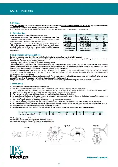
1/2Figure 1Figure 2Figure 31. PrefaceThe ILG/S gearbox is a sandwich manual override quarter turn gearbox for spring return pneumatic actuators . It is intended to be used for the manual operation of valves (e.g. butterfly valves) in pipelines.This manual is valid only for the standard ILG/S gearboxes. For special versions, quantities and model can differ.1.2 Handling and safety precautionsBe sure to read and understand this manual before installation and use of our standard ILG/S-gearbox.Storage: The gearboxes need to be stored in a safe way to avoid accidents. Avoid storage in areas subjected to high temperature extremes and/or areas subjected to high humidity and dust.Handling: Never drop the gearbox or expose it to strong impact.Correct use: Prior to installation, be sure the gearbox will NOT be overloaded during normal use. For this, check that the valve size and needed opening torque do not exceed the values given for the gearbox. For the maximum allowable torque on the gearbox, see table. InterApp is not responsible for any damage caused by incorrect use of the gearbox.Installation and operating: Not observing the rules as stated in this manual, can lead to damage and/ or personal injuries. The qualified personnel must be fully aware of the instructions as described in this manual. Only when the instructions are observed, correct operation of the gearboxes can be guaranteed.Disposal: Never put a gearbox at a general disposal unit. The gearbox has to be offered to a disposal depot for recycling. The iron parts can be used for recycling . The seals are of nitrile and can be used for plastic recycling.The grease may not be discharged to sewer- or surface water. It has to be disposed according to local regulations for incineration.2. Installation1 The gearbox is standard delivered in closed position.2 It is recommended to mount a handwheel on the input shaft prior to assembling the gearbox to the valve.3 Check if the bolt circle of the flanges (of gearbox and valve) coincides. Also check if the valve shaft and the bore of the coupling match.4 Make sure the valve is in the fully closed position. If not, close the valve before continuing.5 Put the gearbox in fully opened (!) position by turning the handwheel counterclockwise.6 In case of use of stud bolts for fixing the gearbox to the valve, it is recommended to screw them into the bottom flange of the gearbox prior to mounting the gearbox on top of the valve.7 The use of a gasket between the flange of the valve and gearbox is recommended.8 Put the drive shaft (see figure 1) into the gearbox. The size and shape of the connections can differ from the example in figure 1.9 Put the gearbox on top of the valve. Make sure the drive shaft is in the most left turned position (seen from the bottom side). See figure 2.10 The gearbox is mounted perpendicular to the valve (see figure 3).11Fix the gearbox to the valve with nut and ring. In case of use of bolts, for the maximum screw depth, see table below.1.1 Technical dataThe ILG/S gearboxes are of different types and sizes.Under normal conditions, the gearbox is maintenance free. The gearbox is greased and sealed for life. The maximum allowable input and output torques are listed in the following table.The gearboxes can be used at ambient temperatures from –20 to +85°C. Our standard gearbox reaches IP65 (dust- and waterspray proof). Cleaning can be done with a waterhose, but not a high pressure waterjet. For more specified information, you can contact our salesdepartement.12 The (spring-return) actuator can be mounted on top.13 The assembly is ready for adjustment (see next chapter).14 Before operating, be sure the gearbox is in opened position.2/2INSTALL-ILGS_1138© 2009 InterApp AG, all rights reserved InterApp AG Grundstrasse 24CH-6343 RotkreuzPhone +41 (0) 41 7982233Fax +41 (0) 41 7982234****************.netInterApp GermanyAVK Mittelmann Armaturen Schillerstrasse 50D-42489 WülfrathPhone +49 (0) 2058 901 01Fax +49 (0) 2058 901 110**********************InterApp Austria Kolpingstrasse 19A-1230 WienPhone +43 (0) 1 6162371-0Fax +43 (0) 1 6162371-99****************.net InterApp Italy Via Gramsci 29I-20016 Pero (MI)Phone +39 02 339371Fax +39 02 33937200****************.net InterApp VálvulasCalderón de la Barca 12E-28860 Paracuellos de Jarama Phone +34 (0) 91 6584360Fax +34 (0) 91 6581430****************.netAVK VálvulasPoligono Industrial Francoli, parcela 27E-46006 Tarragona Phone +34 977 543 008Fax +34 977 541 622*******************InterApp Singapore11, Changi North Street 1, #03-11Singapore 498823Phone +65 62141048Fax +65 62140481****************.netFigure 4enThe technical data are noncommittal and do not assure you of any properties. Please refer to our general sales conditions. Modifications without notice.3. Adjustment of the stops crewsThe gearbox is already mounted on top of the valve (see installation).1 With the valve in fully closed position turn handwheel counterclockwise toput the gearbox in opened (!) position. This may not affect the position of the valve (remains fully closed).2 Mount the (spring-return) actuator.3 Turn the handwheel clockwise to put the gearbox in fully closed position.When the full closed position can not be achieved, loosen the stops crew-close (see figure 4). Continue turning the handwheel until the valve is fully closed.4 Turn the screw back into the gearbox until blocked (handtight). Secure thestops crew–close with the counternut.5 Put the gearbox into the fully opened position by turning the handwheelcounter-clockwise.6 Use the actuator to put the valve in fully opened position. When the fully openposition can not be achieved, loosen the stops crew-open (see figure 4). Continue turning the handwheel counterclockwise, until the valve can be fully opened.7 Turn the stop-screw back into the gearbox until blocked (handtight). Securethe stops crew–open with the counternut.8 Depressurice the actuator.9 Close the valve completely, turning the handwheel clockwise.10 Put the gearbox into the fully opened position by turning the handwheelcounterclockwise.11 Adjustment completed. The gearbox is now ready for automatic operation.4. OperatingWith the gearbox correct installed, under normal circumstances the valve is operated by an actuator. The ILG/S gearbox allows manual operation (closing) of the valve in case of malfunction in the automatic actuator system.1 The gearbox is operated by handwheel.2 The valve is closed by turning the handwheel clockwise.3 Stop turning when the required valve position is achieved. The number ofrotations of the handwheel needed turn the valve from fully open to fully closed is stated in table below.4 When the valve can not be totally closed, first detect and solve the cause offailure.5 In case of malfunction of the gearbox, this one has to be replaced. Return thegearbox to your supplier for repair.6 When you do the repair in house, all replacement parts must be obtainedfrom the manufacturer to assure proper operation of the gearbox.7 The gearbox is self-braking. Therefore no fixation needs to be installed.8 When the malfunction is repaired, turn the handwheel until blocked.9The system is ready for use.。
气动系统的说明书第一节:引言气动系统是一种利用压缩空气作为动力源的系统,广泛应用于各个工业领域。
本说明书将详细介绍气动系统的组成部分、工作原理以及常见应用,旨在帮助读者更好地了解和使用气动系统。
第二节:气动系统的组成部分气动系统由以下组成部分构成:1. 压缩空气源:气动系统的动力来源通常是通过压缩机产生的压缩空气。
压缩空气源通常包括压缩机、冷却器和水分离器等。
2. 储气器:储气器用于储存压缩空气并保持恒定的供气压力,以满足系统的需求。
3. 气动执行元件:气动执行元件是气动系统中的关键部件,用于完成各种机械运动。
常见的气动执行元件包括气缸、气动阀门和气动马达等。
4. 气源处理单元:气源处理单元用于清洁、干燥和调节压缩空气,以确保气动系统的正常运行。
第三节:气动系统的工作原理气动系统的工作原理可以简述如下:1. 压缩空气通过压缩机产生,并通过管道输送至气源处理单元进行过滤、干燥和调压。
2. 经过气源处理单元处理后的压缩空气进一步储存于储气器中,以保持供气的稳定性。
3. 当系统需要执行机械运动时,通过打开气动阀门,压缩空气进入气缸或其他气动执行元件,从而推动执行元件的运动。
4. 当气动阀门关闭时,压缩空气被释放,气动执行元件恢复到原始位置。
第四节:气动系统的应用气动系统具有以下优点,因此在许多应用中得到了广泛的应用:1. 灵活性:气动系统可以轻松实现多种机械运动,并且具有较高的运动精度和重复性。
2. 安全性:与电动系统相比,气动系统在潮湿、易燃或易爆的环境中更安全可靠。
3. 成本效益:气动元件相对较便宜且易于获取,同时气动系统的维护成本也较低。
4. 可靠性:气动系统可以实现长时间的稳定运行,并且对瞬时负载的适应能力较强。
气动系统广泛应用于以下领域:1. 制造业:在自动化生产线中,气动系统常用于零件装配、搬运和加工等工序中。
2. 交通运输:气动系统常用于列车和汽车的制动系统、悬挂系统等。
3. 仪器仪表:气动系统可以用于控制和测量设备,如气动传感器等。


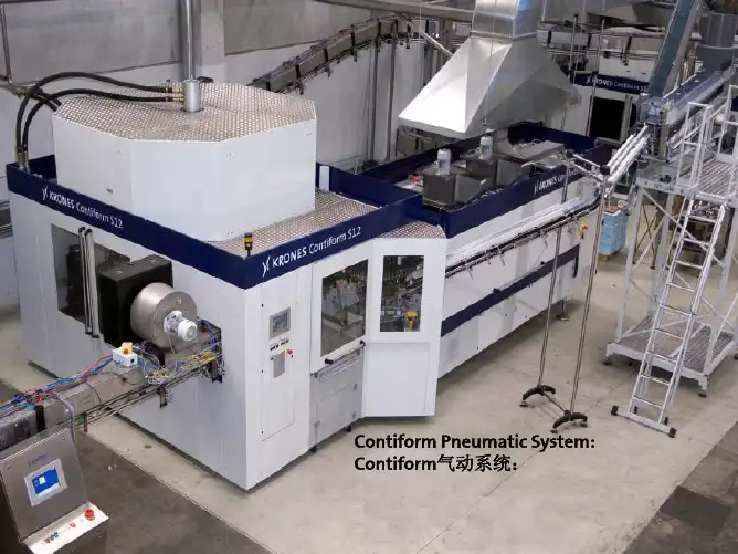
32Dose© SMC PneumaticsLift 1tJT c?■-2术培训•?原c 3PNEUMATIC SYSTEM 气动系统方向控制閥Cylinder 气缸Motor气马达主路脚匕设备Main Line Air 压缩机CompressorDirectional FBttr 过滤Control Valve Regulator 调压LubHeatw 润滑过滤器调压阀油雾器回系统图空气处理三联件过滤器实物图剖面图动作短片(0・N)恰途於皿O・N長巻用Hb空气处理三联件调压阀直动式调压阀先导式调压阀精密调压阀电气比例阀空气处理三联件油雾器毛细管阻尼膜油量调节器労油量单i诃向阀、空气单向阀实物图原理图驱动元件摆动气缸标准气缸特殊气缸回系统图标准气缸双动气缸的结构8•弹性挡圈7.防尘圈压板18.防尘圈16•安装螺母6•导向套1 •杆侧端盖5.活塞杆3•缸筒9.缓冲垫4•活塞13.活塞密封圈14.静密封圈15•耐磨环10.缓冲垫11 •标准气缸双动气缸的结构弹性挡圈2A.无杆侧端盖标准气缸双动气缸的结构短片一短片二标准气缸磁性开关及磁环标准气缸气缓冲1・缓冲套2•缓冲密封件3•缓冲针4•头端盖当缓冲套插入缓冲密封件时,正常的排气通道便会被堵塞,被困的空气被加压,而舒缓了活塞的惯性. 加压的空气只可通过缸盖上的一个小针阀控制的小孔排放,这就构成了缓冲行程的效果.气缓冲装置是由缓冲套,缓冲封圈和缓冲阀组成.动件演示直接安装实物图螺纹轴颈式安装实物图脚码安装实物图前法兰安装实物图后法兰安装耳环连接式安装实物图中间轴耳式安装标准气缸气缸的理论出力理论出力=活塞面积X 空气压力双动气缸产生的理论出力: 伸出:Fe^xo'xPg4缩回:Fr=^X (D 2- d 2)xPg。
=气缸缸径Pg 二空气压力(表压) d 二活塞杆直径 Fs 二弹簧出力单动气缸产生的理论出力: 伸出:Fe= ^xD 2xPg - Fs4标准气缸气缸的负载率所需出力负载率=颤丽^100%负载率的选取与负载的运动状态有尖,按一般的选取如下:气缸的缸径与行程标准气缸气缸的选择步骤程序5(缓冲形式) 程序7(气缸配件)程序3(气缸系列)程序1(缸筒内径)(安装形式)(磁性开关)程序6 程序4程序』如何决定缸筒内径尺寸■首先,请确认以下三个使用条件。
美国寿力产品LS25S机型带有进气蝶阀,部分配有螺旋阀,其气量调节系统的工作原理如下:气量调节系统的功能是根据客户用气量的大小,自动调节压缩机的进气量,以便达到供需平衡,稳定供气压力,节省能源。
对带螺旋阀的机组,当客户的用气量等于机组的额定排气量时,机组将在满负荷状态下运行,此时,控制进气量的蝶阀保持最大开度,螺旋阀的指针将指向最大位置(MAX);当用气量为机组额定排气量的100%到50%时,蝶阀全开,由螺旋阀动作自动调节供气量;当用气量为机组额定排气量的50%到40%时,螺旋阀全开,调节系统将自动控制进气蝶阀的开度进行气量调节;当客户停止用气时,蝶阀将自动关闭,停止进气,此时,机组将在较低的背压下运行,处于空载状态,螺旋阀的指针指向最小位置(MIN)。
对不带螺旋阀的机组仅由部分负载压力调节器通过控制进气蝶阀的开度进行气量调节,调节范围是100%~40%。
下面分四种不同的状态,以带螺旋阀的LS25S-300L型机组为例,详细说明气量调节系统的功能。
(1)起动阶段(轻载起动过程)控制进气阀的开合有两路气体分别是开启气路和关闭气路。
开启气路的主要组件是减压阀和启动电磁阀;关闭气路有加/卸载电磁阀和部分负载压力调节器等。
按下起动键,启动电磁阀和加/卸载电磁阀仍然保持失电,切断开启气路,打开关闭气路。
此时,进气阀在真空的作用下部分打开,少量空气进入压缩机,分离后的压缩空气又被循环阀引导回进气阀,分离器罐的压力逐渐建立。
电机处于Y形连接下轻载运行。
经设定时间后(一般为6秒),切换到△形连接下运行。
启动电磁阀和加/卸载电磁阀同时被切换为得电,打开开启气路,切断关闭气路,关闭循环阀,完全打开进气阀。
机组进入常规运行状态。
(2)常规运行当油气分离器内的压力超过3.4Bar时,最小压力阀打开,压缩机开始向外供气。
此时,进气阀保持最大开度,螺旋阀指针指向MAX位置。
机组在全负荷状态下运行。
只要系统内压力不超过7.0Bar,此状态将一直保持下去。
气动系统知识点总结气动系统是利用气体做工质传递能量和控制信号的一种自动控制系统。
它具有传动效率高、速度快、灵敏度高、结构简单、维护方便、价格低廉等优点,被广泛应用于各种机械设备中。
在工业自动化生产中,气动系统发挥着重要的作用。
本文将对气动系统的基本知识点进行总结,包括气动原理、气动元件、气动控制系统、气动传动系统等内容。
一、气动原理1. 气源气源是气动系统的能量来源,通常采用压缩空气。
压缩空气经过气源处理系统(包括滤清器、干燥器、油雾器)处理后成为清洁、干燥、无油的工作气源。
2. 压缩空气的处理压缩空气需要经过滤清器去除空气中的尘埃和杂质,干燥器去除水分,油雾器去除油雾,以保证气动系统的正常运行。
3. 压缩空气的传送压缩空气通过气源处理系统后,通过管道传送到气动执行元件。
4. 气动执行元件气动执行元件将压缩空气的能量转换成机械运动,常见的气动执行元件包括气缸、气动执行阀等。
5. 控制元件控制元件用于控制气源的开关、压力的调节以及气动执行元件的工作。
常见的控制元件包括手动阀、电磁阀、单向阀、调压阀等。
6. 气动传动系统气动传动系统是气动系统的核心部分,通过气源和控制元件的作用,将气动能量传递到被控对象上,实现对被控对象的控制。
二、气动元件1. 气缸气缸是最常见的气动执行元件,其工作原理是利用气源推动气缸活塞运动,将气源能量转换成机械能。
根据结构形式可分为单向作用气缸和双向作用气缸。
2. 阀门阀门是气动系统中的重要控制元件,用于控制气源的开关、气缸的运动方向、压力的调节等功能。
常见的阀门包括手动阀、电磁阀、比例阀、单向阀、调压阀等。
3. 气源处理元件气源处理元件包括滤清器、干燥器、油雾器等,用于对压缩空气进行处理,使其满足气动系统的要求。
4. 接头接头用于连接气源和气动元件,包括快速接头、螺纹接头、管接头等。
5. 气动管路气动管路是气源和气动执行元件之间的连接通道,通常采用聚氯乙烯、聚丙烯、铝合金等材料制成。
康斯博格气动腰托按摩系统介绍第一篇:康斯博格气动腰托按摩系统介绍会议纪录会议内容:基于DPCA以后会对座椅关键部件指定供应商的趋势,所以期望能与供应商进行一些专业上的交流,加强对产品技术特性的了解,为后续选择供应商作工作准备。
本次会议主要对腰托系统、按摩系统、通风系统及加热垫进行了技术交流。
一、腰托系统的交流Q:机械腰托与气动腰托的差别?A:气动腰托无支撑硬点、贴合性好、舒适性高;气动腰托具有可扩展性,在由两向变为四向时只需增加气袋、气管,成本增加少;同等情况下,2向气动腰托比机械腰托的价格超出不到5RMB。
Q:腰托系统支撑效果的评测?A:主要是测定反应速度(充气速度)测定 X向,气袋置于两平板间负载25KG,在20~30s内,达到行程20mm左右(2个气袋同时测定,不单独测试)测定Z向(对于四向腰托),Z向不作此类测试,在设计时会定义Z 向的跨度 Q:腰托行程的定义?A:腰托行程20mm指的是腰托单体的行程。
一般来讲,在装配到座椅上后的行程要求为8~10mm(SAEⅡ型假人测试)Q:腰托系统的体压分布如何评判?A:选取不同的人群样本,进行体压测试。
Q:要求腰托系统实现模块化的要求时,对边界(泡沫厚度、形状、簧架)要求有哪些?A:腰托系统的模块化是根据客户不同的输入,选择满足要求的气袋、气泵和电磁阀来组成整个腰托系统。
气动腰托易布置Q:腰托的保压标准?A:有两种评定方法(负载时):高度变化、气压变化一般来讲,日系车采用高度变化来评定,部分欧系车用气压变化。
PSA标准是采用气压变化来评定的康斯博格目前产品的性能:气压变化 1h:小于5%24小时:小于10%高度变化 1h:小于3%24小时:小于5% Q:腰托带有记忆功能时,记忆功能是怎么实现的?A:记忆的位置是用气压来关联的,记忆模块会记录这个位置的气压,通过气压传感器来实现Q:空载(人体没有靠着靠背上)时与负载时腰托系统如何检测(2种情况下传感器感知的压力不一样),从而使得腰托都能达到正确的记忆位置A:通常记忆功能的实现都是需要负载后来实现的,目前还不能在空载时精确的回复到记忆位置Q:两个气袋冲完气后压力差异?A:差异非常小(模具精度高、使用的同一气泵充气)二、按摩系统的交流Q:一次按摩循环是多长时间,按摩停止后如何再次启动?A:一个按摩循环一般设定为20分钟,按摩20分钟后会自动停止。
刘华 (本刊编委会委员)毕业于山东工业大学内燃机专业,现为威海职业学院汽车专业教授、高级工程师,哈尔滨工业大学车辆工程专业工学硕士;山东省教学名师,全国机械行指委汽车专指委委员;《汽车柴油机电控系统检修》国家级精品课、共享课负责人;“《柴油机电控高压共轨系统检修》新课程的构建与教学实践”省级教学成果二等奖第一完成人。
车辆可变进气VIS 系统详解◆文/山东 刘华图1 VIS 系统组成图2 叶片式真空泵 2016年全国职业院校技能大赛高职组“一汽—大众”杯汽车检测与维修赛项于2016年6月1日-2日在长春汽车工业高等专科学校举行,比赛采用实操考核形式,分为“汽车发动机系统检修”、“汽车电气系统检修”两个项目进行,考试车型为2012款迈腾1.8TSI+DSG 基本型。
其中“汽车发动机系统检修项目”在整车上同时设置了5个故障点,涵盖三个故障类型,一是启动时启动机不转动,此类型设置2个故障点:15供电继电器J329故障及起动机30接线柱无常电源;二是启动时启动机转动正常但发动机毫无着火迹象,此类型设置2个故障点:燃油泵控制单元J538的常电源缺失及点火线圈的总供电缺失;三是发动机运转不良,此处设置故障点为可变进气VIS 系统电磁阀连接的两根气管位置互换。
由于考试时间有限,大部分考生对VIS 系统的原理及检修方法准备不足,未能排除该故障。
常见的VIS 系统包含改变进气歧管的长度及改变进气歧管的横截面积等两种类型。
下文以一汽大众迈腾车(1.8TSI+DSG 基本型)、奇瑞A3车(1.8L 缸外喷射发动机)为例,详细介绍上述两个车型安装的VIS 系统的原理及检修方法。
可变进气VIS 系统(Variable Intake System)是利用发动机工作时进气管道的进气动态效应来提高进气终了的压力,从而提高进气效率,以达到在发动机转速范围内增大扭矩和功率之目的。
为便于分析,常将进气动态效应视为进气惯性效应和波动效应共同作用的结果。