CSU技术使用说明书V2.0
- 格式:pdf
- 大小:689.77 KB
- 文档页数:31
CS20 体积测量工具使用说明手册目录1.工具简介 (3)2.安装说明 (4)2.1.系统要求 (4)2.2.Package V olume安装 (4)2.3.硬件连接 (4)CS20 外观示意图 (4)3.相机标定 (6)3.1. 启动相机 (6)3.2. 相机标定 (6)3.3. 相机需要标定的情况说明 (7)3.3.1. 配置文件缺失或损坏 (7)3.3.2. 场景异常变动 (8)3.3.3. 场景过于复杂 (8)3.3.4.进行周期标定 (9)3.3.5.测量结果不准问题 (9)4.测试案例 (10)4.1.案例1:测量纸箱位于测试台之上 (10)4.2.案例2:被测物体直接放置地板之上且箱子位置不固定 (10)5.测试异常处理 (12)5.1.矮小包裹 (12)5.2.超大包裹 (12)1.工具简介工具名称:Package V olume工具说明:Package V olume是CS20系列的windows体积测量工具。
该工具主要用于测量快递包裹、纸箱、文件等体积数据。
测量精度:±1cm测量帧率:8fps左右测量形态:方形或异形(快递包装袋)包裹安装高度:800mm-1800mm(注:被测物体尽量不要超过安装高度的一半,且测量画面中不可有高出被测物体高度的物体,否则会影响测试准确度)可测量大小:根据安装高度而定安装高度1000mm时可测物体长宽最低可测(40mm*30mm*30mm);长宽数据大于100mm时:高度可测1-3mm文件袋2.安装说明2.1.系统要求当前Package V olume支持window10。
2.2.Package Volume安装Package V olume为绿色版本,无需单独安装。
图2.1 PackageVolume 测量工具软件截图2.3.硬件连接将CS20通过数据线与PC端的USB接口连接:CS20 外观示意图设备连接后搭测试环境:图2.2 相机安装示意图如图2.2所示为相机安装示意图,相机安装在工作台面正上方,相机视场垂直向下,对准工作台平面,为保证测量精准度,工作台平面和相机拍摄的方向尽量保持垂直。

图像比对软件设计说明标识:编号:版本:V2.0图像比对软件设计说明xxxx2012年3月图像比对软件设计说明拟制人:审核:会签批准:2011年3月xx日文档修改记录目次1 范围 (1)1.1 标识 (1)1.2 系统概述 (1)1.3 文档概述 (1)2 引用文档 (1)3 CSCI级设计决策 (1)3.1 输入/输出设计决策 (1)3.1.1图像比对软件的输入/输出数据流图 (1)3.1.2输入/输出说明 (2)3.1.3 CSCI的行为设计决策 (2)3.2 CSCI的数据库决策 (3)3.3 CSCI的安全性设计决策 (3)3.4 CSCI保密性与私密性设计决策 (3)3.5 CSCI其它设计决策 (3)4 CSCI体系结构设计 (3)4.1 CSCI部件组成 (3)4.2 执行概念 (5)4.3 接口设计 (6)4.3.1外部接口设计 (6)4.3.2内部接口设计 (8)5 CSCI详细设计 (14)5.1 主控CSU(CSCI_TXBD_CSU_ZK) (14)5.1.1设计决策 (14)5.1.2处理流程 (14)5.1.3内部数据 (15)5.1.4异常与错误处理 (16)5.2 序列图像显示CSU(CSCI_TXBD_CSU_XLTX) .. 17 5.2.1设计决策 (17)5.2.2处理流程 (17)5.2.3内部数据 (17)5.2.4异常与错误处理 (18)5.3 图像相关信息显示CSU (CSCI_TXBD_CSU_TXXXXS) (18)5.3.1设计决策 (18)5.3.2处理流程 (18)5.3.3内部数据 (18)5.3.4异常与错误处理 (18)5.4 导航图显示CSU(CSCI_TXBD_CSU_DHTXS) (19)5.4.1设计决策 (19)5.4.2处理流程 (19)5.4.3内部数据 (19)5.4.4异常与错误处理 (19)5.5 缩略图显示CSU(CSCI_TXBD_CSU_SLTXS) (19)5.5.1设计决策 (19)5.5.2处理流程 (20)5.5.3内部数据 (20)5.5.4异常与错误处理 (20)5.6 图像处理CSU(CSCI_TXBD_CSU_CL) (20)5.6.1设计决策 (20)5.6.2处理流程 (20)5.6.3内部数据 (21)5.6.4异常与错误处理 (21)5.7 图像标定CSU(CSCI_TXBD_CSU_BD) (22)5.7.1设计决策 (22)5.7.2处理流程 (22)5.7.3内部数据 (22)5.7.4异常与错误处理 (22)5.8 图像标注CSU(CSCI_TXBD_CSU_BZ) (22)5.8.1设计决策 (22)5.8.2处理流程 (23)5.8.3内部数据 (23)5.8.4异常与错误处理 (23)5.9 图像存储CSU(CSCI_TXBD_CSU_CC) (23)5.9.1设计决策 (23)5.9.2处理流程 (23)5.9.3内部数据 (23)5.9.4异常与错误处理 (23)5.10 图像输出CSU(CSCI_TXBD_CSU_TXSC) (23)5.10.1设计决策 (23)5.10.2处理流程 (23)5.10.3内部数据 (23)5.10.4异常与错误处理 (23)5.11 图像比对CSU(CSCI_TXBD_CSU_BDCL) (23)5.11.1设计决策 (23)5.11.2处理流程 (24)5.11.3内部数据 (25)5.11.4异常与错误处理 (25)5.12 比对结果显示CSU(CSCI_TXBD_CSU_BDJGXS) (26)5.12.1设计决策 (26)5.12.2处理流程 (26)5.12.3内部数据 (27)5.12.4异常与错误处理 (27)5.13 比对向导CSU(CSCI_TXBD_CSU_BDXD) (27)5.13.1设计决策 (27)5.13.2处理流程 (27)5.13.3内部数据 (28)5.13.4异常与错误处理 (28)5.14 数据维护CSU(CSCI_TXBD_CSU_SJWH) (28)5.14.1设计决策 (28)5.14.2处理流程 (28)5.14.3内部数据 (28)5.14.4异常与错误处理 (29)6 需求可追踪性 (29)7 名词解释 (30)III1 范围1.1 标识本文档的标题为“图像比对软件设计说明”。

CSU32P20用户手册带12-bit ADC的8位RISC OTP MCUREV 1.7版本历史目录版本历史 (2)目录 (3)1产品概述 (6)1.1功能描述 (6)1.2主要特性 (6)1.3选型表 (7)1.4PIN配置 (8)1.4.1SOP8/DIP8/MSOP8 PIN配置 (8)1.4.2MSOP10 PIN配置 (8)1.4.3SOP14/DIP14/TSSOP14 PIN配置 (9)1.4.4SOP16/TSSOP16/DIP16 PIN配置 (9)1.5引脚说明 (10)1.6CSU32P20与CSU8RP3119B/3117B/3115B/CSU8RP3215资源差异 (11)2标准功能 (12)2.1CPU核 (12)2.1.1存储器 (14)2.1.2状态寄存器 (16)2.1.3SFR (17)2.2时钟系统 (19)2.2.1概述 (19)2.2.2时钟框图 (19)2.2.3寄存器 (19)2.2.4内部高速RC时钟 (20)2.2.5内部低速wdt时钟 (20)2.3复位系统 (21)2.3.1上电复位 (23)2.3.2看门狗复位 (23)2.3.3窗看门狗复位 (23)2.3.4掉电复位 (23)2.3.5外部硬件复位 (24)2.3.6非法指令复位 (24)2.3.7EMC复位 (24)2.3.8寄存器说明 (24)2.4中断 (26)2.4.1中断概述 (26)2.4.2中断使能寄存器 (27)2.4.3中断标志寄存器 (29)2.4.4外部中断0 (31)2.4.5外部中断1 (31)2.4.6AD中断溢出 (34)2.4.7定时器0溢出中断 (34)2.4.8定时/计数器2溢出中断 (34)2.4.9定时/计数器3溢出中断 (34)2.4.10PUSH和POP处理 (34)2.5定时器0 (36)2.5.2定时器0寄存器列表 (36)2.5.3定时功能 (38)2.6I/O PORT (39)2.6.1GPIO上下拉电阻 (39)2.6.2PT1口 (39)2.6.3PT3口 (44)2.6.4PT5口 (47)3增强功能 (50)3.1H ALT和S LEEP模式 (50)3.2看门狗(WDT) (52)3.2.1看门狗定时器寄存器表 (52)3.2.2WDT定时器功能 (53)3.3窗看门狗(WWDT) (55)3.3.1WWDT特性 (55)3.3.2WWDT功能描述 (55)3.3.3寄存器描述 (57)3.4定时/计数器2 (59)3.4.1定时/计数器2概述 (59)3.4.2寄存器描述 (59)3.4.3定时/计数器功能 (63)3.4.4蜂鸣器 (63)3.4.5PWM (64)3.5定时/计数器3 (66)3.5.1寄存器描述 (66)3.5.2定时/计数器功能 (71)3.5.3蜂鸣器 (71)3.5.4PWM (72)3.5.5互补式PWM输出 (73)3.6模数转换器(ADC) (75)3.6.1寄存器描述 (75)3.6.2输入电压和SRAD输出数据的关系 (79)3.6.3转换时间 (79)3.6.4ADC采样时间 (81)3.6.5AD失调电压校正 (82)3.6.6数字比较器 (83)3.6.7内部测量VDD的电压 (84)3.75*8软件LCD (86)3.7.1寄存器描述 (86)3.7.2软件LCD实现方法 (86)3.8数据查表 (87)3.8.1读操作 (87)3.8.2寄存器描述 (87)3.9输入逻辑电平电压配置 (89)3.9.1寄存器描述 (89)3.10输出电流配置 (90)3.10.1寄存器描述 (90)3.11烧录模块 (91)3.12代码选项 (92)3.12.1OPTIION (92)4MCU指令集 (94)5典型应用 (112)5.1移动电源 (112)5.2其他应用 (112)6电气特性 (113)6.1极限值 (113)6.2直流特性(VDD=5V,T A=25ºC,如无其他说明则都是此条件) (113)6.3ADC特性(VDD=5V,T A=25ºC,如无其他说明则都是此条件) (114)6.432MH Z IRC时钟频率特性 (116)6.516MH Z IRC时钟频率特性 (116)6.68MH Z IRC时钟频率特性 (117)6.7WDT时钟频率特性 (117)6.8 2.0V掉电复位温度特性 (118)6.9 2.4V低电压复位温度特性 (118)6.10内部参考电压1.4V电压和温度特性 (119)6.11内部参考电压2.0V电压和温度特性 (119)6.12内部参考电压3.0V电压和温度特性 (120)6.13内部参考电压4.0V电压和温度特性 (120)6.14可靠性 (120)6.14.1ESD特性 (120)6.14.2Latch up (120)7封装图 (122)7.1SOP-8PIN (122)7.2DIP-8PIN (124)7.3MSOP-8PIN (126)7.4MSOP-10PIN (127)7.5SOP-14PIN (128)7.6DIP-14PIN (129)7.7TSSOP-14PIN (130)7.8SOP-16PIN (131)7.9TSSOP-16PIN (132)7.10DIP-16PIN (133)8单片机产品命名规则 (134)8.1产品型号说明 (134)8.2命名举例说明 (135)8.3产品印字说明 (135)9订货信息 (136)10附录 (137)10.1使用CSU32P20替换CSU3115B/CSU3117B/CSU3119B方法说明 (137)1产品概述1.1功能描述CSU32P20是一款带12-bit ADC的8位CMOS单芯片RISC MCU,内置2K×16位OTP程序存储器,104字节SRAM。

CS2000系统说明书目录第一章硬件系统 (3)1.1 系统主要特点 (4)1.2 实验对象组成结构 (4)1.3 控制台组成结构 (7)1.4 RS-485接口转换器与通讯电缆 (11)第二章MCGS组态系统 (13)2.1主控窗口 (13)2.2 设备窗口 (13)2.3 用户窗口 (14)2.4 实时数据库 (14)2.5 运行策略 (14)第一章硬件系统生产与生活的自动化是人类长久以来所梦寐以求的目标,在18世纪自动控制系统在蒸汽机运行中得到成功的应用以后,自动化技术时代开始了。
随着工业技术的更新,特别是半导体技术、微电子技术、计算机技术和网络技术的发展,自动化仪表已经进入了计算机控制装置时代。
在石油、化工、制药、热工、材料和轻工等行业领域中,以温度、流量、物位、压力和成分为主要被控变量的控制系统都称为“过程控制”系统。
过程控制不仅在传统工业改造中,起到了提高质量,节约原材料和能源,减少环境污染等十分重要的作用,而且已成为新建的规模大、结构复杂的工业生产过程中不可缺少的组成部分。
随着计算机控制装置在控制仪表基础上的发展,自动化控制手段也越来越丰富。
其中有在工业领域有着广泛应用的智能数字仪表控制系统、智能仪表加计算机组态软件控制系统、计算机DDC控制系统、PLC控制系统、DCS分布式集散控制系统、FCS现场总线控制系统等。
在现代化工业生产中,过程控制技术正为实现各种最优的技术经济指标、提高经济效益和劳动生产效率、改善劳动条件、保护生态环境等起到越来越大的作用。
CS2000型过程控制实验装置是根据我国工业自动化及相关专业教学特点,吸取了国外同类实验装置的特点和长处,并与目前大型工业装置的自动化现场紧密联系,采用了工业上广泛使用并处于领先的AI智能仪表加组态软件控制系统、DCS(分布式集散控制系统),经过精心设计、多次实验和反复论证后,推出的一套基于本科生、研究生教学和学科基地建设的实验设备。

中达系列开关电源维护手册在本手册中,我们简要介绍了目前我省常用的中达ES3000/MCS3000,ES5500/MCS6000及ES750/MCS1800系列开关电源系统的基本原理、产品性能,接着着重对系统参数配置、设定等日常操作及故障处理方法(同时提供部分实战案例供各位参考)进行汇编;最后是有关中达电源系统的维护要点及开关电源维护制度汇编。
第一节开关电源系统原理简介1.1常用中达开关电源系列及特点中达ES3000/MCS3000,ES5500/MCS6000及ES750/MCS1800系列高频开关直流电源系统,由交流配电单元(屏)、整流变换单元、直流配电单元(屏)及监控管理单元组成。
3000系列整流模块单机输出额定值为-48V/50A或+24V/100A,系统设计采用整流及配电综合型设计,每个机架含整流模块、监控单元及交直流配电,在目前基站使用较多。
ES750/MCS1800系列与3000系列结构类同,只是容量较小,适用边际网一类站所;ES5500/MCS6000系列直流供电系统,是由多部48V/100A(或24V/150A)整流模块与直流配电组合成整流低阻综合屏再配上交流配电盘和监控模块组成;适用大容量的局站等。
中达电源内置全智能型监控单元内装微处理器,针对系统输入、输出、模块状况、电池充放电、电池及环境温度等运作状况监控及警示。
备有RS-232接口供本地或远程通信用,具有三遥(遥讯、遥测、遥控)功能。
1.2中达电源整流模块工作原理中达整流模块其工作原理说明如下:经交流配电(屏)来的单相220V(5500/6000系列为三相380V)交流电源接入整流模块之后经过AC 断路器,保险丝等保护组件,进入EMI滤波器,单相(三相)交流电源经桥式整流器整流为直流后,再经主动式功率因素校正线路(PFC Boost Converter),经PFC控制器完成高功率因素(PF >0.99),低失真因素(THD <5%)之要求,产生一约400V(三相为530V)的直流电压供给直流对直流转换器使用。
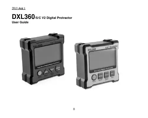
DXL360/S/C V2 Digital Protractor User GuideFeatures:1) DXL360S/C: High accuracy ±0.05°, high resolution 0.01°DXL360: ±0.1°, resolution 0.02°, detail check specification2) Dual and Single axis with user friendly LCD display angle3) Rechargeable4) V Shape metal case for easy to fit at the corner or pipe.5) 5 Side Magnetic base6) Audible alarming at settable angle range7) Any angle measurement *DXL360s/c only8) USB / Bluetooth to pc connection need adapter for DXL360 and DXL360s/c. SpecificationsAccuracy:DXL360S/C:0 to 20°: ± (0.05°)20 to 70°: ± (0.1°)70 to 90°: ± (0.05°)DXL360:0 to 20°: ± (0.1°)20 to 70°: ± (0.2°)70 to 90°: ± (0.1°)*After CalibratedMeasuring range:Single axis: 360°, Dual axis: ±40°Resolution:DXL360S/C: 0.01°DXL360: 0.02°Any Angle Measurement 0.5°Accuracy *DXL360s/c:Gyro Rotation Speed *DXL360s/c: <50°/sResponse time: <0.4 secondAudio sound:60dB @ 30cmZero offset drift angle per °C: 0.0058° (typical)Operating temperature: 0 to 50°CStorage temperature: -10 to 60°CUser Interface: Mono-color LCD with backlight Supply Power: Rechargeable Li-Polymer 3.7V Charger port:5V 500mA Mini type-B USB port Power Consumption: Standby: 10uA, Operation: 20mA. Standby Battery Life:4000 hoursOperating Battery Life: 40 hoursDimensions(in mm):70(L) x 70(W) x 23(H)Magnetic Base: affix at 4 cornerMagnetic Force: N48Weight: 120gramButton FunctionsButtonFunction DescriptionsNormal Mode MENU ModePOWER In normal operation, this button turns the deviceON/OFF.Serves as theescape key atmenu modeZERO When pressed, the current reading is set tozero; subsequent measurements are relative tothis reading. The LCD will show the icon toindicate the device is in zero mode.Press and hold for 3 seconds to enable ordisable sound. The icon on LCD will bedisplaced accordingly. The buzzer alarmingcould be set at different accuracy level. Refer tosection “Angle Alarming”.Serves as theupward key foroption selection.HOLD When pressed, the current value will freeze; theunit icon flashes to indicate the readingis on hold.Serves as thedownward key atmenu modeSET Press and hold for 3 seconds to enter MENUmode, for set mode options.Serves as the Setkey.ANGLE *DXL360S/Conly Any angle measurement start button. Refer tosection “Any Angle”Press and hold for 3 seconds to enter MENUmode, for set mode options.Serves as the Setkey.LCD Icons RepresentationsBattery status indication iconsThese icons indicate the battery level. There are 3 levelsrepresenting empty, half and full.In dual-axis mode, the LCD displays the direction of tiltgraphically. It will show as E bubble to display the direction of tiltDegree mode. Flash when unit is in HOLD modemm/M, the height of one end for 1m long plate.Gradient % mode. Flash when unit is in HOLD mode*DXL360S/C OnlySound notification on.Blank as offShow this logo as relative value is showing. When the Zerobutton is pressed, the unit reset current angle to zero.Direction of tilt icons, show the tilt angle directionDual-Axis Mode. Both the X and Y axis angle will be showed.Dual axis mode measures inclination up to +-40 degree for eachaxis before it automatically switch to single axis mode.Single Axis Mode. Measure slope up to +-90 degree.The triangle icon indicates the direction of tilt with respect to thebottom right corner of the unit.Battery ChargingIt has a built in Lithium Ion rechargeable battery. A standard charger is supplied that the input voltage is 110V to 240V AC, 50/60Hz, and the output is 5V DC, 500mA. The charger operating procedure is list below:1) Plug the Charger into AC socket, the RED indicator on the charger should turnedON,2) Plug the USB charging cable to the Charger,3) Insert the other end of the USB cable to the unit,4) The battery icon on the LCD blinks to indicate charging in process. Upon chargingcomplete, the icon stops blinking.5) The charging time is approx. 3 hours.The unit could also be charged by connecting the USB cable to the unit and a computer’s USB port. This has the same effect when charging the unit with the provided adaptor. Note: When the unit is turned OFF, and plug in the USB charge cable, the LCD will no show anything, it is NORMAL. Once the unit is turned ON, the battery icon should flash indicating the unit is in charging mode.Relative/ Absolute MeasurementRelative MeasurementLCD Icon:Absolute MeasurementLCD Icon: BlankRelative and Absolute Mode Switching:1 Pre ss and release the “ZERO” key to set the relative measurement zeropoint2 Press and release the “ZERO” key to cancel the relative zero point andback to absolute measurement mode.Hold FunctionHolding Mode:LCD Icon blinking:Holding function:1. Press and release the “HOLD” key to activate holding function, digit willfreeze.2. Press and release the “HOLD” key to cancel the holding function.Auto Power OffFor no movement in 30 minutes, the unit will power off.Or we can set to never sleep mode at below instruction.Power auto off setting:1. Press and hold “SET” / “ANGLE” key and enter MENU mode2. Select “POWER” by “ZERO” and “HOLD” key, press “SET” key to enter Powermode3. Scroll “NEVER” or “30MIN” by “ON/OFF” and “HOLD” key4. Press “SET” key to confi rm NEVER or 30MIN (30 minutes) sleepRestore Factory SettingWhen you find that the unit is abnormal, you can restore the unit to factory setting.All calibration setting will be restored to factory setting.*Not suggest restore to factory setting in normal status, for accuracy drift, please follow Calibration. After factory set, please redo calibration to ensure the accuracy. Restore to factory setting:1. Press and hold “SET ” / “ANGLE ” key and enter MENU mode2. Select “FACTORY SET” by “ZERO ” and “HOLD” key, press “SET ” key to enter FACTORY SET mode3. Scroll “YES” or “NO” by “ZERO ” and “HOLD” key4. Press “SET ” key to confirmAngle Alarming Alarming Mode: LCD Icon:Alarming Angle setting:1. Press and hold “SET ” / “ANGLE ” key and enter MENU mode2. Select “BUZZER” by “ZERO ” and “HOLD” key,press “SET ” or “ANGLE ” key to enter BUZZER settingPress and hold “ZERO ” and “HOLD” key for fast scrolling the digit. 3. Press “SET ” or “ANGLE ” to enter setting valueBUZZER>SINGLE : 0 0 . 0 0 DUAL. X: 0 0 . 0 0 DUAL. Y: 0 0 . 0 0 RANGE : 0 0 . 5 0 ACTIVE : IN OUTSINGLE Vertical / Single axis mode alarming angle (Degree)DUAL.X Horizontal/ Dual axis mode X axis alarming angle (Degree)DUAL.Y Horizontal/ Dual axis mode Y axis alarming angle (Degree)RANGE The range (Degree)that will trigger the audible alarmingFor example: SINGLE. set to 20.00RANGE set to 01.00While the unit is in +19° to +21°or -19° to -21°, the unit will alarm ACTIVE IN or OUT to set the alarm will alarm in of range or out of rangeCalibrationCalibrate the unit, once you found that there is accuracy drift on the unit. You can verify the accuracy at below step:At Step1, you measured X and Y value, X1 and Y1At Step2, you measured X2 and Y2, in theory X1=-X2, Y1=-Y2.If the error is too large, you can enter calibration mode to eliminate the errorAccuracy drift is causing by large ambient temperature change (5 to 10 Degree Celsius)or the unit has been dropped.Calibration Procedure:Step 1: Press and hold the “SET” or “ANGLE” key enter Menu mode. Select “Calibration” mode, press “SET”. Place the unit on a flat table (no need perfect level table) LCD display “CALIBRATE DUAL AXIS PRESS SET”, press “SET” and buzzer will beep; wait until the beep sound stop. While the buzzer is beeping keep the unit stable.Step 2: Then rotate the unit 180 degree with the other side against the same place.Press the Set button again, and wait for the beep finished.Step 3:LCD display “CALIBRATE HORIZONTAL PRESS SET”. Place the unit horizontal like the picture “STEP 3” and then press “SET”, wait until the beep sound stop.Step 4: Then rotat e the unit 180 degree at the same place. Press the “ZERO” button again, and wait for the beep finished.Step 5:LCD display “CALIBRATE VERTICAL PRESS SET”, mention that the ON/OFF Key at upper side, hold on a flat wall. And then press “SET” Key. Wait for the “Beep” sound stop.Step 6: Then rotate the unit 180 degree with the other side against the same place of wall (ON/OFF Key at upper side). Press the Set button again, and wait for the beep finished. Now, the LCD should go back to the selection menu. The calibration is done, by selecting “Back” to go back for normal operationANY ANGLE measurement: *DXL360S/C onlyAny angle measurement is using gyro technique.You can measure the angle between two faces, not only in earth gravity direction.1) Press Angle key at the first face, and then rotate slowly and must keep the rotationaxis to another testing face2) It will then show the angle once you not move the unit.The rotation axis:Any Angle Measurement Method:Example: Measure angle between two wooden walls is 88.9°Calibrate Gyro *DXL360S1) Place Unit At Flat Table And then Press Set2) Flip 360 degree in clockwise and then press setPlease rotate slowly to increase the accuracy3) Place unit at flat table and then press set4) Flip 360 degree counter clockwise and then press setPlease rotate slowly to increase the accuracyPC CommunicationIt has a PC data logging function.For DXL360SC you can directly plug the USB cable between PC and protractor by miniUSB cableFor DXL360/S You can not directly plug the USB cable between PC to protractor by a general USB cable.You need to optional purchase the PC adapter SVRS232You can continue to data logging X and Y inclination data to PC.Sampling time is around 2 Hz.Specification:1) RS232 Com Port 9600 baud rate2) USB connection ( include a RS232 to USB adapter)3) Format will output ASCII: example for x is 0, Y is -88.88 X+0000Y-8888 Detail can visit our website or contact our sales person.DXL360/S/C V2 数字角度尺使用说明书产品特点:1) DXL360S/C: 高精度±0.05°, 高分辨率0.01°DXL360: 精度±0.1°, 分辨率0.02°, 详情参阅说明书。
JB-MH-CH8500 型气体灭火控制器使用手册(VER1.0)西安西核彩桥实业科技有限公司前言西安西核彩桥实业科技有限公司是专业从事火灾自动探测报警、消防联动控制系统产品和楼宇自动化控制产品的专业化生产厂家,集开发、生产、销售和服务于一体。
企业位于西安市高新技术产业开发区,是陕西省高新技术企业。
公司已通过ISO9001 质量体系认证和中国消防产品质量监督认证。
西安西核彩桥实业科技有限公司是在原军工企业的基础上改制而成的现代化企业,实力雄厚,拥有一流的专业技术队伍和先进的生产加工设备,以优质的产品和遍及全国的销售服务网络服务社会。
成立以来,公司一直本着“品质优良、用户满意、科技创新、持续发展”的质量方针,以人为本,科学管理,产品广泛应用于石油、电信、移动、钢铁、学校等国家重点行业和大型楼宇场馆,并以可靠的产品、优质的服务,良好的信誉赢得了设计部门和用户的好评,产生了良好的社会效益。
公司在自身拥有完备火灾报警系统的同时,积极参与国际市场,与美国盛赛尔公司( SYSTEMSENSOR)有着长期、密切的技术交流与合作,产品完全与盛赛尔公司产品配套,可满足我国及其他国家高、中、低端等不同领域的需求。
目录1. 产品说明⋯⋯⋯⋯⋯⋯⋯⋯⋯⋯⋯⋯⋯⋯⋯⋯⋯⋯⋯⋯⋯⋯⋯31.1 技术规格.⋯⋯⋯⋯⋯⋯⋯⋯⋯⋯⋯⋯⋯⋯⋯⋯⋯⋯⋯⋯. 31.2 技术指标⋯⋯⋯⋯⋯⋯⋯⋯⋯⋯⋯⋯⋯⋯⋯⋯⋯⋯⋯⋯.. 31.3 结构特征.⋯⋯⋯⋯⋯⋯⋯⋯⋯⋯⋯⋯⋯⋯⋯⋯⋯⋯⋯⋯. 42. 使用说明⋯⋯⋯⋯⋯⋯⋯⋯⋯⋯⋯⋯⋯⋯⋯⋯⋯⋯⋯⋯⋯⋯⋯52.1 主机状态指示灯⋯⋯⋯⋯⋯⋯⋯⋯⋯⋯⋯⋯⋯⋯⋯⋯⋯.. 52.2 主机按键⋯⋯⋯⋯⋯⋯⋯⋯⋯⋯⋯⋯⋯⋯⋯⋯⋯⋯⋯⋯.. 62.3 功能⋯⋯⋯⋯⋯⋯⋯⋯⋯⋯⋯⋯⋯⋯⋯⋯⋯⋯⋯⋯⋯⋯.. 62.4 主机操作⋯⋯⋯⋯⋯⋯⋯⋯⋯⋯⋯⋯⋯⋯⋯⋯⋯⋯⋯⋯ (8)3. 安装与接线⋯⋯⋯⋯⋯⋯⋯⋯⋯⋯⋯⋯⋯⋯⋯⋯⋯⋯⋯⋯⋯ (11)3.1 安装尺寸⋯⋯⋯⋯⋯⋯⋯⋯⋯⋯⋯⋯⋯⋯⋯⋯⋯⋯⋯⋯.. 113.2 端子接线示意图⋯⋯⋯⋯⋯⋯⋯⋯⋯⋯⋯⋯⋯⋯⋯⋯⋯.. 123.3 接线说明⋯⋯⋯⋯⋯⋯⋯⋯⋯⋯⋯⋯⋯⋯⋯⋯⋯⋯⋯⋯.. 124. 系统配置⋯⋯⋯⋯⋯⋯⋯⋯⋯⋯⋯⋯⋯⋯⋯⋯⋯⋯⋯⋯⋯⋯⋯134.1 配置说明⋯⋯⋯⋯⋯⋯⋯⋯⋯⋯⋯⋯⋯⋯⋯⋯⋯⋯⋯⋯.. 134.2 配套器件⋯⋯⋯⋯⋯⋯⋯⋯⋯⋯⋯⋯⋯⋯⋯⋯⋯⋯⋯⋯.. 135. 故障分析与排除⋯⋯⋯⋯⋯⋯⋯⋯⋯⋯⋯⋯⋯⋯⋯⋯.⋯⋯⋯.. 146. 产品成套⋯⋯⋯⋯⋯⋯⋯⋯⋯⋯⋯⋯⋯⋯⋯⋯⋯⋯⋯⋯⋯⋯⋯147. 附图⋯⋯⋯⋯⋯⋯⋯⋯⋯⋯⋯⋯⋯⋯⋯⋯⋯⋯⋯⋯⋯⋯⋯⋯⋯161.产品说明JB-MH-CH8500 型气体灭火控制器是我公司按照GB16806-2006 《消防联动控制系统》研制开发的新产品,操作界面简单明了,易于用户操作使用。
国电南自Q/GDNZ.J.01.72-2000标准备案号:1539- 2000PSL 620C系列数字式线路保护技术说明书国电动份GUODIAN NANJING AUTOMATION CO.,LTDPSL620C数字式线路保护装置技术说明书V4.30国电南京自动化股份有限公司2005年12月版本声明本技术说明书适用于以下版本的保护程序:PSL621C距离保护版本: 4.53PSL621C零序重合闸保护版本: 4.52PSL622C高频保护版本: 4.10PSL623C过流零序重合闸保护版本: 4.53PSL626C过流距离重合闸保护版本: 2.82PSL627C过流重合闸保护版本: 2.82产品说明书版本修改记录表1098765432 V4.3 增加具备双以太网通信口(或三以太网)、RS485串行通信口、V4.52 2005.12 就地打印串行通讯口、PSView调试分析软件串行通讯口1 V4.0 增加装置整体结构图、面板布置图、结构安装图等 V4.50 2003.9 序号 说明书版本修 改 摘 要 软件版本号 修改日期* 技术支持:电话(025)51183140传真(025)51183144* 本说明书可能会被修改,请注意核对实际产品与说明书的版本是否相符* 2005年12月 第1版 第1次印刷目 录1 概述 (1)1.1适用范围 (1)1.2功能配置及型号 (1)1.3性能特点 (1)2 技术性能及指标 (3)2.1额定电气参数 (3)2.2技术性能及指标 (3)2.3环境条件 (4)2.4绝缘性能 (4)2.5电磁兼容性能 (5)2.6机械性能 (5)3 PSL621C线路保护装置 (6)3.1功能及原理 (6)3.1.1 启动元件 (6)3.1.2 选相元件 (6)3.1.3 距离保护 (6)3.1.4 零序保护 (12)3.1.5 重合闸继电器 (14)3.1.6 失灵启动 (16)3.1.7 合闸加速保护 (16)3.1.8 交流电压电流异常判断 (17)3.1.9 过流保护 (18)3.1.10 低周减载、低压减载 (18)3.2硬件构成 (20)3.2.1 硬件配置 (20)3.2.2 各模件说明 (22)3.3定值与整定 (31)3.3.1 装置整定项目与有关参数整定范围 (31)3.3.2 整定计算及整定方法简介 (33)4 PSL622C线路保护装置 (37)4.1功能及原理 (37)4.1.1 高频保护 (37)4.2硬件构成 (44)4.2.1 硬件配置 (44)4.2.2 各模件说明 (45)4.3定值与整定 (46)4.3.1 装置整定项目与有关参数整定范围 (46)4.3.2 整定计算及整定方法简介 (47)5 PSL623C线路保护装置 (49)5.1功能及原理 (49)5.2硬件构成 (50)5.2.1 硬件配置 (50)5.2.2 各模件说明 (51)5.3定值与整定 (52)5.3.1 装置整定项目与有关参数整定范围 (52)5.3.2 整定计算及整定方法简介 (54)6 PSL626C 线路保护装置 (56)6.1功能及原理 (56)6.2硬件构成 (60)6.2.1 硬件配置 (60)6.2.2 各模件说明 (61)6.3定值与整定 (65)6.3.1 装置整定项目与有关参数整定范围 (65)6.3.2 整定计算及整定方法简介 (66)7 PSL627C 线路保护装置 (69)7.1功能及原理 (69)7.2硬件构成 (70)7.2.1 硬件配置 (70)7.2.2 各模件说明 (71)7.3定值清单及整定说明 (72)7.3.1 装置整定项目与有关参数整定范围 (72)7.3.2 整定计算及整定方法简介 (73)8 信息记录和分析 (75)9 与变电站自动化系统配合 (75)10 事件信息一览表 (76)1 概述1.1 适用范围PSL 620C系列数字式线路保护装置是以距离保护、零序保护和三相一次重合闸为基本配置的成套线路保护装置,并集成了电压切换箱和三相操作箱,适用于110KV、66KV或35KV输配电线路。
iPACS-5612配电终端技术说明书版本:V2.00江苏金智科技股份有限公司前言非常感谢您选用江苏金智科技股份有限公司(简称金智科技,股票代码002090)生产的iPACS-5612配电终端使用说明书。
本手册是该系列保护测控装置说明书,期望它能为您的工作带来帮助。
本说明书仅供设计选型参考,与实际产品可能存在细微差别,因此不建议作为工程设计依据。
建议工程设计时向我公司设计人员索取相关设计图纸。
如需相关产品、服务和支持的更多信息,请访问金智科技网站/。
本公司有权对本说明书的内容进行定期变更,恕不另行通知。
变更内容将会补充到新版本的说明书中。
如您需要更新版本,敬请与我公司联系。
_____________________________________________________________版权所有,请勿翻印、复印说明书版本号:V2.00目录一、 iPACS-5612D配电终端技术说明书二、 iPACS-5612T配电终端技术说明书三、 iPACS-5612F配电终端技术说明书iPACS-5612D配电终端技术说明书版本:V2.00江苏金智科技股份有限公司目录1 概述 (1)1.1应用范围 (1)1.2主要功能 (1)1.3硬件结构 (1)1.4主要特点 (1)2 技术参数 (2)2.1机械及环境参数 (2)2.2电气参数 (2)2.3主要技术指标 (2)3 电磁兼容及绝缘试验 (3)3.1电磁兼容 (3)3.2绝缘试验 (5)4 功能介绍 (5)4.1遥控、遥测、遥信功能 (5)4.2参数设置功能 (5)4.3装置自检 (5)4.4电源失电保护功能 (5)4.5对时功能 (6)4.6手动操作功能 (6)4.7SOE纪录及上报功能 (6)4.8故障检测及故障判别功能 (6)4.9遥测越限检测及判别功能 (6)4.10馈线停电自动上传数据功能 (6)4.11通信功能 (6)4.12当地调试功能 (7)4.13输入输出回路安全防护功能 (7)5 装置参数及整定说明 (7)5.1监控参数 (7)5.2遥信参数 (9)5.3保护定值 (10)5.4遥测配置参数 (11)5.5直流参数 (11)5.6串口通讯参数设定 (11)5.7电度精度调整 (12)5.8交流调整 (12)5.9交流精度参数设定 (12)5.10直流精度自动调整 (12)5.11直流精度参数设定 (12)5.12装置初始化 (12)6 装置信息显示 (12)6.1测量值显示 (12)6.2数字量显示 (14)6.3报告显示 (15)6.4通信状态显示 (16)6.5程序版本显示 (16)7 手控操作 (16)8 时间设置 (17)9 报告清除 (17)10 特殊功能开入说明 (17)11 装置产生的虚遥信说明 (17)12 遥控信号说明 (18)13 遥控板配置说明 (18)14 液晶板说明 (18)15 装置接线端子与说明 (18)15.1模拟量输入 (19)1 概述1.1 应用范围iPACS-5612D为用于10KV开闭所内馈线自动化终端单元,可就地在开关柜安装亦可集中组屏。
A p p e n d i x AAppendix ACabling the 3512 DSU/CSUIntroductionleased lines, dial lines, and a Network Management System, and it describes port,connector, and cable interfaces and pinouts.3512. For more information, contact your Motorola representative. NOTE : For DTE cable pinouts, refer to your DTE manual.DSU/CSU must be braided, shielded cables with metal, shielded hoods to ensure compliance with FCC and CISPR requirements relative to emitting Radio Frequency Interference (RFI) to other sensitive electronic equipment. Contact your authorized Motorola sales representative to determine which cables are appropriate.Table A-1.Common 3512 DSU/CSU Cables for Port 1Application Electrical Interface Type: DB25 (m) to...ProductCode LengthDCE to DTE EIA 232DB25 (f) straight-through adapter 3103715 ft DCE to DTE EIA 232DB25 (m) straight-through adapter 6618615 ft DCE to DCE EIA 232DB25 (m) crossover 3103415 ft DCE to DTE V .35V .35 (f) straight-through adapter 48523 6 ft DCE to DTE V .35V .35 (m) straight-through adapter 77999 6 ft DCE to DCEV .35V .35 (f) straight-through adapter, and V .35 (m) to V .35 (m) crossover 48523 892606 ftTable A-2 shows communications cables for Ports 2, 3, and 4.Table A-3 shows telco cables that connect the 3512 to DDS wall jacks.Table A-4 shows cables that connect the 3512 NC IN and NC OUT ports to an NMS.Table A-2.Common 3512 DSU/CSU Communications Cables for Ports 2 - 4Application Electrical Interface Type ProductCode Length DCE to DTE EIA 232DB26 (m) to DB25 (f) straight-through adapter 26975920755 ft 10 ft DCE to DTE EIA 232DB26 (m) to DB25 (m) straight-through adapter 9203515 ft DCE to DCE EIA 232DB26 (m) to DB25 (m) crossover adapter 48043DCE to DCEEIA 232DB26 (m) to DB26 (m) crossover adapter 26977 5 ft DCE to Digital SW56 V .35 (Port 2 only)DB26 (m) to V .35 (m) crossover to switched digital restoral unit 48032 or 480391 ft 5 ft DCE to DCE Data UnitEIA 232(Port 2 only)DB26 (m) to DB25 (m) A/B switch crossover to restoral unit480381 ftDB26 refers to the EIA 232-D Alternate 26-pin (subminiature) connector.Table A-3.3512 DSU/CSU - Service Provider CablesProduct CodeFrom Product:To: 6 ft 15 ft 30 ft 50 ftDDS Line Port DDS Network (Mod-6) 1 77965DDS Network (Spade)48601DDS Network (RJ48S Mod-8)2696516-pin modular is mechanically, but not electrically, compatible with RJ11 PSTN connectorTable A-4.3512 DSU/CSU Cables to Network Management SystemProduct Code From Product:To:6 ft 15 ft 30 ft50 ftNC IN Port(f, 8-pin DIN, DCE)9300 Junction Box (SDL8) DTE 92199DB25 (f)403854038740388DB26 (f)403864038940390NC OUT Port(f, 8-pin DIN, DTE)3512 NC IN (f, 8-pin DIN, DCE)403804038140382Table A-5 shows cables that connect the 3512 restoral feature to a service-provider wall jack.Table A-6 provides information for ordering network connections and DDS lines.Table A-5.3512 DSU/CSU Integral Restoral Interface CablesProduct Code From Product:To: 6 ft 15 ft 30 ft50 ftSLR RJ45S Mod-8 (ALT)Dial Line (Mod-6) 1 99068Dial Line (RJ45S Mod-8)26967SW 56 (or DDS) RJ48 Mod-8 (ALT)4-wire SW 56 or DDS Network:(RJ48S)(Spade)(Mod 6) 126967486017796516-pin is mechanically, but not electrically, compatible with the RJ11 PSTN connector.Table A-6.Communications Line and Service Ordering InformationInterface USOC Jack Connector REN/Service Code Facility Interface Code2.4-kbps digital interface RJ48S 6.0F 04DU5-244.8-kbps digital interface RJ48S 6.0F 04DU5-489.6-kbps digital interface RJ48S 6.0F 04DU5-9619.2-kbps digital interface RJ48S 6.0F 04DU5-19256-kbps digital interface RJ48S 6.0F 04DU5-56 Public Switched Digital Service (PSDS), for SW 56 feature :56-kbps digital interface RJ48SPSDS Type 1 Public Switched Telephone Network (PSTN), for SLR feature:Permissive RJ11C 0.2B 02LS2Programmable RJ45S or RJ41S 0.2B02LS2Table A-7 provides information required when ordering network connections and telephone lines.Table A-7.Telecommunications Regulatory-Ordering InformationCountry3512 DSU/CSU Data Item ValueU.S.FCC Registration Number AT9USA-61595-DD-NU.S.Ringer Equivalence Number (REN)0.2BCanada Load Number for 3512 with SLR4Canada DOC Certification Number725 5221 ACanada Connection Arrangement Code CA45AIn the U.S.A., the REN determines the number of devices that can be connected to a telephone line. Excessive RENs on a line may result in the devices not ringing in response to an incoming call. Contact the service provider to determine the maximum REN sum for the calling area; in general, it should not exceed five.In Canada, the Load Number assigned to each terminal device denotes the total load percentage to be connected to a telephone loop used by the device to prevent overloading. The loop termination can consist of any combination of devices as long as their total Load Numbers do not exceed 100.Pin InterfacesTable A-8.DTE Connector PinoutsDB25 or DB26(Ports 1-4)EIA/TIA 232-D V.351Frame Ground Frame Ground2Transmit Data+Transmit Data3Receive Data+Receive Data4Request To Send Request To Send5Clear To Send Clear To Send6Data Set Ready Data Set Ready7Signal Ground Signal Ground8Carrier Detect Carrier Detect9Not used Not used10Not used Not used11Not used Not used12Not used Not used13Not used–Transmit Data Clock14Not used–Transmit Data15Transmit Data Clock+Transmit Data Clock16Not used-Receive Data17Receive Data Clock+Receive Data Clock18 (Port 1 only)Loop 3 Control Loop 3 Control19Not used– Receive Data Clock20Data Terminal Ready Data Terminal Ready21Loop 2 Control Loop 2 Control22Not used Not used23Not used– External Transmit Clock24External Transmit Clock+ External Transmit Clock25Test Mode Test Mode26Not used Not usedNOTE: Port 1: DB25 connector; Ports 2-4: DB26 subminiature connectorsTable A-9 shows how to connect the 3512’s DDS 8-pin RJ48S to an RJ11 wall jack.Table A-10 shows the 3512’s ALT connector pinouts for SLR and SW 56 operation.Table A-11 shows NC IN and NC OUT port pin assignments.Table A-9.RJ48S to RJ11 Cable PinoutsRJ48S 8-Pin Modular Jack Description RJ11 6-Pin Modular Wall Jack to PSTN 1Transmit (Ring)32Transmit (Tip)47Receive (Tip)28Receive (Ring)5Table A-10.Service Provider Connector PinoutsALT Pin SLRSwitched 56 1Transmit (Ring)2Transmit (Tip)34Ring 5Tip 67PR Receive (Tip)8PCTransmit (Ring)Table A-11.NC Terminal Interface Signal Pinouts (8-pin DIN Connector)Pin Signal Description NC IN (DCE)NC OUT (DTE) 2Transmit Data (TXD)Transmits serial digital data fromDTE.InputOutput 3Receive Data (RXD)Serial digital data available to the DTE receiver. Uses async data; has no clock.OutputInput4Request To Send (RTS)Active level to the DCE to transmit. Inactive level when transmission is not required.InputOutput7Signal Ground Common signal and DC powerground (common return).8Data Carrier Detect (DCD)Active level from the DCE when a received input (analog) signal isdetected.OutputInputNOTE:The NC connector uses only the pins listed here.。
超声切割止血刀系统产品说明书REV A.0瑞奇外科器械(中国)有限公司目录第一章概述 (5)第二章超声切割止血刀系统的组成及工作原理 (6)第一节 CSUS6000型超声切割止血刀系统结构组成示意图 (6)1、产品名称 (6)2、产品型号规格 (6)3、CSUS6000型主机 (6)4、驱动柄 (6)5、刀头 (6)6、FSW2型脚踏开关 (7)7、刀头功率水平 (7)第二节、操作说明 (8)第三节、开包装须知 (9)第三章系统的安装和运行 (10)第一节、系统启动 (10)第二节、系统运行 (11)第三节、系统关机 (15)第四章---故障检查和排除方法 (16)第一节、音响指示器和故障提示音 (16)第二节、故障代码 (16)第五章---产品的维护和保养方法 (17)第一节、主机和推车的清洁处理 (17)第二节、脚踏开关的清洁处理 (17)第三节、驱动柄的消毒和灭菌处理 (17)第四节、可重复使用刀头的消毒和灭菌处理 (17)第六章---安全和功能测试 (18)第一节、安全测试 (18)第二节、功能测试 (18)第七章---警告和注意事项 (19)第一节、有关系统的警告和注意事项 (19)第二节、有关刀头的警告和注意事项 (20)第八章---标识 (21)第九章---系统技术条件 (22)第十章---售后服务和承诺 (24)任何用户在使用本仪器之前,必须仔细阅读本手册!第一章概述任何用户在使用本产品之前,必须仔细阅读本文,本文告诉用户在使用时必须谨慎地注意操作步骤、可能导致异常的操作、可能对本产品或人身造成伤害的危险操作。
若发生本文所规定必须避免的操作而导致所有异常现象对本产品或人身造成伤害,本公司不承担安全、可靠性及性能保证责任!本公司也不会对此类故障给予免费维修!适应症该产品适用于对需要控制出血和最小程度热损伤的软组织进行切开。
禁忌症该产品不适用于骨切除、输卵管结扎、神经外科及3mm以上血管闭合手术。