格力多联机GMV内机(R410A)H系列
- 格式:doc
- 大小:2.89 MB
- 文档页数:24
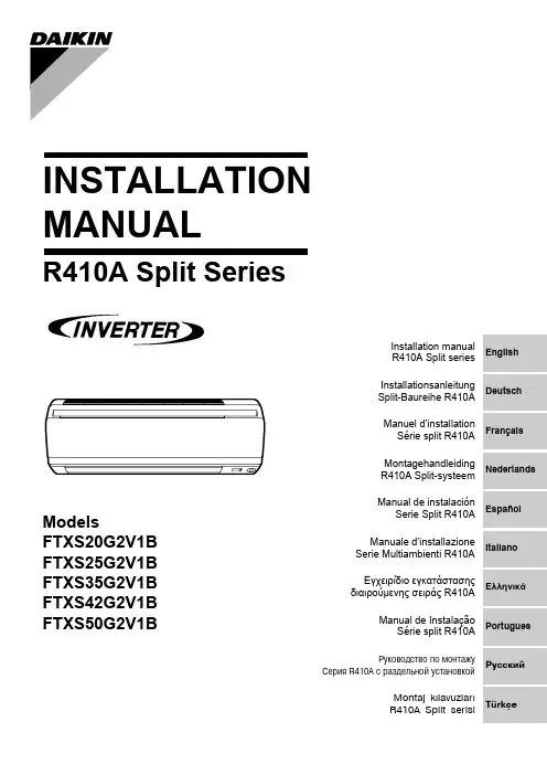
INSTALLATION MANUALR410A Split SeriesModelsFTXS20G2V1B FTXS25G2V1B FTXS35G2V1B FTXS42G2V1BFTXS50G2V1BDeutschFrançaisNederlandsEspañolItalianoΕλληνικÜPortuguesРóссêийEnglishTürkçeInstallation manual R410A Split series Montaj kýlavuzlarý R410A Split serisiInstallationsanleitung Split-Baureihe R410A Manuel d’installation Série split R410A Montagehandleiding R410A Split-systeem Manual de instalaciónSerie Split R410A Manuale d’installazione Serie Multiambienti R410A Εγχειρßδιο εγκατÜστασηòδιαιροýìενηò σειρÜò R410AManual de Instalação Série split R410AРóêоводство по монтажóСерия R410A с раздельной óстановêойU m e d a C e n t e r B l d g ., 2-4-12, N a k a z a k i -N i s h i ,K i t a -k u , O s a k a , 530-8323 J a p a n0G 2V 1B , F T X S 25G 2V 1B , F T X S 35G 2V 1B , F T X S 42G 2V 1B , F T X S 50G 2V 1BI N I N D U S T R I E S , L T D .S h i n r i S a d a M a n a g e r Q u a l i t y C o n t r o l D e p a r t m e n t 1s t . o f N o v . 2008L o w V o l t a g e 2006/95/E C E l e c t r o m a g n e t i c C o m p a t i b i l i t y 2004/108/E C *D A I K I N .T C F .015 L 3/08-2007K E M A Q u a l i t y B .V .74736-K R Q /E M C 97-4957Safety Precautions•The precautions described herein are classified as WARNING and CAUTION. They both contain important informa-tion regarding safety. Be sure to observe all precautions without fail.•Meaning of WARNING and CAUTION noticesWARNING....Failure to follow these instructions properly may result in personal injury or loss of life.CAUTION.....Failure to observe these instructions properly may result in property damage or personal injury, which may be serious depending on the circumstances.•The safety marks shown in this manual have the following meanings:Be sure to follow the instructions. Be sure to establish an earth connection. Never attempt.•After completing installation, conduct a trial operation to check for faults and explain to the customer how to operate the air conditioner and take care of it with the aid of the operation manual.WARNING•Ask your dealer or qualified personnel to carry out installation work.Do not attempt to install the air conditioner yourself. Improper installation may result in water leakage, electric shocks or fire.•Install the air conditioner in accordance with the instructions in this installation manual.Improper installation may result in water leakage, electric shocks or fire.•Be sure to use only the specified accessories and parts for installation work.Failure to use the specified parts may result in the unit falling, water leakage, electric shocks or fire.•Install the air conditioner on a foundation strong enough to withstand the weight of the unit.A foundation of insufficient strength may result in the equipment falling and causing injury.•Electrical work must be performed in accordance with relevant local and national regulations and with instructions in this installation manual. Be sure to use a dedicated power supply circuit only.Insufficiency of power circuit capacity and improper workmanship may result in electric shocks or fire.•Use a cable of suitable length.Do not use tapped wires or an extension lead, as this may cause overheating, electric shocks or fire.•Make sure that all wiring is secured, the specified wires are used, and that there is no strain on the terminal con-nections or wires.Improper connections or securing of wires may result in abnormal heat build-up or fire.•When wiring the power supply and connecting the wiring between the indoor and outdoor units, position the wires so that the control box lid can be securely fastened.Improper positioning of the control box lid may result in electric shocks, fire or over heating terminals.•If refrigerant gas leaks during installation, ventilate the area immediately.Toxic gas may be produced if the refrigerant comes into contact with fire.•After completing installation, check for refrigerant gas leakage. Toxic gas may be produced if the refrigerant gas leaks into the room and comes into contact with a source of fire, such as a fan heater, stove or cooker.•When installing or relocating the air conditioner, be sure to bleed the refrigerant circuit to ensure it is free of air, and use only the specified refrigerant (R410A).The presence of air or other foreign matter in the refrigerant circuit causes abnormal pressure rise, which may result in equipment damage and even injury.•During installation, attach the refrigerant piping securely before running the compressor.If the compressor is not attached and the stop valve is open when the compressor is run, air will be sucked in, causing abnormal pressure in the refrigeration cycle, which may result in equipment damage and even injury.•During pump-down, stop the compressor before removing the refrigerant piping.If the compressor is still running and the stop valve is open during pump-down, air will be sucked in when the refrigerant piping is removed, causing abnormal pressure in the refrigeration cycle, which may result in equipment damage and even injury.•Be sure to earth the air conditioner. Do not earth the unit to a utility pipe, lightning conductor or telephone earth lead.Imperfect earthing may result in electric shocks.•Be sure to install an earth leakage breaker.Failure to install an earth leakage breaker may result in electric shocks or fire.CAUTION•Do not install the air conditioner at any place where there is a danger of flammable gas leakage.In the event of a gas leakage, build-up of gas near the air conditioner may cause a fire to break out.•While following the instructions in this installation manual, install drain piping to ensure proper drainage and insu-late piping to prevent condensation.Improper drain piping may result in indoor water leakage and property damage.•Tighten the flare nut according to the specified method such as with a torque wrench.If the flare nut is too tight, it may crack after prolonged use, causing refrigerant leakage.AccessoriesChoosing an Installation Site•Before choosing the installation site, obtain user approval.1.Indoor unit.•The indoor unit should be sited in a place where:1)the restrictions on installation specified in the indoor unit installation drawings are met,2)both air intake and exhaust have clear paths met,3)the unit is not in the path of direct sunlight,4)the unit is away from the source of heat or steam,5)there is no source of machine oil vapour (this may shorten indoor unit life),6)cool (warm) air is circulated throughout the room,7)the unit is away from electronic ignition type fluorescent lamps (inverter or rapid start type) as they may shorten the remote controller range,8)the unit is at least 1 metre away from any television or radio set (unit may cause interference with the picture or sound),9)install at the recommended height (1.8m).2.Wireless remote controller.1)Turn on all the fluorescent lamps in the room, if any, and find the site where remote controller signals are properly received by the indoor unit (within 7 metres).2)Make the dipswitch settings. Set according to the type of unit purchased by the customer. The default settings are on the heat pump side.•For cooling only (Outdoor unit model: RKS)Set the dipswitches on the cooling only side.•For heat pump (Outdoor unit model: RXS)Check that the dipswitches are on the heat pump side.If they are set on the cooling only side, move them to the heat pump side.Installation Tips1.Removing and installing front panel.•Removal methodHook fingers on the panel protrusions on the left and right of the main body, and open until the panel stops. Slide the front panel sideways to disengage the rotating shaft. Then pull the front panel toward you to remove it.•Installation method2.Removing and installing front grille.•Removal method1)Remove front panel to remove the air filter.2)Remove the front grille.3)In front of the {{{of your other hand.When there is no work space because the unit is close to ceilingCAUTIONBe sure to wear protection gloves.Place both hands under the center of the front grille, and while pushing up, pull it toward you.•Installation method1)Install the front grille and firmly engage the upper hooks (3 locations).2)Install 2 screws of the front grille.3)Install the air filter and then mount the front panel.3.How to set the different addresses.When 2 indoor units are installed in 1 room, the 2 wireless remote controllers can be set for different addresses.1)Remove the metal plate electrical wiring cover.(Refer to the Removal/attachment methods of metal plate electrical wiring covers .)2)Cut the address jumper (JA) on the printed circuit board.3)Cut the address jumper (J4) in the remote controller.4.When connecting to an HA system.(Wired remote controller, central remote controller etc.)1)Remove the metal plate electrical wiring cover.(Refer to the Removal/attachment methods of metal plate electrical wiring covers .) 2)Attach the connection cord to the S21 connector and pull theharness out through the notched part in the figure.3)as it was, and pull the harness around, as shown in the figure.Installation TipsIndoor Unit Installation DrawingsCAUTION1)Do not hit or violently push the Intelligent-eye sensor. This can lead to damage and malfunction.2)Do not place large objects near the sensor. Also keep heating units or humidifiers outside the sensor’s detection area.Indoor Unit Installation1.Installing the mounting plate.•The mounting plate should be installed on a wall which can support the weight of the indoor unit.1)Temporarily secure the mounting plate to the wall, make sure that the panel is completely level, and mark the boringpoints on the wall.2)Secure the mounting plate to the wall with screws.Recommended mounting plate retention spots and Dimensions2.Boring a wall hole and installing wall embedded pipe.•For walls containing metal frame or metal board, be sure to use a wallembedded pipe and wall cover in the feed-through hole to prevent possible heat, electrical shock, or fire.•Be sure to caulk the gaps around the pipes with caulking material to prevent water leakage.1)Bore a feed-through hole of 65mm in the wall so it has a down slope toward the outside.2)Insert a wall pipe into the hole.3)Insert a wall cover into wall pipe.4)After completing refrigerant piping, wiring, and drain piping, caulk pipe hole gap with putty.3.Installing indoor unit.3-1.Right-side, right-back, or right-bottom piping.1)Attach the drain hose to the underside of the refrigerant pipes with an adhesive vinyl tape.2)Wrap the refrigerant pipes and drain hose together with an insulation tape.3)4)(Refer to Installation tips.)5)tape.)6)catch on the edge of the indoor unit.Indoor Unit Installation3-2.Left-side, left-back, or left-bottom piping.1)Attach the drain hose to the underside of the refrigerant pipes with adhesive vinyl tape.2)Be sure to connect the drain hose to the drain port in place of a drain plug.3)Shape the refrigerant pipe along the pipe path marking on the mounting plate.4)Pass drain hose and refrigerant pipes through the wall hole, then set the indoor unit on mounting guide.5)Pull in the interconnecting wires.6)Connect the inter-unit piping.7)Wrap the refrigerant pipes anddrain hose together with insulation tape as right figure, in case of setting the drain hose through the back of the indoor unit.8)While exercising care so that the interconnecting wires do not catch indoor unit, press the bottom edge of indoor unit with both hands until it is firmly caught by the mounting plate hooks. Secure indoor unit to the mounting plate with screws (M4 × 12L).3-3.Wall embedded piping.Follow the instructions given under 1)Insert the drain hose to this depth so it won’t be pulled out of the drain pipe..4.Wiring., install as described in the installation manual supplied with the Multi outdoor unit.1)Strip wire ends (15mm).2)Match wire colours with terminal numbers on indoor and outdoor unit’s terminal blocks and firmly screw wires to the corresponding terminals.3)Connect the earth wires to the corresponding terminals.4)Pull wires to make sure that they are securely latched up, then retain wires with wire retainer.5)In case of connecting to an adapter system. Run the remote controller cable and attach the S21.6)Shape the wires so that the service lid fits securely, then close service lid.WARNING1)Do not use tapped wires, strand wires, extensioncords, or starburst connections, as they may cause overheating, electrical shock, or fire.2)Do not use locally purchased electrical parts inside the product. (Do not branch the power for the drain pump, etc., from the terminal block.) Doing so may cause electric shock or fire.5.Drain piping.1)Connect the drain hose, as described right.2)Remove the air filters and pour some water into the drain pan to check the water flows smoothly.3)When drain hose requires extension, obtain an extension hose commercially available.Be sure to thermally insulate the indoor section of the extension hose.4)When connecting a rigid polyvinyl chloride pipe (nominal diameter 13mm) directly to the drain hose attached to the indoor unit as withembedded piping work, use any commercially available drain socket (nominal diameter 13mm) as a joint.Refrigerant Piping Work, install as described in the installation manual supplied with the Multi outdoor unit.1.Flaring the pipe end.1)Cut the pipe end with a pipe cutter.2)Remove burrs with the cut surface facing downward so that the chips do not enter the pipe.3)Put the flare nut on the pipe.4)Flare the pipe.5)Check that the flaring is properly made.WARNING1)Do not use mineral oil on flared part.2)Prevent mineral oil from getting into the system as this would reduce the lifetime of the units.3)Never use piping which has been used for previous installations. Only use parts which are delivered with the unit.4)Do never install a drier to this R410A unit in order to guarantee its lifetime.5)The drying material may dissolve and damage the system.6)Incomplete flaring may cause refrigerant gas leakage.2.Refrigerant piping.CAUTION1)Use the flare nut fixed to the main unit. (To prevent cracking of the flare nut by aged deterioration.)2)To prevent gas leakage, apply refrigeration oil only to the inner surface of the flare. (Use refrigeration oil for R410A.)3)Use torque wrenches when tightening the flare nuts to prevent damage to the flare nuts and gas leakage.Align the centres of both flares and tighten the flare nuts 3 or 4 turns by hand. Then tighten them fully with the torque wrenches.2-1.Caution on piping handling.1)Protect the open end of the pipe against dust and moisture.2)All pipe bends should be as gentle as possible. Use a pipe bender for bending.2-2.Selection of copper and heat insulation materials.•When using commercial copper pipes and fittings, observe the following:1)Insulation material: Polyethylene foamHeat transfer rate: 0.041 to 0.052W/mK (0.035 to 0.045kcal/(mh•°C))Refrigerant gas pipe’s surface temperature reaches 110°C max.Choose heat insulation materials that will withstand this temperature.2)Be sure to insulate both the gas and liquid piping and to provide insulation dimen-sions as below.3)Use separate thermal insulation pipes for gas and liquid refrigerant pipes.Pump Down OperationIn order to protect the environment, be sure to pump down when relocating or disposing of the unit.1)Remove the valve cap from liquid stop valve and gas stop valve.2)Carry out forced cooling operation.3)After 5 to 10 minutes, close the liquid stop valve with a hexagonal wrench.4)After 2 to 3 minutes, close the gas stop valve and stop forced cooling operation.How to force cooling operation mode■Using the indoor unit operation/stop buttonPress the indoor unit operation/stop button for at least 5 seconds. (Operation will start.)•Forced cooling operation will stop automatically after around 15 minutes. To force a test run to stop, press the indoor unit operation/stop button.■Using the main unit’s remote controller 1)Press the “operation/stop” button. (Operation will start.)2)Press the temperature button and the “operation select” button at the same time.3)Press the “operation select” button twice.( will be displayed and the unit will enter test run mode.)4)Press the “operation select” button to return the operation mode to cooling.•Test run mode will stop automatically after around 30 minutes. To force a test run to stop, press the operation/stop button.CAUTION1)After closing the liquid stop valve, close the gas stop valve within 3 minutes, then stop the forced operation.Gas side Liquid side Gas pipe thermal insulation Liquid pipethermal insulation 20/25/35/42 class50 class 20/25/35/42class 50 classO.D. 9.5mm O.D. 12.7mm O.D. 6.4mm I.D. 12-15mm I.D. 14-16mm I.D. 8-10mmMinimum bend radius Thickness 10mm Min.30mm or more 40mm or more 30mm or moreThickness 0.8mm (C1220T-O)Trial Operation and Testing1.Trial operation and testing.1-1Measure the supply voltage and make sure that it falls in the specified range.1-2Trial operation should be carried out in either cooling or heating mode.■For Heat pump•In cooling mode, select the lowest programmable temperature; in heating mode, select the highest programmable temperature.1)Trial operation may be disabled in either mode depending on the room e the remote controller for trial operation as described below.2)After trial operation is complete, set the temperature to a normal level (26°C to 28°C in cooling mode, 20°C to 24°C in heating mode).3)For protection, the system disables restart operation for 3 minutes after it is turned off.■For Cooling only•Select the lowest programmable temperature.1)Trial operation in cooling mode may be disabled depending on the room e the remote controller for trial operation as described below.2)After trial operation is complete, set the temperature to a normal level (26°C to 28°C).3)For protection, the unit disables restart operation for 3 minutes after it is turned off.1-3Carry out the test operation in accordance with the Operation Manual to ensure that all functions and parts,such as louver movement, are working properly.•The air conditioner requires a small amount of power in its standby mode. If the system is not to be used for some time after installation, shut off the circuit breaker to eliminate unnecessary power consumption.•If the circuit breaker trips to shut off the power to the air conditioner, the system will restore the original operation mode when the circuit breaker is opened again.2.Test items.Test itemsSymptom(diagnostic display on RC)CheckIndoor and outdoor units are installed properly on solid bases.Fall, vibration, noiseNo refrigerant gas leaks.Incomplete cooling/heating function Refrigerant gas and liquid pipes and indoor drain hose extension are thermally insulated.Water leakage Draining line is properly installed.Water leakage System is properly earthed.Electrical leakage The specified wires are used for interconnecting wire connections.Inoperative or burn damage Indoor or outdoor unit’s air intake or exhaust has clear path of air.Stop valves are opened.Incomplete cooling/heating function Indoor unit properly receives remote controller commands.InoperativeThe heat pump or cooling only mode is selectable with the dipswitches of the remote controller.Remote controller malfunctioning。
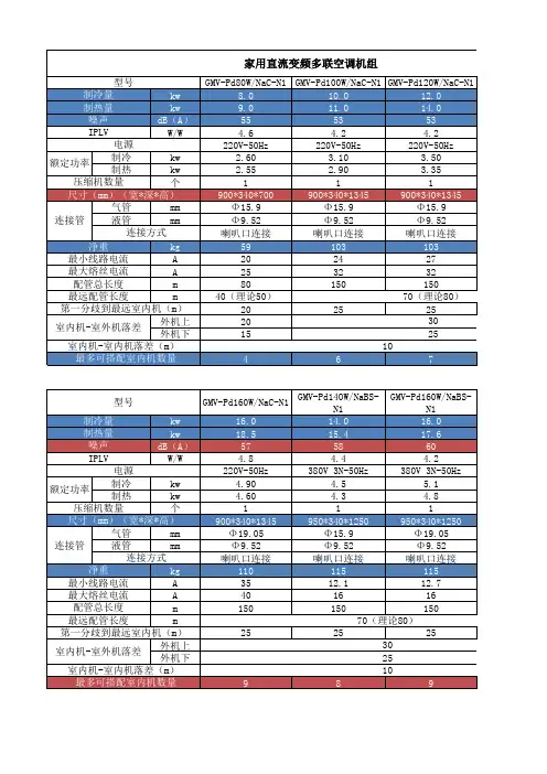
格力空调Tops系列多联机组技术文件格力电器第一部分系统外机性能与规格1、本机组设计实行标准GB/T 18837-20022、以上冷量测试工况:室内干球/湿球温度(27/19℃).室外干球/湿球温度(35/24℃);以上制热量测试工况:室内干球/湿球温度(20/15℃).室外干球/湿球温度(7/6℃).3、根据最大熔丝电流来选择空气开关.根据最小线路电流来选择电气配线规格。
3、系统外机安装注意事项(1)机组安装基础:必须是水泥或钢结构.应能承受机器的运行重量.并能隔音及震动.且上平面是水平的。
机组的安装基础应预留排水槽。
(2)机组运行环境:安装处应能确保机器免受暴晒和雨淋;应尽量免受火、易燃品、腐蚀性气体或废气的影响;应预留通风空间;应采取适当的措施.尽可能减小震动和噪音。
4、外机外形尺寸及安装维修空间单位:mm 第二部分系统内机性能与规格1、本机组设计实行标准GB/T 18837-2002。
2、机组风量是子环境温度20℃/16℃、内机最高风挡下测试。
3、额定测试条件:制冷:室内环境温度27℃(干球)/19℃(湿球)、室外环境温度35℃(干球)/24℃(湿球);制热:室内环境温度20℃(干球)/15℃(湿球)、室外环境温度7℃(干球)/6℃(湿球);.3、根据最大熔丝电流来选择空气开关.根据最小线路电流来选择电气配线规格。
2、室内机安装注意事项(1)机组安装基础:确保顶部吊杆、天花板、建筑物结构等有足够强度来承受机组重量。
(2)安装处应能确保机器免受暴晒和雨淋;应尽量免受火、易燃物、腐蚀性气体或废气影响;应预留通风空间;应采取适当措施尽可能减小噪音和震动。
3、产品外形尺寸及安装维修空间第三部分产品电气及接地部分注意事项注意:空调机必须可靠接地.若接地不正确会导致触电或火灾。
一、电气布置◆按国家布线规则进行安装。
◆电源一定要使用额定电压及空调机组专用电源。
◆电源线应有可靠固定.以免接线端子受力.请不要用力拉动电源线。
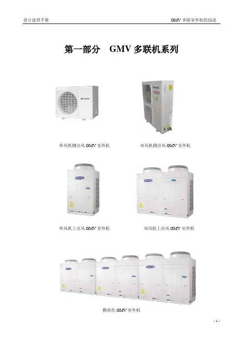
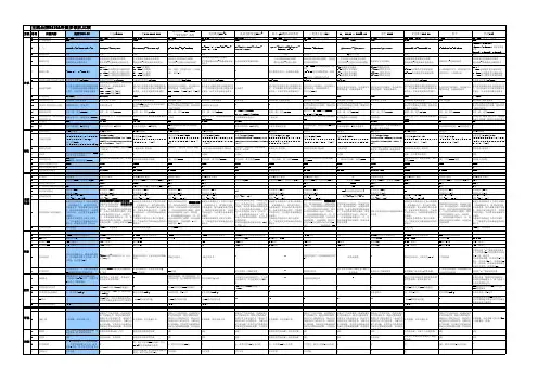
第一部分GMV多联机系列模块化GMV室外机双风机上出风GMV室外机单风机上出风GMV室外机双风机侧出风GMV室外机单风机侧出风GMV室外机- 1 -第一篇GMV多联室外机组第一章GMV多联室外机组综述一、GMV系列室外机族谱图(请参见下一页)二、GMV系列多联机组产品特点◆机型丰富、选择自由a. 强大的室外机阵容格力的GMV多联机目前已开发出的系列包括数码多联、直流变频多联、交流变频多联、智能变频多联、智能多联等,各大系列又因为用户的需求和机组本身的特点可划分为多个子系列,可满足几乎所有需要应用多联机组的场合。
b. 灵活多变的室内外机搭配GMV系列多联空调机组一台室外机可任意搭配不同类型、不同容量的室内机。
按房间的用途和装修特点,可以选择的室内机型式包括高静压风管式、超薄风管式、四面出风天井式、单面出风天井式、挂壁式等。
广泛应用于不同规模、不同用途的现代家居空间、商业场所、办公环境以及日益增多的高档别墅、公寓、复式楼等。
尤其适合于负荷变化较大的环境。
◆长距离的冷媒管路GMV多联机的室内外机之间可实现高落差和长配管连接。
机组允许落差和配管长度由于室外机之间的区别而有所不同(详见后续各章节中具体的机型高落差和长配管参数)。
◆设计、安装高效a.设计简化GMV多联机组是一次冷媒系统,由冷媒配管直接传递冷量。
相对于传统的二次冷媒系统,GMV无需庞大笨重的配套系统和复杂的管路设计。
b.安装轻便无需专用机房,简单的配管和布线系统、轻便的室内/室外机,让少数安装人员在很短的时间内就可以轻松完成安装。
轻量型的室外机使您甚至可以利用大楼内的电梯进行搬运。
室外机运行时震动很小,楼层无需另外加固。
- 2 -格力中央空调设计选型手册 GMV 多联室外机组综述- 3 -GMV 多联机型谱图数码多联数码多联系列(GR )* GMV-R100W/H GMV-R120W/H GMV-R140W/H(S) GMV-R160W/H(S) GMV-R200W2/B GMV-R220W2/BGMV-R260W2/B GMV-R300W2/B GMV-R420W3/B GMV-R450W3/A GMV-R560W4/AGMV-R620W4/AGMV-R860W6/A GMV-R900W6/A外形图数码多联R410A 系列(GR )*GMV-R120W/Na GMV-R160W/NaSGMV-R260W2/Na GMV-R300W2/NaGMV-R450W3/NaGMV-R560W4/Na GMV-R600W4/NaGMV-R860W6/Na GMV-R900W6/Na外形图模块化数码系列(GRm)*GMV-Rm224W/D GMV-Rm280W/DGMV-Rm335W/DGMV-Rm450W/D GMV-Rm600W/DGMV-Rm448W2/D GMV-Rm504W2/D GMV-Rm560W2/D GMV-Rm615W2/DGMV-Rm670W2/DGMV-Rm728W3/D GMV-Rm784W3/D GMV-Rm840W3/D GMV-Rm895W3/D GMV-Rm950W3/D GMV-Rm1005W3/DGMV-Rm1050W2/D GMV-Rm1200W2/DGMV-Rm1350W3/D GMV-Rm1500W3/DGMV-Rm1650W3/D GMV-Rm1800W3/D外形图R410A 模块化数码系列(GRm)*GMV-Rm224W/Na GMV-Rm280W/Na GMV-Rm335W/Na GMV-Rm400W/Na GMV-Rm450W/Na GMV-Rm504W/Na GMV-Rm560W2/Na GMV-Rm615W2/NaGMV-Rm670W2/Na GMV-Rm730W2/Na GMV-Rm800W2/Na GMV-Rm850W2/Na GMV-Rm900W2/Na GMV-Rm954W2/NaGMV-Rm1008W3/Na GMV-Rm1070W3/Na GMV-Rm1135W3/Na GMV-Rm1200W3/Na GMV-Rm1250W3/Na GMV-Rm1300W3/Na GMV-Rm1350W3/Na GMV-Rm1405W3/Na GMV-Rm1458W3/Na GMV-Rm1512W3/Na GMV-Rm1600W4/Na GMV-Rm1650W4/Na GMV-Rm1700W4/Na GMV-Rm1750W4/Na GMV-Rm1800W4/Na GMV-Rm1854W4/Na GMV-Rm1908W4/Na GMV-Rm1962W4/NaGMV-Rm2016W4/Na外形图超低温热泵系列(GRe ) GMV-Re120WGMV -Re150W/S GMV -Re160W/SGMV-Re280W2外形图变频多联直流变频系列(GPd)*GMV-Pd50W/Na GMV-Pd70W/NaGMV-Pd100W/Na GMV-Pd120W/NaGMV-Pd140W/Na GMV-Pd160W/Na GMV-Pd160W/NaS GMV-Pd180W/NaS外形图模块化直流变频系列(GPdm)*GMV-Pdm224W/Na GMV-Pdm280W/Na GMV-Pdm335W/Na GMV-Pdm400W/NaGMV-Pdm450W/Na GMV-Pdm504W2/Na GMV-Pdm560W2/Na GMV-Pdm615W2/Na GMV-Pdm670W2/Na GMV-Pdm730W2/Na GMV-Pdm785W2/Na GMV-Pdm850W3/Na GMV-Pdm900W3/N GMV-Pdm950W3/Na GMV-Pdm1005W3/Na GMV-Pdm1065W3/Na GMV-Pdm1130W3/Na GMV-Pdm1180W3/Na GMV-Pdm1235W3/Na GMV-Pdm1300W3/Na GMV-Pdm1350W3/Na GMV-Pdm1405W4/Na GMV-Pdm1456W4/Na GMV-Pdm1520W4/Na GMV-Pdm1570W4/Na外形图交流变频系列(GP )*GMV-P120W/H(S)GMV-P140W/HS GMV-P160W/HSGMV-P180W/HSGMV-P280W2/D外形图智能变频系列(GPJ )* GMV-P110W2/J GMV-P120W2/JGMV-P125W2/J GMV-P135W2/JGMV-P150W2/J外形图设计选型手册GMV多联机系列- 4 -格力中央空调◆控制方便a. 远程布线远程布线系统可将多台室内机和室外机串联起来,最长通讯距离根据机型不同可达到1~4公里。
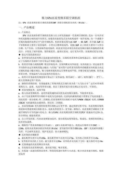
格力GPd直流变频多联空调机组注:GPd 直流变频多联空调机组搭配GMV 多联空调机组室内机(R410A)。
一、产品概述1、产品特点GPd 直流变频多联空调机组是格力自主研发的最新一代变频空调机组,是由一台风冷室外机连接数台相同或不同型式、容量的直接蒸发式室内机构成单一制冷系统,向一个或数个区域直接提供处理后空气的空调机组;机组容量范围为10.0kW ~ 90.0kW,其中20.0kW 以下容量机组主要用于家居场所、小型办公楼和商场等,而20.0kW 以上机组主要用于大型办公楼、生产车间、大型商场等商用场所。
机组采用技术领先的直流变频压缩机和独特的外观设计,并优化了制冷系统,使性能更佳、能效比更高、运行更为可靠,安装调试更为方便。
◆稳定可靠的系统设计a. 业界领先的直流变频正弦波驱动控制技术,压缩机更柔和和无级变速运行,强有力的保证了压缩机在各频率下的可靠运行和能力输出;b. 机组采用格力成熟的PI 算法控制技术,分别判断室内外温度,室内机能力,设定温度等不同条件决定压缩机的能力输出,与其他厂家同类产品所采用的简单的根据室内机能力决定压缩机的能力输出相比,格力变频多联机的运行频率连续平稳,冷媒分配更为精确,制冷速度更合理,环境温度与设定温度的差值更小;c. 机组可在宽温度范围连续可靠运行(室外温度:制冷10℃~ 48℃;制热-20℃~ 27℃),最大范围满足用户需求;d. 独特的系统控制,有效地避免了常规多联式空调在低负荷“大马拉小车”运行时带来的系统压力、温度、电流等异常问题,保证了系统在低负荷长期运行是安全、可靠的;◆直流变频技术, 高效节能a.格力直流变频机组,选用性能优越的高压腔直流变频压缩机,节能效率更高。
b. 由于交流变频所用压缩机中电机为交流电机,交流电机磁场的建立需要定子电流来建立,因此需要一部分损耗,即二次铜损;直流变频所用压缩机中电机为PMSM 或BLDC 电机,而PMSM 或BLDC 电机磁场是永磁体的,即没有二次铜损。
第三章GR数码多联空调机组(R410A)注:GR 数码多联空调机组室外机(R410A)搭配GMV 多联空调机组室内机(R410A)。
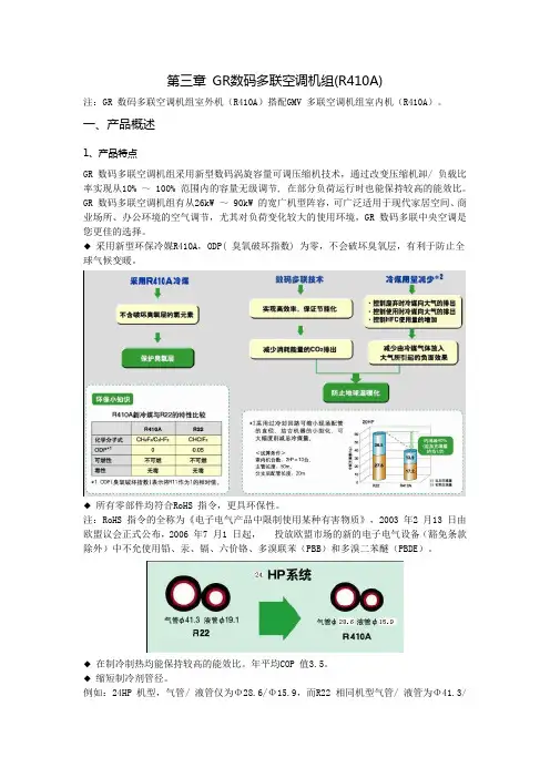
一、产品概述1、产品特点GR 数码多联空调机组采用新型数码涡旋容量可调压缩机技术,通过改变压缩机卸/ 负载比率实现从10% ~ 100% 范围内的容量无级调节, 在部分负荷运行时也能保持较高的能效比。
GR 数码多联空调机组有从26kW ~ 90kW 的宽广机型阵容,可广泛适用于现代家居空间、商业场所、办公环境的空气调节,尤其对负荷变化较大的使用环境,GR 数码多联中央空调是您更佳的选择。
◆采用新型环保冷媒R410A,ODP( 臭氧破坏指数) 为零,不会破坏臭氧层,有利于防止全球气候变暖。
◆所有零部件均符合RoHS 指令,更具环保性。
注:RoHS 指令的全称为《电子电气产品中限制使用某种有害物质》,2003 年2 月13 日由欧盟议会正式公布,2006 年7 月1 日起,投放欧盟市场的新的电子电气设备(豁免条款除外)中不允使用铅、汞、镉、六价铬、多溴联苯(PBB)和多溴二苯醚(PBDE)。
◆在制冷制热均能保持较高的能效比。
年平均COP 值3.5。
◆缩短制冷剂管径。
例如:24HP 机型,气管/ 液管仅为Φ28.6/Φ15.9,而R22 相同机型气管/ 液管为Φ41.3/Φ19.05。
方便配管工作,节省安装空间,节省管材材料费用。
◆智能除霜,更高效制热。
系统高压控制化霜,实现无霜不化。
用高压压力控制化霜的优点是:可以做到“无霜不化”,当在一定工况下,室外空气相对湿度小,基本不结霜,此时机组运行制热效果不受结霜的影响,机组可长时间运行不化霜。
比传统的定时化霜模式节能。
可以延长化霜时间,霜结到一定程度才化,而不是过早化霜或过晚化霜,通过高压值可客观地检测影响室内制热效果的程度。
◆制热范围低至-20℃。
◆长配管设计◆ 5 向接线和配管连接长配管设计冷媒管连接方向二、产品性能与规格1 、产品外形图GMV-R260W2/Na-N2 GMV-R450W3/Na-N1 GMV-R300W2/Na-N2GMV-R560W4/Na-N1 GMV-R860W6/Na-N1GMV-R600W4/Na-N1 GMV-R900W6/Na-N1 2、产品性能参数注:① . 本机组设计执行标准GB/T 18837-2002。
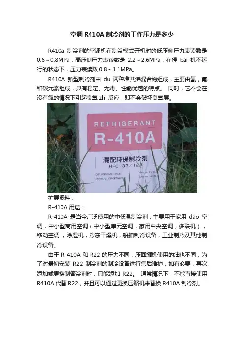
空调R410A制冷剂的工作压力是多少
R410a制冷剂的空调机在制冷模式开机时的低压侧压力表读数是0.6~0.8MPa,高压侧压力表读数是2.2~2.6MPa,在停bai机不运行的状态下,压力表读数0.8~1.1MPa。
R410A新型制冷剂由du两种准共沸混合物组成,主要由氢,氟和碳元素组成,具有稳定、无毒、性能优越的特点。
同时,它不会在没有氯的情况下引起臭氧zhi反应,即不会破坏臭氧层。
扩展资料:
R-410A用途:
R-410A是当今广泛使用的中低温制冷剂,主要用于家用dao空调,中小型商用空调(中小型单元空调,家用中央空调,多联机),移动空调,除湿机,冷冻干燥机,船舶制冷设备,工业制冷及其他制冷设备。
由于R-410A和R22的压力不同,压回缩机使用的油也不同,为了对最初安装R22制冷剂的制冷设备进行售后维护,如有必要,再次添加或更换制答冷剂时,只能添加R22。
通常情况下,不能直接使用R410A代替R22,并且可以通过更换压缩机来替换R410A制冷剂。
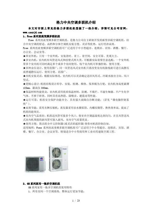
格力中央空调多联机介绍本文对市面上常见的格力多联机机型做了一些介绍。
详情可见公司官网:1、Free系列直流变频多联机组Free系列直流变频多联空调机组,是格力公司自主研制开发的新型多联空调机组,结合中央空调的舒适、高档和分体空调机安装方便、灵活等优势,运行经济高效。
Free系列直流变频多联空调机组可广泛适用于中小型超市、连锁店、宾馆、酒楼、餐厅、办公室、会议室等。
★单室外机:只有一个室外机,安装省时、省工、省空间,安全可靠、美观大方。
★多室内机:室内机有风管送风式和挂壁式两大类,可根据实际需要任意选配;一个室外机带多个室内机可同时满足单个或多个房间使用,每个室内机可单独控制,使用方便。
★多种余压设计,使用范围广:同一风管送风式室内机只需改变室内机接线就可进行高静压或普通静压运行,使用方便、范围广。
★内机安装灵活:根据实际情况,室内机可以灵活确定送回风形式、冷凝水接出方向、风口型式。
★更精心设计:机组结构设计科学,安装、检测、维修、保养极为方便;室内机身高度最薄185mm,最高仅300mm。
★保温材料性能优良:室内机采用优质保温材料,防潮、不腐烂、不滋生细菌、不产生化学气体、不掉下碎屑、同时具有高热阻、隔噪音、避震动等性能。
★运行可靠:机组安全保护功能齐全,具有强大故障自诊断功能;(详见“微电脑控制系统”)。
★高效节能:采用名牌压缩机;蒸发器采用亲水膜铝箔、内螺纹铜管,换热效率高,提高了机组的能效比。
★室内空气品质好:机组送风管可接多个风口,使室内空调温湿度达到均匀,并且风管送风式室内机预留的新风管可接入新风,室内空气质量优良。
★使用方便:简洁的全中文控制器(或灵活的遥控器)使你对机组控制自如。
适用场所:Free系列直流变频多联空调机组可广泛适用于中小型超市、连锁店、宾馆、酒楼、餐厅、办公室、会议室等。
特别适合中小型商用和工业应用建筑空调工程。
2、GH系列家用一拖多空调机组GH系列家用一拖多空调机组使用特性1、所有房间一个空调系统,整体运行更加节能;2、内机可引入新风,提高室内空气品质;3、空调专业人士进行空调设计,优化送回风方式,房间温度均匀,温馨舒适;4、每个房间的空调可以独立控制,满足家庭中中不同使用者的个性要求;5、考虑到不需要同时使用所有房间的空调特性,空调室外机可适当选的偏小,节约初装成本。
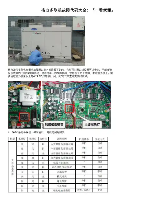
格⼒多联机故障代码⼤全:「⼀看就懂」
格⼒四代多联机有很多故障通过室内机是看不到的,有些可以通过线控器可以查询,不能准确
显⽰故障的⽐如E5故障代码,这不是单⼀的故障代码,它包含了23个故障,都在室外机上。
需要通过室外机主板上的6个LED灯的“亮、闪、灭”⽅式来查询真实的故障。
1、GMV 系列多联机(485 通讯)内机灯闪对照表
以上为四代机的故障代码表,请保存好,四代机都已过保修期,学会了就是赚钱的机会!
记得在⽂章最后留⾔区留⾔哦!感觉有⽤,可以转发给你的朋友,请他们和你⼀块⼉学习,⼀
起成长。
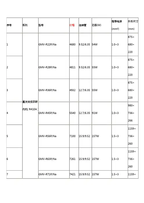
GMV数码多联空调机组本手册适用下列室外机组及其所搭配的室内机:GMV-R600W4/A GMVL-R600W4/AGMV-R500W4/A GMVL-R500W4/AGMV-R400W3/A GMVL-R400W3/AGMV-R300W2/B GMVL-R300W2/BGMV-R250W2/B GMVL-R250W2/BGMV-R200W2/B GMVL-R200W2/B目录一、产品型号表示方式 (3)二、产品特点 (4)三、微电脑控制系统 (5)四、集中控制和远程监控 (6)五、室外机 (8)六、室内机 (11)七、能力修正 (23)八、室内外机组的连接 (28)九、机组接线图 (32)十、电力参数 (34)十一、其它要求 (37)一、产品型号表示方式1. 室内机型号表示方式GMVL—R70P/A:表示名义制冷量为7000W的风管式单冷型多联空调室内机。
2. 室外机型号表示方式型号示例:GMV—R300W2/B:表示有两个压缩机的名义制冷量为30KW的B系列的数码多联热泵型空调室外机。
二、产品特点GMV数码多联空调机组采用新型数码涡旋容量可调压缩机技术,设计安装方便灵活,运行经济高效。
具体特点如下:1. 灵活自由的室内机组成a. 室内机最大总容量可达室外机容量的135%。
室外机容量不同,可连接的室内机台数不同。
一台室外机最多可连接三十二台室内机。
b. 按各个房间的用途和装修特点,可以选用不同型式、不同容量的室内机,使室内装修谐调美观;可以连接的室内机有天井式、挂壁式、暗藏风管式、低静压超薄风管式、座吊两用式及落地式等机型。
2. 先进的PWM容量可调压缩机技术a. GMV系统的容量调节采用新型数码涡旋压缩机技术,通过改变压缩机卸/负载比率实现从10%~100%范围内的容量无级调节。
b. PWM(Pulse-Width Modulation)数码容量调节电磁阀通过压力控制压缩机轨道涡旋盘和固定涡旋盘的离合,从而实现卸/负载的目的。
格力中央空调GMV5室内机参数
特点:
节能——节省运行费用
格力GMV5直流变频多联机采用格力最新的直流变频技术
额定制冷量(CC)单位:KW
能效等级
5级4级3级2级1级
CC≤28 2.80 3.00 3.20 3.40 3.60 28<CC≤84 2.75 2.95 3.15 3.35 3.55
CC>84 2.70 2.90 3.10 3.30 3.50
参考国家《多联式空调(热泵)机组综合性能洗漱限定值及能源效率等级》标准GB2154-2008舒适——冷暖随心掌控
智能——人性化控制
百变——配合装修风格
快捷——节省安装工期
省心——机组可靠稳定
室内机参数
SE系列低静压风管式室内机
SDTS系列高效双面出风天井式室内机
SDH系列高效高静压风管式室内机
ST系列四面出风天井式室内机
SG系列壁挂式室内机
SDTD系列高效单面出风天井式室内机
SDC系列高效静音型风管式室内机。
目录第一章产品篇……………………………………………………………………1 产品种类…………………………………………………………………………………2 产品命名规则……………………………………………………………………………3 产品特点…………………………………………………………………………………4 产品技术参数表…………………………………………………………………………5 产品性能修正……………………………………………………………………………6 产品工作原理……………………………………………………………………………第二章控制篇……………………………………………………………………1 机组控制…………………………………………………………………………………2 控制功能…………………………………………………………………………………第三章安装篇……………………………………………………………………1 安装注意事项……………………………………………………………………………2 安装流程…………………………………………………………………………………3 机组安装要求……………………………………………………………………………4 配管………………………………………………………………………………………5 电气安装…………………………………………………………………………………第四章维修篇……………………………………………………………………1 机组故障一览表…………………………………………………………………………2 典型故障排查……………………………………………………………………………3 案例分析…………………………………………………………………………………4 机组配电…………………………………………………………………………………5 机组部件及拆装…………………………………………………………………………6 爆炸图及零部件清单……………………………………………………………………第一章产品篇1.产品种类1.1 GMV室外机1.2 GMV室内机◆GMV多联室内机组-H系列(R22)2.2kW~4kW 4.5kW~8kW 9kW~14kW普通静压风管机GMV(L)-R22P/HGMV(L)-R25P/HGMV(L)-R28P/HGMV(L)-R32P/HGMV(L)-R36P/HGMV(L)-R40P/HGMV(L)-R45P/HGMV(L)-R50P/HGMV(L)-R56P/HGMV(L)-R63P/HGMV(L)-R71P/HGMV(L)-R80P/HGMV(L)-R90P/H(S)GMV(L)-R100P/H(S)GMV(L)-R112P/H(S)GMV(L)-R125P/H(S)GMV(L)-R140P/H(S)超薄风管机GMV(L)-R22P/HLGMV(L)-R25P/HLGMV(L)-R28P/HLGMV(L)-R32P/HLGMV(L)-R36P/HLGMV(L)-R40P/HLGMV(L)-R45P/ HLGMV(L)-R50P/HLGMV(L)-R56P/HLGMV(L)-R63P/HLGMV(L)-R71P/ HL四面出风天井机GMV(L)-R28T/HGMV(L)-R36T/HGMV(L)-R45T/HGMV(L)-R50T/HGMV(L)-R56T/HGMV(L)-R63T/HGMV(L)-R71T/HGMV(L)-R80T/HGMV(L)-R90T/H(S)GMV(L)-R100T/H(S)GMV(L)-R112T/H(S)GMV(L)-R125T/H(S)单面出风天井机GMV(L)-R22Td/H GMV(L)-R28Td/H GMV(L)-R36Td/H挂壁机GMV(L)-R22G/HGMV(L)-R28G/HGMV(L)-R36G/H挂壁机GMV(L)-R45G/HGMV(L)-R50G/H◆GMV多联室内机组-R410A系列2.产品命名规则2.1 室外机命名规则GMV/W 补充代号型式代号设计序号室外机代号功能特征气候类型制冷量*电源种类补充制冷剂种类产品代号室外机型号含义如下表:标准主型号含义产品 代号气候类型型式代号功能特征制冷量室外机 代号* 补充代号:压缩机(或室外机)数量表示方法GMVT1-省略 T2-低温 气候 T3-高温 气候热泵型 省略 L-单冷型R-数码多联 P-交流变频多联 Re-低温热泵数码多联 Pd-直流变频多联名义制冷量×102 (W )W用数字表示,单压缩机省略;型号示例:GMV -R100W/H :表示名义制冷量为10kW 的H 系列数码多联热泵型空调室外机。