燃油水寒宝产品说明书
- 格式:pptx
- 大小:1.28 MB
- 文档页数:8


The ACS can integrate the Alfa Laval Fuel ConditioningModule (FCM) as well as any other booster system, on new buildings or ships in operation.Features and benefitsC ompliance with new fuel regulations ACS allows theoperators to:▪A chieve easy and full automated fuel changeover p rocedures▪H andle up to 3 different fuels▪P erform direct (HFO to MGO) and intermediate (HFO to MDO to MGO) fuel changeover procedureS afetyACS provides cutting edge control of variation in fuelt emperature and viscosity. This makes possible to achieve safe fuel changeover procedures by avoiding any thermal shock and any drop in fuel viscosity. I ntegration▪S eamless communication between ACS and FCM for automatic and reliable fuel changeover procedures▪F ull compatibility of ACS with any fuel conditioning m odule, even from other suppliersA utomation▪A CS is fully automated and easy to operate▪P ossibillity of full process control from remote panel▪F ull changeover procedure customization by controlling all process parametersV ersatility▪O ptional chiller unit available for the supply of proper cooling media to ACS▪P ossibility to develop ACS tailor made versions on requestKey componentsThe ACS scope of supply includes everything needed, with the exception of pipes and cables, to construct a complete fuel cooling system for newbuildings or to retrofit fuel supply systems on existing vessels.A CS CoolerThe ACS is equipped with a heat exchanger that usesfresh water or seawater as cooling media. The plate heatexchanger cooler type has high corrosion resistance, high efficiency and compact design.M ixing valveThis electrically operated three-way mixing valve regulates fuel temperature by partializing the amount of fuel flowing through the ACS cooler. The stepless flow adjustment allows a sharp temperature control of the light fuel, in order to provide a reliable t emperature ramp and final injection temperature.T emperature transmitterMounted on booster module or near the engine, thet emperature transmitter supplies data about fuelt emperature to the engine to the ACS control unit. C hangeover valvesThe ACS incorporates two main three-way changeover valves positioned at the fuel supply feed inlet and prior to the inlet of the ACS cooler. These are supplied according to the dimensions of the connected pipework. One more three-way changeover valve is available as an option to C ontrol systemACS operation is steered and monitored by a controlpanel, and can be equipped for different levels of remote control:▪ B asic – free contacts (only alarms and readings) ▪ E xtended – free contacts (change over start up andalarms and temperature readings) ▪ M odbus – full remote control through onboarda utoma tion systemM odularized assemblyACS is a compact and skid mounted unit, ready for a space saving installation on any booster system.C hiller unitACS is available with a chiller unit from our partner NOVENCO, with start / s top function integrated in the control panel.1. HFO and MGO day tank2. Three way changeover valve (V1)3. Pump strainers4. Supply pump5. Automatic backflushing filter6. Filter pressure drop switch7. Supply pressure control valve8. Flow transmitter9. Flow transmitter bypass10. Pressure transmitter, supply pump 11. Level switch12. Automatic de-aeration valve 13. Mixing tube14. Circulation pump 15. Heaters16. Pressure transmitter, circ. pump 17. Temperature sensor 18. Viscosity sensor19. Engine pressure control valve 20. Three way changeover valve (V2)21. ACS Cooler22. Three way mixing valve (V3)23. Temperature transmitter (TT2)24. Temperature transmitter (TT3)25. SPV Cooler26. Three way changeover valve (V4) 27. Heating media valve (V6)28. Cooling media valve (V7)Operating principleThe ACS operation is based on temperature adjustable s et p oint and viscosity control operated by FCM viscosity sensor.C hangeover from HFO to MGOTo initiate the switch from HFO to MGO, the system gradually shifts the changeover valve (V1) from HFO position to MGO position and reduces the heatingpower in order to control fuel viscosity. The combination of the valve movement and continuous control of heat-ing power ensures a safe and gradual changeover with-out the risk of thermal shock.Once the programmable set point temperature has been obtained, the ACS shifts the changeover valve (V2) from the heater position to the cooler position and begins to control the fuel temperature during the ramp phase by operating the three-way mixing valve (V3). Continuous control of this three-way mixing valve keep fuel tempera-ture and viscosity stable.C hangeover from MGO to HFOTo initiate the switch from MGO to HFO, the systemg radually shifts the changeover valve (V1) from MGOp osition to HFO position and controls the fuel tempera-ture ramp by operating the three-way mixing valve (V3). When the p rogrammable set point temperature has been obtained, the ACS gradually shifts the changeover valve (V2) from the cooler position to the heater position;the booster controls the temperature ramp until the HFOw orking temperature has been obtained. T hree fuels handlingAs an option, the system can handle 3 different fuels and perform direct (HFO to MGO) and intermediate(HFO to MDO to MGO) fuel changeover procedure. This allows to save money by using the suitable fuel for theHow to contact Alfa LavalContact details for all countries are continually updated on our web site. Please visit to access the information direct.EMD00253EN 1103Alfa Laval reserves the right to change specifications without prior notification.A L F A L A V A L i s a t r a d e m a r k r e g i s t e r e d a n d o w n e d b y A l f a L a v a l C o r p o r a t e AB .technical data ACS Module Cooling media SizeWeight ACS 15 F Fresh water 1200 x 600 x 1800 mm 320 kg ACS 40 F Fresh water 1200 x 600 x 1800 mm 350 kg ACS 60 F Fresh water 1500 x 600 x 1800 mm 400 kg ACS 15 S Seawater 1200 x 600 x 1800 mm 320 kg ACS 40 S Seawater 1200 x 600 x 1800 mm 350 kg ACS 60 S Seawater 1500 x 600x 1800 mm 400 kg ACS 50 C Chilled water 1200 x 600 x 1800 mm 320 kg ACS 140 C Chilled water 1200 x 600 x 1800 mm 350 kg ACS 215 C Chilled water 1500 x 600 x 1800 mm 400 kg ACS 70 G Glycol water 1200 x 600 x 1800 mm 320 kg ACS 185 G Glycol water 1200 x 600 x 1800 mm 350 kg ACS 285 GGlycol water1500 x 600 x 1800 mm400 kgCapacity rangeThe ACS accommodates a wide range of fuel supply requirements up to a cooling capability of 285 kW (when combined to a chiller unit). Larger capacities can be supplied upon request.Position – Three-way valveHFO on the circuit – Engine at 85% MCR HFO on the circuit – Engine at 60% MCR HFO on the circuit – Engine at 30% MCR2468101214V i s c o s i t y (c S t )Time (minutes)024681012141618V i s c o s i t y (c S t )Time (minutes)20406080100120H F O – M G O (%)Time (minutes)020*********120M G O – H F O (%)Time (minutes)102030405060708090100110120130140T e m p e r a t u r e (°C )102030405060708090100110120130140T e m p e r a t u r e (°C )HFO to MGO changeoverMGO to HFO changeoverMain supply voltage 1-phase, 110/230 V Main supply frequency 50 or 60 Hz Max oil pressure 16 bar Max oil temperature 160°C。
NetCol5000-C(030,032) 行级冷冻水智能温控产品用户手册文档版本06发布日期2020-03-16版权所有© 华为技术有限公司2020。
保留一切权利。
非经本公司书面许可,任何单位和个人不得擅自摘抄、复制本文档内容的部分或全部,并不得以任何形式传播。
商标声明和其他华为商标均为华为技术有限公司的商标。
本文档提及的其他所有商标或注册商标,由各自的所有人拥有。
注意您购买的产品、服务或特性等应受华为公司商业合同和条款的约束,本文档中描述的全部或部分产品、服务或特性可能不在您的购买或使用范围之内。
除非合同另有约定,华为公司对本文档内容不做任何明示或默示的声明或保证。
由于产品版本升级或其他原因,本文档内容会不定期进行更新。
除非另有约定,本文档仅作为使用指导,本文档中的所有陈述、信息和建议不构成任何明示或暗示的担保。
华为技术有限公司地址:深圳市龙岗区坂田华为总部办公楼邮编:518129网址:https://前言概述本文档主要介绍简配版NetCol5000-C行级冷冻水智能温控产品(以下简称为:NetCol5000-C)的产品概述、室内机安装、调测、系统运行和维护,方便读者系统的掌握NetCol5000-C的使用和维护。
本文档图片仅供参考,具体请以实物为准。
读者对象本文档主要适用于以下工程师:●行销工程师●技术支持工程师●系统工程师●硬件安装工程师●调测工程师●数据配置工程师●维护工程师符号约定在本文中可能出现下列标志,它们所代表的含义如下。
修订记录修改记录累积了每次文档更新的说明。
最新版本的文档包含以前所有文档版本的更新内容。
文档版本06 (2020-03-16)优化“准备和登录Web”章节。
文档版本05 (2019-12-20)更新安全注意事项。
文档版本04 (2019-06-26)取消自研冷冻水阀。
文档版本03 (2019-03-18)修改温湿度传感器章节。
文档版本02 (2019-01-15)刷新手册名称等。
柴油机水寒宝的工作原理柴油机水寒宝是一种用于冷却柴油机的设备,它的工作原理是通过循环水流来吸收热量,将水寒宝中的冷却水冷却,然后再循环回柴油机冷却系统,以达到冷却柴油机的效果。
下面将详细介绍柴油机水寒宝的工作原理。
柴油机水寒宝的主要组成部分包括水寒宝本体、冷却水泵、风扇马达、传动装置、水箱和冷却水管路等。
当柴油机启动时,冷却水泵开始工作,它会将水从水箱中抽取出来,并通过冷却水管路输送到柴油机水冷却系统中。
柴油机水冷却系统包括发动机头部、缸体、气缸盖等部位,它们通过水冷却系统与水寒宝相连接。
冷却水进入水寒宝后,会经过水寒宝的散热芯子,散热芯子是由许多铜管组成的,通过这些铜管散热芯子与空气进行热交换。
风扇马达启动时,会通过传动装置带动风扇转动,从而加速空气流过散热芯子,增加散热效果。
在热交换过程中,散热芯子中的冷却水吸收柴油机释放的热量,将水温降低。
然后,冷却水通过冷却水管路返回发动机冷却系统,继续对发动机进行冷却。
冷却水在循环中可以多次与冷却系统接触,不断吸收并带走热量,保持柴油机的正常工作温度。
同时,水寒宝还可以根据柴油机的工作负荷进行智能调节。
当柴油机负荷较轻时,水寒宝会自动减小散热芯子的冷却风扇转速,减少冷却水的循环量,以减少能耗。
当柴油机负荷较重时,水寒宝会自动增加风扇转速,增加冷却水的循环量,以加强冷却效果,确保柴油机工作正常。
另外,水寒宝还具有一些保护功能。
例如,当柴油机水冷却系统中的水温过高时,水寒宝会发出警报并停止供水,以避免发动机过热。
当冷却水压力过高或过低时,水寒宝也会发出警报并停止供水,以保护冷却系统的安全运行。
总结起来,柴油机水寒宝的工作原理是通过水流循环来冷却柴油机。
冷却水从水箱中抽取出来,经过散热芯子与空气进行热交换,吸收柴油机释放的热量,然后再循环返回发动机冷却系统。
水寒宝还具有智能调节和保护功能,以确保柴油机的正常工作温度和安全运行。

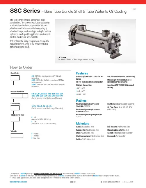
FeaturesInterchangeable with TTP C and HC SeriesAll 316 Stainless Steel construction Multiple Connections ▪ NPT x NPT ▪ SAE x NPT ▪ BSPP x BSPEnd Bonnets removable for servicing Mounting feet included (May be rotated in 90° increments)Special ASME/TEMAC/CRN consult factorySSC Series – Bare Tube Bundle Shell & Tube Water to Oil CoolingMaterialsTubes 316 Stainless steelTubesheets 316L Stainless steel Shell 316L Stainless steelShell Connections 316L Stainless steel Baff l es 316 Stainless steelEnd Bonnets 316 Stainless steel Mounting Brackets Mild steel Gaskets Nitrile rubber/cellulose fiber Nameplate Aluminum foilRatingsMaximum Operating Pressure - Shell Side 300 PSI*Maximum Operating Pressure - Tube Side 150 PSIMaximum Operating Temperature 300°FHeat Removal Up to 350 HP (260 KW)Oil Flow Rates Up to 160 U.S. GPM (350 L/MIN)0223The SSC Series features all stainless steelconstruction. The proven fixed tubesheet design shell and tube heat exchanger offers the cost effectiveness that comes with having a highly standard design, while easily providing for various options to meet specific application requirements. Custom models are also available.TTP’s XSelector sizing program can be used to help optimize the sizing of the cooler for better performance and value.*To register for X Selector please go to /get-in-touch/ and complete the X Selector Inquiry form and submit.Download the X Selector for both Apple and Android formats by searching for X Selector in their App Stores. You must first register for X Selector before using it on mobile devices.** For Salt Water applications a Zinc Anode needs to be plumbed in the water inlet of the cooler to prevent corrosion.Model SeriesModel Size SelectedTube Diameter CodeTubesideBaffle SpacingSSC - NPT Shell side connections x NPT Tube side connectionsSSCS - SAE O-Ring Shell side connections x NPT Tube side connectionsSSCM - BSPP Shell side connections x BSPP Tube side connections614, 624, 814, 824, 836, 1014, 1024, 1036, 1224, 1236, 1248, 1260, 1724, 1736, 1748, 1760, 1772(See Performance Curve Chart on page 3 for sizes)1.3, 1.7, 2,2.5, 3,3.5, 4, 5, 6, 8.4(See Performance Curve Chart on page 3 for options)4 - 1/4”(standard for 600 & 800 Series)6 - 3/8”(standard for 1000, 1200 & 1700 Series)0 - One Pass T - Two Pass F - Four PassHow to OrderOPTIONSFor ASME/TEMAC/CRN ratings consult factorySelection ProcedureSSC-1014-2-6-*33 GPM Max.SSC-1014-5-6-*66 GPM Max.SSC-1724-3.5-6-*105 GPM Max.SSC-1724-8.4-6-*200 GPM Max.Caution: Incorrect installation can cause this product to fail prematurely, causing the shell side and tube side fluids to intermix.Specific applications may have different piping arrangements. Contact factory for assistance.Piping DiagramPerformance Curves are based on 100SSU oil leaving the cooler 40°F higher than the incoming water temperature (40°F approach temperature). Curves are based on a 2:1 oil to water ratio.STEP 1D etermine the Heat Load. This will vary with different systems, but typically coolers are sized to remove 25 to 50% of the input nameplate horsepower. (Example: 100 HP Power Unit x .33 = 33 HP Heat load.)If BTU/HR is known: HP = BTU/HR 2545STEP 2Determine Approach Temperature. Desired oil leaving cooler °F – Water Inlet temp. °F = ActualApproachSTEP 3Determine Curve Horsepower Heat Load. Enter the information from above:HP heat load x 40 x Viscosity = Curve Actual Approach Correction A Horsepower STEP 4 Enter curves at oil flow through cooler and curve horsepower. Any curve above the intersecting point will work.STEP 5Determine Oil Pressure Drop from Curves. Multiply pressure drop from curve by correction factor B found on oil viscosity correction curve.l = 5 PSI n = 10 PSI ▲ = 20 PSIOil TemperatureOil coolers can be selected by using entering or leaving oil tempertures.Typical operating temperature ranges are: Hydraulic Motor Oil 110°F - 130°F Hydrostatic Drive Oil 130°F - 180°F Lube Oil Circuits 110°F - 130°F Automatic Transmission Fluid 200°F - 300°FDesired Reservoir TemperatureReturn Line Cooling: Desired temperature is the oil temperature leaving the cooler. This will be the same temperature that will be found in the reservoir.Off-Line Recirculation Cooling Loop: Desired temperature is the temperature entering the cooler. In this case, the oil temperature change must be determined so that the actual oil leaving temperature can be found. Calculate the oil temperature change (Oil #T) with this formula:Oil #T=(BTUs/HR)/GPM Oil Flow x 210).To calculate the oil leaving temperature from the cooler, use this formula:Oil Leaving Temperature = Oil Entering Temperature - Oil #T.This formula may also be used in any application where the only temperature available is the entering oil temperature.Oil Pressure Drop: Most systems can tolerate a pressure drop through the heat exchanger of 20 to 30 PSI. Excessive pressure drop should be avoided. Care should be taken to limit pressure drop to 5 PSI or less for case drain applications where high back pressure may damage the pump shaft seals.5432.521.51.8.7.6.550607080100150200250300400500ABOil Viscosity - SSUV i s c o s i t y C o r r e c t i o nExample Model No.Maximum Flow RatesOne PassTwo and Four PassCOOLING WATERCOOLING WATERViscosity CorrectionPerformance CurvesOil Flow (GPM)H o r s e p o w e r R e m o v e d i n C o o l erS hipping weights are approximate.For additional sizing information consider using TTP’s X Selector online sizing Program.**To register for X Selector please go to /get-in-touch/ and complete the X Selector Inquiry form and submit.Download the X Selector for both Apple and Android formats by searching for X Selector in their App Stores. You must first register for X Selector before using it on mobile devices.** For Salt Water applications a Zinc Anode needs to be plumbed in the water inlet of the cooler to prevent corrosion.One PassGGHHZ (4 places)(both ends)NOTE: We reserve the right to make reasonable design changes without notice. Consult factory. All dimensions are inches.All models exceptSSC-600SSC-600For 3D models and spec sheets visit the SSC product page on our website.https:///product/ssc-seriesSSC-600SSC-1000SSC-1700SSC-800SSC-1200NOTE: We reserve the right to make reasonable design changes without notice. Consult factory. All dimensions are inches.For 3D models and spec sheets visit the SSC product page on our website.https:///product/ssc-seriesFour PassHHoptionNOTE: We reserve the right to make reasonable design changes without notice. Consult factory. All dimensions are inches.All models exceptSSC-1700SSC-1700For 3D models and spec sheets visit the SSC product page on our website.https:///product/ssc-series。


TO REDUCE THE RISK OF FIRE, ELECTRIC SHOCK, OR INJURY TO PERSONS, OBSERVE THE FOLLOWING:e this unit only in the manner intended by the manufac-turer. If you have questions, contact the manufacturer at the address or telephone number listed in the warranty.2.Before servicing or cleaning unit, switch power off at service panel and lock the service disconnecting means to prevent power from being switched on accidentally. When the service disconnecting means cannot be locked, securely fasten a prominent warning device, such as a tag, to the service panel.3.Installation work and electrical wiring must be done by a quali-fied person(s) in accordance with all applicable codes and standards, including fire-rated construction codes and stan-dards.4.Sufficient air is needed for proper combustion and exhausting of gases through the flue (chimney) of fuel burning equipment to prevent backdrafting. Follow the heating equipment manufacturer’s guideline and safety standards such as those published by the National Fire Protection Association (NFPA),and the American Society for Heating, Refrigeration and Air Conditioning Engineers (ASHRAE), and the local code authori-ties.5.When cutting or drilling into wall or ceiling, do not damage electrical wiring and other hidden utilities.6.To reduce the risk of fire or electric shock, do not use this range hood with an additional speed control device.7.Ducted fans must always be vented to the outdoors.8.To reduce the risk of fire, use only metal ductwork.e with approved cord-connection kit only.10. This unit must be grounded.TO REDUCE THE RISK OF A RANGE TOP GREASE FIRE:1.Never leave surface units unattended at high settings.Boilovers cause smoking and greasy spillovers that may ig-nite. Heat oils slowly on low or medium settings.2.Always turn hood ON when cooking at high heat or when cooking flaming foods.3.Clean ventilating fans frequently. Grease should not be al-lowed to accumulate on fan or filter.e proper pan size. Always use cookware appropriate for the size of the surface element.F30WV SERIESHOODSF24WR & F30WR SERIES HOODSECONOMY RANGE HOODINSTALLATION INSTRUCTIONSTO REDUCE THE RISK OF INJURY TO PERSONS IN THE EVENT OF A RANGE TOP GREASE FIRE, OBSERVE THE FOLLOWING:*1.SMOTHER FLAMES with a close-fitting lid, cookie sheet, or metal tray, then turn off the burner. BE CAREFUL TO PRE-VENT BURNS. If the flames do not go out immediately,EVACUATE AND CALL THE FIRE DEPARTMENT.2.NEVER PICK UP A FLAMING PAN - You may be burned.3.DO NOT USE WATER, including wet dishcloths or towels - a violent steam explosion will result.e an extinguisher ONLY if:A.You know you have a Class ABC extinguisher and you al-ready know how to operate it.B.The fire is small and contained in the area where it started.C.The fire department is being called.D.You can fight the fire with your back to an exit.* Based on “Kitchen Fire Safety Tips” published by NFPA.1.For general ventilating use only. Do not use to exhaust hazardous or explosive materials and vapors.2.To avoid motor bearing damage and noisy and/or unbalanced impellers, keep drywall spray, construction dust, etc. off power unit.3.For best capture of cooking impurities, your range hood should be mounted 18-24" above the cooking surface.4.Please read specification label on product for further information and requirements.INSTALLER: Leave This Manual With Homeowner.!INTENDED FOR DOMESTIC COOKING ONLY !6" ROUND DUCTWALL CAPWALL CAP3-1/4" X 10" DUCTROOF CAP3-1/4" X 10" DUCTADJUSTABLE ELBOWWALL CAPTOOLS ANDMATERIALS REQUIRED❏Drill, electric or ratchet drive ❏1/8" Drill bit for drilling pilot holes❏1-1/4" wood bit for drilling electrical wiring access hole ❏One straight blade and one phillips head screwdriver ❏Pliers❏Pencil and ruler and/or tape measure❏Saber saw or keyhole saw for cutting 1" x 2" wood strips tolength and cutting wall or cabinet openings ❏Caulking, metal snips, duct tape, duct (with elbows and tran-sition, if necessary) and roof or wall cap, as required ❏Electrical wiring and supplies of type to comply with localcodes The following materials are required only for installations on recessed bottom kitchen cabinets:❏Two 1" x 2" x 12" (approximate length) wood strips (pur-chase locally)❏Four 1-1/4" long flat head wood screws (purchase locally)PLANNING DUCTWORK INSTALLATION(This section for F30WV hoods only. F30WR and F24WRhoods skip this section and go on to “Prepare the Hood”.)Begin planning ductwork by deciding where the duct will run between the range hood and the outside. For best performance,use the shortest possible duct run and a minimum number of elbows. There are several choices shown - FIGS. A - F below.FIG. A. Ducting directly through the wall (for range hoods mounted on an exterior wall). Shown are two ways to duct through an outside wall. If a wall cap is used directly off the back of the hood, special care must be taken to make sure that the damper in the damper/duct connector on the hood and damper in the wall cap do not interfere with each other when the hood is operating. This could result in either inadequate air delivery or backdrafts. If this condition does exist, remove the hood damper flap. Sometimes when using a wall cap it is easier to duct vertically and then use an elbow as shown in FIG. B.In more complex ducting situations, a 3-1/4" x 10" rec-tangular ducting range hood (F30WV hood) can be converted to a round duct by means of a transition.FIG. C. Ducting straight up through the roof using 3-1/4" x 10" rectangular duct (for single story installations -F30WV hood only).FIG. D. Ducting between the ceiling joists (for multi-story instal-lations) or through the soffit space above the cabinets (where the soffit connects to an outside wall).FIG. E. Straight up through the roof using 6" round duct (for single-story installations).3-1/4" X 10" TO 6"ROUND DUCT TRANSITIONFIG. E6" ROUND DUCTROOF CAP3-1/4" X 10" TO 6"ROUND DUCT TRANSITIONDAMPER/DUCT CONNECTOR (F30WV HOOD ONLY)HINGEPINSDUCTKNOCKOUTS PREPARE THE HOOD1.Unpack hood and check contents. You should receive:1 -Aluminum Filter (F30WV hood only)1 -3-1/4" x 10" Damper/Duct Connector (mountedinside of hood for shipping only) (F30WVhood only)1 - Ductree filter (F24WR and F30WR hoods only)2.Remove wiring box cover. Under cover find:1 -Plastic Bag containing loose mounting hard-ware3.Remove top or rear electrical knockout. (FIG. 2)4.(F30WV hood ONLY) Remove duct knockout. Insert screw-driver under edge of knockout, break tabs, and peel knock-out back with pliers. (FIG. 3)5.(F30WV hood ONLY) Install damper/duct connector overopening made in STEP 4. Use #8B sheet metal screws pro-vided. (FIG. 3)WIRING BOX COVERDUCTFREEFILTER(F24WR &F30WRHOODONLY)ALUMINUMFILTER(F30WVKEYHOLESLOTSPREPARE THEINSTALLATION LOCATIONOmit STEP 1 if hood will be installed under cabinets with flushbottom.1.(For installation on recessed bottom cabinets only) Attach awood filler strip at each side of recessed area under cabi-net. Use two 1" x 2" strips cut to length. If recess is deeperthan 1" use thicker strips. Attach strips with 1-1/4" woodscrews, 3" from each end of strip. See FIG. 4.2.Measure and mark the following (FIGS. 5A & 5B):a.) Electrical wiring opening in wall or cabinet.e 1-1/4" bit to drill opening for electric wiring.4.Cut out duct opening in wall or cabinet with saber saw orkeyhole saw.5.Center hood in installation opening and trace keyhole slotsonto wood filler strips on cabinet bottom.6.Screw four #10 x 7/8 wood screws into exact center of narrowend of traced keyhole slots. Allow 3/8" of screws to project, sothat hood can be fitted into place later.ELECTRICALKNOCKOUTSFIG. 5ACENTER LINEFILLER STRIP**10-15/16" FOR 24" RANGE HOOD, 13-15/16" FOR 30" RANGE HOOD FIG. 6FIG. 7FIG. 8SOFFITFIG. 5BF24WR,F30WR & F30WV1.Run electric wiring through hole drilled in wall or cabinet. Split wir-ing for 6" and install proper connector for type of wire used. (FIG. 9)2.Position hood so that:a.)Wiring is routed through knockout opening (FIG. 10)b.)Large part of keyhole slots fit over hood mounting screws.(FIG. 10)c.)Damper/duct connector slides into ductwork.(F30WV hoods only)3.Adjust hood so that hood front is flush with cabinet frame.4.Tighten hood mounting screws firmly.5.Fasten wiring to hood with proper electrical connector for type of6.Strip 1/2" of insulation from wires. Connect white to white, black to black, and green to prepared hole with green ground screw pro-vided. (FIG. 11)7.Replace wiring box cover and screw. Make sure that all wiring is safely contained inside.8.Install light (75 Watt maximum). For easier installation, squeeze plas-tic lens and remove it from hood. Remember to reinstall lens. (FIG.12)9.Turn on power and check operation of fan and light. Make sure that damper operates freely.KEYHOLE SLOT OUTLINECENTER LINEFILLER STRIPSWALL CAPCABINETROOF CAPDUCTSOFFITCABINETINSTALL THE DUCTWORK(This section for F30WV hoods only. F24WR and F30WR hoods HOOD WIDTHCONNECTORSOCKET LIGHT LENSFAN ASSEMBLYRemove filter. Remove two screws holding motor bracket to range hood, and unplug fan assembly. Be careful not to allow fan assembly to drop when screws are removed. (FIG. 14)CLEANINGClean your hood with a mild detergent suitable for painted sur-faces. DO NOT USE ABRASIVE CLOTH, STEEL WOOL PADS OR SCOURING POWDERS.Fan assembly may be vacuumed. Fan assembly is permanently lubricated, and never needs oiling.HOW TO AVOID A COMMON RANGE-TOP GREASE FIRE •Your range hood provides a protective barrier between the cooking surface and the cabinets.•Keep fan, filters and grease laden surfaces CLEAN ac-cording to instructions.•Always turn hood ON when cooking at high heat to keep the cooking area and the hood cooler.•Use high heat settings only when necessary.•Never leave cooking surface unattended. Boil-over causes smoking and greasy spillovers that may ignite.•Always use adequate-sized utensils.•If preparing flaming foods, such as Cherries Jubilee, always turn hood ON to HIGH to prevent a high heat situation which can cause damage or fire.HOW TO EXTINGUISH A COMMON RANGE-TOP GREASE FIRE•Never pick up a flaming pan. If dropped, flames can spread quickly.•DO NOT USE WATER! A violent steam explosion may result. Wet dishcloths or towels are also dangerous.•Smother flames with a close fitting lid, cookie sheet or metal tray.•Flaming grease can also be extinguished with baking soda or a multi-purpose dry chemical extinguisher.•Turn off surface units - if you can do so without gettingBLACKWIRES GREEN GROUND SCREWGROUND WIRE (BARE ORGREEN WIRE)GROUNDINGBRACKETSTARLOCKNUTWHITE WIRESUSE AND CARESWITCHESThe fan and light are each controlled by a rocker switch. Thelight switch has two positions, “ON” and “OFF”. The fan switchhas three positions - “HIGH”, “LOW” and “OFF”. ( “OFF” is themiddle position.)FILTERSF30WV Hood Only:Remove aluminum filter by turning filter retainer to one side.(FIG. 13) Filter should be washed once a month in a hot deter-gent solution. Aluminum filters are dishwasher safe. When in-stalling filter, make sure that filter slides under retaining tabs onback of fan housing. Turn filter retainer so that arrows on re-tainer point toward front and back of hood.F24WR & F30WR Hoods Only:The F24WR AND F30WR hoods are equipped with a ductfreefilter. Remove filter by turning filter retainer to one side. (FIG. 13)The ductfree filter is not washable, and will last up to twelve monthswith normal use. Replace the filter when colored side becomesnoticeably dirty or discolored.When installing filter, make sure that filter slides under retain-ing tabs on back of fan housing. MAKE SURE THAT COLOREDSIDE OF FILTER IS NEXT TO FAN WHEN FILTER IS IN-STALLED. Turn filter retainer so that arrows on retainer pointtoward front and back of hood.FILTERFILTER RETAINERTABSSCREWSSERVICE PARTSF30WV SERIES 3-1/4" X 10"DUCTED HOODKEY NO.DESCRIPTION1Outlet Box Cover2#8 x 3/8 Sheet Metal Screw* 3Bulb Holder with Wires 4Light Lens5Screw/Nut Kit (Includes 2 - #10-16 x .500screws and 2 - #10-16 sheet metal nuts) 6Fan Blade7#6-32 Locking Nuts* (2 Required) 8Motor Mounting Bracket9Motor Assembly (Includes Key Nos. 6, 7, & 8)10Aluminum Filter 11Filter Retainer12#8B x 1/4 Hex Head Sheet Metal Screws*(2 Required)13Damper Flap 14Damper Bushing 15Damper Assembly(Includes Key Nos. 13, 14 and 21)16Nameplate - Black Nameplate - White172-Speed Motor Switch - Black 2-Speed Motor Switch - White 18Light Switch - Black Light Switch - White19Motor Receptacle with Wires20#10-32 x 1/2 Green Ground Screw*21Damper Bumper**Light Bulb, 75 Watt (not included)*Order service parts by "KEY NO."* Standard Hardware. May be purchased locally.** Not Illustrated.21SERVICE PARTSF30WR & F24WR SERIESNON-DUCTED HOODKEY NO.DESCRIPTION1Outlet Box Cover2#8 x 3/8 Sheet Metal Screw*3Bulb Holder with Wires4Light Lens5Screw/Nut Kit (Includes 2 - #10-16 x .500screws and 2 - #10-16 sheet metal nuts)6Fan Blade7#6-32 Locking Nuts* (2 Required)8Motor Mounting Bracket9Motor Assembly(Includes Key Nos. 6, 7, & 8)10Ductfree Filter11Filter Retainer12Nameplate - Black17 Nameplate - WhiteNameplate - Bisque132-Speed Motor Switch - Black2-Speed Motor Switch - White2-Speed Motor Switch - Bisque14Light Switch - BlackLight Switch - WhiteLight Switch - Bisque15Motor Receptacle with Wires16#10-32 x 1/2 Green Ground Screw*17Grommet**Light Bulb, 75 Watt (not included)*Order service parts by "KEY NO."* Standard Hardware. May be purchased locally.** Not Illustrated.This warranty does not cover the following:1.Products with original serial numbers that have been removed, altered or cannot be readily determined.2. Product that has been transferred from its original owner to another party or removed outside the USA orCanada.3. Rust on the interior or exterior of the unit.4. Products purchased "as-is" are not covered by this warranty.5. Food loss due to any refrigerator or freezer failures.6.Products used in a commercial setting.7. Service calls which do not involve malfunction or defects in materials or workmanship, or for appliancesnot in ordinary household use or used other than in accordance with the provided instructions.8. Service calls to correct the installation of your appliance or to instruct you how to use your appliance.9. Expenses for making the appliance accessible for servicing, such as removal of trim, cupboards, shelves, etc.,which are not a part of the appliance when it is shipped from the factory. 10.Service calls to repair or replace appliance light bulbs, air filters, water filters, other consumables, or knobs,handles, or other cosmetic parts.11.Surcharges including, but not limited to, any after hour, weekend, or holiday service calls, tolls, ferry tripcharges, or mileage expense for service calls to remote areas, including the state of Alaska.12. Damages to the finish of appliance or home incurred during installation, including but not limited to floors,cabinets, walls, etc.13.Damages caused by: services performed by unauthorized service companies; use of parts other than genuineElectrolux parts or parts obtained from persons other than authorized service companies; or external causes such as abuse, misuse, inadequate power supply, accidents, fires, or acts of God.DISCLAIMER OF IMPLIED WARRANTIES; LIMITATION OF REMEDIESCUSTOMER'S SOLE AND EXCLUSIVE REMEDY UNDER THIS LIMITED WARRANTY SHALL BE PRODUCT REPAIR OR REPLACEMENT AS PROVIDED HEREIN. CLAIMS BASED ON IMPLIED WARRANTIES, INCLUDING WARRANTIES OF MERCHANTABILITY OR FITNESS FOR A PARTICULAR PURPOSE, ARE LIMITED TO ONE YEAR OR THE SHORTEST PERIOD ALLOWED BY LAW, BUT NOT LESS THAN ONE YEAR. ELECTROLUX SHALL NOT BE LIABLE FOR CONSEQUENTIAL OR INCIDENTAL DAMAGES SUCH AS PROPERTY DAMAGE AND INCIDENTAL EXPENSES RESULTING FROM ANY BREACH OF THIS WRITTEN LIMITED WARRANTY OR ANY IMPLIED WARRANTY . SOME STATES AND PROVINCES DO NOT ALLOW THE EXCLUSION OR LIMITATION OF INCIDENTAL OR CONSEQUENTIAL DAMAGES, OR LIMITATIONS ON THE DURATION OF IMPLIED WARRANTIES, SO THESE LIMITATIONS OR EXCLUSIONS MAY NOT APPLY TO YOU. THIS WRITTEN WARRANTY GIVES YOU SPECIFIC LEGAL RIGHTS. YOU MAY ALSO HAVE OTHER RIGHTS THAT VARY FROM STATE TO STATE.Keep your receipt, delivery slip, or some other appropriate payment record to establish the warranty period should service be required. If service is performed, it is in your best interest to obtain and keep all receipts.Service under this warranty must be obtained by contacting Electrolux at the addresses or phone numbers below.Your appliance is covered by a one year limited warranty . For one year from your original date of purchase,Electrolux will pay all costs for repairing or replacing any parts of this appliance that prove to be defective in materials or workmanship when such appliance is installed, used, and maintained in accordance with the provided instructions.This warranty only applies in the USA and Canada. In the USA, your appliance is warranted by Electrolux Major Appliances North America, a division of Electrolux Home Products, Inc. In Canada, your appliance is warranted by Electrolux Canada Corp. Electrolux authorizes no person to change or add to any obligations under this warranty. Obligations for service and parts under this warranty must be performed by Electrolux or an authorized service company. Product features or specifications as described or illustrated are subject to change without notice.USA1.800.944.9044Electrolux Major Appliances North America P .O. Box 212378 Augusta, GA 30907Canada1.800.668.4606Electrolux Canada Corp.5855 Terry Fox WayMississauga, Ontario, CanadaL5V 3E4ExclusionsIf You Need Service。


潍柴动力的燃油水寒宝潍柴动力的燃油水寒宝目前是潍柴的主流柴油发动机的四大配置之一。
在十一五期间,潍柴集团累计开发新产品达37项,在国内率先成功研发了满足欧Ⅲ、欧Ⅳ和欧Ⅴ排放标准的拥有完全自主知识产权的大功率高速柴油机。
2010年9月,潍柴把被各卡车企业誉为黄金排量的发动机蓝擎动力进行了升级,“蓝擎动力Ⅱ代”撼动上市。
潍柴动力蓝擎产品线在2011年全面切换至蓝擎动力Ⅱ代。
水寒宝是蓝擎动力Ⅱ代的主要配置之一。
截止2011年6月,潍柴已经实现月产发动机10万台的能力,主要技术指标与国际先进水平接轨,新产品产值占总产值的比例已由45%上升到目前的58%,即58%的产品是蓝擎动力Ⅱ代柴油发动机。
燃油水寒宝目前在潍柴的多种发动机上安装,我统计有WP4,WP5、WP6、WP7“心动力”系列柴油机WP13系列国Ⅳ柴油机WP12系列国Ⅲ/Ⅳ柴油机WP10N系国Ⅲ/Ⅳ共轨柴油机WP10国ⅢEGR系列柴油机WP7系列国Ⅲ/Ⅳ柴油机WD6/WD10/WD12国Ⅲ/Ⅳ系列柴油机适用汽车有矿用卡车、混凝土搅拌车、压路机、推土机、蓝擎二代装载机,挖掘机、各种工程机械车等,实际情况是所有采用电控高压共轨柴油发动机的重卡和工程车,全部要使用水寒宝。
燃油水寒宝提高发动机可靠性解决高寒地区出现的因燃油结蜡致使发动机难以起动,或起动后又熄火的问题解决整车下线时、整车保养后,使用起动机拖动排气导致起动机、齿圈故障率高的问题解决人工排气引起用户抱怨使用高于环境温度的高标号燃油,降低使用成本使用“水寒宝”的发动机,在零下-10环境下,使用0柴油,柴油机能正常工作;燃油水寒宝-007的四个功能燃油电加热电动燃油泵过滤燃油中介质(我们的CLQ92-2000除水放心滤)过滤燃油中水分(我们的CLQ92-1020除水沉淀杯)燃油水寒宝-007 四个功能支持蓝擎动力七项改善:1、启动性能提升2、降低启动机的故障率3、降低齿圈的故障率4、降低燃油泵的故障率5、降低喷油器的故障率6、降低对燃油标号的要求,降低了燃油成本7、油耗低(0#柴油比-10#柴油燃烧效率高)燃油水寒宝-007的结构特点:燃油水寒宝-007的安装要求:总之,潍柴燃油水寒宝是潍柴动力的主要柴油发动机的主要配置之一,需求量预计为50000台/月以上。
丰田燃油干燥除水剂的用法
丰田燃油干燥除水剂是用于去除汽车燃油中的水分的产品。
以下是使用该产品的步骤:
1. 确保你已经购买了适合丰田汽车的燃油干燥除水剂,并阅读了产品说明和安全提示。
2. 停车并关闭发动机。
找到汽车的燃油箱盖,打开它。
3. 使用一个干净的布或纸巾,擦拭燃油箱盖周围的区域,以确保没有灰尘或其他杂质进入燃油箱。
4. 打开燃油箱盖,并使用丰田燃油干燥除水剂的注射器或喷雾器将产品缓慢地倒入燃油箱内。
请根据产品说明书上的推荐用量进行操作。
5. 关闭燃油箱盖,并确保密封好。
6. 启动汽车的发动机,并让其运行一段时间,以使燃油与燃油干燥除水剂混合。
最好在高速行驶时进行这个操作。
7. 运行一段时间后,可以将汽车停下来,再次关闭发动机。
8. 检查燃油箱盖周围是否有任何泄漏。
如果发现任何问题,请及时清洁和修复。
请注意,在使用丰田燃油干燥除水剂之前,建议阅读产品说明书并按照其指示操作。
如果你对汽车维护不确定或不熟悉,最好咨询专业技术人员的建议和帮助。
GWO Water/oil cooler Lightweight, compact and efficient for industrial and marine applicationsThe Olaer Group is part of Parker Hannifin since July 1st, 2012. With manufacturing and sales in 14 countries in North America, Asia and Europe, the Olaer Group expands Parker’s presence in geographic growth areas and offers expertise in hydraulic accumulator and cooling systems for target growth markets such as oil and gas, power generation and renewable energy.Gasketed water/oil coolersThe Parker GWO water/oil cooler is built on a modular concept designed to provide maximum efficiency in transferring heat from one liquid to another.Frames, plates and connections can be combined to form a num-ber of different water/oil coolers.By using different types of plates, with different characteristics, the water/oil coolers can be adapted to a wide variety of applications. The GWO cooler can easily be expanded or adapted by adding or replacing plates whenever conditions change.GWO water/oil coolers in short:• Light and compact • Suitable for many applications • Easy installation • Cost-efficient andenvironmentally friendlyRemovable CoverCarrying BarGuide BarFixed CoverPlate PackRoller AssemblyGasketSpecifications may be changed without prior notice. Please contact Parker for specific details.GC and GL PlatesSymmetrical plates for regular use. Different plate patterns al-low for optimisation of thermal transfer or pressure drop. An obtuse angle (high-theta plate) gives high resistance and an acute angle (low-theta plate) gives low pressure drop.GX Ultraflex PlatesThe plates are available with a herringbone pattern and either an acute or obtuse angle, making it possible to achieve six channel combinations.Ultraflex allows asymmetrical designs, with the primary and secondary circuits designed for heat transfer efficiency.Medium-theta, same directionHigh-theta,different directionsHigh-theta,same directionLow-theta,same directionMedium-theta, different directionsLow-theta,differentdirections The Ultraflex design allows two plates to be turned and rotated,giving six combinations of high-, and low-theta plate pairs, matching the performance parameters of your application.Gasket selectionGlued GasketsOlaer plate gaskets are made from specially moulded elasto-mers to assure superior per-formance. Numerous gasketmaterials – NBR, FKM and others – are available to match your process conditions, up to oper- ating temperatures of 180 °C.Clip-On GasketsConsider the Clip-On glueless gasket system wherever regular cleaning is necessary, or where aggressive fluids shorten gasket life. The unique design allows for easy and fast clip-on installation for secure sealing and simple removal.The Clip-On is available in NBR. These precision gaskets are moulded under rigorous manufacturing controls and are peroxide-cured for long life and excellent compression setresistance.Gaskets on all other plates are located in tapered grooves.Gaskets on GX Series plates arelocated in the neutral axis.Clip-On gaskets seat and lock-in without tools for trouble-free plate pack assembly and installation.a problem. Every programmeto establish the condition andthorized service, you are guar-anteed to get the most suitable gaskets and plates complete with our Original Equipment Manu-facture Guarantee.Efficient operation is the key to optimum return on investment. Malfunctions and changes in heat transfer can have severe consequences on operational costs and may affect product quality.Dirt, scale and other deposits will reduce the efficiency of your GWO cooler. If contamination is ignored and persists, the plates can be damaged. This in turn could lead to leaks, faulty oper-ation and reduced service lifeof the water/oil cooler. Clogged GWOs can cause damage to upstream and downstream equipment with expensive, unscheduled downtime for repairs.Keep control of your water/oil coolersPollution increases the pressure drop and your energy costs. It can also damage the plates or the gaskets.Crystallisation of fluids when they get in contact with oxygen can deform and damage the plates.oil cooler.DirtGL-008 GX-007GC-009GD-009GL-013GC-016GD-013GX-026GC-026GD-026GX-042GC-044GD-042GX-051GC-051GC-054Plate materials:• AISI 304 / EN 1.4301• AISI 316 / EN 1.4401• Titanium Grade 1• 254 SMO Gaskets:• Nitrile • FKMMax. working pressure:• NI/N 10 bar • PI/P 16 bar • S 25 bar Max working temp:• Nitrile 140 °C • FKM 180 °CApprovals:PED 97/23/EC1. PLATE SySTEM Ultraflex= GX Standard (neutral plane) = GL Standard (bottom plane) = GC Double wall = GD2. FLOW Diagonal flow = D Parallel flow= P 3. COOLEr SIzE (051 is approx. 0.51 m 2)4. CHANNEL TyPE High-theta plates = H Low-theta plates = L Mix of high- and = Mlow-theta plates5. PLATE THICKNESS 0.4 mm = 40.5 mm = 50.6 mm = 60.7 mm= 76. TyPE OF FrAME 10 bar = N 16 bar = P 25 bar= S7. NuMbEr OF PLATES Plate package consists = 159of 159 plates8. PLATE MATErIAL Stainless steel = 1.4301 (AISI304 / SS2333)Acid proof steel = 1.4401(AISI316 / SS2347) 254SMO = 1.4547Titanium Gr. 1 = 3.70259. GASKET MATErIAL NBR (P)FKMKey for gasketed water/oil coolersFor other materials, please contact your Parker representative.EXAMPLE: GWO - GXD - 051 - H - 5 - P - 159 - 1.4401 - NBR (P) 1 2 3 4 5 6 7 8 9E d . 2013-01-30Parker WorldwideEurope, Middle East, AfricaAE – united Arab Emirates, DubaiTel: +971 4 8127100 ********************AT – Austria, Wiener Neustadt Tel: +43 (0)2622 23501-0 *************************AT – Eastern Europe, Wiener NeustadtTel: +43 (0)2622 23501 900 ****************************Az – Azerbaijan, Baku Tel: +994 50 22 33 458****************************bE/Lu – belgium, Nivelles Tel: +32 (0)67 280 900*************************bG – bulgaria, Sofia Tel: +359 2 980 1344**************************by – belarus, Minsk Tel: +375 17 209 9399*************************CH – Switzerland, Etoy Tel: +41 (0)21 821 87 00*****************************Cz – Czech republic, Klecany Tel: +420 284 083 111*******************************DE – Germany, Kaarst Tel: +49 (0)2131 4016 0*************************DK – Denmark, Ballerup Tel: +45 43 56 04 00*************************ES – Spain, Madrid Tel: +34 902 330 001 ***********************FI – Finland, Vantaa Tel: +358 (0)20 753 2500 *************************Fr – France, Contamine s/Arve Tel: +33 (0)4 50 25 80 25 ************************Gr – Greece, Athens Tel: +30 210 933 6450 ************************Hu – Hungary, Budaoers Tel: +36 23 885 470*************************IE – Ireland, Dublin Tel: +353 (0)1 466 6370 *************************IT – Italy, Corsico (MI) Tel: +39 02 45 19 21 ***********************Kz – Kazakhstan, Almaty Tel: +7 7273 561 000****************************NL – The Netherlands, Oldenzaal Tel: +31 (0)541 585 000 ********************NO – Norway, Asker Tel: +47 66 75 34 00************************PL – Poland, Warsaw Tel: +48 (0)22 573 24 00 ************************PT – Portugal, Leca da Palmeira Tel: +351 22 999 7360**************************rO – romania, Bucharest Tel: +40 21 252 1382*************************ru – russia, Moscow Tel: +7 495 645-2156************************SE – Sweden, Spånga Tel: +46 (0)8 59 79 50 00 ************************SK – Slovakia, Banská Bystrica Tel: +421 484 162 252**************************SL – Slovenia, Novo Mesto Tel: +386 7 337 6650**************************Tr – Turkey, Istanbul Tel: +90 216 4997081 ************************uA – ukraine, Kiev Tel +380 44 494 2731*************************uK – united Kingdom, Warwick Tel: +44 (0)1926 317 878 ********************zA – South Africa, Kempton Park Tel: +27 (0)11 961 0700*****************************North AmericaCA – Canada, Milton, Ontario Tel: +1 905 693 3000uS – uSA, Cleveland (industrial)Tel: +1 216 896 3000uS – uSA, Elk Grove Village (mobile)Tel: +1 847 258 6200Asia PacificAu – Australia, Castle Hill Tel: +61 (0)2-9634 7777CN – China, Shanghai Tel: +86 21 2899 5000HK – Hong Kong Tel: +852 2428 8008IN – India, MumbaiTel: +91 22 6513 7081-85JP – Japan, Fujisawa Tel: +81 (0)4 6635 3050Kr – South Korea, Seoul Tel: +82 2 559 0400My – Malaysia, Shah Alam Tel: +60 3 7849 0800Nz – New zealand, Mt Wellington Tel: +64 9 574 1744SG – Singapore Tel: +65 6887 6300TH – Thailand, Bangkok Tel: +662 717 8140TW – Taiwan, New Taipei City Tel: +886 2 2298 8987South AmericaAr – Argentina, Buenos Aires Tel: +54 3327 44 4129br – brazil, Cachoeirinha RS Tel: +55 51 3470 9144CL – Chile, Santiago Tel: +56 2 623 1216MX – Mexico, Apodaca Tel: +52 81 8156 6000EMEA Product Information Centre Free phone: 00 800 27 27 5374(from AT , BE, CH, CZ, DE, DK, EE, ES, FI, FR, IE, IL, IS, IT , LU, MT , NL, NO, PL, PT , RU, SE, SK, UK, ZA) uS Product Information Centre Toll-free number: 1-800-27 27 537Catalogue HY10-6009/UK, POD, 04/2013, ZZ© 2013 Parker Hannifin Corporation. All rights reserved.。
Owners ManualHAC Series Bi-Level Wall Mount Water CoolersWARNING: Cancer and Reproductive Harm - ADVERTENCIA: Cáncer y daño reproductivo - AVERTISSEMENT: Cancer et effets néfastes sur la reproduction - Patent /patentsPage 198945C (Rev. G - 04/23)Page 298945C (Rev. G - 04/23)Page 398945C (Rev. G - 04/23)12 5/16"313m m3 1/2"89m m 4 1/2"114m m18 3/4"476m m6 1/4"159m m20 1/8"511m m25 1/8"638m m20 3/8"518m m2 7/16"63m m 5"127m m10"254m mAD FBF I N I S H E D F L O O RH A N G E R B R A C K E T 13 7/8"352m m37 1/2"952m m1 3/8"35m m 1 3/8"35m m5 3/4"146m m5 3/4"146m m1 3/8"35m m 1 3/8"35m m5 3/4"146m m 5 3/4"146m m6 1/2"165m m18 1/16"459m m 11/16"18m m4 9/16"116m m2 9/16"65m m7 1/4"185m m E F5/16" (8m m ) D I A . (10 H O L E S )R I M H E I G H TO R I F I C E H E I G H TO R I F I C E H E I G H TLC LC 27"686m m31 7/8"809m m 33"838m m 39 1/2"1003m m C4 1/8"105m m18 5/8"473m m2 5/8"67m m6 3/4"172m m8"203m mEFIG. 2R E D U C E H E I G H T B Y 3" F O R I N S T A L L A T I O N O F C H I L D R E N 'S A D A C O O L E RH A C 8F S C B LL E G E N DA = R E C O M M E N D E D W A T E R S U P P L Y L O C A T I O N . S H U T O F F V A L V E (N O T F U R N I S H E D ) T O A C C E P T 3/8 O .D . U N P L A T E D C O P P E R T UB E .B = R EC O M M E NDE D L O C A T I O NF O R W A S T E O U T L E T 1-1/2” O .D . D R A I N C = 1-1/2" T R A P N O T F U R N I S H E D **D = E L E C T R I C A L S U P P L Y (3) W I R E R E C E S S E D B O X E = I N S U R E P R O P E R V E N T I L A T I O N B Y M A I N T A I N I NG 6" (152 m m ) (M I N .) C L E A R A N C E F R O M C A B I N E T L O U V E R S T O W A L L F = 7/16 B O L TH O L E S F O R F A S T E NI N G U N I T T O W A L LPage 498945C (Rev. G - 04/23)R I M H E I G H TO R I F I C E H E I G H TO R I F I C E H E I G H TLC LC C13 7/8"352m m7 1/4"185m m2 9/16"65m m6 1/4"159m m11/16"18m m4 9/16"116m m18 3/4"476m m37 1/2"952m m6 1/2"165m m18 1/16"459m m5 3/4"146m m5 3/4"146m m5 3/4"146m m5 3/4"146m m1 3/8"35m m 1 3/8"35m m 1 3/8"35m m1 3/8"35m m 2 7/16"63m m 5"127m m10"254m m20 3/8"518m m 26 11/16"678m m31 11/16"805m m3 1/2"89m m4 1/2"114m m 5/16" (8m m ) D I A . (10 H O L E S )12 5/16"313m m27"686m m 4 1/8"105m m18 5/8"473m m 2 9/16"65m m 31 7/8"810m m 33"838m m 39 1/2"1003m m BEEDAFFF I N I S H E D F L O O R6 3/4"172m m8"203m mH A N G E R B R A C K E T A D A R E Q U I R E M E N T FIG. 3R E D U C E H E I G H T B Y 3" F O R I N S T A L L A T I O N O F C H I L D R E N 'S A D A C O O L E RH A C 8F S C B L RL E G E N D /L E Y E N D A /L ÉG E N D EA = R E C O M M E N D E D W A T E R S U P P L Y L O C A T I O N . S H U T O F F V A L V E (N O T F U R N I S H E D ) T O A C C E P T 3/8 O .D . U N P L A T E D C O P P E R T UB E . B = R EC O M M E NDE D L O C A T I O NF O R W A S T E O U T L E T 1-1/2” O .D . D R A I N C = 1-1/2" T R A P N O T F U R N I S H E D **D = E L E C T R I C A L S U P P L Y (3) W I R E R E C E S S E D B O X E = I N S U R E P R O P E R V E N T I L A T I O N B Y M A I N T A I N I NG 6" (152 m m ) (M I N .) C L E A R A N C E F R O M C A B I N E T L O U V E R S T O W A L L F = 7/16 B O L TH O L E S F O R F A S T E NI N G U N I T T O W A L LHANGER BRACKETFIJADOR DE SUSPENSIÓNSUPPORT DE SUSPENSIONCOOLER BACKSUPPORT DE SUSPENSIONARRIÈRE DU REFROIDISSEURCORRECT STREAM HEIGHTPage 598945C (Rev. G - 04/23)Page 698945C (Rev. G - 04/23)PRINTED IN U.S.A.FOR PARTS CONTACT YOUR LOCAL DISTRIBUTOR OR VISIT OUR WEBSITE - 1333 BUTTERFIELD ROAD, DOWNERS GROVE, IL 60515630.574.3500。