DNDC模型使用手册
- 格式:pdf
- 大小:3.00 MB
- 文档页数:106

User manualPM3KxxxBidirectional 2.5 kW DC/DC Transformer ModuleArticle No.: BNH-PM3KxxxEdition/Review date: 23.11.2007PrefaceThis technical documentation shall provide an appropriate manipulation of theDC/DC-Transformer Modules PM3Kxxx. The modules serve the purpose ofbidirectional transformation of direct current voltages.The instruction hand book should be preserved.Texts, diagrams and tables shall neither be copied nor reproduced nor shall they bemade available to third parties without our express authorisation.We are also pointing out that this technical documentation is not part of an existing orprevious agreement or consent or part of a legal relationship.All obligations and liability result from the sales contract that also, solely contains theguarantee regulation. The contractual provisions are not affected by the technicaldocumentation.The documentations of the sub-suppliers are also effective to this documentation ofthe manufacturer.As a supplement to this instruction hand book, all the universally valid legal and otherbinding regulations with respect to prevention of accidents and on environmentalprotection shall be respected and instructed.Table of contents1Introduction (6)2Identification (7)2.1Product make and model designation (7)2.2Product versions / Software version / Edition (7)2.3Declaration of compliance with the product standards (8)3Product description (9)3.1General information / Utilisation in accordance with the regulations (9)3.2Technical information and Data (10)3.3Power/Performance connections (12)3.4Signal connections (13)3.5Safety information (16)3.5.1Safety measures during installation (16)3.5.2Residual dangers (16)3.5.3Skills and qualification of the operating staff (17)4Preparation/priming of the product for application (18)4.1Transportation (18)4.2Packaging (18)4.3Storage (18)4.4Initial operation (18)4.4.1Connection DC-Link (ZK) (18)4.4.2Connection variable voltage (VS) (18)4.4.3Setting module into operation (19)5Operation (20)5.1Mode of operation (20)5.1.1Operation modes (20)5.1.2Operation without a digital interface (22)5.1.3Parallel connection of modules on the VS-side (22)5.1.4Virtual capacitor (23)5.1.5Safety disconnection (23)5.1.6Miscellaneous errors (24)5.1.7Reducing current during high variable voltage (24)5.1.8Empty DC-Link (24)5.2Basic parameterisation (26)5.2.1Currents VS-side (26)5.2.2Voltages VS-side (27)5.2.3Voltages ZK-Side (28)5.2.4External (29)5.2.5Information (30)5.2.6Commands (31)5.2.7Oscilloscope (31)5.3Adjustment of the controller (34)5.3.1Controller parameter VS-controller (34)5.3.2Controller parameter ZK-controller (36)5.4Typical application cases / Parameterisation examples (38)5.5Troubleshooting (45)6Programming / Parameterisation (46)6.1Preliminary remarks (46)6.2The utilised ASCII-protocol (47)6.2.1Read / write (47)6.2.2ASCII-long / ASCII-short (49)6.2.3Specific example (50)6.2.4Error messages (50)6.3Communication by means of Terminal-Software (52)6.4Communication by means of ModulConfigSuite (52)7The parameterisation software ...ModulConfigSuite“. (53)7.1Preliminary remarks (53)7.2Installation (53)7.3De-installation (53)7.4Usage of the software (54)7.4.1Outline (54)7.4.2Single-Mode / Multi-Mode (54)7.4.3Groupings with the aid of colors / Background colors (55)7.4.4Meaning of the error codes (55)7.4.5Selection and allocation of the interfaces (56)7.4.6Connecting / disconnecting (57)7.4.7Storage / Loading of parameter settings (58)7.4.8Readout / Parameterising (58)7.4.9Data visualisation / Recording (59)8Maintenance service and repairs by the customer service (61)Table of figuresFig. 1: Principle (9)Fig. 2: Power/performance connections (12)Fig. 3: Signal connections (13)Fig. 4: Block circuit diagram of the voltage regulations (34)Fig. 5: Module parameterisation by means of Terminal-Software (52)Fig. 6: Configuration of the software (54)Fig. 7: Single-Mode / Module 4 (54)Fig. 8: Multi-Mode (55)Fig. 9: Grouping example (55)Fig. 10: Color key (55)Fig. 11: Example of error codes (56)Fig. 12: Meaning of the error codes (56)Fig. 13: Allocation of interfaces (57)Fig. 14: Information during connection interruption (57)Fig. 15: Dialogue for loading parameter setting data (58)Fig. 16: Buttons for Reading / Writing (Single-Mode) (59)Fig. 17: Dialogue box Display / Logging (59)Fig. 18: Recorded ASCII-Data (59)List of tablesTable 1: Pin-configuration SV1 (14)Table 2: Pin-configuration SV4 (15)Table 3: Properties in the operation modes (21)Table 4: Operation modes (21)Table 5: I/O-Special configurations (22)Table 6: Error codes (24)Table 7: Operation modes oscilloscope (33)Table 8: State values oscilloscope (33)Table 9: Settings RS232 (46)Table 10: General command sequences (47)Table 11: Complete summary of all the command codes (48)Table 12: Module answer during reading of a parameter /value (49)Table 13: Module answer during writing of a parameter / value (49)Table 14: Protocol switch over (49)Table 15: Reading ASCII-long (50)Table 16: Reading ASCII-short (50)Table 17: Writing ASCII-long (50)Table 18: Writing ASCII-short (50)Table 19: Error messages (51)In order to ensure the operator’s safety as well as to avoid possible damages on the module, it must be unconditionally assured, before utilisation of the module or facility connected thereto, that this user manual is completely read.The present user manual shall thereby help to better understanding of the DC/DC module as well as to be able to appropriately make use of the application/employment possibilities in accordance with the regulations.The operating personnel shall be very acquainted with all the components before start of operation. Special attention shall be paid to the section safety.The present user manual contains important information on the proper and economical utilisation of the DC/DC-Module. Observation of these instructions shall contribute to avoidance of danger, reduction of repair and maintenance costs as well as reduction of the breakdown periods, and an increase in the lifespan of the module.In the chapters of this manual there are some symbols at the margins. These symbols refer to function of the corresponding text paragraph, and are of importance with respect to the operation or maintenance. They refer to important descriptions or remarks:Caution!All sections with this symbol give hints on avoidance of damages on the equipment.InformationSections with this symbol give important information on an effective utilisation..The work steps that have been illustrated in logical sequence at the side of this symbol instruct the operator on the most ergonomical procedure of the operation..2.1 Product make and model designationZEMIS® PM3Kxxx2.2 Product versions / Software version / EditionProduct versions: PM3K030PM3K045PM3K060PM3K120Software version: 01.02Edition: 11/20072.3 Declaration of compliance with the product standards3 Productdescription3.1 General information / Utilisation in accordance with the regulationsThe DC/DC transformer module serves the purpose of interconnection, through aDC-Link, between different sources, drains and storage elements of electrical energywith different operation voltage ranges between 12V and 120V. It possesses anelectrical isolation, high degree of efficiency, flexible control as well as a digitalinterface. A simple connection of a 230V alternating current network is possible dueto the DC-Link voltage of 375V.Terms and definitions and abbreviationsFig. 1: PrincipleZK: DC-Link – Is hereby understood to be the side of the modulewhere the connection with other DC/DC modules or the couplingwith any other 380V DC component (e.g. inverter) can take place.VS: Variable voltage – Is hereby known as the side of the module onwhich the components are connected. The appellation outlet canequally be used, but however not very correct here due to thebidirectional mode of operation.Set-up operation: Designates the power flow from the VS side to the ZK side. Thesign of the current (vs_isoll) is hereby positive.Set-down operation: Designates the power flow from ZK-side to the VS-side. The sign of the current (vs_isoll) is hereby negative.3.2 Technical information and DataPerformance data:Maximum power output 2.5 kWVoltage and electricity ranges VS-side-100..0..100ADCPM3K030 0..30V-75..0..75ADCPM3K045 0..45VDC-50..0..50A PM3K060 0..60V-25..0..25ADCPM3K120 0..120VDC-Link voltage 365..385 V DCStation supply stand by: 5 W Operation: maximum 10 WInterfaces RS232 (CMOS-level), electrically isolatedDigital outputs 3 x 0…5 V (current limited with 330 Ω)Digital inputs 3 x 0...5 V (CMOS-level)Analogue input 2 x 0..10 V (internal resistance 55 kΩ)Cooling system Air conditioning (temperature controlled ventilator)Degree of efficiency > 90 %Ambient conditionsAmbient temperature range -20…50°C (during operation)Degree of protection IP 00Maximum humidity up to 90% (not condensed)Pollutants The surroundings should not have a great amountof dust, and especially no metal or graphite dust.EnclosureBodywork openframeDimensions 230 mm x 80 mm x 100 mmDeadweight ca. 1.7 kgScope of delivery•DC/DC-Module PM3Kxxx (pre-parameterised according to the model ofthe module)•Data storage media (CD)•Parameter settings for common applications (on CD)•Software for visualisation and parameterisations (on CD)•User manual (on CD)Optional•Device system for a maximum of 4 modules (alternative/model on demand) •Pre-parameterisation in accordance with the planned application•Initial operation in the client’s premises3.3 Power/PerformanceconnectionsFig. 2: Power/performance connectionsX1: ZK-connection•Connector with clamp maximum 2.5mm²X2: Auxiliary power supply•Connector with clamp maximum 2.5mm²•The module requires an auxiliary power supply 12...30V approx. 10W during operation, approx. 5W stand by.•Isolated onto the VS-Side with testing voltage. 600V DC onto the ZK-voltage. 6kVpX3: VS-connection•Cooling element – facing side is negative terminal•Bolted connection for power connection with screw M5•Please do not exercise excessive bending force on the printed circuit board, that is, bus bar / sheeting in the enclosure!connections3.4 SignalFig. 3: Signal connectionsJP1: Write protection electronic potentiometerJumper JP1 must be position in order to be able to describe/write the electronicpotentiometer for over current disconnection and over voltage /under voltagedisconnection, on the side of the hardware.JP2: Allocation power limitsThe current limits can be fixed with the help of the jumper field JP2. There are 3possibilities hereto:•Upper and lower limits of the electronic potentiometer (lower value negated)•Upper limit of the electronic potentiometer, lower 0 (only set-up operation possible)•Lower limit of the electronic potentiometer (negated), upper 0 (only set-down operation possible)SV1: Communication interfaceCommunication with the module takes place via an optically isolated serial interface.A supply voltage of 5V (approximately 30mA) shall be provided for the control of theopto-electronic coupler. The signals RXD and TXD can be switched on with the helpof SELECT, in order to activate several modules by a simple method. If SELECT islow, TXD will be highly resistive and RXD shall receive no signals. Hence, in case ofutilisation of several modules, the RXD and TXD lines can be switched on parallel,and the module currently activated can be selected with the aid of SELECT.Data rate: 115200bps,Format: 8bit+1 StoppbitThe signals OC_OK and OC_EN are provided for an additional safety feature:OC_OK shall be low if the DC-Link voltage exceeds the upper limit. Hence a module can inform all the others when this event occurs, whereby all the OC – OK signals are UND linked and OC – EN added. Through this means, it is then possible to avoid large scale damages during breakdown of the DC-Link voltage measuring amplifier.Pin abbreviationExplanation1 GND Ground2 VCC +5V3 OC_OK H: no ZK-over voltage4 NC Notused5 NC notused6 SELECT H: Serial interface activatedL: Serial interface deactivated7 OC_EN H: Module enabled8 RXD Inputdata9 NC notused10 TXD OutputdataTable 1: Pin-configuration SV1SV2 / SV3: Service interfacesSV2 and SV3 are programming connections for the micro controllers of the modules. They are not required for the operation and have to be left a lone.SV4: External signal inputs / signal outputsThe module is equipped with additional inputs and outputs. These are 3 digital inputs, 3 digital outputs and 2 analogue inputs, in order, either to collect data from connected components or to operate the module by means of the applied signals on these inputs.The ground of these connections is connected to the power ground of the VS – side.A direct connection of these two grounds should not be carried out, else a ground loop shall be produced and this will lead to malfunctioning and destruction of the module or the components connected thereto.Digital inputs: 0...5 V CMOS-level, rather not protection-wired Digital outputs: 0…5 V, power limited with 330Ohm-resistance Analogue inputs: 0..10 V Ù 0..1000, internal resistance 55kOhmPin AbbreviationExplanation1 GND Ground2 DA2 Digital output 23 AIN1 Analogue input 14 DA1 Digital output 15 AIN2 Analogue input 26 DE3 Digital input 37 VCC +5V8 DE2 Digital input 29 DA3 Digital output 110 DE1 Digital input 1 Table 2: Pin-configuration SV43.5 SafetyinformationThe DC/DC-Transformer –Module was designed and manufactured according torecognised regulations and provisions of technology, and came under safety testscrutiny before delivery.There is however danger for persons and for the DC/DC-Transformer module itself, incase of faulty operation.Every person, who installs, operates or carries out maintenance on the module must:1. read and particularly respect the instructions in this user manual,2. must be trained for this function and be well instructed.Protection rating IITest voltage between the ZK-Side and all the other potentials 6kVpTest voltage between auxiliary power supply and the VS-side 600Vp3.5.1 Safety measures during installationIn order to ensure a trouble-free operation and to obtain durability of the electroniccomponents, heat accumulation shall be avoided, especially on the front side of themodule (ventilator and opposite side). The installation location must be appropriatelychosen, so that the module can be adequately ventilated or aerated during operation.Caution!The cooling elements are connected to potentials, i.e. it is not permitted to touch them!3.5.2 ResidualdangersThe described product meets the technological standards and the recognisedtechnical safety provisions. However danger might still occur.The possible residual dangers in connection with the operation of the module thatmight occur, can originate through:•Utilisation of electrical / electronic components (sources, drains, storage or accumulators) of the third party supplier.• Electricity itselfThe effective specifications and safety instructions of all the correspondingcomponents mounted hereby, with respect to the operation and installation ormounting location must be respected and followed.3.5.3 Skills and qualification of the operating staffPlacing into operation and the connection of the module shall be carried out only bypersons who have undergone professional training in electro-technics or electricalengineering and who are in position to carrying out the power connectionsprofessionally.Basic knowledge of PCs and handling of the current WINDOWS operating system isnecessary for the utilisation of the delivered software in the scope of delivery. Detailsin this respect are found in the enclosed comprehensive programme description.4 Preparation/priming of the product for application4.1 TransportationDuring transportation the module shall not be exposed to vibrations, intenseagitations as well as thrust, else this might possibly lead to damages of the sensiblecomponents.4.2 PackagingBasically, appropriate, proper and environmentally friendly packaging materials shallbe used for transportation and consignment.Due to the fact that the module itself possesses a degree of protection IP00, atransport package that averts infiltration of water, dirt and dust must be selected.Positioning of conventional dehumidification materials in the package isrecommended. .4.3 StoragePermanent or long-lasting storage: closed rooms, dry, room temperatureoperation4.4 InitialThe following conditions must be ensured and checked before initial operation:•The professional installation and layout of all the necessary electrical connecting cables as well as the correct connection of all the components to the module.•The acknowledgement of the instructions and guidelines of this user manual.4.4.1 Connection DC-Link (ZK)•The diameter of the conductor/wire must be chosen in accordance with the anticipated electric current, 1.5mm² is recommended.•Take note of the polarity4.4.2 Connection variable voltage (VS)•The diameter of the conductor/wire must be chosen in accordance with the anticipated electric current.•Take note of the polarity•Conductors or wires must be provided with thimble or cable lugs and fixed by means of M% screws, appropriate screw nuts and two washers or grommets.4.4.3 Setting module into operation1. Read this documentation!2. Install auxiliary power supply3. Parameterise4. Install DC-Link and/or variable voltage5. Switch on5 Operation5.1 Mode of operationThe DC/DC-Transformer module can bi-directionally transfer power between DC-Linkwith a voltage of 350V…400V and a side with variable voltage. An extensive orcomprehensive parameterisation is necessary due to the fact that several degrees offreedom arise thereby. In order to attain maximum flexibility hereby, the adjustment ofthe DC-Link voltage and the output voltage shall be realised digitally.A PIDT1 control system exists for the DC-Link and the output (each) respectively.They are differently connected according to the operation mode. The output value ofthis connection shall be restricted by the corresponding maximum value andtransmitted to the hardware by means of the DAC (vs_isoll). Furthermore, the I-unitsof the control systems shall also be restricted during the limitation, so that they cannot run up to the maximum value. They will be held at the boundary value so that achange over from one control system to the other can take place without interruption.modes5.1.1 OperationTwo possibilities are provided for the connection of the output values of the outputvoltage control system and the DC-Link voltage control system.In the operation mode 0, a maximum value shall be applied in both control systems.This is suited for operation as an output transformer, i.e. power only flows out of themodule into a load or for utilisation by a buffer, e.g. of a double-layercapacitor/condenser or accumulator/storage battery. The connection of the controlsystem functions as follows: If the DC-Link voltage is higher than its regulated desiredvalue, the output voltage control system will be active, and maintains U VS constant. Ifthe voltage of the DC-Link now drops, the DC-Link voltage control system then winscontrol and tries to keep the DC-Link voltage constant. Hence the followingcharacteristics arise for this operation mode:•The output voltage shall be limited upwards, this, for example avoids overcharge of the buffer.•The DC-Link voltage shall be limited downwards, and this hinders breakdown of the DC-Link in the case of a bigger load.Voltages Tendencies Input (1) Output (0)U ZK<U ZKsoll U VS<U VSsoll IsollZ ↑IsollV ↓Isoll ↓ Isoll↑(discharge buffer)U ZK>U ZKsoll U VS<U VSsoll IsollZ ↓IsollV ↓Isoll ↓ Isoll↓(Output/charge Buffer)U ZK<U ZKsoll U VS>U VSsoll IsollZ ↑IsollV ↑Isoll ↑(Input e.g. BZ)Isoll ↑(Reload)U ZK>U ZKsoll U VS>U VSsollIsollZ ↓IsollV ↑Isoll ↓ Isoll↑(Reload)Table 3: Properties in the operation modesIn the operation mode 1 the minimum value of both control systems shall be used as electricity default value. This is favourable for the connection or coupling of sourcese.g. a fuel cell. In this operation mode, it is being avoided that the output voltageexceeds the desired value and thereby, for instance, causing damages to the fuelcell. In normal cases the DC-Link voltage control system is in operation and maintains the DC-Link voltage constant. The output voltage control system shall be active and shall reduce the current so that the desired value can not be undershot, only whenthe output voltage falls below the desired value.Parameter: mod_opmodeBit DecHexOperationmodeImaxIminUsollVS7 6 5 4 3 2 1 00 0 0 x 0 0 0 0 (16) 0 (0x10) 0x00 Output/buffer komm komm komm0 0 0 x 0 0 0 1 (17) 1 (0x11) 0x01 Input komm komm komm0 0 0 x 0 0 1 0 (18) 2 (0x12) 0x02 Output/buffer komm ainx ainy0 0 0 x 0 0 1 1 (19) 3 (0x13) 0x03 input komm ainx ainy0 0 0 x 0 1 0 0 (20) 4 (0x14) 0x04 Output/buffer ainx komm ainy0 0 0 x 0 1 0 1 (21) 5 (0x15) 0x05 input ainx komm ainy0 0 0 x 0 1 1 0 (22) 6 (0x16) 0x06 Output/buffer ainx ainy komm0 0 0 x 0 1 1 1 (23) 7 (0x17) 0x07 input ainx ainy komm0 0 0 x 1 0 0 0 (24) 8 (0x18) 0x08 Output/buffer komm komm ainx0 0 0 x 1 0 0 1 (25) 9 (0x19) 0x09 input komm komm ainx0 0 0 x 1 0 1 0 (26) 10 (0x1A) 0x0A Output/buffer ainx komm komm0 0 0 x 1 0 1 1 (27) 11 (0x1B) 0x0B input ainx komm komm0 0 0 x 1 1 0 0 (28) 12 (0x1C) 0x0C Output/buffer komm ainx komm0 0 0 x 1 1 0 1 (29) 13 (0x1D) 0x0D input komm ainx kommx x x 1 x x x x Digital inputs/outputs for operationTable 4: Operation modes5.1.2 Operation without a digital interfaceBesides parameter transmission through the serial interface, the input of the desiredvalues can also be carried out via the analogue inputs. The corresponding operationmode (Table 4) shall be selected for this purpose. The valued are thereby scaled asfollows:• Voltages: 0V ≙ min, 10V ≙ max• Electricity/currents: 0V ≙ -max, 5V ≙ 0, 10V ≙ +maxIt is also possible to operate the module via the digital inputs and outputs (Table 5).Hereto Bit 4 shall be set in the parameter mod_opmode (values in brackets in Table4).Interface/connection FunctionDA1 doutj State of operation L: off H: onError H:ErrorDA2 DoutkDA3 DoutlonDE1 dinaOn H:DE2 dinb Reset error H: Reset (Flank)DE3 dincTable 5: I/O-Special configurations5.1.3 Parallel connection of modules on the VS-sideFor the enhancement of the performance, it is possible to interconnect severalDC/DC-transformer modules on the VS side. However, this interconnection has thefollowing disadvantages: Due to the fact that PI-controllers are used, the outputvoltage is regulated at exactly the desired or obliged value. In case of two DC/DC-Transformers connected in parallel, there are constantly minor differences in thevoltage frequencies, such that a DC/DC-transformer always takes over the full loaduntil its current/electricity limit is attained. This is disadvantageous because thedegree of efficiency of the DC/DC-transformer merely lies in the average range ofperformance, i.e. the highest level it can achieve.This problem can be solved by a drop in the voltage/current characteristic. Principally,this is already existing through the resistances of the connecting cables, but just toosmall. The decreasing characteristic curve can be attained, by a simple means,through a P-controller for the output voltage. This is disadvantageous here due to thedigital control system, because high quantization skips/jumps of the obliged currentvalue will occur as a result of the high necessary amplifications. Therefore thefollowing configuration/arrangement is advantageous:A PI-controller shall be employed here as a control system. A multiplex of thecurrent/electricity value that has been smoothed beforehand by means of a PT1element with a relatively long time constant or delay time shall be added to theobliged voltage value. The structure then exhibits a similar characteristic similar tothat of a voltage source afflicted with internal resistance that is over pressed with abig capacitor. This functionality is already provided through the parameter vs_fkkpand vs_fkkt.capacitor5.1.4 VirtualWith the parameter setting for the functionality of the virtual capacitor, the module canthereby be parameterised that the output voltage can be represented or mapped todesired value of the DC-Link voltage. For instance, if one connects a double layercapacitor to the output of a module, the voltage of the capacitor changes with respectto the charging condition of this capacitor. This shall be detected by the module, andcan be furnished/endued with an offset (zk_vcko), will then be amplified (zk_vckp)and eventually filtered (zk_vckt) (Fig. 4).5.1.5 Safety disconnectionThe DC/DC transformer module possesses, beside the already mentioned cross-linked DC-Link voltage monitoring system, additional safety disconnections on theside of the hardware.Altogether the following are available:•Disconnection in case of excess temperature•Disconnection in case of under-voltage on the VS-side•Disconnection in case of over-voltage on the VS-side•Disconnection in case of over-current on the VS-side•Disconnection in case of over-voltage on the DC-LinkIn the case of disconnection due to excess temperature, the temperature of thecooling element and that of the transformer are monitored. Disconnection takes placeif the temperature of the cooling element or that of the transformer is more than 93°C.The output voltage is being monitored with respect to overstepping or undershootingof a limit value. Disconnection as a result of over-voltage serves the purpose ofprotecting the batteries or fuel cells in case of failure or malfunctioning of the controlsystem. Disconnection is activated at an overstepping or an undershooting of the limitvalue by approximately 3%.Over-current disconnection is also activated in case of failure or malfunctioning of the control system.The limit values for over-current or over-voltage disconnection are stores in an electronic potentiometer. However, these values are assumed or taken-over in this device only after the module has been switched off and switched on once more or re-started. The jumper JP1 must be set during this process.All the errors shall be deviated into the variable mod_state and must be acknowledged and therewith reset or re-initialised. This is implemented by setting err_quit to 1.Parameter: mod_stateBit DecHex State 7 6 5 4 3 2 1 0 Reaction of theSystemRestart, when erroris eradicated0 0 0 0 0 0 0 0 0 0x00 No error Disconnection, err_quit=0 err_quit=10 0 0 0 0 0 0 1 1 0x010 0 0 0 0 0 1 0 2 0x02 U_ZK too low Disconnection, err_quit=0 err_quit=10 0 0 0 0 1 0 0 4 0x04 Hardware error Disconnection, err_quit=0 err_quit=10 0 0 0 1 0 0 0 8 0x080 0 0 1 0 0 0 0 16 0x10 Excess temperature Disconnection, err_quit=0 err_quit=10 0 1 0 0 0 0 0 32 0x20 I_VS too big Disconnection, err_quit=0 err_quit=10 1 0 0 0 0 0 0 64 0x40 U_VS too small / big Disconnection, err_quit=0 err_quit=11 0 0 0 1 0 0 0 128 0x80 U_ZK too big Disconnection, err_quit=0 err_quit=1Table 6: Error codes5.1.6 MiscellaneouserrorsThe errors generated by the software in the variable mod_state shall be further onregistered. These are the errors 0x02 and 0x04. The error 0x04 occurs when thepower supply of the module is not secured or assured or if the connected or linkedDC-Link-over-voltage-disconnection has been activated.The error 0x02 shall be generated, if there is a breakdown of the DC-Link voltageduring operation.5.1.7 Reducing current during high variable voltageA linear reduction of the maximum output current takes place at voltages over 5/6 ofthe maximum variable voltage, such that the maximum current /electricity is availableat a maximum output voltage of 83.3%.5.1.8 EmptyDC-LinkIn case the DC-Link is empty, the module sets to an DC-Link charging mode, afterswitch on, and charges the DC-Link. It is only after completion of this process and。

Stadium Map AppNathan Kenyon VP of Reporting andAnalyticsCountwise SageMas 200ADP WFM NCR RadientWideOrbit Bronto Veritics Dynamics ERP NCR POS Magento Operational Support SystemsOperational Data StoresData Warehouse LayerData Marts and Reporting Layer Arena DMLegend OSSExternalProcess/Data ADP Payroll UPSTracking Finance and Acct’g Store Operations Planning & Distribution Buyers Logistics & DC Loss Prevention Venue Mgmt Fanzz Finance & Acct’gMarketing & SalesGame Ops Arena and SportsDynamicsCRM FedEx TrackingGoogle Analytics GreenStreet Sports view Website Fanzz Data Mart ODS(Historical Data)Finance & Acct’g Marketing Sales Theater Ops Megaplex Rentrak NCR AdamTicketing NCR Aloha Able SandboxTHECUBECoca-Cola Analytics Neilsen Ratings AdobeSiteCatalyst NCR POS SSRS SSRS Arena Finance DB Arena POSDB SSRSFanzzAccountingData GL CUBE MediaManagerSaxton -Horn iPad Clover B.I. Systems In 2016SageMas 200ADP WFM NCR RadientWide Orbit NCR POS Operational Support SystemsOperational Data StoresData Mart LayerReporting Layer Legend OSSExternalProcess/Data ADP Payroll Finance & Acct’gMarketing & Sales VenuesDynamics CRM Finance & Accounting Marketing Sales Theater Ops Megaplex Rentrak Adam Ticketing Able Coca-Cola Analytics Neilsen Ratings Tealium ExcelSSRS Media Manager Saxton -Horn iPad Clover ABI Scheduling NCR Aloha SaltedHoney Ticket Master Teradata IDWDraft Express NBAStats ADPeTime ADP HR N E W N E W N E W N EW N E W N E W N E W Second Spectrum N E W Sport VU N E W Coaches Front Office Basketball Ops Broadcast SponsorshipsGaming Current Statepopulation about 3.1MHow do we maximize revenue?Increase Ticket Yield IncreaseSellThroughRatesIncreaseFoodandMerchSalesStadium App RequirementsSeat Map Features•Complete stadium seating chart overview•Pan and zoom•Toggling the seat coloring according to any available metrics in the data, such as: Average Ticket Price, Average Occupancy, Yield, Contact with Season Ticket Rep.•Hover/click on each seat to view seat detail•Multi-select seats with summary aggregate•Seat drill through to Domo cards and pages•Flexible enough to handle different Arena configurationsAnalysis Features•Filtering for Specific Events or Seasons, Seat Types or Classifications•Seat performance tuned according to filters on event, date range, lead time to event, price, vacancy, etc.•Aggregate summary metrics•Yield, Occupancy, Contact with Season Ticket RepWhat’s Next•Measuring ticket transfers, as an indicator of season ticket renewal•Service rep touch points•Concessions purchases•Secondary market purchases•Game night updates•Arena EventsQUESTIONS?。

Products Solutions Services SD00188F/00/EN/13.1371238762Functional safety manualLiquiphant M/S with FEL56and Nivotester FTL325NLevel Limit Measuring SystemApplicationMinimum detection (also dry running protection) of all types of liquids in tanks to satisfy particular safety systems requirements as per IEC 61508/IEC 61511-1.The measuring device fulfils the requirements concerning •Safety functions up to SIL 2•Explosion protection by intrinsic safety or flameproof enclosure•EMC to EN 61326 and NAMUR RecommendationNE 21.Your benefits•For minimum detection up to SIL 2–Independently assessed (Functional Assessment) by as per IEC 61508/IEC 61511-1•Monitoring for corrosion on the tuning fork of the sensor•No calibration•Fault message for circuit break and short-circuit •Functional test of subsequent devices at the pushof a button•Protected against outside vibration•Easy commissioningLiquiphant M/S with FEL56 and Nivotester FTL325N2Endress+HauserTable of contentsSIL declaration of conformity . . . . . . . . . . . . . . . . . . . . .3Introduction. . . . . . . . . . . . . . . . . . . . . . . . . . . . . . . . . . . .4General depiction of a safety system (protection function) . . . 4Structure of the measuring system . . . . . . . . . . . . . . . .5Level limit measuring system . . . . . . . . . . . . . . . . . . . . . . . . . . . . 5Safety function . . . . . . . . . . . . . . . . . . . . . . . . . . . . . . . . . . . . . . . . 5Permitted device types . . . . . . . . . . . . . . . . . . . . . . . . . . . . . . . . . 6Safety function data . . . . . . . . . . . . . . . . . . . . . . . . . . . . . . . . . . . 7Supplementary device documentation . . . . . . . . . . . . . . . . . . . . 7Settings and installation instructions . . . . . . . . . . . . . .9Installation instructions . . . . . . . . . . . . . . . . . . . . . . . . . . . . . . . . 9Response in operation and failure . . . . . . . . . . . . . . . 10Recurrent function tests of the measuring system . 10Appendix . . . . . . . . . . . . . . . . . . . . . . . . . . . . . . . . . . . . 11Specific values and wiring options for themeasuring system . . . . . . . . . . . . . . . . . . . . . . . . . . . . . . . . . . . . 11Exida Management Summary. . . . . . . . . . . . . . . . . . . 18Supplementary Documentation . . . . . . . . . . . . . . . . . . . . . . . . . 20Liquiphant M/S with FEL56 and Nivotester FTL325NEndress+Hauser 3SIL declaration of conformitySIL-04001B-00-A2Liquiphant M/S with FEL56 and Nivotester FTL325N4Endress+HauserIntroductionGeneral depiction of a safety system(protection function)Parameter tables for determining Safety Integrity Level (SIL)The following tables are used to define the reachable SIL or the requirements pertaining to the“Average Probability of Dangerous Failure on Demand” (PFD av ), the “Hardware Fault Tolerance” (HFT)and the “Safe Failure Fraction” (SFF) of the safety system. The specific values for the Liquiphant M/S +Nivotester FTL325N measuring system can be found in the Appendix.Permitted probabilities of dangerous failures on demand of the complete safety related systemdependent on the SIL (e.g. exceeding a defined MIN level/switch point) (Source: IEC 61508, Part 1):The following table shows the achievable Safety Integrity Level (SIL) as a function of the probability fraction of safety-oriented failures and the "hardware fault tolerance" of the complete safety system for type B systems (complex components, not all faults are known or can be described).For general informationen about SIL please refer to: /silSIL PFD av4≥ 10-5 to < 10-43≥ 10-4 to < 10-32≥ 10-3 to < 10-21≥ 10-2 to < 10-1SFFHFT 01 (0)1)1)In accordance with IEC 61511-1 (FDIS) (chapter 11.4.4), the HFT can be reduced by one (values in brackets) if the devices used fulfil the following conditions:- The device is proven in use,- Only process-relevant parameters can be changed at the device (e.g. measuring range, ...),- Changing the process-relevant parameters is protected (e.g. password, jumper, ...),- The safety function requires less than SIL 4.All conditions apply to Liquiphant M/S + Nivotester FTL325N.2 (1)1< 60%not allowed SIL 1SIL 260% to < 90%SIL 1SIL 2SIL 390% to < 99%SIL 2SIL 3≥ 99%SIL 3Liquiphant M/S with FEL56 and Nivotester FTL325NEndress+Hauser 5Structure of the measuring systemLevel limit measuring systemThe measuring system's devices are displayed in the following diagram (example).1FEL - Electronic insert A Nivotester FTL325N (one-channel)2Liquiphant M/S B Nivotester FTL325N (three-channel)Safety functionThe safety function applies to all settings in MIN safety (monitoring of the covered state) and use of the NO contacts of the level relays.The following settings are permitted for the safety function:The level relay always works in quiescent current safety; i.e. the relay releases when:•The switch point is undershot (level falls below response height)•A detected fault occurs •The mains voltage failsIn addition to the level relay, the alarm relay works in quiescent current safety and releases when:•One of the following faults occurs: –the sensor connection is interrupted –the sensor connection short circuits •The mains voltage failsDevice SettingAs-delivered state Liquiphant•Density switch setting: 0,5•Density switch setting: 0,7Density switch setting: 0,7"MIN" safety"MAX" safetyNivotesterFTL325N-#3#3Error current signal > 2,1 mAError current signal > 2,1 mA All settings except" S function" (see section "Settings and instal-lation instructions")Three-channel operationThe DIL switch for fault messaging(short-circuit-, and circuit break-monitoring)must be set to the ON position.Failure switch "ON"NivotesterFTL325N-#1#1Error current signal > 2,1 mAError current signal > 2,1 mA One-channel operationThe DIL switch for fault messaging(short-circuit-, and circuit break-monitoring)must be set to the ON position.Failure switch "ON"When the alarm relay releases, the level relay also releases.Liquiphant M/S with FEL56 and Nivotester FTL325N6Endress+HauserPermitted device typesThe details pertaining to functional safety in this manual relate to the device versions listed below and are valid as of the specified firmware and hardware version.Unless otherwise specified, all subsequent versions can also be used for safety instrumented systems.A modification process according to IEC 61508 is applied for device changes.Valid device versions for safety-related use:Valid firmware version: as of 01.00.00Valid hardware version (electronics): as of 01.00Valid device versions for safety-related use:Valid firmware version: as of 01.00.00Valid hardware version (electronics): as of 01.00Valid device versions for safety-related use:Liquiphant M FTL50, FTL50H, FTL51, FTL51C, FTL51H+ FEL56Feature Designation Option model 010Approvalall 020Process connection all 030Probe length; Type all 040Electronics; Output 6FEL56; SIL NAMUR (L-H signal)050Housing; Cable Entry all 060Additional optionsallLiquiphant S FTL70, FTL71+ FEL56Feature Designation Option model 010Approvalall 020Process connection all 030Probe length all 040Electronics; Output 6FEL56; SIL NAMUR (L-H signal)050Housing; Cable entry all 060Additional option all 070ApplicationallNivotester FTL325N Feature Designation Option model 010ApprovalG H N P T WATEX II 3(1)G Ex nC/A (ia) IIC T4, SIL, IECEx Zone 2ATEX II (1)GD (Ex ia) IIC, WHG, SIL, IECEx (Ex ia) IIC (Liquiphant M / Liquiphant S)NEPSI (Ex ia) IIC, SIL (Liquiphant M / Liquiphant S)FM IS Cl. I, II, III Div. 1 Gr. A-G, SIL (Liquiphant M / Liquiphant S)CSA IS Cl. I, II, III Div. 1 Gr. A-G, SIL (Liquiphant M / Liquiphant S)TIIS Ex ia IIC, SIL, labeling in Japan020Housing all 030Power Supply all 040Switch outputallLiquiphant M/S with FEL56 and Nivotester FTL325NEndress+Hauser 7Safety function data•The mandatory settings and data for the safety function can be found in chapter "Safety function", →ä5 and chapter "Settings and installation instructions", →ä9.•The measuring system reacts in ≤ 1,4 s.Supplementarydevice documentationMTTR is set at eight hours.Safety systems without a self-locking function must be monitored or set to an otherwise safe state after carrying out the safety function within MTTR.Liquiphant M FTL50, FTL50H, FTL51, FTL51H, FTL51C DocumentationContents CommentTechnical Information•FTL50, FTL50H, FTL51, FTL51H:TI00328F/00/EN •FTL51C:TI00347F/00/EN –Technical data –Accessories–The documentation is available on the Internet:→ .Operating Instructions •FTL50, FTL51:KA00143F/00/A6KA00163F/00/A61)•FTL50H, FTL51H:KA00144F/00/A6KA00164F/00/A61)•FTL51C:KA00162F/00/A6KA00165F/00/A61)1)with aluminium housing / separate terminal compartment.–Installation –Wiring –Operation–Commissioning –Troubleshooting –Repair–Maintenance–The documentation is supplied with the device.–The documentation is also available on the Internet:→ .Safety instructions depending on the selected version"Approval"Safety, installation andoperating instructions for devices, which are suitable for use in potentially explosive atmospheres or as overfillprotection (WHG, German Water Resources Act).Additional safety instructions (XA, ZE) are supplied with certified device versions. Please refer to the nameplate for the rele-vant safety instructions.Liquiphant S FTL70, FTL71Documentation Contents CommentTechnical Information TI00354F/00/EN –Technical data –Accessories –The documentation is available on the Internet:→ .Operating Instructions KA00172F/00/A6KA00173F/00/A61)1)with aluminium housing / separate terminal compartment–Installation –Wiring –Operation–Commissioning –Troubleshooting –Repair–Maintenance–The documentation is supplied with the device.–The documentation is also available on the Internet:→ .Safety instructions depending on the selected version"Approval"Safety, installation andoperating instructions for devices, which are suitable for use in potentially explosive atmospheres or as overfillprotection (WHG, German Water Resources Act).Additional safety instructions (XA, ZE) are supplied with certified device versions. Please refer to the nameplate for the rele-vant safety instructions.Liquiphant M/S with FEL56 and Nivotester FTL325N8Endress+HauserNivotester FTL325N Documentation Contents CommentTechnical Information TI00353F/00/EN –Technical data –Accessories –The documentation is available on the Internet:→ .Operating Instructions •One-channel device:KA00170F/00/A6 •Three-channel device:KA00171F/00/A6–Installation –Wiring –Operation–Commissioning –Troubleshooting –Repair–Maintenance–The documentation is supplied with the device.–The documentation is also available on the Internet:→ .Safety instructions depending on the selected version"Approval"Safety, installation andoperating instructions for devices, which are suitable for use in potentially explosive atmospheres or as overfillprotection (WHG, German Water Resources Act).Additional safety instructions (XA, ZE) are supplied with certified device versions. Please refer to the nameplate for the rele-vant safety instructions.Liquiphant M/S with FEL56 and Nivotester FTL325NEndress+Hauser 9Settings and installation instructionsInstallation instructionsPlease refer to the Compact Instructions (KA) for information regarding the correct installation of Liquiphant M/S + Nivotester FTL325N.Since the application conditions have an effect on the safety of the measurement, pay attention to the notes in the Technical Information (TI) and Compact Instructions (KA).The ambient conditions for the Nivotester FTL325N must correspond to IP54 (in accordance with EN 60529).The manuals on setting the devices can be found in the section "Supplementary device documentation", →ä7.Settings for Liquiphant M/S (FEL56):•The density switch setting must be configured according to the density range of the medium.•The settings of the safety mode has an effect on the function. The DIL switch must be set to MIN for minimum detection in a SIL application.Settings for Nivotester FTL325N-#3#3 (three-channel version):Observe the following for the Nivotester FTL325N-####: The operator must use suitablemeasures (e.g. current limiter, fuse) to ensure the relay contact characteristics are not exceeded:•U ≤ 253 V AC 50/60 Hz , I ≤ 2 A, P ≤ 500 VA at cos ϕ ≥ 0,7 or •U ≤ 40 V DC, I ≤ 2 A, P ≤ 80 WChanges to the measuring system and settings after start-up can impair the protection function!Liquiphant M/S with FEL56 and Nivotester FTL325N10Endress+HauserResponse in operation and failureThe response in operation and failure is descriped in the documentation, which can be found in the section "Supplementary device documentation", ä7.RepairIn the event of failure of a SIL-labeled Endress+Hauser device, which has been operated in a protection function, the "Declaration of Contamination and Cleaning" with the corresponding note "Used as SIL device in protection system" must be enclosed when the defective device is returnedRecurrent function tests of the measuring systemThe operativeness of the minimum detection must be checked annually if the PFD av values given in the Appendix are used.The check must be carried out in such a way that it is proven that the minimum detection functions perfectly in interaction with all components. This is guaranteed when the response height is lowered in an emptying process. If it is not practical to empty to the response height, suitable simulation of the level or of the physical measuring effect must be used to make the level sensor respond.If the operativeness of the level sensor/transmitter can be determined otherwise (exclusion of faults that impair function), the check can also be completed by simulating the corresponding output signal.In the case of recurrent tests, each permitted setting must be checked, especially whether all the alarm switches are set to ON.Note the following points for the function test:•Each individual channel must be checked e.g. by lowering the level.•Relay contact switching can be checked by using a hand multimeter at the terminals or by observing the minimum detection components (e.g. horn, adjuster).•In multi-channel devices, all channels which do not carry out a safety function must beincluded in the recurrent function tests if faulty functioning cannot be detected by any other means.•As a positive test result, an uncovered tuning fork must be detected and trigger the alarm for minimum detection.•If fork uncovering is not detected during the recurrent test, the monitored process must be set to a safe state by means of additional or other measures and/or kept in the safe state until the safety system is repaired.AppendixSpecific values and wiring options for the measuring system The tables show the specific values and wiring options for the measuring system.Note the following points on the tables below:•The PFD av values for multichannel systems already contain common cause failures for theassociated wiring scheme.•The PFD av values are only valid for the associated wiring scheme. Wiring schemes other than those shown in the Appendix were not assessed and thus do not bear any information relevant to safety. Using NC contacts instead of NO contacts requires further consideration of theinstallation means.•The wiring scheme shows the number of devices (Liquiphant and Nivotester) and the limitrelay contact circuits (open, when the sensor signals uncovering).•Fault messaging (circuit break/short-circuit) must be switched on for each channel thatperforms a safety function.•With several devices in a wiring scheme, they all indicate the same displayed settings.For safety related use of the Liquiphant M/S for MIN detection, the following application errors must be excluded:•Permanent and/or heavy build-up or "non-Newtonian media"•Solid proportions of the medium with a diameter > 5,0 mm (0.2in)•Corrosion: The Liquiphant may only be used in media to which the process-wetted parts are resistant. If coated sensors are used, measures must therefore be taken to ensure that there is no damage during installation and operation.The errors may cause that the demand mode of the safety function is not detected and theLiquiphant will not switch as intended.Exida Management SummaryExida Management Summary 2Exida Management Summary 1Exida Management Summary 4 Exida Management Summary 3Supplementary Documentation Safety in the Process Industry - reducing risks with SIL CP01008Z/11/EN.Liquiphant M/S with FEL56 and Nivotester FTL325NEndress+Hauser21Liquiphant M/S with FEL56 and Nivotester FTL325N 22Endress+HauserLiquiphant M/S with FEL56 and Nivotester FTL325NEndress+Hauser2371238762。
菜单驱动模式运行离散元1、菜单驱动模式运行离散元对于Itasca加码图形界面是一个菜单驱动的图形界面开发,以协助助用户掌握Itasca代码。
在UDEC中,UDEC—GIIC很容易与点和点击式操作,以访问所有的命令和设施。
该GIIC结构是专门用来模拟预期的Windows功能,并允许显示的项目相对应的离散元操作的一般性鼠标性操作。
你可以能够立即使用UDEC解决问题,无须通过命令来选择你需要的分析。
本节提供了一个GIIC的介绍,并包括一个简单的教程,以帮助您开始。
你会注意到在GIIC主菜单栏中一个帮助菜单。
帮助按钮还包括在GIIC中的每一个工具,并且帮助窗格可以通过在模型工具标签上右击打开。
咨询帮助意见可以得到具体的GIIC功能的详细信息。
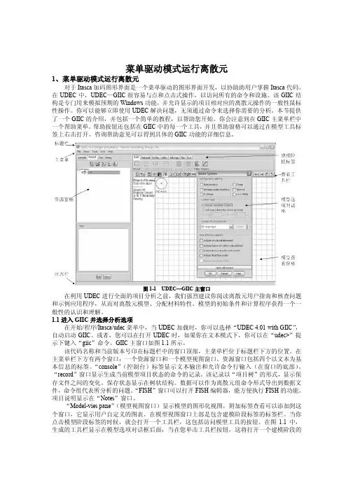
图1-1 UDEC—GIIC主窗口在利用UDEC进行全面的项目分析之前,我们强烈建议你阅读离散元用户指南和核查问题和示例应用程序,从而对离散元模型、分配材料特性、模型的初始条件和计算程序获得一个一般性的认识和理解。
1.1进入GIIC并选择分析选项在开始/程序/Itasca/udec菜单中,当UDEC加载时,你可以选择“UDEC 4.01 with GIIC”,自动启动GIIC。
或者,您可以在打开UDEC时,如果你在文本模式下,你可以在“udec>”提示下键入“giic”命令。
GIIC主窗口如图1.1所示。
该代码名称和当前版本号印在标题栏中的窗口顶部,主菜单栏位于标题栏下方的位置。
在主菜单栏下方有两个窗口:一个资源窗口和一个模型视图窗口。
资源窗口包括四个以文本为基本信息的标签。
“console”(控制台)标签显示文本输出和允许命令行输入(在窗口的底部)。
“record”窗口显示生成当前模型项目状态的命令的记录。
该记录以“项目树”的形式,显示保存文件之间的变化。
保存状态显示在树状结构。
数据可以作为离散元组命令形式导出到数据文件,命令组代表所分析的问题。
“FISH”窗口可以打开FISH编辑器,能方便执行FISH的功能。
dGB Earth Sciences. 专注于地球物理和地学软件解决方案OpendTect简介F3 –荷兰海上工区演示数据P.F.M. de Groot博士dGB Earth Sciences B.V.Nijverheidstraat 11-27511 JM EnschedeThe NetherlandsTel.; +31 53 4315155Fax,;+31 53 4315104e-mail; info@dgb-groupwebsite; dgb-group吴新天中国北京市海淀区花园东路32号花园公寓A1111目录1 关于OpendTectOpendTect是一个开源环境下的地震解释系统。
用户可以利用OpendTect的属性及现代可视化技术,如视频显示和体透视等三维可视化技术进行多个地震数据体的处理、浏览和解释。
还可通过一些免费和商业化的插件拓展OpendTect的功能。
1.1 OpendTect Base系统1.1.1 可视化地震解释员要求能够快速地浏览多个数据体,将所获得的信息综合起来以最优地理解研究对象的地质特征。
因此,OpendTect综合了先进的数据处理和可视化功能。
可视化对象可以灵活地在各数据空间中移动,以交互分析存储的数据或实时计算的数据。
体透视和视频浏览的功能是为了更好地理解数据和成果。
1.1.2 地震属性在OpendTect中,地震属性用于对地震数据进行筛选以及目标检测。
OpendTect在设计之初就旨在为解释人员提供最大的数据透视性,而且属性结果能够通过OpendTect的交互工作流程得到优化。
1.1.3 层位解释OpendTect提供多种层位追踪和解释选项。
同时还提供层位编辑以及层位计算等多种功能。
1.2 插件更多具体工作可借助商业插件dGB 以及第三方软件商为OpendTect 提供的插件来完成。
1.2.1 倾角控制倾角控制插件允许用户创建并使用控制数据体,这种控制数据体在每一个样点位置上都提取地震同相轴的倾角和方位角信息。
实例1——MODFLOW操作说明一、前言MODFLOW是一种用于地下水流动模拟的计算机模型,它是世界上最流行的地下水模拟软件之一,也是经常被用于环境工程和地下水资源管理的工具。
本文档旨在提供对MODFLOW的基本了解,以及针对实例1的操作说明。
二、MODFLOW简介1. MODFLOW的基本概念MODFLOW是一种水文地质模型,它可以通过使用数学模型来描述地下水流动过程。
这种模型可以帮助我们预测地下水位、渗透率和水流速度等参数,从而对地下水资源进行评估和管理。
2. MODFLOW的主要功能MODFLOW具有多种地下水流动过程中所需的模型,包括均匀流动、非均匀流动、非饱和-饱和流动、多孔介质输运、热传递等。
此外,MODFLOW也提供了一系列可视化和数据处理工具,方便用户从数据的角度对模型进行优化和调整。
3. MODFLOW的应用范围MODFLOW常被用于地下水资源管理、水文地质建模、地下水源热泵技术等领域。
此外,还可以用于模拟污染物在地下水系统中的传输和分布情况。
三、实例1——操作说明本实例基于MODFEOW中的单层稳态模型,目的是模拟一处地下水流流出的水源的情况。
以下为具体操作步骤。
1. 模型建立首先,需要在MODFLOW中创建相关的文件,包括模型输入文件、模型控制文件、模型数据文件等。
模型控制文件通常包括以下基本信息:•模型描述与标题•模型的计算规格(如时间步长、上限时间、和计算方法等)•输入输出文件的名称和路径•模型计算参数(如最小计算增量、最小收敛值、最大迭代次数等)等模型数据文件则描述了地形和水源的情况。
根据实际情况,可以选择导入COM 文件或手动输入数据。
2. 模拟计算完成模型建立后,可以开始进行模拟计算。
MODFLOW通常是使用迭代算法进行求解,计算结果会在控制文件中显示。
为了使计算结果更加准确,通常需要进行多次迭代。
在这个过程中可以根据需要对参数进行调整,如调整时间步长、收敛值等。
应用DNDC模型模拟关中地区农田长期施肥条件下土壤碳含量及作物产量陈海心;孙本华;冯浩;赵英;张延【期刊名称】《农业环境科学学报》【年(卷),期】2014(000)009【摘要】为探讨长期不同施肥条件下土壤有机碳和作物产量的变化规律及DNDC 模型在关中地区的适用性,利用在陕西杨凌设置的长期定位施肥试验数据,选取不施肥(CK)、单施氮磷钾无机肥(NPK)、无机肥配施秸秆(SNPK)、无机肥配施低量有机肥(M1NPK)及无机肥配施高量有机肥(M2NPK)5个处理,分析了20年来土壤有机碳(SOC)含量、碳循环以及农作物产量的变化趋势等基本特征。
分析数据表明:CK使得土壤肥力持续下降,显著地降低了SOC含量和作物产量;NPK处理虽可促进作物产量,但对表层土壤肥力的增加不明显,与CK处理无显著差异;而SNPK、M1NPK与M2NPK处理既增加了作物产量,同时也显著提高了土壤肥力,且以M2NPK的增产增肥效果最佳。
在此基础上,利用实测数据标定和验证了DNDC模型,通过均方根误差(RMSE),标准化的均方根误差(N-RMSE)以及符合度指数(d)对模型适用性分析,模型预测精度较好,可用于预测该地区作物产量和土壤有机碳动态。
从模型输出20年来土壤碳含量的变化看,施肥能提高作物地上部、地下部生物量以及土壤异氧呼吸作用,即同时提高了外源碳携入量和内源碳消耗量,但各施肥处理均在碳储量上表现为盈余状态。
因此,在关中地区,为提高土壤肥力、碳储量以及作物产量,可推广无机肥配施有机肥的措施。
【总页数】9页(P1782-1790)【作者】陈海心;孙本华;冯浩;赵英;张延【作者单位】西北农林科技大学水土保持研究所,陕西杨凌 712100;西北农林科技大学资源环境学院,陕西杨凌 712100;中国旱区节水农业研究院,陕西杨凌712100; 国家节水灌溉杨凌工程技术研究中心,陕西杨凌 712100;西北农林科技大学资源环境学院,陕西杨凌 712100;西北农林科技大学水利与建筑工程学院,陕西杨凌 712100【正文语种】中文【中图分类】S153.6【相关文献】1.应用DNDC模型分析施肥与翻耕方式对土壤有机碳含量的长期影响 [J], 王立刚;邱建军;马永良;王迎春2.农田冬季覆盖作物对土壤有机碳含量和主作物产量的影响 [J], 王丽宏;胡跃高;杨光立;曾昭海3.黑土长期施肥及养分循环再利用的作物产量及土壤肥力质量变化Ⅰ.作物产量 [J], 刘鸿翔;王德禄;王守宇;孟凯;韩晓增;张璐;沈善敏4.长期定位施肥条件下黄土旱塬农田作物产量、水分利用效率的变化 [J], 王淑英;樊庭录;丁宁平;赵刚5.基于DNDC模型模拟的冬小麦田土壤有机碳和作物产量对地表覆盖的响应 [J], 颜学斌;王俊;王科锋;白红英因版权原因,仅展示原文概要,查看原文内容请购买。

SOFT DOCINSTRUCTION MANUALFor Model 7290E Microtron® Variable Capacitance AccelerometerIM7290E, Revision AThe Model 7290E Microtron® is a rugged, variable capacitance accelerometer with integral electronics for voltage regulation, filtering and signal amplification. As is the practice with all instrumentation, certain precautions should be followed with check-out, mounting and recalibration.Materials RequiredAll the materials used in the mounting of the Model 7290E Microtron accelerometer are supplied with the unit inthe shipping container. These materials, as shown in Figure 1, include:(1)Allen wrench for 4-40 screws- Endevco P/N EHM464(2)4-40 x 7/16 inch Socket Head Cap Screws- Endevco P/N EH702(2)Size 4, Flat Washers- Endevco P/N EHW265For biaxial or triaxial acceleration measurements, the user should consider the Model 7990 Triaxial Mounting Block which is available as an optional accessory.Check-outBefore installation of the accelerometer, it should be checked to insure proper operation. A simple Zero Measurand Output and 2 g Turnover test can be conducted with minimal test equipment. Place the unit on itsside so that the accelerometer mounting surface is perpendicular to the table top. Apply the specified excitation voltage to the accelerometer (see data sheet for proper wiring hook-up) and measure the output with a dc millivolt meter. Allow the unit to warm-up for two minutes. The accelerometer should have a Zero Measurand Output (ZMO) within the specified limits in the data sheet.To perform the 2 g Turnover Test, the Model 7290E Microtron is oriented with its mounting surface on the tabletop (sensitive axis is vertical) and the output is measured with the dc millivolt meter. The unit is then turned over 180°, resulting in a change of 2 g, and the output is again noted. The sensitivity is computed by dividing the change in output by 2 g. The sensitivity in mV/g should be within the specified limits in the data sheet.If this initial check does not give a proper reading, indicating a possible malfunction, and the reason for the erroneous reading cannot b e found, contact Endevco at +1 (866) 363-3826.MountingWhen mounting the Model 7290E Microtron accelerometer, it is best to utilize the proper techniques and tools listed to ensure optimum performance. For triaxial acceleration measurements, the Model 7990 Triaxial Mounting Block is available - see paragraph 7 below.1.The mounting surface should be clean and free of burrs. Two #4-40 tapped holes, 0.2 inch minimum depth should be spaced 0.825 inches (20.96 mm) apart. A 32 micro inch rms surface finish with flatness of 0.0001 inches is recommended for the area that will contact the accelerometer. The sensitive axis of the unit is perpendicular to the mounting surface, so the angular alignment of the two mounting holes is not critical.2.If possible, do not cement the unit to the mounting structure. Use the supplied mounting washers and screws, as shown in Figure 1. Metric size screw M3 may also be used. Note: Adhesive mounting may be used, if necessary. Adhesion of epoxies to the hard anodized case is excellent, but thermal mismatch to the mounting surface can degrade the joint. A compliant adhesive, such as Dow Corning 3145 RTV, is recommended. Use care to maintain flatness of the unit during curing to reduce cross talk errors.FIGURE 1- Installation of Model 7290E Microtron Accelerometer3.Remove the unit from the shipping container. Place the unit on the mounting surface and align the mounting holes.4.Slide the washers over the screws. Using the supplied wrench or a torque wrench, tighten the screws to 6 lbf-in (0.7 Nm). This is roughly equivalent to finger tight with the supplied wrench.5.As practical, tie down the cable within 2 to 3 inches (4 to 6 cm) of the unit. Whipping of the cable during vibration and shock will strain the cable unnecessarily at the unit. The cable jacket is silicone, so care should be taken to avoid cutting or tearing the jacket. The cable is rated for 300°F (150°C) continuous service.6.Connect the unit to the signal conditioner using the following lead designation:Red- Excitation +Green- Output +White- Output -Black- Ground7.For triaxial acceleration measurements, the Model 7990 Mounting Block is attached to the mounting surface with three (3) 6-32 x 1 inch socket head cap screws as shown in Figure 2, with subsequent attachment of the (3)Model 7290E Microtron Accelerometers per steps 2 through 6 above.FIGURE 2- Installation of (3) Model 7290E Microtron Accelerometers onto Model 7990 Triaxial BlockElectrical Precautions1.Excitation- The Model 7290E Microtron has an internal voltage regulator, so excitation from +12.5 to +36 Vdc is adequate. A low noise power supply is recommended and care should be taken to minimize pickup on the cabling to the accelerometer. The maximum current drain over the entire operating range is 15 mA.2.Signal Leads- The g reen and white signal leads are differential. The green lead has a varying output, while the white lead is fixed at a reference voltage of approximately +2.5 Vdc. Although the output is high level, at ±2 Vdc, the usual precautions of using twisted pair, shielded instrumentation cable should be taken to avoid noise pickup on the signal leads.3.Grounding- The case of the Model 7290E Microtron is not attached to circuit ground, and the cable shield is not attached to the case or to circuit ground. The r ecommended grounding scheme is to ground the cable shield at the power supply ground and to no other point to avoid ground loops.4.Signal Conditioning- The Model 7290E Microtron has a high level differential output of ±2 Vdc, biased at 2.5 Volts. The 0 g reading, or Zero Measurand Output (ZMO), is 0 volts ± 50 mV. When the accelerometer is subjected to acceleration of 1 times range, the output of the unit will electrically clip, with a recovery time of < 10µseconds.5.Loading Effects- The Model 7290E Microtron accelerometer performs within specification limits while loaded with 10,000 ohm minimum resistance, and/or 0.1 µfarad maximum capacitance.Shunt CheckA Shunt Check is performed in applications where the Model 7290E Microtron accelerometer is already mounted on a test structure and cannot be dynamically checked with a 2 g Turnover test. Full details of the Shunt Check procedure is contained in Endevco Tech Data A542.However, in brief, the shunt check is performed by connecting a precision fixed resistor of known value to the positive output (green lead) of the accelerometer. The other end of the shunt resistor is connected to an excitation voltage source to promote output shifts simulating positive direction accelerations, or to circuit ground for shifts in the negative direction.The nominal output voltage shift (E sh) based on the fraction of full scale reading desired is:E sh= SENS * FS * nwhere: E sh = output voltage shift, VdcSENS = sensitivity, volts/gFS = ± full scale acceleration, gn = fraction of full scale readingKnowing the desired output voltage shift, (E sh) the value of the external shunt resistor (R sh) is:R sh = (V sh - V ent - V wh - E sh) x R out____________________________________E shOr conversely, given the value of the external shunt resistor (R sh), the expected output voltage shift, (E sh ) is:E sh = (V sh - V out - V wh) * R out_______________________R sh + R outwhere: R sh = selected external shunt resistorV sh= voltage applied to shunt resistor (for + acceleration shifts, connect to excitation, V sh =+9.5 to 18.0 Vdc and for negative acceleration shifts, connect to circuit ground, V sh = 0 Vdc)V out = output signal measurement unshunted, Vdc (positive output signal (green) withrespect to negative output signal (white))V wh = negative output signal (white) with respect to ground, V wh= 3.5 ±0.1 VdcR out = output impedance, ohms (R out = 470 ± 24 ohms, ±100 ppm/°C)E sh = output voltage shift, VdcThermal errors have no significant effect on accuracy as long as the unshunted and shunted measurements are taken at the same temperature.RecalibrationSensitivity and Zero Measurand Output calibration should be performed at 6 to 12 month intervals, depending on usage. Ordinarily, recalibration need be performed only at 12 month intervals if it is known that the accelerometer has not been used beyond its rated specifications. If the unit is used under severe environments, it may be desirable to use shorter calibration intervals.Contact Endevco for local calibration facility information or return the unit to Endevco for recalibration. Endevco maintains an accelerometer recalibration service with NIST traceability in the United States. Endevco European Regional offices maintain accelerometer recalibration services with traceability to national standards.Dirty units may be wiped clean using a damp cloth and a solvent such as acetone.QuestionsIf you have any questions regarding the use of this or any Endevco accelerometer, please contact Endevco at +1 (866) 363-3826 in North America, or your local sales representative.。

基于DNDC模型的不同耕作措施下农田土壤碳循环模拟研究基于DNDC模型的不同耕作措施下农田土壤碳循环模拟研究摘要:土壤有机碳是维持农田生态系统稳定的重要组成部分,对于探索可持续农业发展具有重要意义。
本研究基于DNDC (Denitrification-Decomposition)模型,对旱地和水田两种耕作模式下的不同耕作措施对农田土壤碳循环的影响进行了模拟研究,结果显示不同耕作措施对土壤碳循环有明显的影响。
1. 引言土壤有机碳是土壤中最重要的碳库之一,其含量的变化对于土壤质量、作物生长和环境质量具有重要影响。
农田土壤有机碳的积累和稳定化是可持续农业发展的关键。
因此,研究不同耕作措施对农田土壤碳循环的影响,对于推动农田生态系统的可持续发展至关重要。
2. 研究方法本研究选择旱地和水田两种耕作模式,通过DNDC模型模拟不同耕作措施下农田土壤碳循环的情况。
具体耕作措施包括传统耕作、潜水保墒、轮作、有机肥施用等。
通过模拟计算土壤碳储量、碳释放和碳吸收等指标,分析不同耕作措施对土壤碳循环的影响。
3. 结果与讨论结果显示,在旱地耕作模式下,不同耕作措施对土壤碳循环的影响较为明显。
传统耕作方式下,土壤有机碳的储量和积累速度较低,土壤碳释放迅速。
而采用潜水保墒方式,可以有效提高土壤有机碳的储量和积累速度,降低土壤碳释放速率。
轮作和有机肥施用可以进一步提高土壤有机碳的储量和稳定性,促进土壤对碳的吸收和固定。
在水田耕作模式下,不同耕作措施对土壤碳循环的影响相对较小。
由于水田地下水位较高,土壤有机质分解速度较慢,因此土壤有机碳的储量相对较高。
在水田中,潜水保墒方式的土壤碳储量更高,而传统耕作方式下土壤碳释放比较快。
4. 结论本研究通过基于DNDC模型的模拟研究,发现不同耕作措施对农田土壤碳循环具有显著影响。
在旱地耕作模式下,采用潜水保墒、轮作和有机肥施用等措施可以有效提高土壤有机碳的储量和稳定性。
而在水田耕作模式下,潜水保墒方式尤其重要,能够有效保持土壤有机碳的储量。
DNDC模型使用手册( 9.3版本)新罕布什尔大学地球海洋与空间研究所2010年1月15日致谢我们感谢美国国家科学基金会(NSF)、美国航天与空间总署(NASA)、美国农业部(USDA)、环境保护署(EPA)、国家海洋与大气总署(NOAA)及国家大气研究中心(NCAR/UCAR)自1989年以来为发展DNDC模型所提供的持续支持。
世界许多国家的科研人员为该模型的发展做出了贡献,他们或为模型验证提供数据,还为模型添加新的功能。
这些研究者包括李长生(Changsheng Li美国)、斯苐夫·富罗京(Steve Frolking美国)、罗伯特·哈里斯(Robert Harriss美国)、里查德·泰瑞(Richard Terry美国)、麦克·凯雷(Michael Keller美国)、帕提克·葛瑞尔(Patrick Crill美国)、安姬·卫紫(Antje Weitz德国)、泰德·派克(Ted Peck美国)、卫理·温岚德(Wayne Wendland美国)、大卫·金克森(David Jenkinson英国)、王英平(Yingping Wang澳大利亚)、庄亚辉(Yahui Zhuang 中国)、戴昭华(Zhaohua Dai中国)、罗尔·布兰特(Roel Plant 荷兰)、周叶(Ye Zhou中国)、张宇(Yu Zhang中国)、林清华(Qinghua Lin中国)、王晓科(Xiaoke Wang中国)、富罗里安·史坦格(Florian Stange德国)、克劳斯·布特巴赫-巴尔(Klaus Butterbach-Bahl德国)、汉斯·帕潘(Hans Papen德国)、索菲亚·泽克美斯特-波坦斯顿(Sophie Zechmeister-Boltenstern奥地利)、郑循华(Xunhua Zheng中国)、孙建中(Jianzhong Sun中国)、秦晓光(Xiaoguang Qin中国)、斯蒂夫·佳伟斯(Steve Jarvis英国)、布朗尼·斯依德(Bronwyn Syed英国)、劳娜·布朗(Lorna Brown英国)、雷·德斯佳丁(Ray Desjardins加拿大)、沃特·斯密思(Ward Smith加拿大)、布莱安·格兰特(Brian Grant 加拿大)、罗·萨斯(Ron Sass美国)、黄燿(Yao Huang中国)、蔡祖聪(Zucong Cai中国)、康国鼎(Guoding Kang中国)、佳瑞亚·波佳瓦特(Jariya Boonjawat泰国)、鹤田治雄(Haruo Tsuruta 日本)、泽本卓治(Ta kuji Sawamoto 日本)、小林和彦(Kazuhiko Kobayashi日本)、邱建军(Jianjun Qiu中国)、拉福·柯斯(Ralf Kiese德国)、卡尔·特伦蒂(Carl Trettin美国)葛荪(Sun Ge美国)、徐成一(Cheng-I Hsieh台湾)、雷纳德·莱姆克(Reynald. Lemke加拿大)、瑟雷德·萨喀(Surinder Saggar新西兰)、罗波·安德欧(Robbie Androw新西兰)、阿温·缪斯(Arvin Mosier美国)、卡罗斯·爱得阿多(Carlos Eduardo巴西)、程根伟(Genwei Cheng中国)、卡里·明科恩(Cari Minkkinen芬兰)、雷诺·华兹曼(Reiner Wassmann德国)、雷·斯玛喀甘( Nui Smakgahn 泰国)、旭日(Xu Ri中国)、罗达·兰亭(Rhoda Lantin菲律宾)、罗伯特·雷(Robert Rees英国)、中川阳子(Yoko Nakagawa 日本)、丽达·法拉芭莎赞德(Neda Farahbakhshazad美国)、威廉·萨拉斯(William Salas美国)、斯蒂夫·波斯(Steve Boles美国)、麓多门(Tamon Fumoto 日本)、玛格达·克斯喀(Magda Kesik德国)、唐娜·基尔特拉普(Donna Giltrap新西兰)、纳拉辛哈·萨帕里(Narasinha Shurpali芬兰)、赫曼舒·帕德克(Himanshu Pathak印度)、加格蒂斯·巴布依日帕蒂(Jagadeesh Babu Yeluripati印度)、达安·巴赫德特(Daan Baheydt比利时)、斯蒂文·斯罗特尔(Steven Sleutel比利时)、八木一行(Kazuyuki Yagi 日本)、丹·杰伊斯(Dan Jaynes美国)、坦娜·泰娜斯(Dana Dinners美国)、丹尼斯·麦克劳林(Dennis Mclaughlin美国)、克里斯蒂娜·托里特(Christina Tonitto 美国)、卡尔斯蒂·托普(Kairsty Topp英国)、劳拉·克蒂娜斯(Laura Cardenas英国)、泰德·迈克尔(Todd Mitchell美国)、张凡(Fan Zhang中国)、周再兴(Zaixing Zhou中国)、邓佳(Jia Deng 中国)、朱波(Bo Zhu中国)、王立刚(Ligang Wang中国)、富兰克·密莱尔(Frank Mitloehner美国)、乔基·木拉毛特 (Joji Muramoto美国)、朱丽叶·库芭托瓦(Juliya kurbatova俄国)、安德烈·瓦尔金(Andrej Varlegin俄国)、娜塔丽娅·芭克娜(Natalya Buchkina俄国)、陈德立(Deli Chen澳大利亚)、李勇(Yong Li澳大利亚)、鲁伊斯·巴登(Louise Barton澳大利亚)、坦妮拉·克拉奇(Daniela Kracher德国)、托德·富罗京(Tod Frolking美国)、友瑞娜·可瓦克(Yurina Kwack日本)。
1.液力变矩器CFD仿真操作教程本章对液力变矩器数值仿真流程和步骤进行详细说明。
PumpLinx算例文件目录下会生成几个重要文件,其中“.sgrd”文件为网格文件,记录网格信息;“.spro”文件为工程文件,记录模型及边界条件设置信息;如需打开一个完整的算例,工程文件和网格文件缺一不可。
“.stl” 文件为PumpLinx支持的几何模型导入格式。
1.1 液力变矩器几何模型导入►液力变矩器由泵叶轮、导叶、涡轮这三个部分组成,在CAD软件中将叶轮、导叶、涡轮分别以stl格式导出。
►注意:在导出几何模型之前,需要将叶轮、导叶、涡轮分成三个部分,以便在进行数值仿真时可以顺利生成动/静流体域之间的交互面。
如下图所示:►运行PumpLinx软件,新建一个工程文件,界面如下:1.2 切分液力变矩器边界面1.2.1 对液力变矩器泵叶轮流体域进行分区►选择界面左边的Mesh窗口命令(一共4个窗口选项,分别是Mesh、Model、Simulation 和Result,分别代表各个步骤)。
►选择“ Import/Export Geometry or Grid”命令,点击“ Import Surface From STL TriangulationFile” ,选择事先从CAD文件中导出的泵叶轮的stl文件,如图所示:►点击“ Split/Combine Geometry or Grid”命令,点击“Split by Angle”选项,几何体被分为Impeller_wall_01至Impeller_wall_20数个部分,由于设置了“Maximum Num. of Splits”值为20,因此最多允许划分的几何面为20。
►重命名“Impeller_wall_02”为“Impeller_mgi_reactor”重命名“Impeller_wall_03”为“Impeller_mgi_turbine►点击“ Split/Combine Geometry or Grid”命令,选择“combine”命令合并“Impeller_wall_01”,“Impeller_wall_04”至“Impeller_wall_20”,并命名为“Impeller_wall”。
DNDc模型在生态系统中的应用1. 应用背景生态系统是一个复杂而庞大的系统,由各种生物和非生物要素相互作用而形成。
人们对于生态系统的研究和管理越来越重视,因为生态系统不仅维持着生物多样性和生态平衡,还提供了许多生态服务,如水源保护、土壤保持、气候调节等。
因此,开展生态系统的数字化模拟研究对于科学理解和有效管理生态系统具有重要意义。
DNDc模型是一个用于模拟土壤碳氮矿化和去除过程的生态系统模型,广泛应用于农业、林业和草地生态系统的研究和管理。
它可以预测土壤中有机碳和氮的变化,并评估不同管理措施对土壤碳氮循环的影响。
DNDc模型以动态的方式模拟土壤中碳氮矿化和去除过程,不仅可以帮助我们了解生态系统的功能和变化,还可以辅助决策制定和资源管理。
2. 应用过程2.1 模型输入DNDc模型的应用需要一些必要的输入数据,包括生物量、土壤性质、气候等。
其中,生物量数据用于估算碳氮输入和去除的速率,土壤性质数据用于估算土壤碳氮储量和氮矿化速率,气候数据用于估算土壤温度和湿度对碳氮矿化的影响。
2.2 模型参数化为了模拟特定的生态系统,DNDc模型需要根据实际情况进行参数化。
参数化是根据实地观测或实验数据,根据生态系统的特点和条件,确定模型中的参数值,使模型能够准确地反映生态系统的物质转化过程。
这些参数包括有机质分解速率、氮释放速率、氮固定速率等。
2.3 模型运行在模型参数化完成后,可以通过模型运行来模拟生态系统中的碳氮矿化和去除过程。
模型根据输入数据和参数值,计算并预测生态系统中碳氮的矿化和去除速率,以及土壤中碳氮的储量变化。
模型通常以时间步长为单位进行计算,可以预测未来几个月或几年的碳氮循环情况。
2.4 模型验证在模型运行完成后,需要对模型的结果进行验证。
模型验证是通过与实际观测数据进行比较,评估模型的准确性和可靠性。
比较模型输出和实测数据可以验证模型在模拟土壤碳氮循环过程中的准确性,并找出模型的不足之处。
3. 应用效果3.1 科学研究DNDc模型在科学研究中广泛应用,为生态系统的功能和变化提供了重要的模拟工具。
dndc模型模拟碳固存碳固存是指将二氧化碳气体从大气中捕获并储存起来,以减少其对地球气候系统的影响。
Dndc模型是一种用于模拟土壤碳、氮、水和气体循环的模型。
本文将运用Dndc模型来模拟碳固存的过程,并探讨其在应对气候变化中的潜力。
我们需要了解Dndc模型是如何工作的。
该模型基于土壤的物理、化学和生物过程,以及气候条件等因素,通过模拟土壤中有机碳的分解、氮的转化和植物的生长等过程,来预测土壤碳和氮的动态变化。
通过对这些过程的模拟,可以评估不同土地利用方式对碳固存潜力的影响,并为制定有效的碳固存策略提供科学依据。
在模拟过程中,我们需要输入一系列参数,如土壤类型、植被类型、施肥水平等。
这些参数将影响土壤中有机碳的积累和分解速率。
通过模拟不同的土地利用方式和管理措施,我们可以比较它们对土壤碳固存的效果,并选择最佳的策略来提高碳固存能力。
通过Dndc模型的模拟结果,我们可以得出一些有关碳固存的重要结论。
首先,不同土地利用方式对碳固存的影响是不同的。
例如,在农田中,合理的农业管理措施可以增加土壤中的有机碳含量,而森林等自然生态系统可以充分发挥其固碳的潜力。
其次,施肥和植被覆盖等因素也会对碳固存起到重要作用。
适当的施肥可以提供植物生长所需的养分,促进土壤中的碳固存;而植被覆盖可以减少土壤侵蚀,保护土壤有机碳不被氧化分解。
Dndc模型还可以用来评估不同管理措施对碳固存潜力的影响。
例如,通过模拟不同的农业管理措施,如有机农业和保护性耕作,可以评估它们对碳固存的贡献。
通过比较不同策略的模拟结果,可以选择最佳的管理措施来增加土壤中的有机碳含量。
然而,需要注意的是,Dndc模型只是一个工具,模拟结果可能存在一定的不确定性。
模型的准确性受到输入参数的精度和模型假设的影响。
因此,在使用Dndc模型进行碳固存模拟时,需要确保输入参数的准确性,并结合实际情况进行科学合理的模拟。
Dndc模型是一种用于模拟碳固存的重要工具。
通过模拟不同土地利用方式和管理措施,可以评估它们对碳固存的影响,并选择最佳的策略来增加土壤中的有机碳含量。