德马格技术说明
- 格式:doc
- 大小:16.00 KB
- 文档页数:4
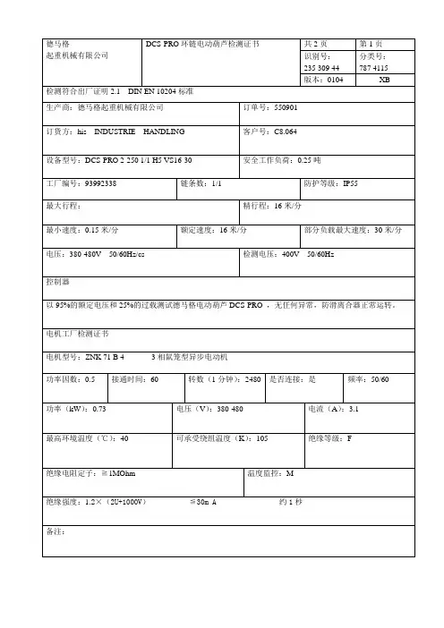
德马格起重机械有限公司DCS-PRO环链电动葫芦检测证书共2页识别号:235 309 44版本:0104第1页分类号:787 4115XB检测符合出厂证明2."1DIN EN 10204标准生产商:德马格起重机械有限公司订货方:hisINDUSTRIEHANDLING订单号:550901客户号:C8."064设备型号:DCS-PRO 2-250 1/1 H5 VS16-30工厂编号:最大行程:最小速度:0."15米/分电压:380-480V50/60Hz/cs链条数:1/1安全工作负荷:0."25吨防护等级:IP55精行程:16米/分额定速度:16米/分部分负载最大速度:30米/分检测电压:400V50/60Hz控制器以95%的额定电压和25%的过载测试德马格电动葫芦DCS-PRO,无任何异常,防滑离合器正常运转。
电机工厂检测证书电机型号:ZNK 71 B 43相鼠笼型异步电动机功率因数:0."5接通时间:60转数(1分钟):2480是否连接:是频率:50/60功率(kW):0."73电压(V):380-480电流(A):3."1最高环境温度(℃):40可承受绕组温度(K):105绝缘等级:F绝缘电阻定子:≧1MOhm温度监控:M绝缘强度:1."2×(2U+1000V)≦30m A约1秒备注:德马格起重机械有限公司DCS-PRO环链电动葫芦检测证书共2页识别号:235 309 44版本0104第2页分类号:787 4115XB起重吊钩检测证书吊钩类型:简易吊钩起重吊钩标识供应商商标:PS起重吊钩检测最大测试力(k N):(变形<0."25%)材料特性:34CrMo4 EN10083化学成分在-20℃的性能RelA(≥)J(≥)MPa(≥)强度等级:V起重吊钩号码:2标准:DIN15400融化编号:吊钩最大承受力:C(≤)Si(≤)MnP(≤)S(≤)Cr(≤)Mo(≤)R meMPa0."370."400."60-0."900."0350."0350."90-1."200."15-0."30实际功率在额定功率范围内精确性:所有数据都在允许误差范围之内起重吊钩无影响使用的表面裂纹和裂痕。

DGT40轻型矿用汽车介绍德马格(DURMAX)DGT系列轻型矿车,是武汉德联重工XXX(DURLAN)借鉴国外经典矿用汽车结构/技术优势和先进设计理念,针对国内市场条件和使用特点,精心打造的新一代轻型矿用汽车系列产品。
轻型矿车,也称为通用型矿车(General mining truck),是相对于4X2经典矿车而言,一般是采用6X4结构,包含有经典矿车的重要技术特征(如悬架系统等),体现了对矿山道路的良好适应能力。
其整车重量利用系数高,车体重量轻,整车寿命适中,价格、使用维护成本低。
在产品的技术性能、使用功能、应用范围、用户群体、采购使用维护成本等各方面,具有更加广泛的通用性和适用性。
而之前的宽体矿车,是相对于公路重卡而言,车身进行了加宽。
其自身的技术架构依然是沿用公路重卡结构,缺少经典矿车的关键技术特征。
德马格(DURMAX)DGT系列轻型矿车,是德联重工矿车系列产品中的一个重要分支。
DGT是:DURLAN General mining Truck的缩写。
DGT40是德马格(DURMAX)轻型矿车系列的第一个产品,采用6X4驱动方式,载重40短吨级。
在保持之前宽体矿车:整车及零部件通用性强、保有量大、供应渠道广、使用成本低等诸多优势外,还融入了国外经典4X2矿用汽车、6X6铰接式矿车一些具有代表性的关键技术及结构设计元素,因而对矿山道路具有非常良好的适应性。
这些特质使得DGT40轻型矿车:在整车性能、使用寿命和出勤率等方面得到显著提升。
同时,降低了使用故障率以及后期的使用维护成本,从而使得DGT40轻型矿车获得了最佳性价比。
一、技术背景目前的宽体矿车仍采用公路重卡底盘结构。
其采用的钢板弹簧悬架具有典型的公路车辆特征,对矿山路面的适应能力很差。
随着载荷的增加,宽体矿车额定装载量已经超过钢板弹簧技术架构的承载极限。
随着板簧数量的增加,板簧整体的可变形量以及对地面的补偿能力大幅下降。
另外,整车质量也超出了原有标准液压减震器的设计容量,一般仅能在前桥布置一组,中后桥完全靠钢板弹簧减震。
尊敬的顾客:
感谢您选用德马格电动葫芦。
为了方便您的选择和链条组的进一步简化,从2006年4月起我们将会对现有的几个方面实行新的构建方案。
1.规格标识:取消DC20标准。
未来将会把DC10和DC20统一称为DC10。
两者的区别在于下料的长度。
2.速度方面:消除V1,V2和VS之间的差异。
V后面的数字直接代表最大和平均提升速度,DCS型号代表额定和最大速度。
3.FEM分级:与载荷跃变递减相适应。
很抱歉我们现在不能为您提供最新的链条组资料。
请参阅本页后面的新旧模型代码。
感谢您的合作。
安全检验证书
德马格环链电动葫芦DC-Pro,DCS-Pro,DC-Com
德马格手控葫芦DSM-Pro,DCMS-Pro
操作人员必须仔细阅读使用说明
产品型号:DCS-PRO
生产年份:2008
驱动机构总成2m+/M5+
起重量:0.25吨
工厂代码:93992338
运行速度
德马格起重机械有限公司
邮政专用信箱67 D-58286
电话(02335)92-0
传真(02335)927676
CE认证附在使用说明中。
本款产品属于德马格最新型产品。
本产品的安装,生产和技术规定已经得到权威人士的签字认证。
(通过德国《伤害保险》“电动设备和生产手段”第4章,第5条认证)。
德马格PK型环链电动葫芦的应用及特点6科技资讯科技资讯S I N &T NOLOGY I NFORM TI ON 2008N O .10SCI ENC E &TECH NOLOG Y I N FOR M A TI ON 学术论坛德马格(DEM AG)PK 型环链电动葫芦是德国曼内斯曼德马泰克物料输送技术股份公司设计制造的成功产品之一,自投入市场以来,仅在欧洲就已销售了150多万台。
1997年,曼内斯曼德马泰克公司在我国秦皇岛设立了合资子公司,子公司以部件进口,国内组装的所谓CKD 方式生产母公司的德马格PK 型环链电动葫芦,从而使德马格PK 型葫芦进入中国市场。
本文结合实际对德马格PK 型环链电动葫芦的应用场合及方式、特点、环链葫芦与钢丝绳葫芦的比较等方面进行分析。
1德马格PK 型环链电动葫芦的应用PK 型环链电动葫芦的应用场合非常广,遍及机械制造、冶金矿山、交通运输、轻工化工、林业和建筑等各行各业,可以说,凡需实现4t 以下物料搬运的场合都可以使用PK 型葫芦。
在具体应用中,PK 型环链电动葫芦分有固定式和移动式两种。
1.1固定式独立适用在需要定点起吊物料的场合,即将葫芦悬挂在一固定位置,接通电源,可上下垂直起降物料。
1.2移动式应用在要求覆盖线或面的工作场合。
移动式葫芦分有以下四种连接方式:与工字钢轨道或H 型钢轨道连接的运行小车方式,运行小车的规格型号及与PK 型葫芦的适配可参见P K 型环链电动葫芦产品样本。
运行小车有手动运行和电动运行之分,其中手动运行小车可通过曳引手电门或吊钩来运行,操作灵活方便。
电动运行小车由锥形转子电动机、减速器、墙板、车轮和横梁等件组成。
电动运行小车适用于长距离或自动输送线上的运行。
小车车轮有圆锥和圆柱两种不同踏面形成,分别适用于工字钢轨道和H 型钢轨道。
与德马格KBK 轨道的连接,这种轨道采用优质钢轧制,经组焊成形。
其供电可通过简单灵活的联接组合,不但能形成独立的搬运线路,还能通过各种标准部件的组合,使独立的单台设备能有机地组成一个系统,实现复杂路线的物料搬运以及各工位间物料传递及物料储运分配等强大的网络功能。
1760500275585/6851085/1185770x770520x5201605929International size description 国际标准尺寸Locking force 锁模力 [kN]Max. mould opening stroke 最大开模行程 [mm]Min. mould height 最小模厚 [mm]Max./enlarged mould height 最大/增大模厚 [mm]Overall size of platens/enlarged 最大/增大模板间距 [mm]Mould platen(h x v) 模板尺寸(水平*垂直) [mm]Distance between tie bars(h x v) 拉杆间距(水平*垂直) [mm]Ejection stroke 顶出行程 [mm]Ejection force 顶出力 [kN]Retraction force 回缩力 [kN]Screw geometry 螺杆形状L/D ratio 长径比Spec. injection pressure(up to 400℃) 注射压力(至400℃) [bar]Max. cylinder head volume 理论注射容积 [cm3]Max. shot weight(PS) 最大注射量 [g]Max.Rate of injection1)最大注射速率1)> without accumulator 2) > 无蓄能器2) [cm3/s]> with accumulator > 加蓄能器 [cm3/s]Injection Speed 注射速度Under 1000bar injection pressure 在1000bar 的注射压力下> without accumulator [mm/s]> with accumulator [mm/s]Plasticising rate(PS) 塑化率(PS)> motor 1(120bar)2) > 马达1(120bar)2) [g/s]> motor 2(120bar)2) > 马达2(120bar)2) [g/s]> electric screw drive > 电动螺杆 [g/s]Max. screw stroke 最大螺杆行程 [mm]Max. distance of nozzle retraction3) 最大喷嘴行程3) [mm]Nozzle stroke in automatic mode3) 喷嘴工作行程3) [mm]Max. nozzle dipping depth(SVO) 最大喷嘴伸出模板长度(SVO) [mm]Nozzle sealing force 喷嘴接触力 [kN]Number of heating zones 加热段数量Hopper capacity4) 料斗容积4) [Itr.]Oil tank capacity 油箱容量 [Itr.]Installed electrical rating 额定电气功率> pump2) > 油泵2) [≈kW]> electric screw drive > 电动螺杆 [≈kW]> heating capacity of screw cylinder > 料筒加热功率 [≈kW]> capacity with hydraulic drive2) > 液压驱动功率 2) [kW]> capacity with electr. drive2) > 电气总功率2) [kW]Dry cycles(Euromap6)2) 空循环(EUROMAP6)2) [s-mm]Net weight(without oil)5) 机器净重(不含油)5) [≈kg]Machine dimensions(lxwxh) 机器尺寸(lxwxh) [≈m]Motor end projection 1(H)6) 液压马达末端伸出机身距离 1(H)6) [mm]Motor end projection 2(H)6) 液压马达末端伸出机身距离 2(H)6) [mm]Electric drive projection (H)6) 预塑电动马达伸出机身距离 (H)6) [mm]The shown specifications reflect the state at the time of printing. We 1) Rate of injection based on the standard plasticizing unit1)注射速率基于标准塑化装置2310575340690/7901265/1365860x860580x5801807336International size description 国际标准尺寸Locking force锁模力 [kN]Max. mould opening stroke 最大开模行程 [mm]Min. mould height 最小模厚 [mm]Max./enlarged mould height 最大/增大模厚 [mm]Overall size of platens/enlarged 最大/增大模板间距 [mm]Mould platen(h x v)模板尺寸(水平*垂直) [mm]Distance between tie bars(h x v) 拉杆间距(水平*垂直) [mm]Ejection stroke 顶出行程 [mm]Ejection force 顶出力 [kN]Retraction force 回缩力 [kN]Screw geometry 螺杆形状L/D ratio长径比Spec. injection pressure (up to 400℃) 注射压力(至400℃) [bar]Max. cylinder head volume 理论注射容积 [cm 3]Max. shot weight(PS) 最大注射量 [g]Max.Rate of injection 1)最大注射速率1)> without accumulator 2) > 无蓄能器2) [cm 3/s]> with accumulator > 加蓄能器[cm 3/s]Injection Speed注射速度Under 1000bar injection pressure在1000bar 的注射压力下> without accumulator [mm/s]> with accumulator[mm/s]Plasticising rate(PS) 塑化率(PS)> motor 1(120bar)2)> 马达1(120bar)2)[g/s]> motor 2(120bar)2) > 马达2(120bar)2) [g/s]> electric screw drive > 电动螺杆 [g/s]Max. screw stroke最大螺杆行程 [mm]Max. distance of nozzle retraction 3) 最大喷嘴行程3) [mm]Nozzle stroke in automatic mode 3)喷嘴工作行程3)[mm]Max. nozzle dipping depth(SVO) 最大喷嘴伸出模板长度(SVO) [mm]Nozzle sealing force 喷嘴接触力 [kN]Number of heating zones 加热段数量Hopper capacity 4)料斗容积4)[Itr.]Oil tank capacity油箱容量 [Itr.]Installed electrical rating 额定电气功率> pump 2)> 油泵2) [≈kW]> electric screw drive> 电动螺杆 [≈kW]> heating capacity of screw cylinder > 料筒加热功率 [≈kW]> capacity with hydraulic drive 2)> 液压驱动功率 2)[kW]> capacity with electr. drive 2) > 电气总功率2) [kW]Dry cycles(Euromap6)2)空循环(EUROMAP6)2)[s-mm]Net weight(without oil)5) 机器净重(不含油)5)[≈kg]Machine dimensions(lxwxh) 机器尺寸(lxwxh) [≈m]Motor end projection 1(H)6) 液压马达末端伸出机身距离 1(H)6)[mm]Motor end projection 2(H)6) 液压马达末端伸出机身距离 2(H)6) [mm]3080675330710/8301385/1505930x930630x6302007336International size description 国际标准尺寸Locking force 锁模力 [kN]Max. mould opening stroke 最大开模行程 [mm]Min. mould height 最小模厚 [mm]Max./enlarged mould height 最大/增大模厚 [mm]Overall size of platens/enlarged 最大/增大模板间距 [mm]Mould platen(h x v) 模板尺寸(水平*垂直) [mm]Distance between tie bars(h x v) 拉杆间距(水平*垂直) [mm]Ejection stroke 顶出行程 [mm]Ejection force 顶出力 [kN]Retraction force 回缩力 [kN]Screw geometry 螺杆形状L/D ratio 长径比Spec. injection pressure(up to 400℃) 注射压力(至400℃) [bar]Max. cylinder head volume 理论注射容积 [cm3]Max. shot weight(PS) 最大注射量 [g]Max.Rate of injection1)最大注射速率1)> without accumulator 2) > 无蓄能器2) [cm3/s]> with accumulator > 加蓄能器 [cm3/s]Injection Speed 注射速度Under 1000bar injection pressure 在1000bar 的注射压力下> without accumulator [mm/s]> with accumulator [mm/s]Plasticising rate(PS) 塑化率(PS)> motor 1(120bar)2) > 马达1(120bar)2) [g/s]> motor 2(120bar)2) > 马达2(120bar)2) [g/s]> electric screw drive > 电动螺杆 [g/s]Max. screw stroke 最大螺杆行程 [mm]Max. distance of nozzle retraction3) 最大喷嘴行程3) [mm]Nozzle stroke in automatic mode3) 喷嘴工作行程3) [mm]Max. nozzle dipping depth(SVO) 最大喷嘴伸出模板长度(SVO) [mm]Nozzle sealing force 喷嘴接触力 [kN]Number of heating zones 加热段数量Hopper capacity4) 料斗容积4) [Itr.]Oil tank capacity 油箱容量 [Itr.]Installed electrical rating 额定电气功率> pump2) > 油泵2) [≈kW]> electric screw drive > 电动螺杆 [≈kW]> heating capacity of screw cylinder > 料筒加热功率 [≈kW]> capacity with hydraulic drive2) > 液压驱动功率 2) [kW]> capacity with electr. drive2) > 电气总功率2) [kW]Dry cycles(Euromap6)2) 空循环(EUROMAP6)2) [s-mm]Net weight(without oil)5) 机器净重(不含油)5) [≈kg]Machine dimensions(lxwxh) 机器尺寸(lxwxh) [≈m]Motor end projection 1(H)6) 液压马达末端伸出机身距离 1(H)6) [mm]Motor end projection 2(H)6) 液压马达末端伸出机身距离 2(H)6) [mm]3850730350745/9501475/16801040x1060720x7202007336International size description 国际标准尺寸Locking force 锁模力 [kN]Max. mould opening stroke 最大开模行程 [mm]Min. mould height 最小模厚 [mm]Max./enlarged mould height 最大/增大模厚 [mm]Overall size of platens/enlarged 最大/增大模板间距 [mm]Mould platen(h x v) 模板尺寸(水平*垂直) [mm]Distance between tie bars(h x v) 拉杆间距(水平*垂直) [mm]Ejection stroke 顶出行程 [mm]Ejection force 顶出力 [kN]Retraction force 回缩力 [kN]Screw geometry 螺杆形状L/D ratio 长径比Spec. injection pressure(up to 400℃) 注射压力(至400℃) [bar]Max. cylinder head volume 理论注射容积 [cm3]Max. shot weight(PS) 最大注射量 [g]Max.Rate of injection1)最大注射速率1)> without accumulator 2) > 无蓄能器2) [cm3/s]> with accumulator > 加蓄能器 [cm3/s]Injection Speed 注射速度Under 1000bar injection pressure 在1000bar 的注射压力下> without accumulator [mm/s]> with accumulator [mm/s]Plasticising rate(PS) 塑化率(PS)> motor 1(120bar)2) > 马达1(120bar)2) [g/s]> motor 2(120bar)2) > 马达2(120bar)2) [g/s]> electric screw drive > 电动螺杆 [g/s]Max. screw stroke 最大螺杆行程 [mm]Max. distance of nozzle retraction3) 最大喷嘴行程3) [mm]Nozzle stroke in automatic mode3) 喷嘴工作行程3) [mm]Max. nozzle dipping depth(SVO) 最大喷嘴伸出模板长度(SVO) [mm]Nozzle sealing force 喷嘴接触力 [kN]Number of heating zones 加热段数量Hopper capacity4) 料斗容积4) [Itr.]Oil tank capacity 油箱容量 [Itr.]Installed electrical rating 额定电气功率> pump2) > 油泵2) [≈kW]> electric screw drive > 电动螺杆 [≈kW]> heating capacity of screw cylinder > 料筒加热功率 [≈kW]> capacity with hydraulic drive2) > 液压驱动功率 2) [kW]> capacity with electr. drive2) > 电气总功率2) [kW]Dry cycles(Euromap6)2) 空循环(EUROMAP6)2) [s-mm]Net weight(without oil)5) 机器净重(不含油)5) [≈kg]Machine dimensions(lxwxh) 机器尺寸(lxwxh) [≈m]Motor end projection 1(H)6) 液压马达末端伸出机身距离 1(H)6) [mm]Motor end projection 2(H)6) 液压马达末端伸出机身距离 2(H)6) [mm]4620770380825/10501595/18201200x1200820x8202309642International size description 国际标准尺寸Locking force 锁模力 [kN]Max. mould opening stroke 最大开模行程 [mm]Min. mould height 最小模厚 [mm]Max./enlarged mould height 最大/增大模厚 [mm]Overall size of platens/enlarged 最大/增大模板间距 [mm]Mould platen(h x v) 模板尺寸(水平*垂直) [mm]Distance between tie bars(h x v) 拉杆间距(水平*垂直) [mm]Ejection stroke 顶出行程 [mm]Ejection force 顶出力 [kN]Retraction force 回缩力 [kN]Screw geometry 螺杆形状L/D ratio 长径比Spec. injection pressure(up to 400℃) 注射压力(至400℃) [bar]Max. cylinder head volume 理论注射容积 [cm3]Max. shot weight(PS) 最大注射量 [g]Max.Rate of injection1)最大注射速率1)> without accumulator 2) > 无蓄能器2) [cm3/s]> with accumulator > 加蓄能器 [cm3/s]Injection Speed 注射速度Under 1000bar injection pressure 在1000bar 的注射压力下> without accumulator [mm/s]> with accumulator [mm/s]Plasticising rate(PS) 塑化率(PS)> motor 1(120bar)2) > 马达1(120bar)2) [g/s]> motor 2(120bar)2) > 马达2(120bar)2) [g/s]> electric screw drive > 电动螺杆 [g/s]Max. screw stroke 最大螺杆行程 [mm]Max. distance of nozzle retraction3) 最大喷嘴行程3) [mm]Nozzle stroke in automatic mode3) 喷嘴工作行程3) [mm]Max. nozzle dipping depth(SVO) 最大喷嘴伸出模板长度(SVO) [mm]Nozzle sealing force 喷嘴接触力 [kN]Number of heating zones 加热段数量Hopper capacity4) 料斗容积4) [Itr.]Oil tank capacity 油箱容量 [Itr.]Installed electrical rating 额定电气功率> pump2) > 油泵2) [≈kW]> electric screw drive > 电动螺杆 [≈kW]> heating capacity of screw cylinder > 料筒加热功率 [≈kW]> capacity with hydraulic drive2) > 液压驱动功率 2) [kW]> capacity with electr. drive2) > 电气总功率2) [kW]Dry cycles(Euromap6)2) 空循环(EUROMAP6)2) [s-mm]Net weight(without oil)5) 机器净重(不含油)5) [≈kg]Machine dimensions(lxwxh) 机器尺寸(lxwxh) [≈m]Motor end projection 1(H)6) 液压马达末端伸出机身距离 1(H)6) [mm]Motor end projection 2(H)6) 液压马达末端伸出机身距离 2(H)6) [mm]5500850400920/11501770/2000 1300x1300920x9202609642International size description 国际标准尺寸Locking force锁模力 [kN]Max. mould opening stroke 最大开模行程 [mm]Min. mould height 最小模厚 [mm]Max./enlarged mould height 最大/增大模厚 [mm]Overall size of platens/enlarged 最大/增大模板间距 [mm]Mould platen(h x v)模板尺寸(水平*垂直) [mm]Distance between tie bars(h x v) 拉杆间距(水平*垂直) [mm]Ejection stroke 顶出行程 [mm]Ejection force 顶出力 [kN]Retraction force 回缩力 [kN]Screw geometry 螺杆形状L/D ratio长径比Spec. injection pressure (up to 400℃) 注射压力(至400℃) [bar]Max. cylinder head volume 理论注射容积 [cm 3]Max. shot weight(PS) 最大注射量 [g]Max.Rate of injection 3) 最大注射速率3)> without accumulator 4) > 无蓄能器4) [cm 3/s]> with accumulator > 加蓄能器[cm 3/s]Injection Speed注射速度Under 1000bar injection pressure在1000bar 的注射压力下> without accumulator [mm/s]> with accumulator[mm/s]Plasticising rate(PS) 塑化率(PS)> motor 1(120bar)4) > 马达1(120bar)4) [g/s]> motor 2(120bar)4)> 马达2(120bar)4)[g/s]> electric screw drive > 电动螺杆 [g/s]Max. screw stroke最大螺杆行程 [mm]Max. distance of nozzle retraction 5)最大喷嘴行程5)[mm]Nozzle stroke in automatic mode 5) 喷嘴工作行程5) [mm]Max. nozzle dipping depth(SVO) 最大喷嘴伸出模板长度(SVO) [mm]Nozzle sealing force 喷嘴接触力 [kN]Number of heating zones 加热段数量Hopper capacity 6) 料斗容积6) [Itr.]Oil tank capacity油箱容量 [Itr.]Installed electrical rating 额定电气功率> pump 4)> 油泵4) [≈kW]> electric screw drive> 电动螺杆 [≈kW]> heating capacity of screw cylinder > 料筒加热功率 [≈kW]> capacity with hydraulic drive 4) > 液压驱动功率 4) [kW]> capacity with electr. drive 4)> 电气总功率4) [kW]Dry cycles(Euromap6)4)空循环(EUROMAP6)4)[s-mm]Net weight(without oil)7) 8) 机器净重(不含油)7) 8) [≈kg]Machine dimensions(lxwxh) 机器尺寸(lxwxh) [≈m]Motor end projection 1(H)9) 液压马达末端伸出机身距离 1(H)9) [mm]Motor end projection 2(H)9) 液压马达末端伸出机身距离 2(H)9) [mm]Electric drive projection (H)9)预塑电动马达伸出机身距离 (H)9)[mm]71509304501020/12501950/2180 1450x14701020x102030014976International size description 国际标准尺寸Locking force锁模力 [kN]Max. mould opening stroke 最大开模行程 [mm]Min. mould height 最小模厚 [mm]Max./enlarged mould height 最大/增大模厚 [mm]Overall size of platens/enlarged 最大/增大模板间距 [mm]Mould platen(h x v)模板尺寸(水平*垂直) [mm]Distance between tie bars(h x v) 拉杆间距(水平*垂直) [mm]Ejection stroke 顶出行程 [mm]Ejection force 顶出力 [kN]Retraction force 回缩力 [kN]Screw geometry 螺杆形状L/D ratio长径比Spec. injection pressure (up to 400℃) 注射压力(至400℃) [bar]Max. cylinder head volume 理论注射容积 [cm 3]Max. shot weight(PS) 最大注射量 [g]Max.Rate of injection 3) 最大注射速率3)> without accumulator 4) > 无蓄能器4) [cm 3/s]> with accumulator > 加蓄能器[cm 3/s]Injection Speed注射速度Under 1000bar injection pressure在1000bar 的注射压力下> without accumulator [mm/s]> with accumulator[mm/s]Plasticising rate(PS) 塑化率(PS)> motor 1(120bar)4) > 马达1(120bar)4) [g/s]> motor 2(120bar)4)> 马达2(120bar)4)[g/s]> electric screw drive > 电动螺杆 [g/s]Max. screw stroke最大螺杆行程 [mm]Max. distance of nozzle retraction 5)最大喷嘴行程5)[mm]Nozzle stroke in automatic mode 5) 喷嘴工作行程5) [mm]Max. nozzle dipping depth(SVO) 最大喷嘴伸出模板长度(SVO) [mm]Nozzle sealing force 喷嘴接触力 [kN]Number of heating zones 加热段数量Hopper capacity 6) 料斗容积6) [Itr.]Oil tank capacity油箱容量 [Itr.]Installed electrical rating 额定电气功率> pump 4)> 油泵4) [≈kW]> electric screw drive> 电动螺杆 [≈kW]> heating capacity of screw cylinder > 料筒加热功率 [≈kW]> capacity with hydraulic drive 4) > 液压驱动功率 4) [kW]> capacity with electr. drive 4)> 电气总功率4) [kW]Dry cycles(Euromap6)4)空循环(EUROMAP6)4)[s-mm]Net weight(without oil)7) 8) 机器净重(不含油)7) 8) [≈kg]Machine dimensions(lxwxh) 机器尺寸(lxwxh) [≈m]Motor end projection 1(H)9) 液压马达末端伸出机身距离 1(H)9) [mm]Motor end projection 2(H)9) 液压马达末端伸出机身距离 2(H)9) [mm]Electric drive projection (H)9)预塑电动马达伸出机身距离 (H)9)[mm]880010305001120/13502150/3280 1620x16201120x1120350197102International size description 国际标准尺寸Locking force锁模力 [kN]Max. mould opening stroke 最大开模行程 [mm]Min. mould height 最小模厚 [mm]Max./enlarged mould height 最大/增大模厚 [mm]Overall size of platens/enlarged 最大/增大模板间距 [mm]Mould platen(h x v)模板尺寸(水平*垂直) [mm]Distance between tie bars(h x v) 拉杆间距(水平*垂直) [mm]Ejection stroke 顶出行程 [mm]Ejection force 顶出力 [kN]Retraction force 回缩力 [kN]Screw geometry 螺杆形状L/D ratio长径比Spec. injection pressure (up to 400℃) 注射压力(至400℃) [bar]Max. cylinder head volume 理论注射容积 [cm 3]Max. shot weight(PS) 最大注射量 [g]Max.Rate of injection 3) 最大注射速率3)> without accumulator 4) > 无蓄能器4) [cm 3/s]> with accumulator > 加蓄能器[cm 3/s]Injection Speed注射速度Under 1000bar injection pressure在1000bar 的注射压力下> without accumulator [mm/s]> with accumulator[mm/s]Plasticising rate(PS) 塑化率(PS)> motor 1(120bar)4) > 马达1(120bar)4) [g/s]> motor 2(120bar)4)> 马达2(120bar)4)[g/s]> electric screw drive > 电动螺杆 [g/s]Max. screw stroke最大螺杆行程 [mm]Max. distance of nozzle retraction 5)最大喷嘴行程5)[mm]Nozzle stroke in automatic mode 5) 喷嘴工作行程5) [mm]Max. nozzle dipping depth(SVO) 最大喷嘴伸出模板长度(SVO) [mm]Nozzle sealing force 喷嘴接触力 [kN]Number of heating zones 加热段数量Hopper capacity 6) 料斗容积6) [Itr.]Oil tank capacity油箱容量 [Itr.]Installed electrical rating 额定电气功率> pump 4)> 油泵4) [≈kW]> electric screw drive> 电动螺杆 [≈kW]> heating capacity of screw cylinder > 料筒加热功率 [≈kW]> capacity with hydraulic drive 4) > 液压驱动功率 4) [kW]> capacity with electr. drive 4)> 电气总功率4) [kW]Dry cycles(Euromap6)4)空循环(EUROMAP6)4)[s-mm]Net weight(without oil)7) 8) 机器净重(不含油)7) 8) [≈kg]Machine dimensions(lxwxh) 机器尺寸(lxwxh) [≈m]Motor end projection 1(H)9) 液压马达末端伸出机身距离 1(H)9) [mm]Motor end projection 2(H)9) 液压马达末端伸出机身距离 2(H)9) [mm]Electric drive projection (H)9)预塑电动马达伸出机身距离 (H)9)[mm]Equipment Systec C 1,600 ... 8,000 kN● Basic equipment● Basic equipmentEquipment Systec C 1,600 ... 8,000 kN2021● Basic equipment ○ Additional price - Not availableThe shown specifications reflect the state at the time of printing. We reserve the right to modify specifications.● Basic equipment ○ Additional price - Not availableThe shown specifications reflect the state at the time of printing. We reserve the right to modify specifications.Systec C 1,600 ... 8,000 kN配置● 基本配置○ 选配装置- 不可选本页参数为印刷前取得的数据。

德马格电动葫芦链条限位
德马格电动葫芦是一种常用的起重设备,它通常用于工业和建筑领域。
链条限位是指在电动葫芦的设计中加入了限位装置,以确保链条在使用过程中不会超出安全范围,从而保障操作人员和设备的安全。
首先,让我们从技术角度来看链条限位的作用和原理。
链条限位通常由传感器和控制系统组成,传感器可以监测链条的位置和张力,一旦链条超出预设的范围或者出现异常情况,控制系统会立即停止葫芦的运行,以避免意外发生。
这种设计可以有效地防止链条的过度拉伸或扭曲,保证了电动葫芦的正常运行和使用安全。
其次,从安全角度来看,链条限位的存在对于操作人员和周围环境都是非常重要的。
通过限位装置,可以避免因链条超出范围而导致的意外伤害和设备损坏。
这种安全设计符合现代起重设备的安全标准和要求,提高了工作场所的安全性和生产效率。
另外,从实际应用角度来看,链条限位的设计也使得电动葫芦更加方便和可靠。
操作人员无需过多地担心链条的位置和状态,可以更加专注地完成起重作业。
同时,这种设计也减少了对设备的维
护和保养,延长了电动葫芦的使用寿命,降低了维护成本。
总的来说,德马格电动葫芦的链条限位设计在技术、安全和实
际应用层面都具有重要意义。
它不仅保障了设备和操作人员的安全,也提高了设备的可靠性和工作效率。
这种设计体现了现代起重设备
追求安全、高效和便利的发展趋势。
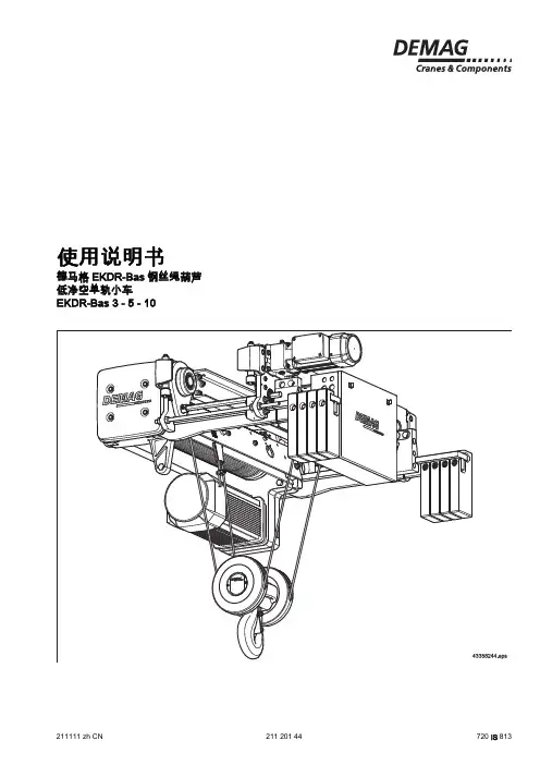
使用说明书德马格EKDR-Bas钢丝绳葫芦低净空单轨小车EKDR-Bas 3 - 5 - 10211111 zh CN211 201 44720 IS 813原始使用说明书在首次调试设备之前,请您首先完整填写以下表格。
由此,您的德马格DR-Bas 钢丝绳葫芦的资料不会和其他资料发生混淆,使您在有任何回询时可以得到明确的答复。
所有人使用地点型号出厂编号主起升电机编号工作电压控制电压频率电路图编号表 1本使用说明书讲述EKDR-Bas 起重机设备的全套供货内容。
关于各个组件的安装和故障排除请参阅这些构件的安装说明书。
全套供货内容包括以下文献。
名称/组件订购号分类行走机构EKDR-Bas 安装说明书211 200 44719 IS 813固定式葫芦FDR-Bas 3 - 5 - 10安装说明书211 211 44719 IS 813手电门DST-Bas 211 204 44719 IS 951控制器Bas 安装说明书211 205 44719 IS 813圆柱形转子电机MT-Bas 安装说明书211 196 44719 IS 951圆柱形转子电机MH-Bas 安装说明书211 212 44719 IS 951表 2除了本使用说明书之外,还可以提供关于设备构件或组件的印刷品。
以下列举出了可能的构件或组件。
相应的印刷品在需要的情况下随货提供,或者可以另行索取。
资料1)订购号分类备件清单德马格起升装置备件清单FDR-Bas 3 - 5 - 10217 066 44721 IS 813EU-/EK-/EZDR-Bas 3 - 5 - 10217 088 44721 IS 813技术数据/目录EKDR-Bas 技术数据203 736 44714 IS 813DST-Bas 技术数据203 744 44714 IS 951起重机和起升装置检测结果记录书请洽询720 IS 100表 31) 这些资料可以向德马格分支机构索取。
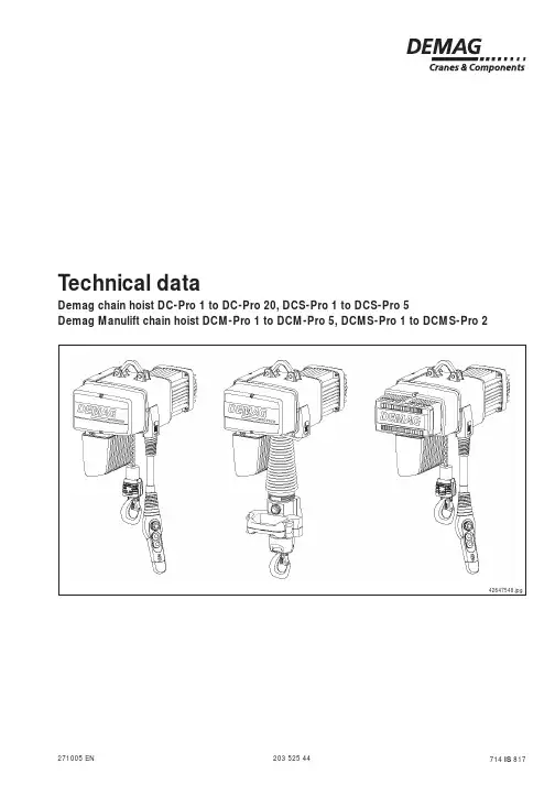
T echnical dataDemag chain hoist DC-Pro 1 to DC-Pro 20, DCS-Pro 1 to DCS-Pro 5Demag Manulift chain hoist DCM-Pro 1 to DCM-Pro 5, DCMS-Pro 1 to DCMS-Pro 2203 525 44271005 EN 714 IS 81742647548.jpg220352544.p 65/27100565789141011124312171816151342648344.jpg1Electrical equipment cover 2Brake3Slipping clutch 4Gearbox 5Chain guide6Suspension bracket 7Stator 8Rotor9Motor shaft 10End cap 11Fan cover 12Chain13Control cable lockDesign overview14Fan15Pulse wheel16Slipping clutch adjusting nut 17Hook assembly 18Load hook Single-fall designModel codeEU DC-Pro 10-1000H5V1380-415/5024/6100Flange width [mm] or I beam Travel speed [m/min]Frequency [Hz]Voltage range [V]Hoist speed Hook path [m]Load capacity [kg]Size DC - Demag chain hoist DCM - ManuliftDCS - Stepless chain hoist DCMS- Stepless ManuliftTrolley type CF - Click-fit U - Push-travel trolley E - Electric-travel trolley320352544.p 65/271005Selection criteria4 Very heavyHoist units which are usually subject to maximum or almost maximum loads.For the medium load spectrum and an average daily operating time of 2,66 hours,the table shows group 2 m+. For the load capacity of 250 kg, the diagram shows size DC-Pro 2-250.The load spectrum(in most cases estimated) can be evaluated in ac-cordance with the following definitions:1 LightHoist units which are usually subject to very small loads and in exceptional cases only to maximum loads.S W LOperating timeS W LOperating time3 HeavyHoist units which are usually subject to medium loads but frequently to maximum loads.S W LOperating time Operating time Very heavy dead loadSmall partial load Small dead load2 MediumHoist units which are usually subject to small loads but rather often to maximum loads.Heavy partial load Medium partial load Medium dead loadHeavy dead loadS W LThe size of the hoist is determined by the load spectrum, average operating time per working day, SWL and reeving.1.What are the operating conditions?2.What is the specified safe working load?3.To what height must the load be lifted?4.What is the required lifting speed?5.Do the loads need to be lifted and lowered with high precision?6.Is horizontal load travel necessary?7.How is the hoist to be controlled?2 x average hook path x no. of cycles/h x working time/day60 x hoist speed2 x 4 x 20 x 860 x 8Operating time/day === 2,66 hoursExample:Load capacity 250 kg Load spectrum “medium” from table Hoist speed 8 m/min 1/1 reeving Average hook path 4 m No. of cycles/h 20Working time/day 8 h The average operating time per working day is estimated or calculated as follows:1)FEM: 1Am for chain drive arrangement V2 speedd o h te m g n i v e e R eg n a R ez i S 1/11/2gk n i L W S420352544.p 65/271005Technical dataDC-Pro selection table (2 speeds)1)For motor key data, see page 8.2)2m+ corresponds to 1900 hours at full loadduration of service.3)1Am chain drive arrangementL W S ts i o h n i a h C de e p s t s i o H ez i s r o t o M )1ht a p k o o H f o p u o r G g n i v e e R th g i e w .x a M ]g k [ep y t ]z H 05t a n i m /m []z H 06t a n i m /m []m [sm s i n a h c e m ]g k [ME F h t a p k o o h r o f m5m8081V ...-1o r P -C D 0,2/0,84,2/6,92/8B 17K N Z 8d n a 5m41/122422V ...-2o r P -C D 4/618,4/2,910011V ...-1o r P -C D 0,2/0,84,2/6,92V ...-2o r P -C D 4/618,4/2,915211V ...-1o r P -C D 0,2/0,84,2/6,92V ...-2o r P -C D 4/618,4/2,910611V ...-2o r P -C D 0,2/0,84,2/6,9+m 2)22V ...-5o r P -C D 0,3/0,216,3/4,41m 482030021V ...-2o r P -C D 0,2/0,84,2/6,9+m 2)222422V ...-5o r P -C D 0,3/0,216,3/4,41m 482030521V ...-2o r P -C D 0,2/0,84,2/6,9+m 2)222422V ...-5o r P -C D 0,3/0,216,3/4,412/8A 08K N Z m 482035131V ...-5o r P -C D 5,1/0,68,1/2,7+m 2)22V ...-01o r P -C D 0,3/0,216,3/4,412/8A 001K N Z m 484250041V ...-5o r P -C D 5,1/0,68,1/2,72/8A 08K N Z +m 2)282032V ...-01o r P -C D 0,3/0,216,3/4,412/8A 001K N Z m 484250051V ...-5o r P -C D 5,1/0,68,1/2,72/8A 08K N Z +m 2)282032V ...-01o r P -C D 0,3/0,216,3/4,412/8A 001K N Z m 484250361V ...-01o r P -C D 5,1/0,68,1/2,7m32V ...-02o r P -C D 0,3/0,216,3/4,412/8B 001K N Z 65060081V ...-01o r P -C D 5,1/0,68,1/2,72/8A 001K N Z +m 2)284252V ...-02o r P -C D 0,3/0,216,3/4,412/8B 001K N Z 650600011V ...-01o r P -C D 5,1/0,68,1/2,72/8A 001K N Z 84252V ...-02o r P -C D 0,3/0,216,3/4,412/8B 001K N Z +m 2)3)2650605211V ...-02o r P -C D 5,1/0,68,1/2,7+m 2)21/25637006100021)For motor key data, see page 8.2)2m+ corresponds to 1900 hours at full loadduration of service.L W S t f i l u n a M de e p s t s i o H ez i s r o t o M )1ht a p k o o H f o p u o r G g n i v e e R th g i e w .x a M ]g k [ep y t ]z H 05t a n i m /m []z H 06t a n i m /m []m [sm s i n a h c e m ]g k [ME F h t a p k o o h r o f m8,2m3,4081V ...-1o r P -M C D 0,2/0,84,2/6,92/8B 17K N Z 3,4d n a 8,2m41/122422V ...-2o r P -M C D 4/618,4/2,915211V ...-1o r P -M C D 0,2/0,84,2/6,92V ...-2o r P -M C D 4/618,4/2,910521V ...-2o r P -M C D 0,2/0,84,2/6,9+m 2)22V ...-5o r P -M C D 0,3/0,216,3/4,412/8A 08K N Z m48203520352544.p 65/271005L W S ts i o h n i a h C d e e p s t s i o H ez i s r o t o M )1ht a p k o o H f o p u o r G g n i v e e R th g i e w .x a M ]g k [ep y t ]z H 06/05t a n i m /m []m [sm s i n a h c e m ]g k [v nn e n v xa m ME F h t a p k o o h r o f m5m808S V ...-1o r P -S C D 03034B 17K N Z 8d n a 5m41/15272001S V ...-1o r P -S C D 521S V ...-1o r P -S C D 061S V ...-2o r P -S C D 61+m 2)2002S V ...-2o r P -S C D 052S V ...-2o r P -S C D 513S V ...-5o r P -S C D 8514A 08K N Z 9213004S V ...-5o r P -S C D 005SV ...-5o r P -S C D DC-Pro selection table (stepless hoist speed)1)For motor key data, see page 8.2)2m+ corresponds to 1900 hours at full loadduration of service.1)For motor key data, see page 8.2)2m+ corresponds to 1900 hours at full loadduration of service.L W S t f i l u n a M d e e p s t s i o H e z i s r o t o M )1ht a p k o o H f o p u o r G g n i v e e R th g i e w .x a M ]g k [ep y t ]z H 06/05t a n i m /m []m [sm s i n a h c e m ]g k [v nn e n v xa m ME F h t a p k o o h r o f m8,2m 3,408S V ...-1o r P -S M C D 03034B 17K N Z 3,4d n a 8,2m 41/15272521S V ...-1o r P -S M C D 052SV ...-2o r P -S M C D 61+m 2)2620352544.p 65/271005Suspension42591547.jpgDC-Pro 10DC-Pro 20 up to 1000 kg Long suspension bracket,fitted as standard,used on trolley •U 11•articulated frame KBK II •load bar KBK II and III •crab frame II •KBK IIIalso possible:•RU/EU 11 / 22 / 36•U 22•KBK II (500 kg)•articulated frame KBK III •crab frame KBK I and IIIShort suspension bracket,included in cardboard box (conversion),used on trolley •U 11also possible:•RU/EU 11 and 22•U 22•KBK II (500 kg)DC-Pro 20> 1000 kgLong suspension bracket,fitted as standard,used on trolley •U 22•articulated frame KBK III •load bar KBK III •crab frame KBKalso possible:•RU/EU 22•RU/EU 36Short suspension bracket,included in cardboard box (conversion),used on trolley •U 22also possible:•RU/EU 2242591545.jpgDC-Pro 1-5Fitted as standard,suitable for:•KBK III•KBK articulated frame •KBK load bar •KBK crab frame •RU 6•RU 11, EU 11Included in cardboard box (conver-sion), suitable for:•KBK 100, KBK I, KBK II •CF 5•U 11•RU 3, from flange width 60 mm720352544.p 65/271005820352544.p 65/271005DC-Pro electrical key valuesHoist motor data (The tolerance of the voltage range must not exceed ± 10%.)ez i S ez i s r o t o M f o .o N se l o p M .x a m /.n i tn e r r u c g n i t r a t s d n a s t n e r r u c ~3,z H 05,V 514-083~3,z H 05,V 042-022P N F D C n N s t r a t S h/I N 083I N 514I x a m )1I A I /N 514s o c ϕNI N 022I N 042I x a m )1I A I /042N s o c ϕN]W k []%[]m p r []A []A []A []A []A []A [1o r P -C D 2/8B 17K N Z 850,00202704200,102,102,154,184,057,101,201,254,184,0281,004059202102,106,106,157,264,001,208,208,257,264,02o r P -C D 2/8B 17K N Z 801,00257604200,102,153,154,165,008,101,253,254,165,0273,004528202104,106,158,157,236,004,208,202,357,236,05o r P -C D 2/8A 08K N Z 841,00201704251,103,154,101,284,000,202,205,201,284,0265,004088202104,209,204,353,475,051,400,509,553,475,001o r P -C D 2/8A 001K N Z 872,00209604207,109,102,208,145,059,203,308,308,145,0201,104547202101,301,305,306,318,004,504,501,606,318,002o r P -C D 2/8B 001K N Z 845,00203704208,305,403,533,274,0-22,204539202108,508,603,857,406,0ez i S ez i s r o t o M f o .o N se l o p tn e r r u c g n i t r a t s d n a s t n e r r u c .x a m /.n i M ~3,z H 06,V 554-044~3,z H 06,V 084-064)2P N F D C n N h/s t r a t S I 44N 0I N 554I x a m )1I A I /N 554s o c ϕNI 64N 0I N 084I x a m )1I A I /N 084s o c ϕN]W k []%[]m p r []A []A []A []A []A []A [1o r P -C D 2/8B 17K N Z 860,00207804269,051,151,154,174,000,102,102,154,174,0222,004525302151,155,155,157,254,002,106,106,157,254,02o r P -C D 2/8B 17K N Z 811,00252804250,152,104,154,155,000,102,153,154,155,0244,004524302154,156,159,157,226,004,106,158,157,226,05o r P -C D 2/8A 08K N Z 871,00206804202,153,105,101,274,051,103,154,101,274,0276,004084302105,200,355,353,465,004,209,204,353,465,001o r P -C D 2/8A 001K N Z 823,00204804208,159,103,208,135,007,109,102,208,135,0203,104543302152,302,307,306,308,001,301,305,306,308,002o r P -C D 2/8B 001K N Z 856,00208804200,404,401,533,264,008,302,409,433,264,027,204535302101,607,601,857,495,008,504,607,757,495,0ez i S ez i s r o t o M f o .o N se l o p M .x a m /.n i tn e r r u c g n i t r a t s d n a s t n e r r u c ~3,z H 06,V 042-022)2P N F D C n N s t r a t S h/I 2N 02I 42N 0I x a m )1I A I /42N 0s o c ϕN]W k []%[]m p r []A []A []A [1o r P -C D 2/8B 17K N Z 860,00207804201,205,205,254,174,0222,004525302105,253,353,357,254,02o r P -C D 2/8B 17K N Z 811,00252804201,205,208,254,155,0244,004524302109,203,358,357,226,05o r P -C D 2/8A 08K N Z 871,00206804204,207,200,301,274,0276,004084302100,500,601,753,465,001o r P -C D 2/8A 001K N Z 823,00204804255,309,306,408,135,0203,104543302105,604,603,706,308,002o r P -C D 2/8B 001K N Z 856,002088042-27,2045353021ez i S ez i s r o t o M f o .o N s e l o p lM .x a m /.n i tn e r r u c g n i t r a t s d n a s t n e r r u c ~3,z H 05,V 525-005P N F D C n N s t r a t S h/I 05N 0I 25N 5I x a m )1I A I /25N 5s o c ϕN]W k []%[[m p r ]]A []A []A [1o r P -C D 2/8B 17K N Z 850,00202704257,059,059,054,184,0281,004529202109,052,152,157,264,02o r P -C D 2/8B 17K N Z 801,00257604208,059,001,154,165,0273,004528202101,152,154,157,236,05o r P -C D 2/8A 08K N Z 841,00201704259,050,151,101,284,0265,004088202109,103,207,253,475,001o r P -C D 2/8A 001K N Z 872,00209604253,105,157,108,145,0201,104547202104,205,208,206,318,002o r P -C D 2/8B 001K N Z 845,00203704252,306,302,433,274,022,204539202107,404,506,657,406,01)I max = maximum rated current for lowering operation.2)Voltages specified to CSA guideline.920352544.p 65/271005ez i S ez i s r o t o M f o .o N se l o p tn e r r u c g n i t r a t s d n a s t n e r r u c .x a m /.n i M ~3,z H 06,V 083~3,z H 06,V 575)2P N F D C n N h/s t r a t S I 083N I x a m )1I A I /83N 0s o c ϕNI 75N 5I x a m )1I A I /5N 57s o c ϕN]W k []%[]m p r []A []A []A []A [1o r P -C D 2/8B 17K N Z 860,00207804207,107,122,194,058,058,054,184,0222,004525302108,108,15,314,009,009,057,264,02o r P -C D 2/8B 17K N Z 811,00252804205,157,143,135,009,000,154,156,0244,004524302108,101,205,356,000,151,157,236,05o r P C D 2/8A 08K N Z 871,00206804205,157,151,264,019,000,101,264,0276,004084302104,301,400,595,009,152,253,456,001o r P -C D 2/8A 001K N Z 823,00204804204,209,200,235,053,155,101,285,0203,104543302108,303,409,328,004,207,208,378,002o r P -C D 2/8B 001K N Z 856,00208804204,504,607,234,000,305,333,205,027,204535302102,800,0104,536,006,406,557,407,0ez i s r o t o M V514-083V 042-022V525-005V554-044V084-064V 042-022V083V575z H 05z H 06]A []A []A []A []A []A []A []A [2/8B 17K N Z 666666662/8A 08K N Z 010161012/8A 001K N Z 6012/8B 001K N Z 6152016161520201Mains connection delay fuse linksez i s r o t o M V514-083V 042-022V525-005V554-044V084-064V 042-022V083V575z H 05z H 06]²m m []m []²m m []m []²m m []m []²m m []m []²m m []m []²m m []m []²m m []m []²m m []m [2/8B 17K N Z 5,10015,1985,10015,10015,10015,1675,10015,10012/8A 08K N Z 491362662/8A 001K N Z 272/8B 001K N Z 835,2121634745,2815,23487Supply cables 3) for 5% voltage drop ∆U and starting current I A1)I max = maximum rated current for loweringoperation.2)Voltages specified to CSA guideline.3)The lengths of the supply lines are calculated onthe basis of an earth-loop impedance of 200 m Ω.e z i s r o t o M 3,z H 06/05,V 084-083~]²m m []m [4B 17K N Z 5,10014A 08K N Z e z i s r o t o M 3,z H 06/05,V 084-083~]A [4B 17K N Z 64A 08K N Z Supply cables 3) for 5% voltage drop ∆U and starting current I AMains connection delay fuse linksDCS-Pro electrical key valuesThe tolerance of the voltage range must not exceed +5% or -10%.ez i S ez i s r o t o M se l o pf o .o N M .x a m /.n i n e r r u cg n i t r a t s d n a s t n e r r u c t3,z H 06/05,V 084-083~P N F D C n N I N 083M K M /N 084so c ϕN]W k []%[]m p r []A [1o r P -S C D 2o r P -S C D 4B 17K N Z 437,006084201,305,205,05o r P -S C D 4A 08K N Z 437,006045209,202,385,01020352544.p 65/271005Demag chain hoistDC-Pro 1 to DC-Pro 20 < 1000 kg, DCS-Pro 1 to DCS-Pro 51/1 reevingDC-Pro 1-20 chain hoist with short suspension bracketDC-Pro 1-20 chain hoist with long suspension bracket42064446.jpg42064545.jpge z i S r o t o M t e k c a r b n o i s n e p s u S t e k c a r b n o i s n e p s u S t r o h s g n o l tr o h s gn o l tr o h s gn o l ro t c e l l o c n i a h C e z i s x o b 5H 8H 5H 8H C1C b1b l )11l 2l 3l 3b 4b 6b d1d 2d 5b 3d 1h 2h 3h 5b 3d 1h 2h 3h 4h 5h 2/1o r P -C D 2/8B 17K N Z 5033435335633733048628312247320710638191294218227103362040361540038786361055o r P -C D 2/8A 08K N Z 05388359352453456408214186456257106591912915184271033920403615432387861020601o r P -C D 2/8A 001K N Z 0643943942856255169434818259823810672232421781813382250535684722538389183320602o r P -C D 2/8B 001K N Z 064394285285516516943481875933381067223242178181338225053568472253838918332061)The l dimension increases by 80 mm for DCS-Pro 1 to DCS-Pro 5.1)1)1120352544.p 65/271005Demag chain hoist DC-Pro 20 > 1000 kg 2/1 reeving42666045.jpgBottom block with cut-off switchsprings arranged outside, 2/1 reeving When a DK bottom block is used,dimension C is increased by 60 mm.42666144.jpgDC-Pro 20 chain hoist with long suspension bracketDC-Pro 20 chain hoists with 2/1 reeving and a hook path of 8 m are supplied a flexible chain collector bag (pay attention to dimensions).ez i S r o t o M t e k c a r b n o i s n e p s u S t e k c a r b n o i s n e p s u S t r o h s gn o l tr o h s gn o l tr o h s gn o l ro t c e l l o c n i a h C ez i s x o b 5H 8H 5H 8H 5H 8H 5H 8H 5H 8H C1C b1b 3b l1l 2l 3l 4b 6b d1d 2d 5b 3d 1h 2h 3h 5b 3d 1h 2h 3h 4h 5h 7450852852855165169439044814427220338754039410632421781812482250535684722538389183320602o r P -C D 2/8B 001K N Z1220352544.p 65/271005CF 5 trolleyFlange width b = 50 – 91 mm Max. SWL 550 kgMinimum curve radius 800 mmGirder connections by means of fish plates are not permitted in the area of the guide rollers.t m a x .=15Suitable forDemag chain hoist:DC-Pro 1-80 to 125,DC-Pro 2-80 to 250,DC-Pro 5-160 to 5001320352544.p 65/271005U 11 trolleyFlange width b = 58 – 200, 201 – 310 mm Max. SWL 1100 kgMinimum curve radius 1000 mm (Push travel)Minimum curve radius 2000 mm (Electric travel)Suitable forDemag chain hoist:DC-Pro 1-80 up to 125,DC-Pro 2-80 up to 250,DC-Pro 5-160 up to 500,DC-Pro 10-315 up to 1000,DC-Pro 20-630 up to 1000U 22 trolleyFlange width b = 82 - 200, 201 - 310 mm Max. SWL 2200 kgMinimum curve radius 2000 mm (Push travel)Minimum curve radius 3000 mm (Electric travel)Suitable forDemag chain hoist:DC-Pro 10-315 up to 1000,DC-Pro 20-630 up to 2000Pay attention to clearance dimensions for girder42652145.jpgn o i t a n g i s e D ss e n k c i h t e g n a l f .x a m n a l F ]m m [t 002-11U 2285013-11U 024*******.jpgU 22 trolleyfor girders to DIN 1025, part 1 + 5Pay attention to clearance dimensions for girderconnection by means of fish 42665944.jpg42652158.jpgn o i t a n g i s e D ss e n k c i h t e g n a l f .x a m d i w e g n a l F ]m m [t ]m m [002-22U 03002-28013-22U 013-1021420352544.p 65/271005E 11 / E 22 travel drive 220-480 V , 50 / 60 Hz, 3 ~Suitable for trolleys:U 11 / U 22KBK RF 125ez i S ez i s r o t o M tn e r r u c g n i t r a t s d n a s t n e r r u c .x a m /.n i M ~3,z H 06/05,V 084-022P N F D C n N h/s t r a t S I N 022I N 084I 022x a m I x a m84]W k []%[]m p r []A []A []A []A [11E M 65P M 520,0022680423,051,03,156,01,00405430211,155,06,23,122E L65P M 50,0020360425,042,061,185,02,00452520218,19,03,451,2Electrical dataSelection table1)possible by programming other parameters 2)1% max. incline climbing ability 3)stepless up to 24 m/minThe tolerance of the voltage range must not exceed +5% or -10%.See document 214 810 44 for further information.el b a e c a l p s i d .x a M .l c n i t h g i e w d a o l d a e d )2ev i r d l e v a r T de e p S s y e l l o r t e l b i s s o P th g i e w .x a M d a o l l l u f t a )3la i t r a p h t i w d a o l )1]g k [e p y T ]n i m /m []n i m /m []g k [001111E 6/420311U 4002222E 521F R ,22U 5Features42670744.jpg•All electrical connections are of plug-in design;•Inputs for limit switches and fast-to-slow limit switches are integrated into the control card;•Smooth starting via ramps;•E11/E22 is fitted to the relevant U11/U22 trolley;• E 22 can also be fitted to the new RF 125 friction wheel travel drive;•Control cable set (part no.720 070 45) and mains connection cable (part no. 720 072 45) are designed to provide the electrical connection between a chain hoist and the E 11 / E 22 cross-travel drive.E11/E22 units are shipped ready for operation.The following settings are also possible:•Travel speed, acceleration and brak-ing parameters can be programmed via DSE 8-C/DSE 10-C control pen-dant;•Load-sway damping can be activated for the cross travel motion;•Infinitely variable travel speed only in connection with DCS-Pro and DSE 10-CS.1520352544.p 65/271005E 11 / E 22 travel drive on U 11 / U 22 trolley42669454.jpgy e l l o r T 1A 1X 2X 3X 1T ]m m []m m []m m []m m []m m [11U 8505865111422U 068644711941620352544.p 65/271005Hook dimensions CDC-Pro, DCS-Pro chain hoist42598647.jpgManulift with short suspension bracket Manulift with long suspension bracketShort suspension bracket Long suspension bracket42598544.jpge z i S )1te k c a r b n o i s n e p s u s t r o h S te k c a r b n o i s n e p s u s g n o L C 1C C1C x o b r o t c e l l o c n i a h C x o b r o t c e l l o c n i a h C 5H 8H 5H 8H 1o r P -C D 5035335633433733042o r P -C D 5035335633433733045o r P -C D 05359352488353456401o r P -C D 06439428539462551602o r P -C D 7452852850855165161)Only DCS-Pro 1 to DCS-Pro 5 sizes are step-less.DCM-Pro, DCMS-Pro Manulift chain hoistez i S )1t e k c a r b n o i s n e p s u s t r o h S t e k c a r b n o i s n e p s u s g n o L C 1C C 1C h t a p k o o h r o f ro t c e l l o c n i a h C xo b h t a p k o o h r o f ro t c e l l o c n i a h C xo b m8,2m 3,45H m 8,2m 3,45H 1o r P -M C D 5365075333763473732o r P -M C D 5365075333763473735o r P -M C D 0860575938178875341)Only DCMS-Pro 1 to DCMS-Pro 2 sizes arestepless.1720352544.p 65/271005ez i S re d r i g o t e s r e v s n a r T re d r i g o t l e l l a r a P C 1C C1C x o b r o t c e l l o c n i a h C x o b r o t c e l l o c n i a h C 5H 8H 5H 8H 1o r P -C D 5835145440830140442o r P -C D 5835145440830140445o r P -C D 034774705524274205DC-Pro, DCS-Pro chain hoist with CF 5 trolleyTransverse to girder Parallel to girder42652544.jpgCurve radius 800 mmDC-Pro, DCS-Pro chain hoist with U 11 or U 22 trolleyTransverse to girder Parallel to girder42652644.jpg1)Dimensions C and C1 are reduced by 33 mm if ashort suspension bracket is used.2)< 1000 kg3)> 1000 kg, 2/1 reeving4)Only sizes DCS-Pro 1 to DCS-Pro 5 sizes arestepless.s u i d a r e v r u c m u m i n i M l e v a r t h s u P le v a r t c i r t c e l E ]m m []m m [11U 0001000222U 00020003ez i S )4ye l l o r T re d r i g o t e s r e v s n a r T re d r i g o t l e l l a r a P C 1C C 1C x o b r o t c e l l o c n i a h C x o b r o t c e l l o c n i a h C 5H 8H 5H 8H 1o r P -CD 11U 0630930245835145442o r P -C D 11U 0630930245835145445o r P -C D 11U 50425428403477470501o r P -C D )111U 54587576696520619622U 75509597618541630702o r P -C D )111U )254587576696520619622U )275509597618541630722U )34469769778663073081820352544.p 65/271005Order example: KBK 100 pillar-mounted slewing crane, outreach 2 mManulift also suitable for travel on KBK suspension monorails (see KBK systems brochure)Slewing rangeKBK 100: 270°KBK I : 270°41192745.jpg41192645.jpgKBK 100KBK IQuick release coupling for DSM-C, DSMS-C control unitQuick release coupling forDSM-C, DSMS-C control unit 1Load hook 5Pressure spring 2Load fixing 6Cylindrical pin 3Unlocking sleeve 7Swivel lock 4DSM-C, DSMS-C control unit,housing rear part41089844.jpgAccessories for DCM-Pro 1 to DCM-Pro 5, DCMS-Pro 1 to DCMS-Pro 2 - max. SWL 250 kg41113044.jpg41089744.jpgPart no. 835 665 44Part no. 835 584 44Load hook 250 kgSlewing load hook 250 kgBelt sling 125 kg 1)Gripper hook 125 kg Coupling pin 250 kg 41113144.jpgPart no. 565 696 44Part no. 565 695 44Part no. 835 580 4441113444.jpg1)Belt sling width 45 mm,max. dia. to be gripped 430 mmH o o k d i m e n s i o n C = 765 m mSlewing rangeKBK 100: 270°KBK I : 300°83558403.jpgPillar and wall-mounted slewing jib crane for DCM-Pro 1 and DCM-Pro 5,DCMS-Pro 1 and DCMS-Pro 2r o f e l b a t i u S t f i l u n a M 08-1o r P -M C D 08-1o r P -S M C D 521-1o r P -M C D 521-2o r P -M C D 052-2o r P -M C D 521-1o r P -S M C D 052-2o r P -S M C D sn o i s n e m i D mK B K 001K B K I A20,230,220,330,3-30,4B 00,320,3C 16,274,2D85,067,0te e h s a t a d l a c i n h c e t e e s n o i t a m r of n i r e h t r u f r o F )231S I 417(445653021920352544.p 65/2710051 set of pantograph-type tongs SZ 1-10-1Part no.565 601 44SZ 1/SZ 2SZ 1 - R/SZ 2 - RGripping capacityGripping capacity41192344.jpg 41192444.jpgExampleFor ordering pantograph-type tongs comprising articulation 1, size 10 clamping levers for 80 – 105 mm gripping range and size 1 clamping jaws, width b = 60 mm.Pantograph-type tongs for SWL up to 125 kgeg n a R g n i p p i r G y t i c a p a c b l n i m h x a m h e z i S .o n t r a P t h g i e W g k 1Z S 08-06060730915621-80-1Z S 441075655,3501-081-01-1Z S 44106565031-5011-31-1Z S 44207565551-0311-51-1Z S 442065657,3081-5511-81-1Z S 44307565502-0811-02-1Z S 4430656508-060020730915622-80-1Z S 444075653,4501-082-01-1Z S 44406565031-5012-31-1Z S 44507565551-0312-51-1Z S 445065655,4081-5512-81-1Z S 44607565502-0812-02-1Z S 44606565051-04Ø02107352202451-R -1Z S 448065650,42Z S 012-041060250915141-12-2Z S 442175657,4572-0121-72-2Z S 44216565043-5721-43-2Z S 44316565012-0410020250915142-12-2Z S 445175654,5572-0122-72-2Z S 44516565043-5722-43-2Z S 446165657,5003-001Ø06102552302603-R -2Z S 448165653,52020352544.p 65/271005Parallel grab system for SWL up to 125 kg40974244.jpg 40974944.jpg 40974344.jpg 40974844.jpg40974444.jpg40975044.jpgW1 rangePart no.: 840 850 44W3 rangePart no.: 840 849 44W2 rangePart no.: 840 848 44Technical data:Load capacity up to 125 kg Diameter 50 – 150 mm load support on both sides wide jaws 120 mmThis grab can be used for handling loads weighing up to 125 kg. Owing to the wide jaws, the load can be picked up safely even when picked up asymmetrically.Technical data:Load capacity up to 125 kg Diameter 60 – 130 mm load support on both sides narrow jaws 60 mmwith bore hole for splined shaftsThis grab can be used for handling loads weighing up to 125 kg. The load is picked up symmetrically. Long shafts and shafts with varying diameters can be handled when used together with extension set 1.Technical data:Load capacity up to 63 kg Diameter 50 – 150 mm maximum length 600 mm load support on one side narrow jaw 60 mmThe sliding jaw (left) is not fitted with a load support and is approx. only 17 mm thick. This makes this grab suitable for picking up shafts arranged close together.2120352544.p 65/27100541268144.jpg40975644.jpgSupporting jawsSupporting shaft Grub screwExtension set 1Part no.: 840 870 44The working range of the parallel grab system of the W3 range can be extended using the set of accessories illustrated below.By inserting the support shafts into the grab jaws, fitting the support jaws to the sup-port shafts and securing these items using grub screws, shafts with different diame-ters can be handled in a horizontal position.By sliding and turning the support jaws on the shaft, differences in diameter of up to30 mm can be compensated.ExampleContainer handling42301344.jpg42301544.jpg 41970644.jpg e p y t r e n i a t n o C ez i s r e n i a t n o C 004x 006003x 004r e n i a t n o c o r u E d i g i r )A M D V (T L K d i g i r e l b a t s u j d a sa h c u s s r e n i a t n o c s u o i r a V ot i B ,T L K z t U ,c e t o r u E r e f äh c S I S S ,F M A C R A ,B D P di g i r ts e u q e r n o s e p y t r e n i a t n o c r e h t O。
德马格注塑机使用手册目录1. 引言2. 注塑机概述3. 注塑机的工作原理4. 注塑机的操作步骤4.1 准备工作4.2 注塑机的开机操作4.3 模具安装4.4 材料投入4.5 开始注塑4.6 关机操作5. 注塑机的维护与保养6. 常见问题与解决办法7. 注意事项8. 结语第一章引言感谢您购买德马格注塑机,本手册将为您提供详细的使用指南,帮助您正确操作和维护注塑机,确保其稳定地运行和延长使用寿命。
第二章注塑机概述德马格注塑机采用先进的注塑技术,适用于各种注塑工艺,具有注塑速度快、注塑质量好、操作简便等特点。
注塑机由控制系统、液压系统、注射系统、冷却系统等组成。
第三章注塑机的工作原理德马格注塑机采用液压驱动系统,通过液压油泵将液压油送到液压缸,从而实现模具开合、注射等动作。
注射系统负责将熔化的塑料通过喷嘴注入模具中,通过冷却系统将注塑成型的产品冷却定型。
第四章注塑机的操作步骤4.1 准备工作在正式操作注塑机之前,必须对机器进行检查,确保各个部分都处于正常状态。
检查液压油的压力、润滑油的加油情况,清理模具、喷嘴和机器周围的杂物等。
4.2 注塑机的开机操作将电源线插入电源插口,打开电源开关,观察液晶屏上的显示状态。
根据提示,进行相应的设置,如温度设定、压力设定等。
4.3 模具安装将待生产的模具安装到注塑机上,并且确保模具的安装位置正确牢固,各个部分没有松动或者异常。
4.4 材料投入将塑料颗粒等原料投入注塑机的料斗中,注塑机会自动将原料进行熔化和储存,以便后续的注射过程。
4.5 开始注塑根据产品的工艺要求,在注塑机的控制面板上设置注塑参数,如温度、压力等。
确认无误后,按下注塑启动按钮,注塑过程开始。
4.6 关机操作当生产完成或需要停机维护时,首先要停止注塑过程,将所有参数恢复到初始状态,然后关闭注塑机的电源开关。
第五章注塑机的维护与保养定期保养注塑机是确保其正常运行和延长使用寿命的关键。
保养包括润滑油的更换、清洁注塑机表面、清理模具等。
德马格技术说明1.起重机钢结构技术规格1.1.主梁采用焊接箱型梁结构,起重机桥架按照德国工业标准DIN15018 和中国国家起重机设计标准GB3811-83 设计,并遵守安全操作规程国标GB6067-85。
1.2.用语起重机主梁及各个钢结构的钢板,均采用喷丸预处理,达到Sa2 标准,起重机主梁焊接采用全自动CO保护焊。
1.3.起重机端梁亦采用焊接箱型梁结构(进口)采用数控加工中心(NC)一次加工成型。
1.4.起重机主梁与端梁采用高强度螺栓连接,避免了主梁与端梁焊接变形。
主梁采用焊接箱型梁结构。
采用特殊的光学校准装置测量并对端面进行机加工,确保端梁联接精度以及端梁的平行度并以此确保起重机精度及运行平稳。
高强度联接螺栓确保安全可靠。
主梁焊接采用气体保护自动焊接,严格的质量控制体系确保焊接质量及整机质量。
2.起升机构技术规格(采用开放式卷扬机设计);2.1. 起升机构采用开放式卷扬机设计。
2.2. 吊钩均可手动旋转,带安全自锁。
2.3.卷扬机采用六级马达(6 pole motor)。
2.4. 卷筒采用双出绳设计,8/2 或4/2 绕绳法,在起升和下降过程中吊钩无偏移,完全垂直起升下降。
2.5. 钢丝绳最小破断强度大于等于1960 N/m㎡,不扭转设计。
2.6. 吊钩安全系数>5,材质为V class(i.e.34CrNiMo6)2.7. 钢丝绳采用德国 Casar Superplast。
2.8. 减速器采用油浴润滑。
减速器外壳为铸铁或球状石磨铸铁。
减速器Demag-HGL2.9. 起升机构采用变频减速及双靴式电动液压式制动系统。
2.10. 起升电动机配置过热保护功能。
上下限位采用DGS精确的齿轮转动式限位器,上升双段,下降双段。
当吊钩出在(或下)极限位置时可以可靠地切断电力回路使电动机停转;限位器的动作位置可随意调整,转换到卷筒圆周方向的重复精度小于等于正负2度;限位器上附有计数器,能记忆吊钩的升降行程(米数),由此可算出卷扬机的大致累计使用时间。
Demaghaitian Service第一章 显示器的操作原理 Egocontrol operating Philosophy1.1 操作终端 “NC4 控制器”Operating Terminal “Ergocontrol NC4”Fig. 1--1: Operating terminal “Ergocontrol (EC) NC4”液晶屏幕LCD Display功能组键 Function group key 数字键盘Numeric Keypad手动动作功能键 Manaulfunction button 状态选择键Mold selection button紧急停止按钮Emergency stop开关按钮ON/OFF button启动按钮Start button软驱Disk driver软件 Soft key光标移动键Cursor move key特殊功能键盘Special function key光标快速移动滑轮 Cursor move shuttle wheel 软键 Sorft keyDemaghaitian Service1. 1. 1 功能组键/Function Group KeysErgocontrol (EC) 显示屏中的页面均可通过屏幕下的相关热键(功能组键)翻到Ergocontrol (EC)screen pages are function relevant called up by pressing the hot keys (function group keys).按下这些按钮可直接翻到相关的主画面如:按 合模单元组键可直接翻到 “10模具设置”页By pressing these buttons is displayed the main page of the selected function group, e.g.EC screen page “10 MOULD” in function group “clamping unit”. 功能组键/Function group合模单元/CLAMPING UNIT功能组键/Function group注射单元/INJECTION UNIT功能组键/Function group 温度控制/TEMPERATURES 功能组键/Function group 程序选择/PROGRAMS 功能组键/Function group 加工控制/PROCESS CONTROFig. 1--2: Meaning of the function group keys其它的一些功能键均可通过按屏幕下的软键来选取Further function group relevant screen pages can be selected by pressing the appropriate softkeys (see also chapter 2. 3 and 2. 4. 1).按软件中的“返回”可退回至原有的画面中By pressing the softkey ”return” can be returned to the previously displayed screen page.软键图标:Softkey “return:1. 2 随机软盘的用法/Handling of the Machine Diskettes机器由于种种原因出现程序丢失时可通过重装随机软盘来恢复The machine programs have to be reloaded only when the program is crashed for anyreason.注意: 这些软盘“Boot CPU(机器控制程序)”,”Boot firmware(固化程序)”,”Boot picture(画面程序)”,”Boot Diagnostic —disk(清除程序)” 均能在将软盘插入软驱后重开电源时自动将程序载入机器 Note: The diskettes “Boot CPU” (machine control), “Boot Ergocontrol” (firmware andscreen layout) and “Diagnostic --DISK” (diagnosis of faults) are automatically loaded into machine control, when such a disk is in the disk drive unit while the machine is switched on.功能组键/Function group自动化/AUTOMATIZATION功能组键/Function group德马格机械手/HANDLING功能组键/Function group页面列表/PAGE LAYOUT 功能组键/Function group 服务页面/SERVICE 功能组键/Function group 警服页面/ALARMS ProcessDemaghaitian Service1.2. 1 安装CPU盘/Diskette “BOOT CPU”。
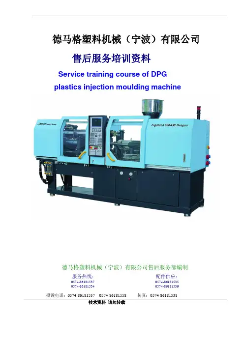
德马格塑料机械(宁波)有限公司售后服务培训资料Service training course of DPGplastics injection moulding machine德马格塑料机械(宁波)有限公司售后服务部编制服务热线:配件供应:****************************************************投诉电话:**************************传真:*************技术资料请勿转载第一章 显示器的操作原理Egocontrol operating Philosophy1.1 操作终端 “NC4 控制器”Operating Terminal “Ergocontrol NC4”Fig. 1--1: Operating terminal “Ergocontrol (EC) NC4”液晶屏幕LCD Display功能组键 Function group key 数字键盘Numeric Keypad手动动作功能键 Manaulfunction button状态选择键Mold selection button-紧急停止按钮Emergency stop开关按钮ON/OFF button启动按钮Start button软驱Disk driver软件 Soft key光标移动键Cursor move key特殊功能键盘Special function key光标快速移动滑轮 Cursor move shuttle wheel 软键 Soft key1. 1. 1 功能组键/Function Group KeysErgocontrol (EC) 显示屏中的页面均可通过屏幕下的相关热键(功能组键)翻到Ergocontrol (EC)screen pages are function relevant called up by pressing the hot keys (function group keys).按下这些按钮可直接翻到相关的主画面如:按 合模单元组键可直接翻到 “10模具设置”页By pressing these buttons is displayed the main page of the selected function group, e.g.EC screen page “10 MOULD” in function group “clamping unit”. 功能组键/Function group合模单元/CLAMPING UNIT功能组键/Function group注射单元/INJECTION UNIT功能组键/Function group 温度控制/TEMPERATURES 功能组键/Function group 程序选择/PROGRAMS 功能组键/Function group 加工控制/PROCESS CONTROFig. 1--2: Meaning of the function group keys其它的一些功能键均可通过按屏幕下的软键来选取Further function group relevant screen pages can be selected by pressing the appropriate softkeys (see also chapter 2. 3 and 2. 4. 1).按软件中的“返回”可退回至原有的画面中By pressing the softkey ”return” can be returned to the previously displayed screen page .软键图标:Softkey “return:1. 2 随机软盘的用法/Handling of the Machine Diskettes机器由于种种原因出现程序丢失时可通过重装随机软盘来恢复(详细的操作方法在后面的第七项有详细讲解)The machine programs have to be reloaded only when the program iscrashed for any reason.注意: 这些软盘“Boot CPU(机器控制程序)”,”Boot firmware(固化程序)”,”Boot picture(画面程序)”,”Boot Diagnostic —disk(清除程序)” 均能在将软盘插入软驱后重开电源时自动将程序载入机器 Note: The diskettes “Boot CPU” (machine control), “Boot Ergocontrol” (firmware andscreen layout) and “Diagnostic --DISK” (diagnosis of faul ts) are automatically loaded into machine control, when such a disk is in the disk drive unit while the machine is switched on.1.2. 1 安装CPU 盘/Diskette “BOOT CPU”。
德马格注塑机操作培训德马格注塑机操作培训是为工作人员提供注塑机操作技能和相关知识的培训课程。
在注塑生产过程中,操作人员的熟练程度直接影响到生产质量和效率。
因此,注塑机操作培训是非常必要的。
德马格注塑机是目前市场上较为常见的注塑机品牌,该品牌产品质量可靠、操作简单、生产效率高,深受用户的欢迎。
德马格注塑机操作培训主要包括以下内容:一、德马格注塑机的基本原理和结构在注塑机的操作培训中,了解德马格注塑机的基本原理和结构是先决条件。
培训内容主要包括:注塑机工作原理、注塑机的主要部件及其作用、注塑机的动力系统、注塑机运转过程中注意事项等。
二、注塑机的操作流程注塑机的操作流程包括:开机前的准备工作、调试及开机、生产过程中的操作、停机后的清洗和维护等。
在培训中,除了讲解操作流程,还必须做好实践操作,以加深学员对注塑机操作的理解和熟练程度。
三、注塑机生产过程中的常见故障和解决方法在注塑机生产过程中,常会遇到机器出现一些故障,如温度控制不准确、料斗堵塞、机器运转异常等。
这些故障需要及时解决,才能保证生产效率。
因此,在注塑机操作培训中,必须加强对机器常见故障和解决方法的讲解。
四、注塑机使用过程中的安全注意事项注塑机虽然生产效率高,但如果不注意安全,可能会产生一些事故,对工作人员的健康和生命构成威胁。
因此,在注塑机操作培训中,必须加强安全教育,讲解注塑机操作时的注意事项,强化安全意识,确保工作人员的安全。
德马格注塑机操作培训除了以上内容之外,还应考虑到学员的实际情况和需求,根据学员的职业特点和经验水平,进行针对性的培训,以达到培训效果的最大化。
在注塑机操作培训中,要注重实践操作,提高学员对注塑机操作流程和操作技能的掌握程度,以达到注塑机在生产中的高效率使用。
同时,在注塑机的操作培训过程中,要强化学员的安全意识,以保障操作人员的生命安全。
综上所述,德马格注塑机操作培训是非常必要的,不仅能提高操作人员对注塑机的操作水平和技术素质,同时也能提高注塑机的生产效率和质量。
德马格技术说明德马格技术说明1.起重机钢结构技术规格主梁采用焊接箱型梁结构,起重机桥架按照德国工业标准DIN15018 和中国国家起重机设计标准GB3811-83 设计,并遵守安全操作规程国标GB6067-85。
用语起重机主梁及各个钢结构的钢板,均采用喷丸预处理,达到Sa2 标准,起重机主梁焊接采用全自动CO保护焊。
起重机端梁亦采用焊接箱型梁结构(进口)采用数控加工中心(NC)一次加工成型。
起重机主梁与端梁采用高强度螺栓连接,避免了主梁与端梁焊接变形。
主梁采用焊接箱型梁结构。
采用特殊的光学校准装置测量并对端面进行机加工,确保端梁联接精度以及端梁的平行度并以此确保起重机精度及运行平稳。
高强度联接螺栓确保安全可靠。
主梁焊接采用气体保护自动焊接,严格的质量控制体系确保焊接质量及整机质量。
2.起升机构技术规格(采用开放式卷扬机设计);2.1. 起升机构采用开放式卷扬机设计。
2.2. 吊钩均可手动旋转,带安全自锁。
2.3.卷扬机采用六级马达(6 pole motor)。
2.4. 卷筒采用双出绳设计,8/2 或4/2 绕绳法,在起升和下降过程中吊钩无偏移,完全垂直起升下降。
2.5. 钢丝绳最小破断强度大于等于1960 N/m㎡,不扭转设计。
2.6. 吊钩安全系数>5,材质为V class(i.e.34CrNiMo6)2.7. 钢丝绳采用德国 Casar Superplast。
2.8. 减速器采用油浴润滑。
减速器外壳为铸铁或球状石磨铸铁。
减速器Demag-HGL2.9. 起升机构采用变频减速及双靴式电动液压式制动系统。
2.10. 起升电动机配置过热保护功能。
上下限位采用DGS精确的齿轮转动式限位器,上升双段,下降双段。
当吊钩出在(或下)极限位置时可以可靠地切断电力回路使电动机停转;限位器的动作位置可随意调整,转换到卷筒圆周方向的重复精度小于等于正负2度;限位器上附有计数器,能记忆吊钩的升降行程(米数),由此可算出卷扬机的大致累计使用时间。
德马格技术说明
1.起重机钢结构技术规格
1.1.主梁采用焊接箱型梁结构,起重机桥架按照德国工业标准DIN15018 和中
国国家起重机设计标准GB3811-83 设计,并遵守安全操作规程国标GB6067-85。
1.2.用语起重机主梁及各个钢结构的钢板,均采用喷丸预处理,达到Sa2 标
准,起重机主梁焊接采用全自动CO保护焊。
1.3.起重机端梁亦采用焊接箱型梁结构(进口)采用数控加工中心(NC)一
次加工成型。
1.4.起重机主梁与端梁采用高强度螺栓连接,避免了主梁与端梁焊接变形。
主
梁采用焊接箱型梁结构。
采用特殊的光学校准装置测量并对端面进行机加工,确保端梁联接精度以及端梁的平行度并以此确保起重机精度及运行平稳。
高强度联接螺栓确保安全可靠。
主梁焊接采用气体保护自动焊接,严格的质量控制体系确保焊接质量及整机质量。
2.起升机构技术规格(采用开放式卷扬机设计);
2.1. 起升机构采用开放式卷扬机设计。
2.2. 吊钩均可手动旋转,带安全自锁。
2.3.卷扬机采用六级马达(6 pole motor)。
2.4. 卷筒采用双出绳设计,8/2 或4/2 绕绳法,在起升和下降过程中吊钩无
偏移,完全垂直起升下降。
2.5. 钢丝绳最小破断强度大于等于1960 N/m㎡,不扭转设计。
2.6. 吊钩安全系数>5,材质为V class(i.e.34CrNiMo6)
2.7. 钢丝绳采用德国 Casar Superplast。
2.8. 减速器采用油浴润滑。
减速器外壳为铸铁或球状石磨铸铁。
减速器
Demag-HGL
2.9. 起升机构采用变频减速及双靴式电动液压式制动系统。
2.10. 起升电动机配置过热保护功能。
上下限位采用DGS精确的齿轮转动式限位器,上升双段,下降双段。
当吊钩出在(或下)极限位置时可以可靠地切断电力回路使电动机停转;
限位器的动作位置可随意调整,转换到卷筒圆周方向的重复精度小于等
于正负2度;限位器上附有计数器,能记忆吊钩的升降行程(米数),
由此可算出卷扬机的大致累计使用时间。
另配置机械式上闲位开关,以
实现双重保护。
2.11. 过载保护器:
采用FGB/FAW型电子式过载保护器,保证起升总吊重不会超过桥架额定起重量;当钢丝绳拉力大于110%额定值时,该过载保护装置会自动切
断起升回路,该装置经200万次工作循环后,最大动作误差小于等于正
负2.5%
3.起重机大车行走机构和小车行走机构技术规格
3.1.大车运行机构采用“电动机+减速箱+走轮”三合一结构。
3.2.小车运行机构采用“电动机+减速箱+走轮”三合一结构。
3.3.所有轴承为自润滑的含油式,布置方式可有效吸收水平力。
3.4.减速器所有齿轮须经表面硬化处理,为了降低噪声,所有齿轮必须经过
磨削或者剃齿,齿轮箱在使用寿命内不须换油。
3.5.制动器可靠性在100万次以上。
3.6.大车限位开关:大车限位开关采用十字行程限位开关,在起重机缓冲器与
轨道末端挡块碰撞之前将大车运行速度由快速转为慢速,或由慢速转为零。
3.7.小车限位开关:小车限位开关采用十字行程限位开关,在小车缓冲器与小
车轨道末端挡块碰撞之前将小车运行速度由快速转为慢速,或由慢速转为零。
3.8.整个行走机构的防护等级为IP54,驱动电机的绝缘等级为F级。
3.9.大车行走车轮采用球墨铸铁车轮,球墨铸铁材料消除振动性能比普通铸钢
车轮好得多,并且带有自润滑功能,可大大减小车轮与轨道的摩擦,减小噪声,延长车轮使用寿命。
球墨铸铁轮子内部安装了一个含30%高分子玻
璃纤维聚酯化合物的轮,也大大提高了车轮的减振性能。
3.10.整套机构按照免维护要求设计。
顺颂商祺!
(注:文档可能无法思考全面,请浏览后下载,供参考。
可复制、编制,期待你的好评与关注)。